





Introduction
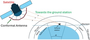
The end goal of this work is to retrieve data from a satellite when it appears near the horizon. To accomplish this, an antenna is required that gives a sufficient effective area, maintains a low sidelobe level (SLL), and produces a high-gain beamformed pattern to ensure efficient data retrieval. When a satellite is near the horizon, its distance from the ground station is maximum. In such cases, the antenna located on the lower side of a conventional planar array may not give a sufficient effective area for efficient communication. This drawback led to the development of a conformal array design, as shown in Figure 1. We provide below a brief review of such arrays.
Basic communication arrangement between the ground station and the satellite.

In reference [Reference Schippers, Verpoorte, Jorna, Hulzinga, Meijerink, Roeloffzen, Heideman, Leinse and Wintels1], the authors demonstrate a broadband Ku-band antenna design together with a beam synthesis method for conformal array antennas. The Ku-band antenna is implemented using a stacked patch structure with dual linear polarization, whereas the beam synthesis is obtained using a truncated singular value decomposition method. In [Reference Yang, Li, Zhou and Qi2], the authors presented a wide-beam microstrip antenna enclosed by metallic boundaries, explicitly developed to strengthen the wide-angle operational capability of phased array antennas. The antenna shows a scanning range between  $-70$ and $70$ deg. from 3.7 to 4.3 GHz, while maintaining a gain variation within 2.7 dB. Additionally, the maximum SLL fluctuation is kept below 5.8 dB. The authors presented an individual-element beam-scanning antenna utilizing a coupled-mode patch design, capable of directing the beam profile in terms of frequency by employing a single electronically tunable component [Reference Tian, Jiang and Itoh3]. In reference [Reference Ding, Cheng, Shao, Li, Wang and Anagnostou4], the authors utilized a pattern-reconfigurable technique and a magnetic current source to design the radiating source of a wide-angle scanning array. The proposed array is capable of scanning the entire upper ground elevation plane, from $-90$ to $90$ deg., at an operating frequency of 5.8 GHz, while maintaining a beamwidth of 3 dB. In [Reference Beenamole, Kutiyal, Revankar and Pandharipande5], the authors designed a printed meander-line microstrip antenna working in the S-band. The antenna exhibits a wide impedance bandwidth of 400 MHz and shows an E-plane beamwidth of $130$ deg. Given these characteristics, the proposed antenna is well-suited for active phased array radar systems, particularly those requiring a scan angle of $\pm60$ deg. Most of the studies presented above are designed using planar antenna structures, generally employing active device integration to achieve beam steering. Although these methods show good scanning properties, they often show significant variation in gain and, above all, require a large number of active elements.
To address this, sparse antenna arrays are proposed, where a limited set of antennas are arranged over a large aperture instead of occupying all possible element locations. When the array covers a curved structure, grating lobes traditionally appearing in planar arrays may be strongly reduced. This approach lowers mass and complexity, rendering them well-suited to meet severe space constraints. Moreover, the beamforming capacity of sparse antenna arrays enables the system to adapt and merge signals from different array elements, effectively concentrating the radiated energy in the desired direction. This process improves both the antenna’s gain and effective area, thereby enhancing link quality and ensuring robust and dependable communication, even when the satellite is positioned low on the horizon. With respect to gain enhancement in sparse antenna arrays, the partially reflecting surface (PRS)-based antennas have drawn notable interest owing to their compact design and the easy fabrication they offer for achieving substantial gain improvement [Reference Leger and Jecko6].
In the literature, a PRS can occur in various forms, which are commonly divided into three classes: (1) single-layer dielectric covers [Reference Jackson and Alexopoulos7, Reference Jackson and Oliner8], (2) dielectric multilayers [Reference Jackson, Oliner and Ip9], and (3) homogenized metasurfaces [Reference Holloway, Kuester, Gordon, O’Hara, Booth and Smith10]. Each of them offers different structural behaviors and design flexibility, ensuring that the PRS design can be adjusted for the specified relative bandwidth and operational requirements.
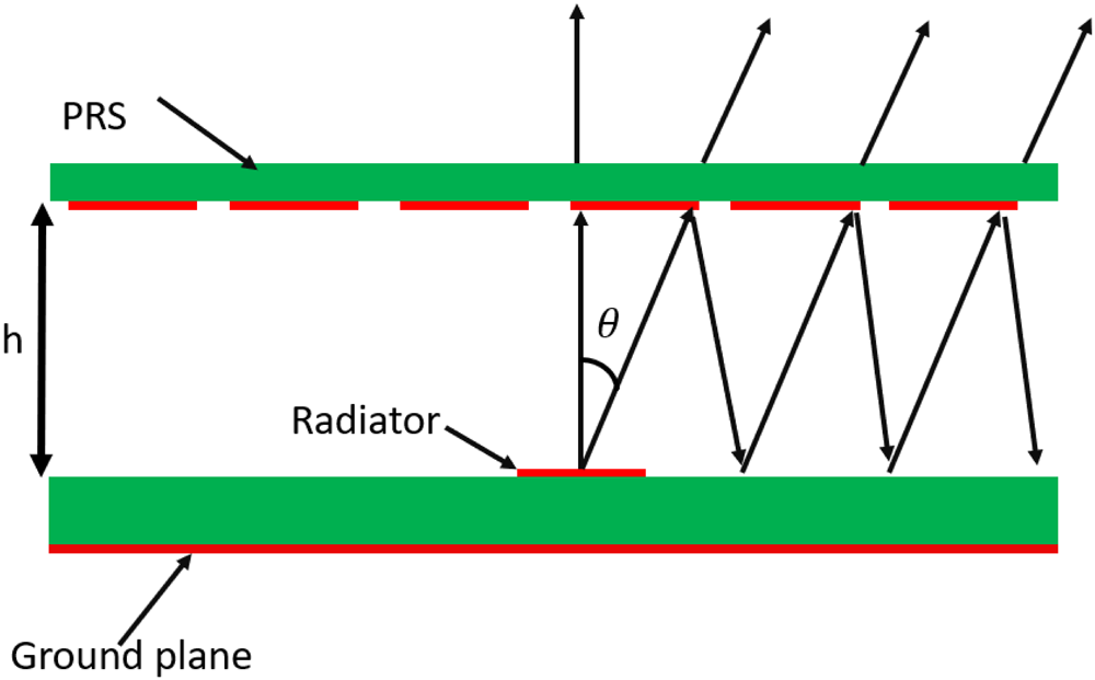
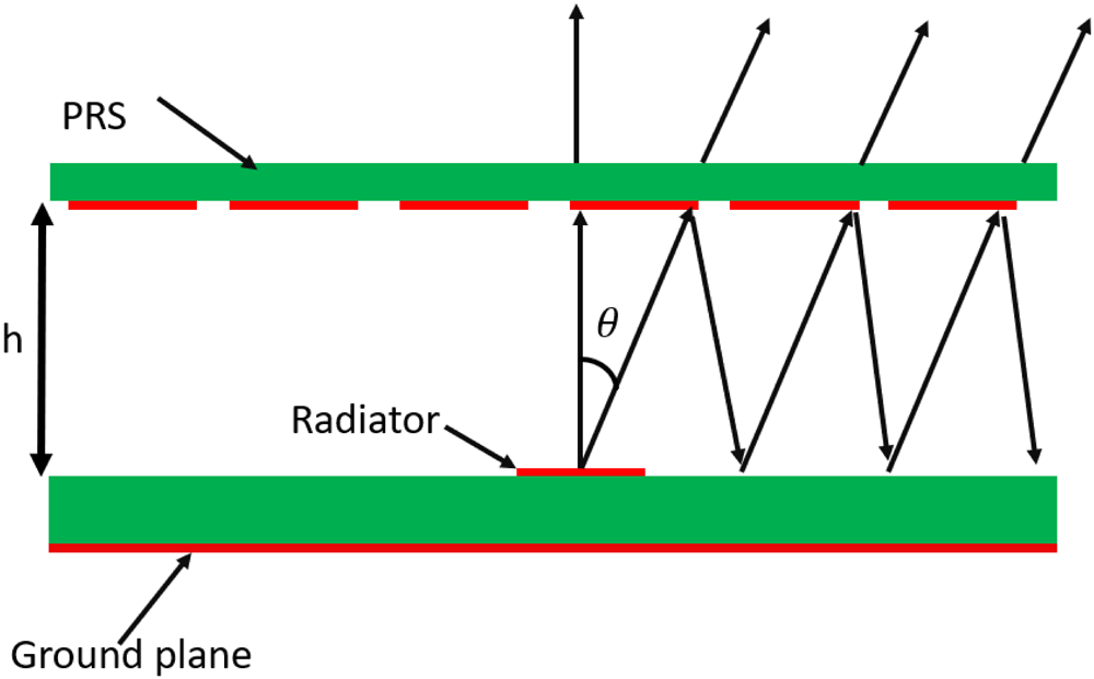
The formation of a PRS-based antenna is relatively simple, as it can work in various forms of partially reflecting sheets. However, the choice of sheet type depends primarily on the operating relative bandwidth and on the array configuration. The source element in a PRS-based antenna is generally a microstrip patch antenna, excited within a Fabry–Perot cavity (FPC) by the antenna’s ground plane and a PRS kept at approximately  $\lambda/2$ [Reference von Trentini11] above; a schematic model is shown in Figure 2 [Reference Feresidis, Goussetis, Wang and Vardaxoglou12]. The electromagnetic wave emitted by the radiating source undergoes several reflections within the cavity, with a portion of its energy passing through the PRS during each reflection, gradually adding to the antenna’s outward radiation. The spacing between the ground and the PRS is carefully optimized so that the electromagnetic waves passing through the PRS are superimposed constructively towards broadside at the operating frequency, thereby maximizing the antenna’s gain.
Schematic model of the FPC antenna.
In [Reference Zhao, Jackson, Williams and Oliner13], the authors presented a simple CAD-based formulation of a dielectric leaky-wave antenna, which helps estimate its radiation properties. The authors utilized a direct circularly polarized (CP) source antenna formed using four linearly polarized (LP) stripline slot arrays. This structure acts as the source for the Fabry–Perot (FP) antenna, ensuring the development of circular polarization [Reference Liu and Lu14]. In this reference [Reference Qin, Gao, Wei, Luo, Mao, Gu, Xu and Li15], the authors deployed a dual-layer PRS positioned above the main radiating element. This multilayer configuration amplified the constructive interference within the FPC, attaining a 14.7 dBi measured gain across a 28.3  $\%$ operational range. The authors presented a CP FP antenna that combines a dual-sided PRS with an anisotropic high-impedance surface. CP is attained by exciting the structure with an LP source oriented at $45$ deg., which creates the orthogonal field components. The antenna realized a gain of 21.1 dBi at 15 GHz through this design [Reference Orr, Goussetis and Fusco16]. In reference [Reference Ren, Jiang, Zhang and Gong17], the authors proposed a linear-to-circular polarization converter to get a high-gain, low radar cross-section CP FP antenna. The design uses an LP antenna, aligned at $45^{\circ}$ in the horizontal plane, as the primary source. At the same time, an asymmetric metasurface acts as a polarization converter to create circular polarization. The authors proposed an FPC antenna target for enhancing high-data-rate CubeSat communication. The antenna is intended to offer left-hand circular polarization, obtaining a gain of 15.1 dBi at an operating frequency of 8.7 GHz and with a gain variation of less than 0.5 dBi throughout the band [Reference De, Abegaonkar and Basu18]. In reference [Reference Konstantinidis, Feresidis and Hall19], the authors designed a multilayer broadband FP-type antenna including a three-layer PRS. The proposed antenna provides a gain of 20 dBi and offers a 15 $\%$ bandwidth at an operational frequency of 14.5 GHz. The studies above highlight CP FP antennas, using different polarization methods and multilayer configurations to achieve high gain and better radiation characteristics for practical uses such as satellite communication.
A preliminary edition of the paper was reported at the 19th Conference of Antennas and Propagation (EuCAP 2025) and published in its proceedings [Reference Kumar and Craeye20]. The subsequent sections of the paper are arranged as follows. The design of the CP unit antenna utilizing a PRS is described in the second section. The third section covers the conceptual framework and implementation of the beamforming method. The fourth section gives the results and an in-depth discussion, whereas the fifth section presents the conclusion and the main remarks.
Design of the unit antenna and results
In this work, a circular polarized antenna is targeted, which helps to maximize the polarization efficiency as the satellite moves. It can also reduce the loss caused by misalignment between the receiver and transmitter. Circular polarization (CP) is measured by the axial ratio (AR), which is defined as the ratio between the lengths of the major and minor axes of the polarization ellipse. There are many ways to get circular polarization with a PRS, such as selecting the position of the feed diagonally on the rectangular microstrip patches, introducing diagonal slots on the square patch, and trimming the ends of the two corners of the square [Reference Balanis21]. Here, the four LP antennas are in an array with a sequential phase difference of  $90$ deg. [Reference Huang22]. Ideally, an AR less than 1 dB is difficult to achieve, such that typically, a 3 dB AR is often specified.
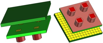
Figure 3 depicts the perspective view of the present PRS-based antenna designed for performance at 23 GHz (K band). The system consists of an array of LP patch elements positioned at a height  $h$ below the PRS, acting as the radiating source. The antenna has been modeled and optimized using the CST Microwave Studio’s frequency-domain solver [23]. The PRS structure consists of a dielectric substrate attached to a metallic patch. Both the PRS substrate and the metallic substrate are made of the same material, Rogers RT5880, for its low dielectric constant and low dielectric loss. The dimensions of the PRS and metallic patch are 22.3 mm $\times$ 22.3 mm $\times$ 1.2 mm and 1.85 mm $\times$ 1.85 mm $\times$ 0.035 mm, respectively. The source patch, the underlying substrate, and the ground plane possess dimensions of $2~\text{mm} \times 3~\text{mm} \times 0.035~\text{mm}$, $20~\text{mm} \times 20~\text{mm} \times 1.35~\text{mm}$, and $20~\text{mm} \times 20~\text{mm} \times 0.035~\text{mm}$, respectively, with excitation provided through a coaxial feed.
Perspective view of unit antenna.
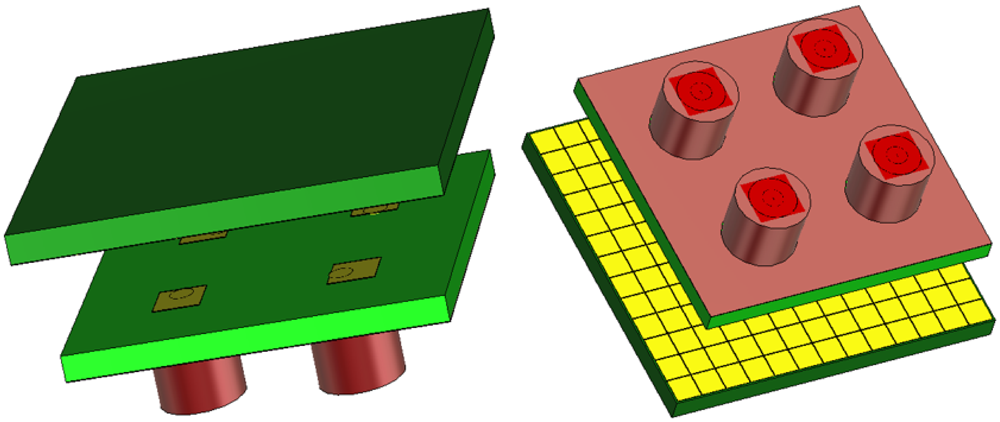
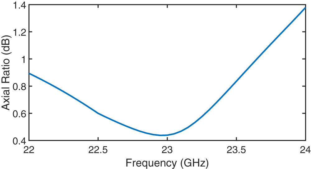
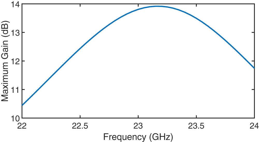
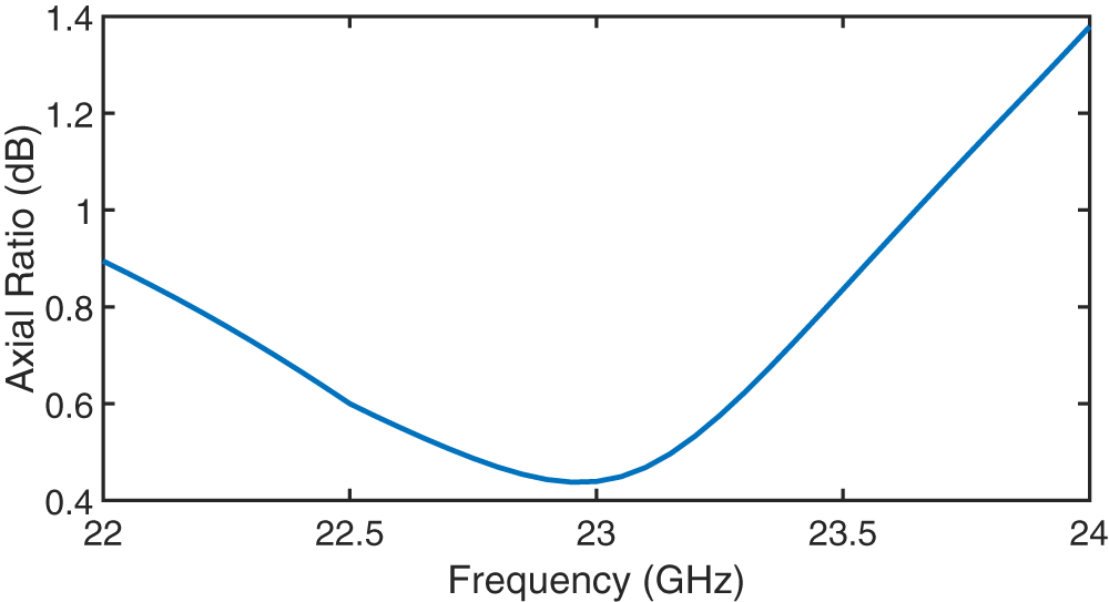
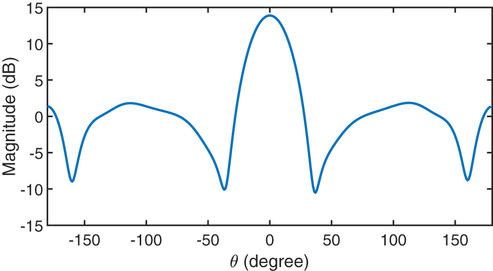
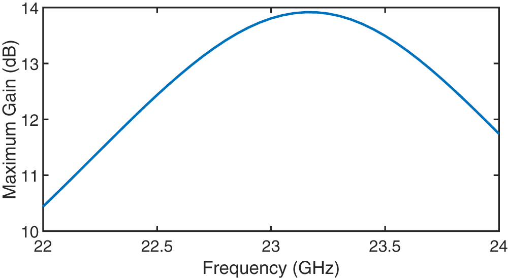
Figure 4 depicts the AR curve of the unit antenna across the operational frequency range. The results indicate that the AR remains less than 3 dB, satisfying the circular polarisation condition. Figure 5 portrays the simulated radiation pattern of the unit antenna at an elevation cut for 23 GHz. Figure 6 demonstrates the simulated gain of the unit antenna with respect to frequency. The curve depicts that the antenna obtains its maximum gain at 23 GHz, shows maximum performance at the design frequency, and indicates the gain variation over the operational bandwidth.
AR vs frequency of unit antenna.
Radiation pattern vs elevation angle ( $\theta$ plane) of unit antenna.

Maximum gain vs frequency of unit antenna.
Theory and implementation of beamforming
Each feed of the array is in a sparse configuration, since there is only one per facet. The sparse configuration helps to reduce the antenna elements, lowering cost, weight, complexity, and minimizing the mutual coupling. Also, if the facets are arranged on a curved structure, this leads to attenuation of grating lobes by thinning the array. However, it introduced the issues of a broader main beam, elevated sidelobes, and limited sidelobe suppression. In order to address these issues, the embedded element pattern (EEP) is first analyzed.
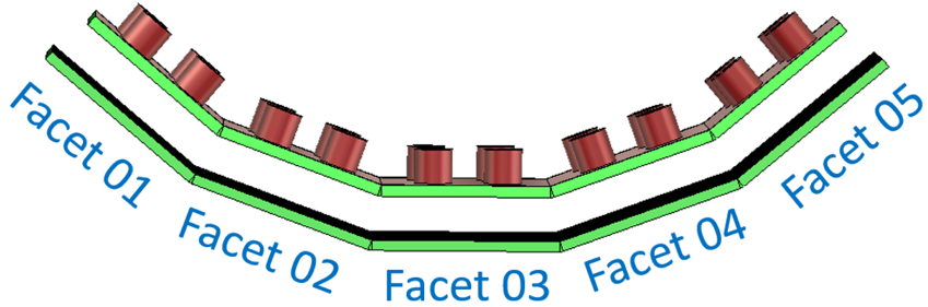
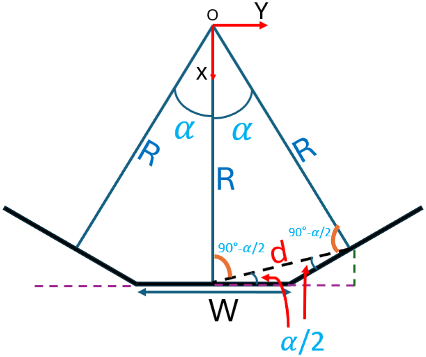
In the present work, each facet of the array is arranged in a conformal configuration as shown in Figure 7, with an inclination angle between facets represented by  $\alpha$. The center of each facet is kept at a radial distance $R$ from the array’s central reference point, as shown in Figure 8. Each facet is modeled individually, will be fabricated separately, and subsequently assembled. Altogether, the facets are designed to provide the required beam coverage, which helps to direct or receive signals over the complete target angular range. The angular field distribution is determined by the orientation of the neighboring facets. This section describes the beamforming method applied to the faceted antenna array, utilizing the radiation pattern data obtained in the previous section. In this analysis, the mutual coupling effects between facets are included, and the EEP [Reference Warnick, Davidson and Buck24] theory is applied to model the array pattern. The EEP accounts for how each facet’s radiation is affected by the presence of neighboring elements. This analysis calculates specific excitation weights for every facet, allowing good beam steering and sidelobe control across the required coverage area.
Full array of the structure.
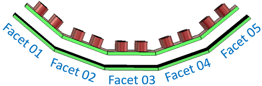
2D view of antenna array.

We consider a collection of  $N$ antennas, where $\vec{F_i}$ denotes the copolar - radiation pattern of the $i_{th}$ element, which relates to a PRS-based antenna, while including the influence of adjacent facets.
 \begin{equation}
\vec{F_i} = \left|{F_i}{(\theta)}\right|e^{{j\varphi_i}({\theta})} \hat{e}_p
\end{equation}
\begin{equation}
\vec{F_i} = \left|{F_i}{(\theta)}\right|e^{{j\varphi_i}({\theta})} \hat{e}_p
\end{equation}where  $\hat{e}_p$ denotes a complex unit vector standing for the desired circular polarization. The reference point for the phase is located at the antenna feed point.
This  $\vec{F_i}$ is obtained with the help of CST Microwave Studio, as discussed in the earlier section. The array arrangement can be closed, meaning that the angle $\alpha$ between neighboring facets is an integer fraction of 2 $\pi$, or it includes a sufficiently large number of facets such that the EEP of each facet can reasonably be assumed to be identical. This assumption simplifies the beamforming calculations, as it allows the same radiation pattern to be applied across all facets of the array.
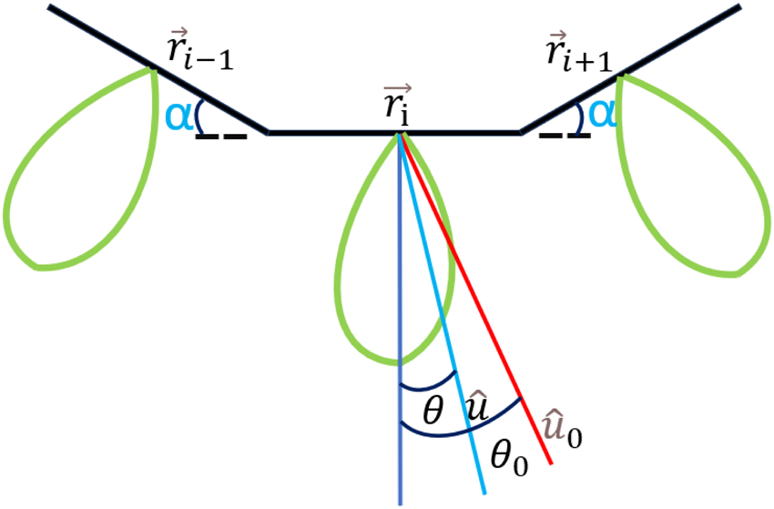
The radiation pattern with phase reference at the center of the multifaceted structure by the  $i_{th}$ facet of the array in direction $\theta$, as illustrated in Figure 9, is denoted by
 \begin{equation}
\vec{F_i}{(\theta)} = \left|{F_i}{(\theta)}\right|e^{{j\varphi_i}{({\theta})}}e^{-jk\hat{u}\cdot\vec{r}_{i}} \hat{e}_p
\end{equation}
\begin{equation}
\vec{F_i}{(\theta)} = \left|{F_i}{(\theta)}\right|e^{{j\varphi_i}{({\theta})}}e^{-jk\hat{u}\cdot\vec{r}_{i}} \hat{e}_p
\end{equation}Unit vector direction of antenna array.
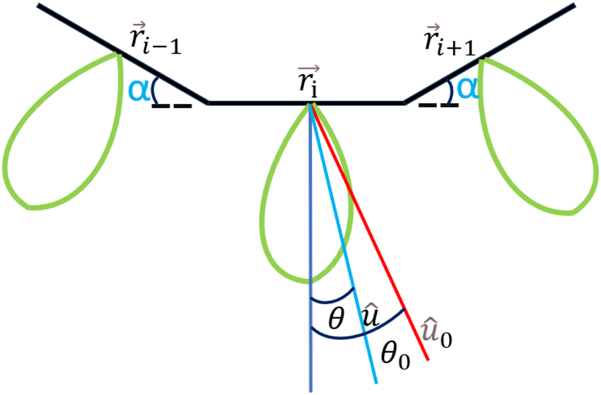
where  $\hat{u}$ is a unit vector pointing in the observation direction, while $\vec{r}_{i}$ depicts the reference point for phase measurement on the $i_{th}$ antenna. In this derivation, $\vec{r}_{i}$ is taken as the vector from the center of the structure to the intersection point where the connector meets the ground plane. The parameter $k$ is the free-space wavenumber, formulated as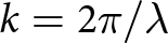 $k = 2\pi/\lambda$, where $\lambda$ is the free-space wavelength.
Due to the circular symmetry of the array structure,
 \begin{equation}
\vec{F_i}{(\theta)} = \vec{F_0}{(\theta-i\alpha)}
\end{equation}
\begin{equation}
\vec{F_i}{(\theta)} = \vec{F_0}{(\theta-i\alpha)}
\end{equation}where  $\vec{F_0}$ represents the EEP related to the facet that is always oriented toward nadir. Section IV will show how the approximation of $\vec{F_0}$ is obtained from analysis of smaller structures. From there, the field pattern observed at an angular distance from the $i_{th}$ facet antenna using Equation ( $3$) can be written as
 \begin{equation}
\vec{F_i}{(\theta)} = \left|{F_0}{(\theta-i\alpha)}\right|e^{{j\varphi}{{(\theta-i\alpha)}}}e^{-jk\hat{u}\cdot\vec{r}_{i}} \hat{e}_p
\end{equation}
\begin{equation}
\vec{F_i}{(\theta)} = \left|{F_0}{(\theta-i\alpha)}\right|e^{{j\varphi}{{(\theta-i\alpha)}}}e^{-jk\hat{u}\cdot\vec{r}_{i}} \hat{e}_p
\end{equation}where the final components for the change in propagation distances between the radiating element and the observation point are considered, considering the phase variation that occurs due to these path-length differences.
The array pattern after beamforming is represented by
 \begin{equation}
\vec{P}{(\theta)} = \sum_{i=1}^{N}\left|{F_0}{(\theta-i\alpha)}\right|e^{j\varphi(\theta-i\alpha)}e^{-jk\hat{u}\cdot\vec{r}_{i}}w_i \hat{e}_p
\end{equation}
\begin{equation}
\vec{P}{(\theta)} = \sum_{i=1}^{N}\left|{F_0}{(\theta-i\alpha)}\right|e^{j\varphi(\theta-i\alpha)}e^{-jk\hat{u}\cdot\vec{r}_{i}}w_i \hat{e}_p
\end{equation}where 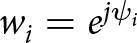 $w_i = e^{{j\psi_i}}$ represents the beamforming factor assigned to facet $i_{th}$. These factors are allocated to ensure that the beam points in the desired direction $\theta_0$. The array pattern $ \vec{P}{(\theta)} $ is achieved by coherently summing the contribution from all facets, each multiplied by the corresponding weight $w_i$. To maximize the array pattern in the desired direction $\theta_0$, the phase of each contribution of each facet in Equation (5) must be aligned. So,
 \begin{equation}
\psi_i = k\hat{u}_{0}\cdot\vec{r}_{i}-\varphi(\theta_0-i\alpha)
\end{equation}
\begin{equation}
\psi_i = k\hat{u}_{0}\cdot\vec{r}_{i}-\varphi(\theta_0-i\alpha)
\end{equation} Based on the formulation in Equations (5) and (6), the final output of the beamformer in direction  $\theta_0$, when the beam is oriented toward $\theta_0$, is
 \begin{equation}
{P(\theta)} = \sum_{i=1}^{N}\gamma_i\left|{F_0}{(\theta-i\alpha)}\right|e^{j\varphi(\theta-i\alpha)}e^{-jk(\hat{u}-\hat{u}_{0})\cdot\vec{r}_{i}}e^{-j\varphi(\theta_0-i\alpha)}
\end{equation}
\begin{equation}
{P(\theta)} = \sum_{i=1}^{N}\gamma_i\left|{F_0}{(\theta-i\alpha)}\right|e^{j\varphi(\theta-i\alpha)}e^{-jk(\hat{u}-\hat{u}_{0})\cdot\vec{r}_{i}}e^{-j\varphi(\theta_0-i\alpha)}
\end{equation}where  $\gamma_i= \left|{F_0}{(\theta_0-i\alpha)}\right|$ denotes the magnitude of the EEP of the $i_{th}$ facet in the direction of observation. This factor is such that the contribution of each facet is proportional to its radiation intensity in the desired direction. In simple terms, a facet that radiates negligible power towards the required direction will have the least influence on the beamforming method, preventing it from negatively affecting the overall system performance.
For the analysis of grating lobe positions, the configuration can be treated as a linear array. The grating lobes appear at
 \begin{equation}
\sin \theta_g = \sin \theta_0 + m \frac{\lambda}{d},
\end{equation}
\begin{equation}
\sin \theta_g = \sin \theta_0 + m \frac{\lambda}{d},
\end{equation}where  $\theta_0$ represents the angle toward which the array is scanned, $\lambda$ is the wavelength, and $d$ is the inter-facet spacing. In this design, $d$ is expressed as
 \begin{equation}
d = W \cos \left( \frac{\alpha}{2} \right),
\end{equation}
\begin{equation}
d = W \cos \left( \frac{\alpha}{2} \right),
\end{equation}as illustrated in Figure 8. The global array is not flat, which means that greating lobes do not exactly occur. However, since the tilt angle  $\alpha$ is small, sidelobes similar to grating lobes may appear. Their approximate position is modeled through (8) by referring to planar arrays.
Results and discussion
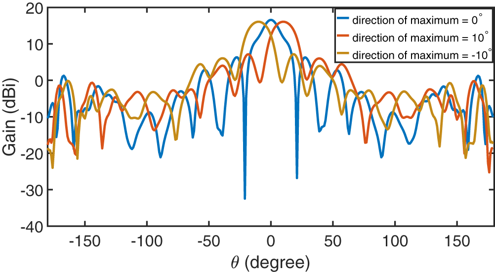
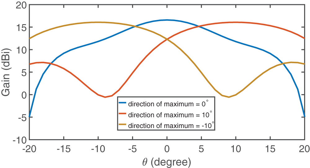
In the present work, five consecutive facets of the conformal array are exploited in the beamforming operation. Every facet is separated by a circular rotation of 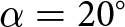 $\alpha = 20^{\circ} $. The middle facet among these five is excited to get the EEP $\vec{F_0}$, whereas the existence of the two adjacent facets confirms that mutual coupling effects are properly accounted for in the research. By using the concept of adaptive tapering in an array, $\gamma_i= \left|{F_0}{(\theta_0-i\alpha)}\right|$ is chosen to modulate each facet’s signal based on its EEP magnitude in the intended scan direction $\theta_0$. This choice mitigates the fundamental challenges of conformal geometries, where facets at angular separation ( $\alpha$ = 20 deg.) show uneven radiation toward $\theta_0$, potentially creating interference, and by proportionally weighting contributions, enhancing the contribution of well-aligned facets while attenuating that of facets with low directivity. The beam can be directed over a sector segment from $-\alpha/2$ to $\alpha/2$ around the broad side, which corresponds to a steering angle of $-10$ to $10$ deg. in this configuration. A maximum gain variation of 0.5 dB is detected across the beams directed in the desired directions, showing a comparatively stable main-lobe amplitude. Furthermore, the SLL is 10.27 dB below the main beam, showing a slightly improvement over previous work [Reference Kumar and Craeye20]. This reduction in the SLL shows better mitigation of unwanted radiation, leading to improved beam directivity and total antenna performance. Although the array has a conformal configuration, the comparatively high sidelobes can be attributed to remaining grating lobes that are not fully suppressed by the narrow EEP [Reference Dessy, Bodehou, Cavillot and Craeye25]. In spite of this, the main lobe pattern remains highly unaffected by beam rotation, retaining good directional results. Figure 10 portrays the three steered beams corresponding to $-10$, $0$, and $10$ deg., highlighting the array’s beamforming potential. Figure 11 shows a zoomed-in view of the steered beams around the broadside region, clearly demonstrating steered beams at $_$10, 0, and 10 deg.
Steered beams in the chosen direction.

Zoomed view of the steered beams around the main lobe.

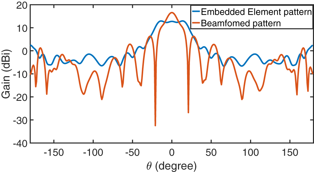
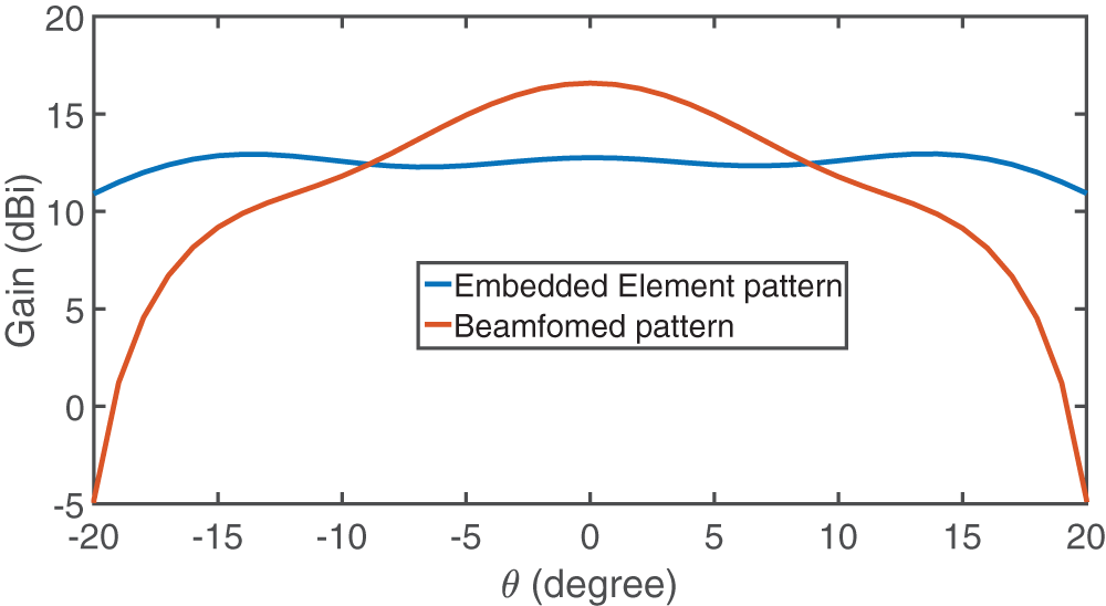
Thus, the presented antenna is able to perform sequential beam scanning with circular polarization over a total coverage angle of  $20$ deg. To achieve a wider angular sector, beamforming is implemented for the next set of facets, allowing for steady and uniform beam steering across the required directions. Figure 12 shows a comparative plot of the EEP and the beamformed pattern when the maximum is oriented at $0$ deg. The beamforming is normalized by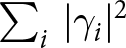 $\sum_i \,|\gamma_i|^2 $ to confirm the comparison of patterns under equal input power conditions. Figure 13 represents a zoomed-in comparison of the EEP and beamformed pattern around the broadside direction, showing a clear demonstration of peak alignments and relative gain differences.
Comparison between EEP and beamformed pattern in the chosen direction of maximum =  $0^{\circ}$.

Zoomed view of the EEP and beamformed pattern near broadside.

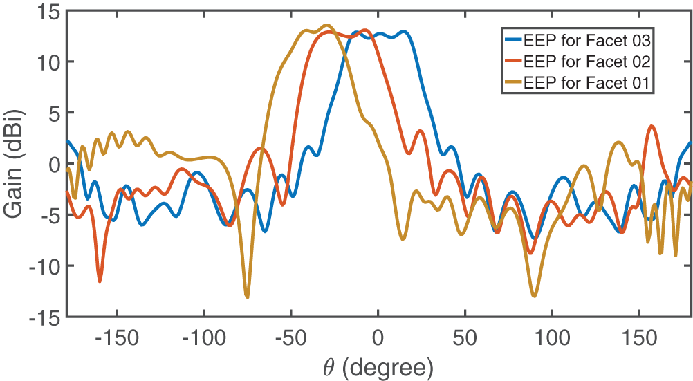
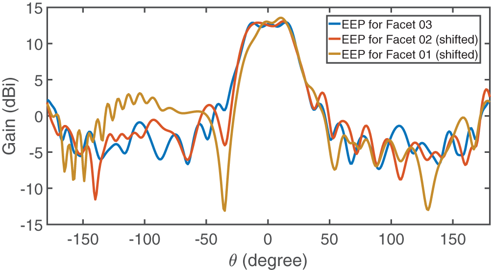
The EEPs of the middle facet (Facet 03) and its adjacent facets (Facets 02 and 01 ) are plotted in Figure 14. The EEPs of the three adjacent facets in the five-facet arrangement are plotted in Figure 15. The obtained plot shows that the difference in the EEPs between Facet 03 and Facet 02 is noticeably lower than that between Facet 03 and Facet 01. Furthermore, a noticeable distortion appears in EEP of Facet 01. This result confirms that the middle facet’s EEP closely resembles the behavior of a large array configuration, demonstrating negligible truncation effects. Given this full-wave approach, the effects of mutual coupling are quite fully accounted for.
EEP of three consecutive facets in a five-facet configuration.

EEPs of three consecutive facets in a five-facet configuration, superimposed and referenced to the middle facet.

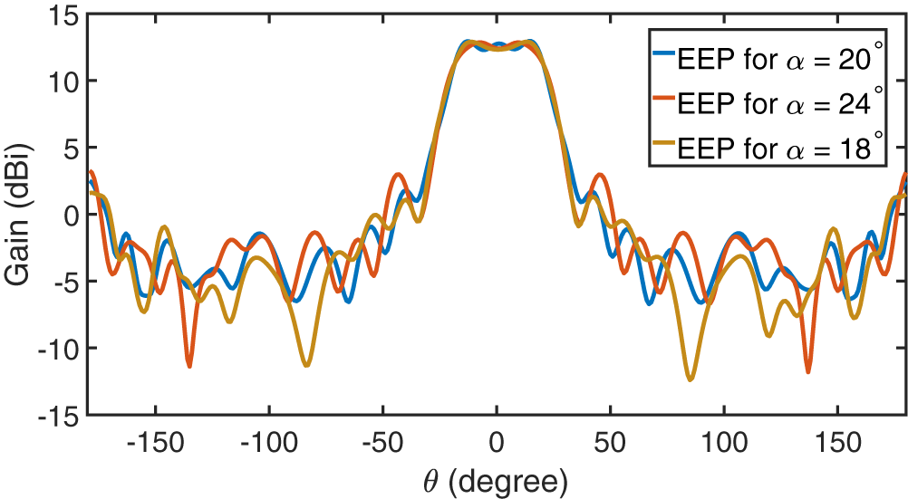
Figure 16 shows the EEPs for different effects of  $\alpha$. This graph gives a comprehensive understanding of $\alpha$ on the overall characteristics. The effects of mutual coupling are fully incorporated in the EEPs. These EEPs were obtained using a large enough number (five facets), ensuring the center element EEP is sufficiently representative of the behavior expected in a fully circular configuration. Also, the EEPs have a flat top, which can be used for the removal of grating lobes and uniform coverage [Reference Dessy, Bodehou, Cavillot and Craeye25].
EEP of the middle facet for three  $\alpha$ variations in a five-facet array configuration.

The weighting factor  $\gamma$ can be justified by the maximum ratio transmission (MRT) principle [Reference Lo26], which is discussed here in the following steps.
Step 1: Identification of channel gain with the PRS array
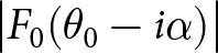
In this case, the channel gain from the  $i_{th}$ facet antenna in the scan direction $\theta_0$ is given by its EEP evaluated at the effective angle $\theta_{eff}$ =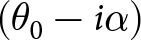 $(\theta_0 - i\alpha)$ shifted by the facet position:
 \begin{equation}
h_i = F_0(\theta_0 - i\alpha)
\end{equation}
\begin{equation}
h_i = F_0(\theta_0 - i\alpha)
\end{equation} \begin{equation}
\qquad\qquad= \big|F_0(\theta_0 - i\alpha)\big| \, e^{j \varphi_0(\theta_0 - i\alpha)}.
\end{equation}
\begin{equation}
\qquad\qquad= \big|F_0(\theta_0 - i\alpha)\big| \, e^{j \varphi_0(\theta_0 - i\alpha)}.
\end{equation}Here,
• $\big|F_0(\theta_0 - i\alpha)\big|$: magnitude of the EEP (radiation strength),
•
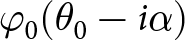
$\varphi_0(\theta_0 - i\alpha)$: corresponding phase of the element pattern.
Step 2: Construction of MRT weight. The transmit weight for facet  $i$ is
 \begin{equation}
w_i = \frac{\left| F_0(\theta_0 - i \alpha) \right| e^{-j \varphi_0(\theta_0 - i \alpha)}}{\sqrt{\sum_{i=1}^N \left| F_0(\theta_0 - i \alpha) \right|^2}}
\end{equation}
\begin{equation}
w_i = \frac{\left| F_0(\theta_0 - i \alpha) \right| e^{-j \varphi_0(\theta_0 - i \alpha)}}{\sqrt{\sum_{i=1}^N \left| F_0(\theta_0 - i \alpha) \right|^2}}
\end{equation}Step 3: Equal power allocation. In this case, equal power weights:
 \begin{equation}
\mathbf{w}_{\text{eq}} = \frac{1}{\sqrt{N}}\mathbf{P}
\end{equation}
\begin{equation}
\mathbf{w}_{\text{eq}} = \frac{1}{\sqrt{N}}\mathbf{P}
\end{equation} In case of  $\theta_0$ = 5 deg., the signal-to-noise ratio (SNR) MRT, $\text{SNR}_{\text{MRT}}$ is found to be 3.41 dB larger than obtained with SNR equal weighting ( $\text{SNR}_{\text{eq}}$ ). This increased performance leads to a clear justification for choosing the weighting factor $\gamma_i$.
Even though FPC antennas based on PRSs have been exhaustively researched for gain enhancement, polarization change, and beam shaping, research explicitly focused on multifaceted PRS structures remains limited in the publicly accessible papers. Most available studies primarily address planar cavity topology and single facet arrangement, in which gain and bandwidth enhancement and polarization change are achieved through single-layer [Reference Liu and Lu14–Reference De, Abegaonkar and Basu18] and multilayer [Reference Konstantinidis, Feresidis and Hall19] designs. Hence, the continuation of these ideas to multifaceted structures is proposed.
Thanks to the non-planar arrangement of the proposed design and the beamforming weight, it significantly enhances performance. This arrangement achieves a maximum gain of 16.1 dBi, which is higher than the maximum gain reported in [Reference Ji, Guo, Qin, Gong and Mittra27] (14 dBi), [Reference Ji, Qin, Li and Zhang28] (12.3 dBi), and the directivity of 14.8 dBi in [Reference Ourir, Burokur and De Lustrac29]. In contrast, dual-sided [Reference Orr, Goussetis and Fusco16] and three-layer [Reference Konstantinidis, Feresidis and Hall19] PRS configurations report gains of 21.1 and 20 dBi, respectively. However, scanning capability is not addressed in [Reference Orr, Goussetis and Fusco16] and [Reference Konstantinidis, Feresidis and Hall19]. Furthermore, the design offers higher stability, while [Reference Ji, Guo, Qin, Gong and Mittra27] and [Reference Ji, Qin, Li and Zhang28] exhibit gain fluctuation of 2.5 and 0.8 dBi; the gain variation of this structure is limited to 0.5 dBi. Regarding the scanning, the design archives scanning from  $-\alpha/2$ to $\alpha/2$; a wider range is not required, as subsequent facets and their neighboring facets cover further angles. This is different from planar structures [Reference Ji, Guo, Qin, Gong and Mittra27, Reference Ji, Qin, Li and Zhang28], which, by nature, need to scan wider angles.
Conclusion
A high-gain multifaceted CP antenna array using a PRS has been designed and investigated using CST Microwave Studio for satellite communication applications. The microstrip patch antennas are LP, which is converted to circular polarization via sequential excitation of the source with a  $90$ deg. phase difference. The beamforming method is applied using phase correction, where the inter-element phases are properly tuned to establish constructive interference of radiated fields in the required direction. Moreover, a weighting function is added, proportional to the EEP magnitude in the given direction (MRT), to appropriately include the variation in element radiation properties and mitigate unwanted contributions from facets with lower power towards the beamforming direction. In practice, EEPs have been obtained from a five-facet configuration in which the middle element is only excited. This unified method achieves high-gain performance and provides effective beam detection over the coverage area, while strongly reducing residual grating lobes.
Using the EEPs, the array pattern has been effectively scanned across the angular region occupied by consecutive facets, in this case from  $-10$ to $10$ deg. Within this field of view, the antenna pattern shows notable stability, with a maximum gain deviation maintained at 0.5 dB. Additionally, a side lobe level of 10.27 dB with respect to the main beam is achieved, which, despite being moderate, still demonstrates improved suppression of unwanted radiation. Hence, these results show the beam control over the sector defined by individual facets, while account for coupling with neighboring facets.
The use of cylindrical arrays allows the natural combination of beamforming and beam switching. The beamforming strategy of such a configuration is introduced, for which this paper offers a first insight. Future work will focus on the corresponding beamforming circuit.
Funding statement
This work is carried out as part of the Space4ReLaunch project, funded by the SPW Economie Emploi Recherche of the Walloon Region through grant no. 2210181.
Competing interests
The author(s) declare none.

Vivek Kumar received his Bachelor of Engineering degree from Jai Narain Vyas University, Jodhpur, India, in 2017, and his Master of Science (by Research) from the Indian Institute of Technology Guwahati, India, in 2021. He is currently pursuing a Ph.D. degree in Electrical Engineering at UCLouvain. His current research interests include conformal phased antennas, partially reflecting surfaces, and metasurface antennas. He is a Graduate Student Member of IEEE and IEEE Microwave Theory & Technology Society.

Christophe Craeye received the Electrical Engineering degree in 1994 and the Ph.D. degree in microwave remote sensing in 1998, both from Universite catholique de Louvain (UCLouvain), Louvain-la-Neuve, Belgium. From 1999 to 2001, he stayed as a post-doc researcher in The Netherlands, in the framework of the Square Kilometer Array radio telescope project. He is currently a professor at UCLouvain. His research topics are multiple-antenna systems and metamaterials. Dr. Craeye served as an Associate Editor for several IEEE journals between 2004 and 2017.




 Open access

