


1 Introduction
Fiber lasers are extensively employed in diverse fields, including industrial processing, energy exploration, medical treatment and scientific research[ Reference Richardson, Nilsson and Clarkson1– Reference Shiner4]. These applications typically demand high power and excellent beam quality. However, power scaling in ytterbium-doped fiber lasers is primarily constrained by nonlinear effects and transverse mode instability (TMI)[ Reference Dong, Ballato and Kolis5, Reference Zervas6]. In recent years, conventional large-mode-area (LMA) fibers with a step-index profile have been widely used as a gain medium in high-power fiber lasers to reduce the influence of nonlinear effects, especially stimulated Raman scattering (SRS), and achieve high-power output laser[ Reference Chen, Yao, Huang, An, Wu, Pan and Zhou7]. However, LMA fibers with a larger core diameter can support more high-order modes (HOMs), which would result in beam quality degradation and a lower TMI threshold. Therefore, it is difficult to simultaneously achieve high power and good beam quality. To balance the SRS suppression and TMI mitigation, various specialty optical fibers have been proposed, such as long-tapered fibers[ Reference Filippov, Chamorovskii, Kerttula, Golant, Pessa and Okhotnikov8– Reference Zeng, Xi, Ye, Lin, Wang, Li, Shi, Yang, Zhang, Wang, Zhou and Xu10], low-numerical-aperture (NA) fibers[ Reference Chen, Ye, Huang, Yang, Wu, Yan, Pan, Wang, Wang and Zhou11– Reference Beier, Hupel, Nold, Kuhn, Hein, Ihring, Sattler, Haarlammert, Schreiber, Eberhardt and Tünnermann13], large-pitch fibers[ Reference Stutzki, Jansen, Eidam, Steinmetz, Jauregui, Limpert and Tünnermann14– Reference du Jeu, Dauliat, Leconte, Malleville, Jamier, Bierlich, Schwuchow, Schuster and Roy16], photonic crystal fibers[ Reference Ying, Yan, Shan, Gao, Si, Fu and Qi17– Reference Dong, Kong, Gu, Hawkins, Jones and Parsons19] and confined-doped fibers[ Reference Wu, Li, An, Li, Chen, Xiao, Huang, Yang, Yan, Leng, Pan and Zhou20– Reference Huang, Wu, Li, Xiao, Yang, Yan, Leng, Pan and Zhou22], among which, the confined-doped fiber is easier to implement and has proven its capability in high-brightness fiber laser generation[ Reference Mashiko, Nguyen, Kashiwagi, Kitabayashi, Shima and Tanaka23– Reference Ye, Koponen, Kokki, Montiel i Ponsoda, Tervonen and Honkanen29].
The confined-doped fiber is designed to provide preferential gain to the expected transverse modes by selective doping within the core, which is known as the gain-filtering effect[
Reference Marciante30]. In confined-doped fibers, usually the center of the core is doped; since the fundamental mode (LP ${}_{01}$
) mainly occupies the central region of the core, it can extract more gain and thus dominate the output laser. In terms of near-single-mode operation (beam quality factor M
${}_{01}$
) mainly occupies the central region of the core, it can extract more gain and thus dominate the output laser. In terms of near-single-mode operation (beam quality factor M ${}^2<1.5$
), in 2016, Mashiko et al. [
Reference Mashiko, Nguyen, Kashiwagi, Kitabayashi, Shima and Tanaka23] from Fujikura reported a 2 kW bidirectional-pump confined-doped oscillator with beam quality factor M
${}^2<1.5$
), in 2016, Mashiko et al. [
Reference Mashiko, Nguyen, Kashiwagi, Kitabayashi, Shima and Tanaka23] from Fujikura reported a 2 kW bidirectional-pump confined-doped oscillator with beam quality factor M ${}^2$ $\sim$
1.2. By optimizing the pump power allocation, the output power was further improved to 3 kW with M
$\sim$
1.2. By optimizing the pump power allocation, the output power was further improved to 3 kW with M ${}^2\sim$
1.3[
Reference Ikoma, Nguyen, Kashiwagi, Uchiyama, Shima and Tanaka24], proving the great potential of the confined-doped fiber in power scaling and beam quality maintenance. In 2022, Zhang et al. [
Reference Zhang, Lin, Zhang, Luo, Liao, Wang, Chen, Xing, Li, Peng, Dai, Zhou and Li31] demonstrated a bidirectional-pumped all-fiber amplifier, of which a 4.18-kW single-mode (M
${}^2\sim$
1.3[
Reference Ikoma, Nguyen, Kashiwagi, Uchiyama, Shima and Tanaka24], proving the great potential of the confined-doped fiber in power scaling and beam quality maintenance. In 2022, Zhang et al. [
Reference Zhang, Lin, Zhang, Luo, Liao, Wang, Chen, Xing, Li, Peng, Dai, Zhou and Li31] demonstrated a bidirectional-pumped all-fiber amplifier, of which a 4.18-kW single-mode (M ${}^2$ $\sim$
1.3) laser output is achieved by employing a low-NA confined-doped long-tapered Yb-doped fiber. As for confined-doped fiber lasers with higher output power, the tandem pumping scheme is mostly employed and the beam qualities deviate from near-single mode. In 2018, Seah et al. [
Reference Seah, Lim and Chua25] built a tandem-pumped fiber amplifier using confined-doped fiber with 4.1 kW output power and M
$\sim$
1.3) laser output is achieved by employing a low-NA confined-doped long-tapered Yb-doped fiber. As for confined-doped fiber lasers with higher output power, the tandem pumping scheme is mostly employed and the beam qualities deviate from near-single mode. In 2018, Seah et al. [
Reference Seah, Lim and Chua25] built a tandem-pumped fiber amplifier using confined-doped fiber with 4.1 kW output power and M ${}^2$ $\sim$
1.59, which was much better than its full-doped fiber amplifier counterpart. In 2022, Wu et al. [
Reference Wu, Li, Xiao, Huang, Yang, Leng, Pan and Zhou32] fabricated a confined-doped fiber with the core/cladding diameter of 40/250 μm and doping ratio of approximately 75%. Based on a bidirectional tandem-pumped amplifier, 7.88 kW output power was realized with the beam quality factor of M
$\sim$
1.59, which was much better than its full-doped fiber amplifier counterpart. In 2022, Wu et al. [
Reference Wu, Li, Xiao, Huang, Yang, Leng, Pan and Zhou32] fabricated a confined-doped fiber with the core/cladding diameter of 40/250 μm and doping ratio of approximately 75%. Based on a bidirectional tandem-pumped amplifier, 7.88 kW output power was realized with the beam quality factor of M ${}^2$ $\sim$
1.97. Later that year, they improved the output power to over 10 kW with M
$\sim$
1.97. Later that year, they improved the output power to over 10 kW with M ${}^2$ $\sim$
2.16[
Reference Huang, Wu, Li, Xiao, Yang, Yan, Leng, Pan and Zhou22], which is the highest power confined-doped fiber laser ever reported.
$\sim$
2.16[
Reference Huang, Wu, Li, Xiao, Yang, Yan, Leng, Pan and Zhou22], which is the highest power confined-doped fiber laser ever reported.
Based on the above-mentioned experimental results, it can be recognized that achieving higher output power while maintaining near-single-mode beam quality in confined-doped fibers presents a significant challenge. Examining the operation mechanism of confined-doped fibers, it is evident that these fibers are designed to confer preferential gain to specific transverse modes, rather than incurring preferential loss across different modes, indicating that the inevitably generated HOMs at the fiber splicing point would experience power amplification in the confined-doped fiber. Therefore, the proportion of HOMs in the output laser is largely determined by the doping ratio. In the above-mentioned fiber lasers, the doping ratio is larger than the optimum value (typically $\sim$
0.5) in order to guarantee sufficient pump absorption with a short fiber length. Therefore, the HOMs would extract considerable gain and degrade the beam quality, making it extremely hard to realize near-single-mode laser operation. While reducing the doping ratio can suppress the amplification of HOMs, this approach inherently compromises pump absorption efficiency. Balancing beam quality maintenance, pump efficiency and power scalability therefore represents a critical challenge in high-power fiber laser design.
$\sim$
0.5) in order to guarantee sufficient pump absorption with a short fiber length. Therefore, the HOMs would extract considerable gain and degrade the beam quality, making it extremely hard to realize near-single-mode laser operation. While reducing the doping ratio can suppress the amplification of HOMs, this approach inherently compromises pump absorption efficiency. Balancing beam quality maintenance, pump efficiency and power scalability therefore represents a critical challenge in high-power fiber laser design.
To address this challenge, a promising strategy involves introducing discriminative loss mechanisms specifically targeting HOMs. A direct and practical approach to achieve this is through the incorporation of a low-NA fiber design. By reducing mode confinement, such a configuration enhances bending-induced loss for HOMs even at relatively large bending diameters, effectively suppressing their amplification without inducing significant perturbations to the fundamental mode. This approach leverages the inherent sensitivity of HOMs to geometric perturbations. The feasibility, implementation methodology and performance efficacy of this design warrant systematic investigation to validate its potential for scalable high-power fiber laser systems.
In this study, we proposed the fiber design simultaneously integrating the low optical confinement (low-NA design) and spatially tailored gain distribution (confined-doping design), where the theoretical analysis was carried out to distinguish the benefits of low-NA design and confined-doped design for TMI mitigation, and consequently a low-NA confined-doped fiber with a core/cladding diameter of 26/400 μm was successfully fabricated, with a Yb-ion doping diameter ratio of approximately 75% and core NA of 0.045. As a result, a 6.74 kW output power with the beam quality M ${}^2$
factor of approximately 1.49 is demonstrated based on the self-developed specialty fiber in a bidirectional laser diode (LD) pump scheme.
${}^2$
factor of approximately 1.49 is demonstrated based on the self-developed specialty fiber in a bidirectional laser diode (LD) pump scheme.
2 Theoretical analysis
Previous study shows that confined-doped fibers with a relative doping ratio of less than 0.6 have the potential to achieve single-mode fiber laser output, which, however, requires excessively long fiber lengths for sufficient pump absorption, and the power scaling would be limited by the SRS effect[
Reference Wu, Li, Xiao, Huang, Yang, Pan, Leng and Zhou21]. Increasing the relative doping ratio would increase the overlap between HOMs and the doped region, which weakens the gain-filtering effect, leading not only to beam quality degradation but also to a reduction in the TMI threshold. To balance the mitigation of the SRS effect and the TMI effect in confined-doped fiber with a doping ratio being larger than the optimum value, we integrate the low-NA design into the confined-doped fibers as an alternative to the conventional low-doping-ratio gain fibers to facilitate near-single-mode operation. To assess the feasibility of the proposed scheme, the TMI thresholds of the two types of fibers are theoretically investigated. We use a TMI theoretical model based on coupled-beam theory to calculate the TMI threshold of the confined-doped fiber amplifier, where the mode coupling equations for the LP ${}_{01}$
mode and LP
${}_{01}$
mode and LP ${}_{11}$
mode can be expressed as follows:
${}_{11}$
mode can be expressed as follows:
 $$\begin{align}\frac{\mathrm{d}P_1}{\mathrm{d}z}=\left({g}_1-{\alpha}_1\right){P}_1-{g}_1\chi {P}_2{P}_1,\end{align}$$
 $$\begin{align}\frac{\mathrm{d}P_2}{\mathrm{d}z}=\left({g}_2-{\alpha}_2\right){P}_2+{g}_1\chi {P}_1{P}_2,\end{align}$$
where subscripts 1 and 2 represent the LP ${}_{01}$
mode and LP
${}_{01}$
mode and LP ${}_{11}$
mode, respectively, P denotes the signal power, g represents the pump gain,
${}_{11}$
mode, respectively, P denotes the signal power, g represents the pump gain, $\alpha$
is the mode loss and
$\alpha$
is the mode loss and $\chi$
is the nonlinear coupling coefficient, derived from Ref. [Reference Ikoma, Nguyen, Kashiwagi, Uchiyama, Shima and Tanaka24]. The power of the LP
$\chi$
is the nonlinear coupling coefficient, derived from Ref. [Reference Ikoma, Nguyen, Kashiwagi, Uchiyama, Shima and Tanaka24]. The power of the LP ${}_{11}$
mode can be expressed as follows:
${}_{11}$
mode can be expressed as follows:
 $$\begin{align}&{P}_2(z)\nonumber\\ &\quad={P}_2(0)\exp\left(\underset{0}{\overset{z}{\int }}\left({g}_2\left({z}^{\prime}\right)-{\alpha}_2\left({z}^{\prime}\right)+{g}_1\left({z}^{\prime}\right)\chi \left({z}^{\prime}\right){P}_1\left({z}^{\prime}\right)\right)\kern0.1em \mathrm{d}{z}^{\prime}\right),\end{align}$$
where P ${}_2$
(0) is the initial power of the LP
${}_2$
(0) is the initial power of the LP ${}_{11}$
mode. The output power at which the power of the LP
${}_{11}$
mode. The output power at which the power of the LP ${}_{11}$
mode reaches 1% of the total power at any position along the fiber is defined as the TMI threshold. A backward pump fiber amplifier is assumed in the simulation, where the core/cladding diameter of the gain fiber is set to 26/400 μm, the pump wavelength is 976 nm and the signal wavelength is 1064 nm. The Yb-doping concentration is 5
${}_{11}$
mode reaches 1% of the total power at any position along the fiber is defined as the TMI threshold. A backward pump fiber amplifier is assumed in the simulation, where the core/cladding diameter of the gain fiber is set to 26/400 μm, the pump wavelength is 976 nm and the signal wavelength is 1064 nm. The Yb-doping concentration is 5 $\times$
10
$\times$
10 ${}^{25}$
m
${}^{25}$
m ${}^{-3}$
, the seed power is 30 W and the bending diameter (2R
b) is set to 30 cm to alleviate the bend-induced mode distortion.
${}^{-3}$
, the seed power is 30 W and the bending diameter (2R
b) is set to 30 cm to alleviate the bend-induced mode distortion.
According to the above theoretical model, the TMI threshold and the overlap integral between the transverse mode and the doped region (the energy proportion of transverse modes in the doped region) are calculated and are illustrated in Figure 1(a). Firstly, the overlap integral in both the bent and unbent states is very close, indicating that the bend-induced mode distortion is negligible. Therefore, the subsequent simulation results do not take into account the effects of bending distortion. When the core NA is 0.06, as the relative doping ratio increases from 0.6 to 0.75, the overlap integral of the LP ${}_{11}$
mode with the doped region increases from 0.33 to 0.58, as shown in Figure 1(a), leading to a decrease in the TMI threshold from 8000 to 4439 W, as shown in Figure 1(b). Upon reducing the core NA to 0.045, the LP
${}_{11}$
mode with the doped region increases from 0.33 to 0.58, as shown in Figure 1(a), leading to a decrease in the TMI threshold from 8000 to 4439 W, as shown in Figure 1(b). Upon reducing the core NA to 0.045, the LP ${}_{11}$
mode exhibits increased lateral spread owing to the lower mode confinement, the overlap integral of the LP
${}_{11}$
mode exhibits increased lateral spread owing to the lower mode confinement, the overlap integral of the LP ${}_{11}$
mode with the doped region decreases from 0.58 to 0.45 and the TMI threshold of the confined-doped fiber amplifier with a relative doping ratio of 0.75 increases to 5114 W. It is noteworthy that in the above analysis, the HOM losses are disregarded, and the assessment is focused solely on the impact of the overlap factor change induced by the NA change. The results indicate that the low-NA design can reduce the overlap factor between the LP
${}_{11}$
mode with the doped region decreases from 0.58 to 0.45 and the TMI threshold of the confined-doped fiber amplifier with a relative doping ratio of 0.75 increases to 5114 W. It is noteworthy that in the above analysis, the HOM losses are disregarded, and the assessment is focused solely on the impact of the overlap factor change induced by the NA change. The results indicate that the low-NA design can reduce the overlap factor between the LP ${}_{11}$
mode and the doping region, therefore making it less demanding on the doping diameter.
${}_{11}$
mode and the doping region, therefore making it less demanding on the doping diameter.
The impact of the NA and relative doping ratio on the (a) overlap integral of the LP ${}_{01}$
mode (solid line) and the LP
${}_{01}$
mode (solid line) and the LP ${}_{11}$
mode (dashed line) and (b) the TMI threshold.
${}_{11}$
mode (dashed line) and (b) the TMI threshold.
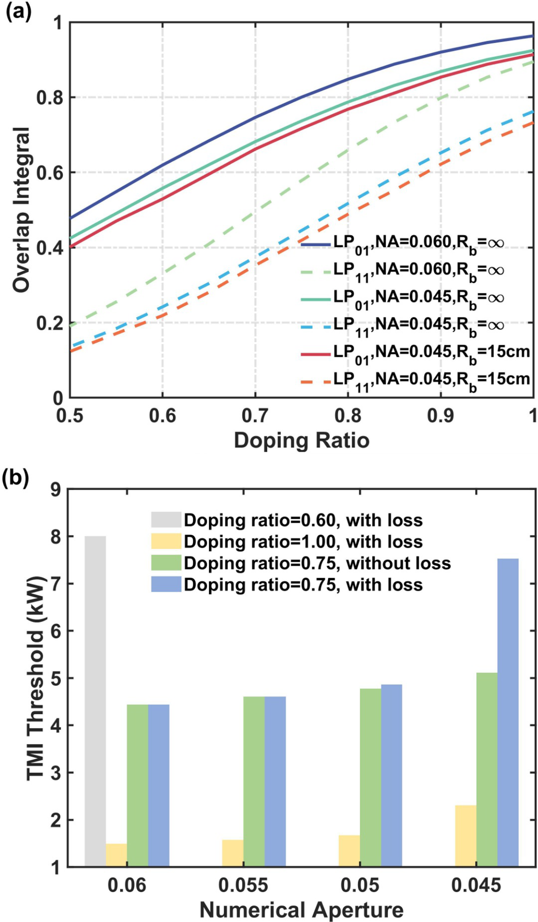
Further considering the additional increment in bending loss (2.1 dB/m for the LP ${}_{11}$
mode, neglectable bending loss for the LP
${}_{11}$
mode, neglectable bending loss for the LP ${}_{01}$
mode) attributed to the diminished NA of 0.045, the TMI threshold is ultimately elevated to 7524 W, as shown in Figure 1(b). The TMI threshold of confined-doped fibers with a core NA of approximately 0.045 and a relative doping ratio of 0.75 is comparable to that of confined-doped fiber with a core NA of approximately 0.06 and a relative doping ratio of 0.6. Therefore, the high bending loss for HOMs brought about by the low-NA design can also contribute to TMI mitigation.
${}_{01}$
mode) attributed to the diminished NA of 0.045, the TMI threshold is ultimately elevated to 7524 W, as shown in Figure 1(b). The TMI threshold of confined-doped fibers with a core NA of approximately 0.045 and a relative doping ratio of 0.75 is comparable to that of confined-doped fiber with a core NA of approximately 0.06 and a relative doping ratio of 0.6. Therefore, the high bending loss for HOMs brought about by the low-NA design can also contribute to TMI mitigation.
Moreover, to distinguish the TMI mitigation effect of gain filtering from the bending loss in this fiber, the TMI thresholds of the fiber amplifier employing the conventional fully doped fiber with the same core and cladding diameter are calculated. As shown in Figure 1(b), a fiber amplifier based on the conventional fiber with a core NA of 0.045 has the TMI threshold of 2307 W, which is only approximately 31% of the amplifier employing confined-doped fiber with a doping ratio of 0.75, indicating that the gain-filtering effect brought about by the confined-doping design also plays a significant role in TMI mitigation.
Therefore, by reducing the core NA, the confined-doped fiber with a relatively high doping ratio can achieve comparable performance to confined-doped fiber with the optimum doping ratio (usually a low doping ratio of $\sim$
0.6), which brings new insights into the design of high-performance confined-doped fiber for near-single-mode laser operation.
$\sim$
0.6), which brings new insights into the design of high-performance confined-doped fiber for near-single-mode laser operation.
3 Fiber characterization and experimental setup
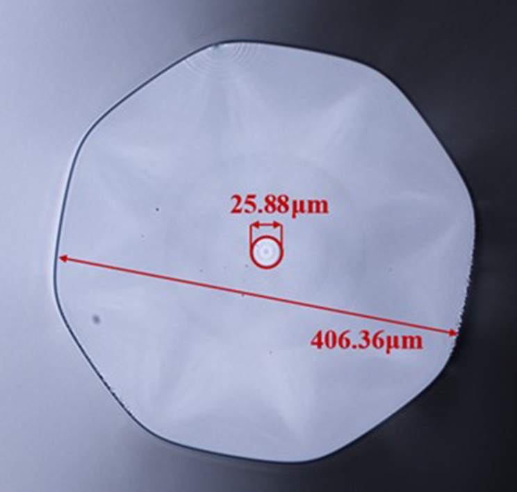
Based on the theoretical investigation of the individual and combined effects of low NA and confined doping on the TMI threshold, a low-NA confined-doped fiber with a core/cladding diameter of 26/400 μm is designed and fabricated. The cross-section of the developed fiber is shown in Figure 2, implying a core diameter of approximately 25.88 μm and a cladding diameter of approximately 406.36 μm. The confined-doped fiber preform rod is made based on the modified chemical vapor deposition (MCVD) process combined with rare earth chelate compound gas-phase doping technology. The core layer of the fiber preform consists of eight layers. The inner five layers are composed of SiO ${}_2$
, Yb
${}_2$
, Yb ${}_2$
O
${}_2$
O ${}_3$
, P
${}_3$
, P ${}_2$
O
${}_2$
O ${}_5$
, Al
${}_5$
, Al ${}_2$
O
${}_2$
O ${}_3$
and SiF
${}_3$
and SiF ${}_4$
. The composition of the outer three core layers is SiO
${}_4$
. The composition of the outer three core layers is SiO ${}_2$
, Al
${}_2$
, Al ${}_2$
O
${}_2$
O ${}_3$
and SiF
${}_3$
and SiF ${}_4$
. After the eight-layer core layer deposition is completed, the hollow preform needs to be collapsed into a solid preform through a high-temperature rod shrinking process. The weight percentage distribution of F, Al
${}_4$
. After the eight-layer core layer deposition is completed, the hollow preform needs to be collapsed into a solid preform through a high-temperature rod shrinking process. The weight percentage distribution of F, Al ${}_2$
O
${}_2$
O ${}_3$
, P
${}_3$
, P ${}_2$
O
${}_2$
O ${}_3$
and Yb
${}_3$
and Yb ${}_2$
O
${}_2$
O ${}_3$
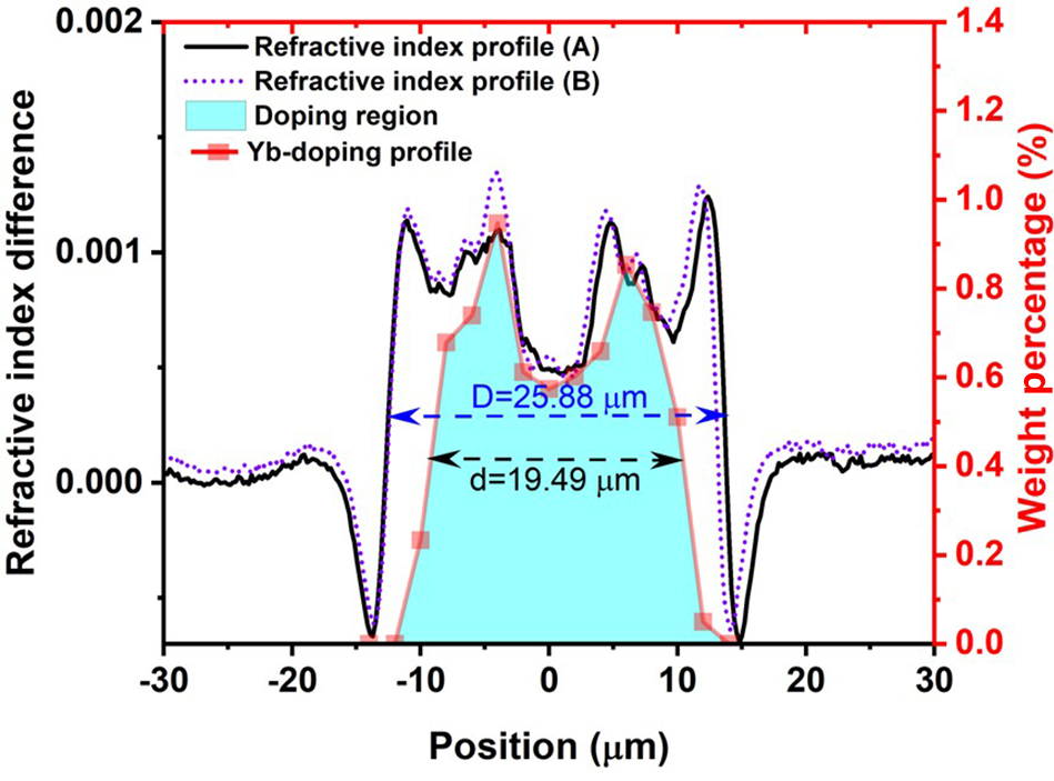
of the confined-doped fiber (derived from an electron probe micro analyzer) is shown in Figure 3. Figure 4 shows the refractive index profiles at two positions (A and B) along the fiber, spaced approximately 20 m apart, as well as the weight percentage distribution of Yb
${}_3$
of the confined-doped fiber (derived from an electron probe micro analyzer) is shown in Figure 3. Figure 4 shows the refractive index profiles at two positions (A and B) along the fiber, spaced approximately 20 m apart, as well as the weight percentage distribution of Yb ${}_2$
O
${}_2$
O ${}_3$
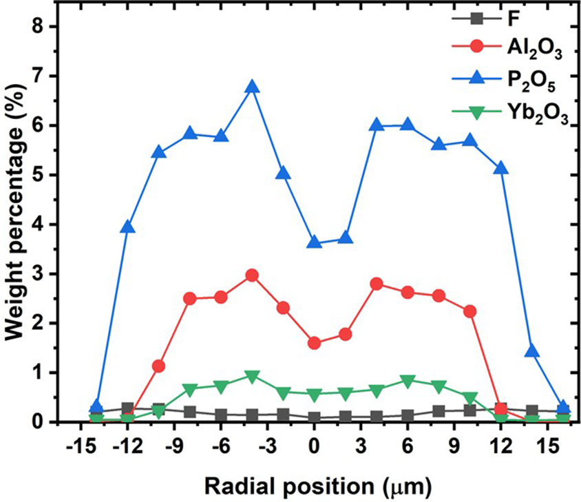
in the confined-doped fiber. The refractive index distributions at these two positions are quite similar, and the fluctuation of the radial refractive index distribution of the fiber is reduced compared with the fiber preform. The core diameter is approximately 25.88 μm and the Yb-ion doping diameter is approximately 19.49 μm, indicating a relative doping ratio of approximately 75.31%. The core NA is approximately 0.045 according to the refractive index profile. However, during the high-temperature rod shrinking process, when the heating temperature reaches above 2200°C, elements such as ytterbium, fluorine and phosphorus in the central core layer will evaporate due to heat, while other core layers are far away from the surface, and elements such as ytterbium, fluorine and phosphorus will not evaporate. The above reasons will result in a more obvious central dip of the refractive index distribution profile and ytterbium concentration distribution profile, as shown in Figure 4. The pump absorption is measured to be approximately 1 dB/m at 976 nm through the cutback method. The attenuation loss of the confined-doped fiber is measured to be approximately 13.5 dB/km at 1200 nm.
${}_3$
in the confined-doped fiber. The refractive index distributions at these two positions are quite similar, and the fluctuation of the radial refractive index distribution of the fiber is reduced compared with the fiber preform. The core diameter is approximately 25.88 μm and the Yb-ion doping diameter is approximately 19.49 μm, indicating a relative doping ratio of approximately 75.31%. The core NA is approximately 0.045 according to the refractive index profile. However, during the high-temperature rod shrinking process, when the heating temperature reaches above 2200°C, elements such as ytterbium, fluorine and phosphorus in the central core layer will evaporate due to heat, while other core layers are far away from the surface, and elements such as ytterbium, fluorine and phosphorus will not evaporate. The above reasons will result in a more obvious central dip of the refractive index distribution profile and ytterbium concentration distribution profile, as shown in Figure 4. The pump absorption is measured to be approximately 1 dB/m at 976 nm through the cutback method. The attenuation loss of the confined-doped fiber is measured to be approximately 13.5 dB/km at 1200 nm.
The cross-section of the developed fiber.
Weight percentage distribution of F, Al ${}_2$
O
${}_2$
O ${}_3$
, P
${}_3$
, P ${}_2$
O
${}_2$
O ${}_3$
and Yb
${}_3$
and Yb ${}_2$
O
${}_2$
O ${}_3$
of the confined-doped fiber.
${}_3$
of the confined-doped fiber.

Refractive index profile and Yb ${}_2$
O
${}_2$
O ${}_3$
weight percentage distribution of the confined-doped fiber.
${}_3$
weight percentage distribution of the confined-doped fiber.
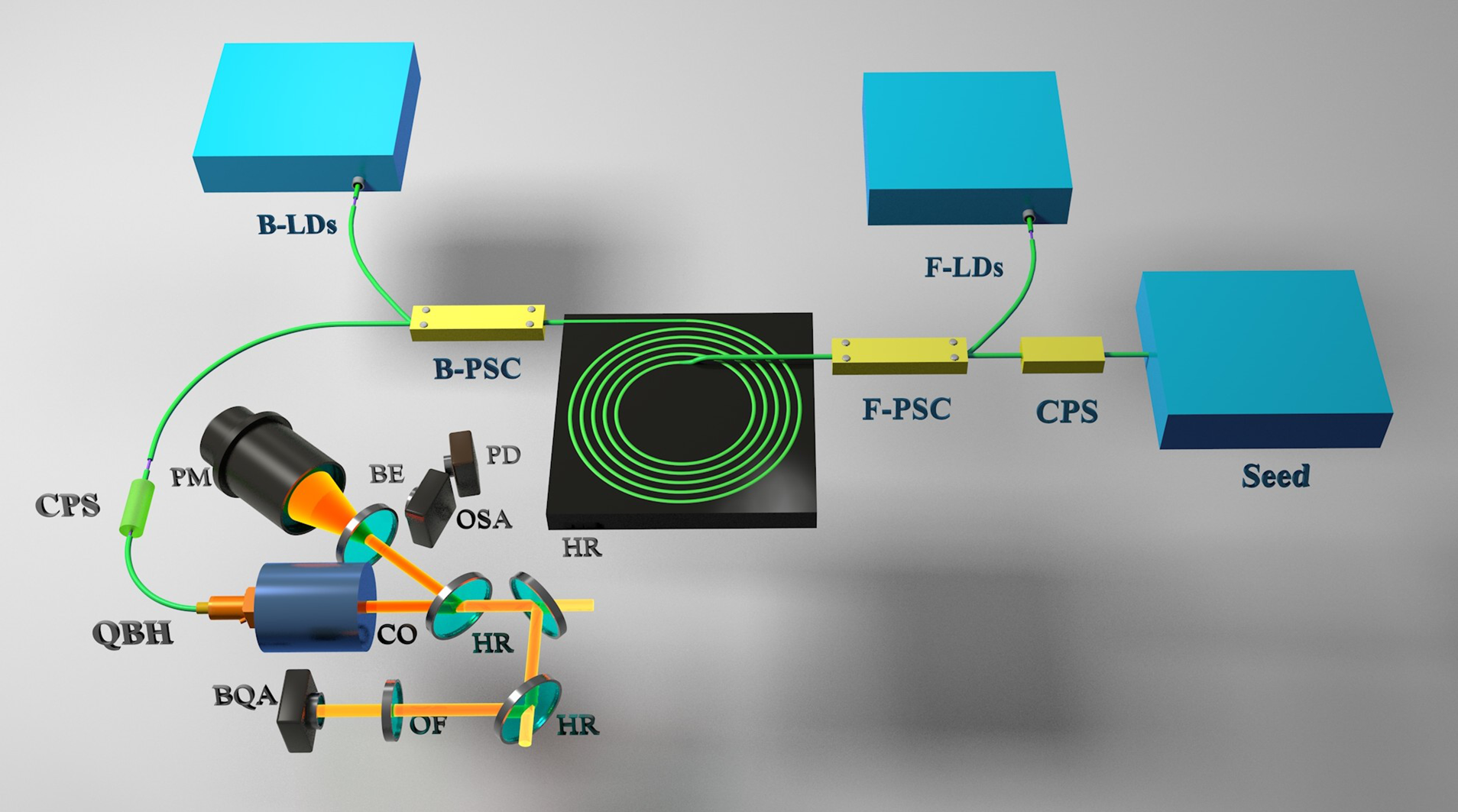
The experimental setup of the bidirectional LD pumped confined-doped fiber amplifier is shown in Figure 5. The seed laser is a 100-W-level fiber laser operating at 1080 nm. To remove the residual pump light from the backward pump, a cladding power stripper (CPS) is adopted before the amplifier stage. The pump sources are based on 976 nm wavelength-stabilized LDs. Four 400-W-level LDs and eleven 250-W-level LDs serve as forward pump sources, while fifteen 400-W-level LDs serve as backward pump sources. All the LDs are injected into the fiber amplifier through the forward and backward (18 + 1) $\times$
1 power and signal combiners (PSCs), which consist of 18 pump ports with a core/cladding diameter of 135/155 μm and a signal fiber with a core/cladding diameter of 30/250 μm. The Yb-doped fiber (YDF) is 20 m in length and is spirally coiled on a water-cooled plate, and the temperature of the water cooling system is set to 20°C, with temperature fluctuation of less than
$\times$
1 power and signal combiners (PSCs), which consist of 18 pump ports with a core/cladding diameter of 135/155 μm and a signal fiber with a core/cladding diameter of 30/250 μm. The Yb-doped fiber (YDF) is 20 m in length and is spirally coiled on a water-cooled plate, and the temperature of the water cooling system is set to 20°C, with temperature fluctuation of less than $\pm$
1°C. The seed laser and the forward pump power enter the fiber amplifier from the innermost circle while the backward pump power enters the fiber amplifier from outmost circle of the gain fiber. Although the core size of the 26/400 μm gain fiber is not optimally matched with that of the 30/400 μm combiner signal fiber, the splice loss between the two fibers is controlled to approximately 0.01 dB by rationally setting the splicing parameters. The amplified laser from the fiber amplifier passes through the CPS and is output via the quartz block head (QBH). All the components are fixed on the water-cooled plates to achieve efficient thermal management. The experimental measurement setup comprises a power meter (PM), an optical spectrum analyzer (OSA), a beam quality analyzer (BQA) and an oscilloscope with a photodetector (PD) to measure the output power, spectra and time domain simultaneously. The output laser is first collimated by the collimator and most of the power is reflected by the high-reflection mirror (HR) and enters the PM for power measurement. The diffracted beam is monitored by the PD and OSA for time-domain and spectrum measurement. The transmitted laser then passes through the optical filter (OF) to filter out the insignificant pump power, and then enters the BQA for beam quality measurement.
$\pm$
1°C. The seed laser and the forward pump power enter the fiber amplifier from the innermost circle while the backward pump power enters the fiber amplifier from outmost circle of the gain fiber. Although the core size of the 26/400 μm gain fiber is not optimally matched with that of the 30/400 μm combiner signal fiber, the splice loss between the two fibers is controlled to approximately 0.01 dB by rationally setting the splicing parameters. The amplified laser from the fiber amplifier passes through the CPS and is output via the quartz block head (QBH). All the components are fixed on the water-cooled plates to achieve efficient thermal management. The experimental measurement setup comprises a power meter (PM), an optical spectrum analyzer (OSA), a beam quality analyzer (BQA) and an oscilloscope with a photodetector (PD) to measure the output power, spectra and time domain simultaneously. The output laser is first collimated by the collimator and most of the power is reflected by the high-reflection mirror (HR) and enters the PM for power measurement. The diffracted beam is monitored by the PD and OSA for time-domain and spectrum measurement. The transmitted laser then passes through the optical filter (OF) to filter out the insignificant pump power, and then enters the BQA for beam quality measurement.
Experimental setup of the bidirectional-pumped confined-doped fiber amplifier. (LD, laser diode; F-PSC, forward pump and signal combiner; B-PSC, backward pump and signal combiner; CPS, cladding power stripper; QBH, quartz block head; CO, collimator; HR, high-reflection mirror; BE, beam expander; OSA, optical spectrum analyzer; OF, optical filter; BQA, beam quality analyzer; PD, photodetector; PM, power meter.)

4 Results and discussion
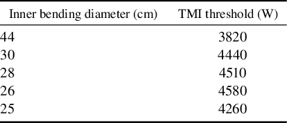
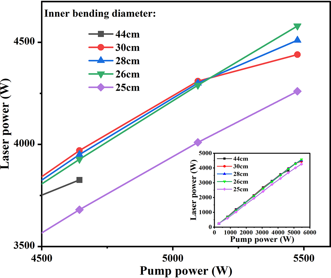
We first conducted a counter-pump experiment to investigate the TMI threshold under various bending diameters. The TMI thresholds of the self-developed YDF with different inner bending diameters (referring to the bending diameter of the innermost circle) under the counter-pump scheme are summarized in Table 1, and the laser power as a function of pump power under different inner bending diameters is shown in Figure 6. When the inner bending diameter decreases from 44 to 26 cm, the TMI threshold exhibits an increasing trend, rising from 3820 to 4580 W. This is attributed to the enhanced bending loss of HOMs, which facilitates a higher TMI threshold. When the inner bending diameter is further decreased to 25 cm, the TMI threshold drops to 4260 W, which is owing to the greater fundamental mode loss at this bending diameter. This can be distinguished from the decreasing overall efficiency from more than 83% to less than 80% at the same pump power. Thus, this fiber amplifier with the inner bending diameter of 26 cm can achieve the highest TMI threshold and, therefore, the bending diameter is fixed at 26 cm throughout the study for further investigation.
The TMI threshold under different inner bending diameters.
Laser power as a function of pump power under different inner bending diameters. Inset: output power within the entire pump power range.
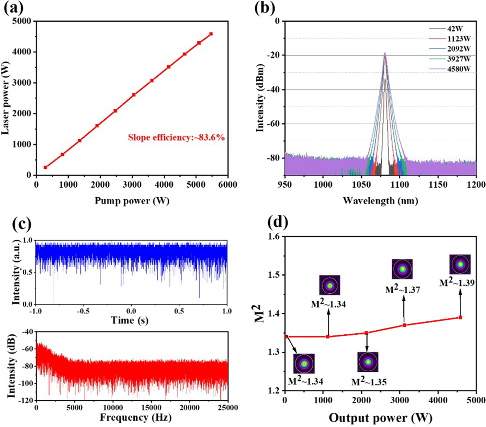
The experimental results at the inner bending diameter of 26 cm are shown in Figure 7. The seed laser power was measured to be approximately 40 W after passing through the amplifier stage. As shown in Figure 7(a), the output power linearly increases with the pump power, with a slope efficiency of approximately 83.6%. When the pump power is 5475 W, the output power reaches 4580 W. There is neither residual pump light nor Stokes light components on the spectrum during the power scaling process, as shown in Figure 7(b). Further increasing the output power results in obvious fluctuations in the time-domain signal, and typical TMI characteristic frequencies are observed in its corresponding fast Fourier transform (FFT) results, as shown in Figure 7(c). The M ${}^2$
factor is measured and recorded throughout the experiment. The M
${}^2$
factor is measured and recorded throughout the experiment. The M ${}^2$
factor as a function of output power is shown in Figure 7(d). When the output power increases from 40 to 4580 W, the M
${}^2$
factor as a function of output power is shown in Figure 7(d). When the output power increases from 40 to 4580 W, the M ${}^2$
factor slightly increases from 1.34 to 1.39, maintaining a near-single-mode beam quality.
${}^2$
factor slightly increases from 1.34 to 1.39, maintaining a near-single-mode beam quality.
(a) Output power as a function of pump power in the counter-pump scheme. (b) Output spectra under different output powers in the counter-pump scheme. (c) Time-domain signal and the corresponding FFT spectrum at 4580 W. (d) M ${}^2$
factor as a function of output power in the counter-pump scheme. Insert: beam profiles at different output powers.
${}^2$
factor as a function of output power in the counter-pump scheme. Insert: beam profiles at different output powers.
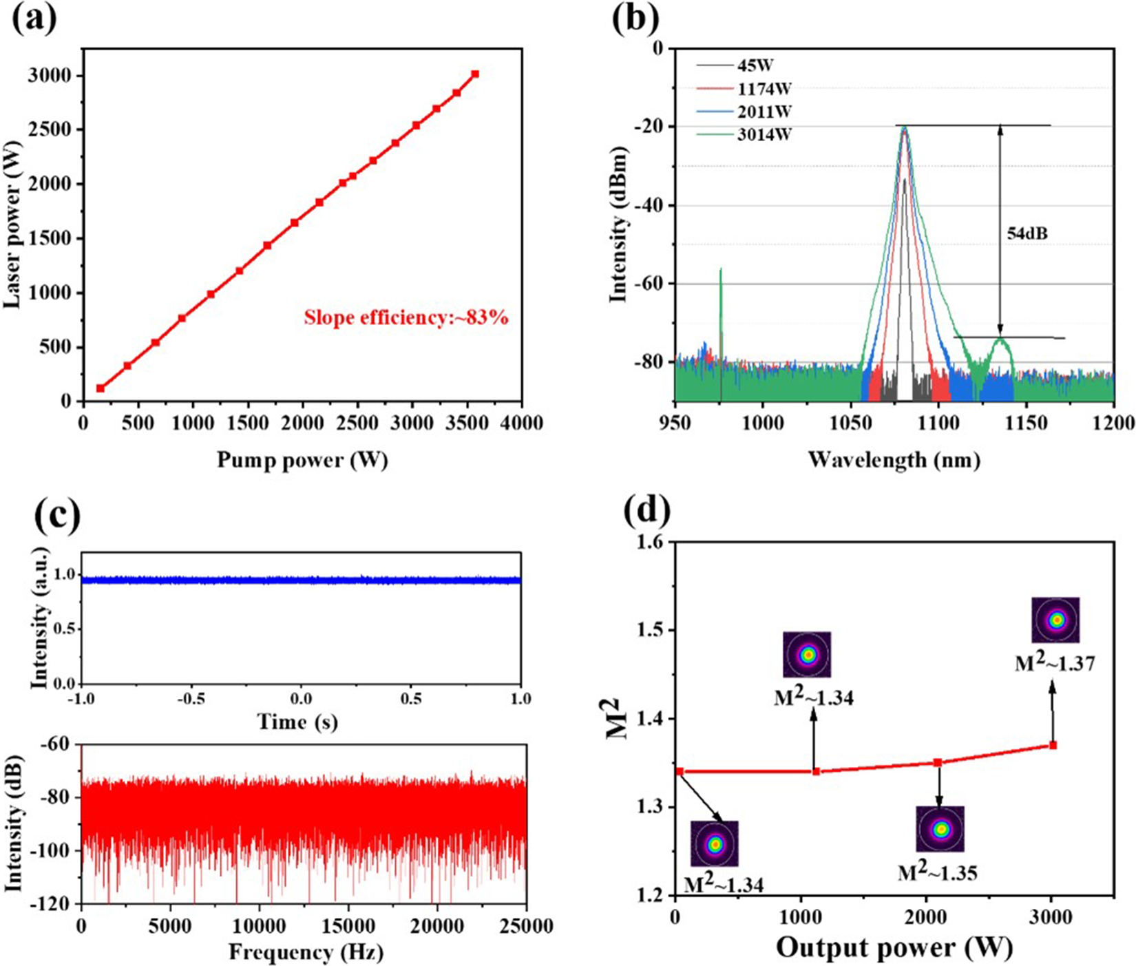
Therefore, the power scaling of this amplifier under the counter-pump condition is limited by TMI, and the threshold is about 4580 W. Then, a co-pump experiment is conducted using three groups of 976 nm LDs, which can provide more than 4 kW pump power. The inner bending diameter of YDF remains at 26 cm, which has the highest TMI threshold under the counter-pump condition. The experimental results are shown in Figure 8. The seed laser power remained at approximately 40 W. As shown in Figure 8(a), the output power linearly increases with the pump power, with a slope efficiency of approximately 83%. When the pump power reaches the maximum of 3573 W, the maximum output power reaches 3014 W. As shown in Figure 8(b), the spectra indicate that the Stokes light component intensity rises up to 54 dB when the output power reaches 3014 W, and the residual pump light intensity is 35 dB lower than the signal light. The time-domain signal detected by the PD and the corresponding FFT results at the output power of 3014 W are shown by the blue and red lines in Figure 8(c). No obvious fluctuations are observed in the time-domain traces, which indicates that the TMI threshold is higher than 3014 W under the co-pump condition by the 976 nm LDs. The measured result of the M ${}^2$
factor and the beam profiles at different output powers are shown in Figure 8(d). When the output power increases from 40 to 3014 W, the M
${}^2$
factor and the beam profiles at different output powers are shown in Figure 8(d). When the output power increases from 40 to 3014 W, the M ${}^2$
factor increases from 1.34 to 1.37 and the beam quality degradation is negligible. The experimental results show that the power scaling of this amplifier is limited by the available pump power, as well as SRS.
${}^2$
factor increases from 1.34 to 1.37 and the beam quality degradation is negligible. The experimental results show that the power scaling of this amplifier is limited by the available pump power, as well as SRS.
(a) Output power as a function of pump power in the co-pump scheme. (b) Output spectra under different output powers in the co-pump scheme. (c) Time-domain signal and the corresponding FFT spectrum at 3014 W. (d) M ${}^2$
factor as a function of output power in the co-pump scheme. Insert: beam profiles at different output powers.
${}^2$
factor as a function of output power in the co-pump scheme. Insert: beam profiles at different output powers.

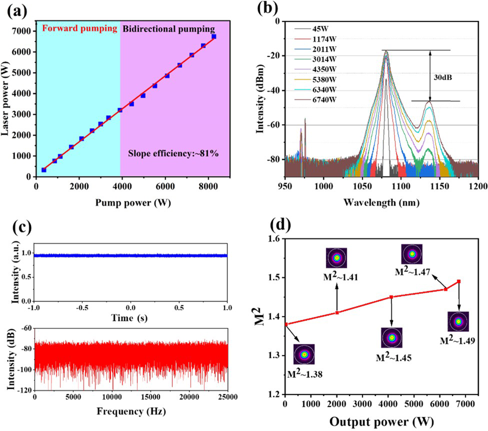
Finally, the amplifier performance was investigated under the bidirectional-pump condition at the same bending diameter. The experimental results are shown in Figure 9. In the bidirectional scheme, the co-pump power is increased to a maximum of 3573 W first, and then the counter-pump power is subsequently increased, as shown in Figure 9(a). The output power increases approximately linearly with the pump power, with a slope efficiency of approximately 81%. When the pump power is 8255 W, the maximum output power reaches 6740 W. The slightly decreased slope efficiency could possibly result from the leaked HOM power owing to degraded beam quality. As shown in Figure 9(b), the SRS suppression ratio is approximately 30 dB under the output power of 6740 W. At the highest output power, no fluctuations appear in the time-domain signal nor its corresponding FFT spectra, as shown in Figure 9(c). The beam quality M ${}^2$
factor is measured and recorded during the experiment; the result and the beam profiles are shown in Figure 9(d). At the highest output power, the M
${}^2$
factor is measured and recorded during the experiment; the result and the beam profiles are shown in Figure 9(d). At the highest output power, the M ${}^2$
factor is approximately 1.49, maintaining a near-single-mode output. When the output power increases from 40 to 6740 W, the M
${}^2$
factor is approximately 1.49, maintaining a near-single-mode output. When the output power increases from 40 to 6740 W, the M ${}^2$
factor increases from 1.37 to 1.49. These results indicate that the TMI threshold of this bidirectional-pump amplifier is higher than 6740 W. The output power and M
${}^2$
factor increases from 1.37 to 1.49. These results indicate that the TMI threshold of this bidirectional-pump amplifier is higher than 6740 W. The output power and M ${}^2$
beam quality factor at the maximum output power exhibited stable performance over multiple consecutive measurements (spanning over 6 min). This consistent behavior demonstrates the system’s operational stability and confirms the absence of TMI effects at the maximum output power. The output power can be further improved by increasing the co-pump power. However, in our case, the overall output power is constrained by the SRS, and further increasing the co-pump power would result in more severe nonlinear effects. Therefore, multiple measures, such as reducing the passive fiber length, should be taken concurrently to realize further power scaling.
${}^2$
beam quality factor at the maximum output power exhibited stable performance over multiple consecutive measurements (spanning over 6 min). This consistent behavior demonstrates the system’s operational stability and confirms the absence of TMI effects at the maximum output power. The output power can be further improved by increasing the co-pump power. However, in our case, the overall output power is constrained by the SRS, and further increasing the co-pump power would result in more severe nonlinear effects. Therefore, multiple measures, such as reducing the passive fiber length, should be taken concurrently to realize further power scaling.
(a) Output power as a function of pump power in the bidirectional-pump scheme. (b) Output spectra under different output powers in the bidirectional-pump scheme. (c) Time-domain signal and the corresponding FFT spectrum at 6740 W. (d) M ${}^2$
factor as a function of output power in the bidirectional-pump scheme. Insert: beam profiles at different output powers.
${}^2$
factor as a function of output power in the bidirectional-pump scheme. Insert: beam profiles at different output powers.
5 Conclusion
To summarize, we proposed a fiber design simultaneously integrating the optical confinement and gain tailoring design for TMI mitigation. The benefits of this fiber design are fully analyzed and recognized, according to which a low-NA confined-doped fiber is developed. Consequently, by exploiting the self-developed low-NA confined-doped fiber, we obtained a 6.74 kW near-single-mode output laser, with a slope efficiency of approximately 81%. At the maximum output power, the SRS suppression ratio is approximately 30 dB and the beam quality M ${}^2$
factor is approximately 1.49. Further power scaling is limited by SRS. To our knowledge, this is the highest output power in a fiber laser employing confined-doped or low-NA fiber design that is delivering near-single-mode beam quality (M
${}^2$
factor is approximately 1.49. Further power scaling is limited by SRS. To our knowledge, this is the highest output power in a fiber laser employing confined-doped or low-NA fiber design that is delivering near-single-mode beam quality (M ${}^2<$
1.5). Further power scaling can be achieved by collaboratively optimizing the doping ratio, dopant distribution uniformity, core NA and refractive index profile. We believe this work could provide a practical and effective approach for achieving higher output power with near-single-mode beam quality in LMA fiber laser systems, and the fabrication simplicity would facilitate scalable deployment in high-brightness laser applications.
${}^2<$
1.5). Further power scaling can be achieved by collaboratively optimizing the doping ratio, dopant distribution uniformity, core NA and refractive index profile. We believe this work could provide a practical and effective approach for achieving higher output power with near-single-mode beam quality in LMA fiber laser systems, and the fabrication simplicity would facilitate scalable deployment in high-brightness laser applications.
Acknowledgements
This work was supported by the National Key Research and Development Program of China (Grant No. 2022YFB3606000), the National Natural Science Foundation of China (Grant Nos. 62305390 and 62205373) and the Distinguished Young Scholars of Hunan Province (Grant No. 2023JJ10057). The authors would like to thank Yangying Zhou and Kun Zhang for their kind help during the experiment.


 Open access