


Introduction
The rapid evolution of wireless communication technologies has led to an ever-increasing demand for antennas that can deliver high performance across multiple frequency bands, with wide bandwidth, stable gain, and robust polarization characteristics [Reference Jan, Kiani, Sehrai, Anjum, Iqbal, Abdullah and Kim1]. In this context, the frequency ranges of 8–16 GHz (microwave) and 24–30 GHz (millimeter-wave, mmWave) have become particularly significant. The 8–16 GHz band, often referred to as the ultra-wideband (UWB) region, is extensively used in radar, imaging, and high-speed broadband wireless communication systems due to its substantial bandwidth and favorable propagation characteristics [Reference Iqbal, Illahi, Ramay and Sulaiman2]. Meanwhile, the 24–30 GHz mmWave band is a cornerstone for the deployment of 5G and future 6G wireless networks, enabling ultra-high data rates, low latency, and massive device connectivity [Reference Bari, Iqbal, Ali, Rauf, Bilal, Jan, Illahi, Arif, Khan and Ghoniem3, Reference Zheng, Vandenbosch and Yan4]. The ability to operate efficiently in both these bands with a single antenna not only simplifies system design but also reduces cost and size, which is critical for modern compact devices and integrated communication systems [Reference Bari, Iqbal, Ali, Rauf, Bilal, Jan, Illahi, Arif, Khan and Ghoniem3].
Dielectric resonator antennas (DRAs), and in particular cylindrical dielectric resonator antennas (CDRAs), have emerged as promising candidates for such demanding applications. CDRAs offer several advantages over traditional metallic antennas, especially at higher frequencies [Reference Zheng, Vandenbosch and Yan4]. They are characterized by high radiation efficiency, low conductor and dielectric losses, and the ability to support multiple resonant modes [Reference Bisseling, Dangl and Schulze-Lefert5]. The cylindrical geometry provides rotational symmetry, which is beneficial for achieving symmetrical radiation patterns and facilitates the excitation of orthogonal modes necessary for circular polarization (CP). Furthermore, CDRAs are inherently compact and can be easily integrated with planar circuits, making them highly suitable for the dual-band and wideband requirements of next-generation wireless systems [Reference Illahi, Iqbal, Sulaiman, Alam, Mazliham and Jamaluddin6].
Dual-band operation in antennas is highly desirable for supporting multiple wireless standards and services with a single compact device. Achieving this in DRAs, however, poses significant challenges, particularly in terms of maintaining a wide impedance bandwidth and stable polarization across both bands [Reference Li7]. Various strategies have been explored in the literature to realize dual-band and wideband operation in DRAs. These include the use of stacked or composite resonators, hybrid feeding mechanisms, and the incorporation of slots or metallic strips. While these approaches have demonstrated some success, they often come with trade-offs such as increased design complexity, fabrication challenges, or limited bandwidth and polarization purity [Reference Wang8].
CP is another critical requirement for modern wireless antennas, as it offers several advantages over linear polarization. CP antennas are less sensitive to the orientation between the transmitter and receiver, which reduces polarization mismatch losses and improves signal robustness, especially in dynamic or multipath-rich environments [Reference Chen9]. This is particularly important for satellite communications, radar, and mobile devices, where the relative orientation can change frequently. Achieving wideband CP in DRAs typically involves the excitation of two orthogonal modes with a 90-degree phase difference, a task that is often addressed through innovative feed structures or resonator modifications [Reference Zhao10].
The cross-ring structure introduced in this work represents a significant advancement in the design of dual-band, wideband, and circularly polarized CDRAs. The cross-ring not only serves as an efficient feed but also plays a pivotal role in exciting the  $\mathrm{TM}^{x}_{11\delta}$ and $\mathrm{TM}^{y}_{11\delta}$ modes in the cylindrical dielectric resonator. These modes are responsible for generating CP across both the 8–16 and 24–30 GHz bands. The cross-ring structure simplifies the excitation mechanism, enhances bandwidth, and ensures stable axial-ratio (AR) and gain performance. Unlike more complex solutions such as multilayer stacking or hybrid resonators, the cross-ring approach is straightforward to fabricate and integrate, making it highly attractive for practical applications.
A review of recent literature highlights the progress and limitations of existing dual-band and CP DRA designs. References [Reference Petosa and Thirakoune11, Reference Yu, Leung, Hu, Lee and Luk12] have provided foundational work on DRA theory and early designs. More recent studies have focused on enhancing bandwidth and polarization performance. For example, [Reference Shams and Kishk13, Reference Wen, Gao, Hu, Luo, Yang and Sanz-Izquierdo14] explored hybrid and composite structures to achieve dual-band operation, but these often resulted in increased profile and fabrication complexity. References [Reference Abdullah, Majeed, Sayidmarie and Abd-Alhameed15, Reference Soliman, El-Desouki, El-Nady and Abd El-Hameed16] utilized slot and strip feeds to excite orthogonal modes for CP, but these methods sometimes led to higher losses or limited bandwidth. References [Reference Karami, Amn-e-Elahi, Meiguni, Rezaei, Denidni and Kishk17, Reference Parchin, Mohamed, Moussa, See, Abd-Alhameed, Alwadai and Amar18] investigated multi-feed techniques, which require additional circuitry and precise phase control, complicating the design and integration process. References [Reference Fox, Mao, Zhang, Wang and Xiao19, Reference Targonski, Waterhouse and Pozar20] demonstrated stacked and composite DRAs for dual-band CP operation, but with narrower bandwidths and lower gain compared to our proposed design. References [Reference Faisal, Zada, Yoo, Mabrouk, Chaker and Djerafi21, Reference Rao, Wang, Xu, Wang, Shi and Han22] addressed dual-band CP in the mmWave region, but their solutions involved intricate structures and did not achieve the same level of bandwidth and gain as reported here.
The novelty of the proposed antenna lies in its elegant cross-ring feeding structure, which enables ultra-wide 3-dB AR bandwidths of 8 GHz (54.91%) in the microwave band and 6 GHz (20.12%) in the mmWave band, as clearly evidenced by the measured  $S_{11}$ and AR curves. The antenna maintains consistently high gain, averaging 7.0 dBi in the 8–16 GHz band and 8.5 dBi in the 24–30 GHz band, outperforming many existing designs in the literature. The cross-ring structure not only simplifies fabrication but also provides a compact solution that avoids the need for stacked or composite resonators, which are often more difficult to manufacture and integrate. The close agreement between simulated and measured results further validates the robustness and practicality of the design.
The remainder of this paper is organized as follows. The second section details the antenna design and working principle, including the cross-ring structure and mode analysis; the third section presents the simulation and measurement results, including S-parameters, AR, radiation patterns, and gain; the fourth section provides a detailed comparison with related works and discusses the advantages of the proposed design; and the fifth section concludes the paper and outlines directions for future research.
Antenna design and parameters
The proposed antenna is a dual-band circularly polarized CDRA featuring a cross-ring excitation structure, as shown in Figure 1(a) and 1(b). The design is optimized for wideband operation in both the 8–16 GHz microwave band and the 24–30 GHz mmWave band. The antenna is fabricated on a planar FR-4 substrate with a relative permittivity  $\epsilon_{r} = 4.3$, which offers a good balance between cost, manufacturability, and electrical performance at microwave and mmWave frequencies.
Proposed concentric CP CDRA. (a) Top view and (b) back view.

At the core of the antenna is a cylindrical dielectric resonator made from high-purity alumina ceramic, chosen for its high relative permittivity  $\epsilon_{r} = 9.9$ and low dielectric loss. The DRA is centrally located on the substrate and is depicted in the figure as a blue cylinder. The DRA’s diameter and height are critical parameters that determine the resonance frequencies and the excitation of the $\mathrm{TM}^{x}_{11\delta}$ and $\mathrm{TM}^{y}_{11\delta}$ modes, which are responsible for CP.
Figure 2(a)–2(d) illustrates the schematic views and geometric configuration of the proposed antenna, highlighting key structural features on both the top and bottom sides. The cylindrical DRA is surrounded by a metallic cross-ring structure. This structure consists of a circular ring with four arms extending radially inward, intersecting at the center where the DRA is placed. The cross-ring acts as the primary feed and is designed to excite two orthogonal modes within the DRA, enabling the generation of CP.
(a) CDRA dimensions, (b) ground dimensions, (c) cross ring and feed dimensions, and (d) back patch PEC dimensions.

The width of the ring and arms, the outer radius of the ring, and the arm lengths are all optimized to achieve the desired dual-band and polarization performance. The substrate is square-shaped, providing mechanical support and a platform for the cross-ring feed. The ground plane is located on the bottom side of the substrate (not shown in the figure), typically with a partial or modified geometry to further enhance impedance bandwidth and radiation efficiency.
All dimensions, such as the substrate size, DRA diameter and height, cross-ring outer radius, ring width, and arm length, are extracted from the figures and optimized through electromagnetic simulation to ensure wide impedance and AR bandwidths as well as high gain in both operational bands. The use of an FR-4 substrate and alumina DRA makes the antenna both practical and cost-effective for fabrication, while the cross-ring structure ensures compactness and ease of integration with planar circuits.
The comprehensive design parameters corresponding to the antenna dimensions and layout are summarized in Table 1.
Optimized parameters of the CP cylindrical DRA design

This comprehensive parameter set ensures that the antenna achieves the desired dual-band performance, compactness, and compatibility with standard PCB fabrication processes. The next section details the simulation setup and optimization methodology used to refine these parameters for optimal electromagnetic performance.
Antenna design and parametric optimization
The proposed antenna design approach involves a step-by-step enhancement of a basic CDRA to achieve dual-band operation, CP, and improved bandwidth. Initially, Antenna 1 consists of only the CDRA. To realize dual-band functionality, a ring structure is introduced around the CDRA in Antenna 2, with the CDRA placed between the ring elements. For generating CP, a cross-shaped element is added in Antenna 3 to excite orthogonal modes. Finally, a perfect electric conductor (PEC) patch is placed at the back of the antenna to enhance the bandwidth. Each modification builds upon the previous design to incrementally improve antenna performance, with detailed results discussed in subsequent sections.
Antenna 1: Initial CDRA design
The structure under discussion is Antenna 1, which is a basic CDRA mounted on a ground plane with a simple feed mechanism, as depicted in Figure 3(a).
Antenna 1. (a) Geometry of Antenna 1 and (b) return loss ( $S_{11}$) of Antenna 1.

The  $S_{11}$ graph for this antenna, as shown in Figure 3(b), reveals that the antenna exhibits a narrow impedance bandwidth. Specifically, the $S_{11}$ parameter only dips below the
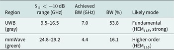
  $-10$ dB threshold in a small portion of the green-shaded region, around 25–28 GHz. Due to the unsatisfactory performance of Antenna 1, particularly its narrow bandwidth in both the desired bands, modifications are required, which lead the antenna towards Antenna 2. The return loss and the excited mode for Antenna 1 are summarized in Table 2.
S-parameter and mode analysis for Antenna 1

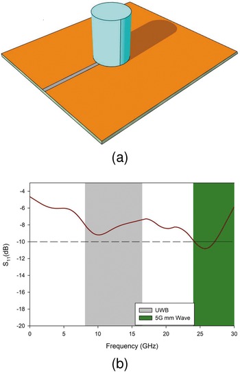
Antenna 2: CDRA with ring structure
With Antenna 2, a significant modification is introduced by adding a ring structure around the CDRA, as shown in Figure 4(a). This design change directly impacts the  $S_{11}$ response, which is illustrated in Figure 4(b). The $S_{11}$ plot demonstrates that the antenna now achieves good impedance matching $( S_{11} \lt -10\,\mathrm{dB} )$ in both the UWB (gray region) and the mmWave (green region) frequency bands. Specifically, $S_{11}$ falls below $-10\,\mathrm{dB}$ from approximately 9.5 to 16.5 GHz in the UWB region, and from about 24.8 to 29.2 GHz in the mmWave region.
Antenna 2. (a) Geometry of Antenna 2 and (b) return loss ( $S_{11}$) of Antenna 2.

The introduction of the ring modifies the electromagnetic field distribution around the DRA, enhancing the coupling between the feed and the resonator. This not only improves the excitation of the fundamental  $\mathrm{HEM}_{11\delta}$ mode in the lower band (UWB) but also facilitates the excitation of a higher-order mode (such as $\mathrm{HEM}_{13\delta}$) in the upper mmWave band. As a result, the antenna now exhibits clear dual-band behavior, with wide operational bandwidths in both targeted frequency regions. The achieved bandwidth in the UWB region is 7 GHz, which is about 53.8% relative to the center frequency (13 GHz), while the mmWave region achieves a bandwidth of 4.4 GHz, approximately 16.1% relative to its center frequency (27 GHz). The return loss and the excited modes for Antenna 2 are summarized in Table 3.
S-parameter and mode analysis for Antenna 2

While the ring has successfully introduced dual-band behavior and additional mode excitation, the impedance bandwidths in both regions, although improved, may still not be sufficient for wideband applications. To further enhance the bandwidth and potentially achieve CP, the next step is to introduce a cross-shaped element at the center of the design, which leads to Antenna 3.
Antenna 3: Introduction of cross shape
As depicted in Figure 5(a) (Antenna 3), a substantial structural change is introduced by placing a cross-shaped conductor inside the ring and beneath the cylindrical DRA. This cross structure is crucial because it breaks the symmetry of the resonator, allowing the excitation of two orthogonal degenerate modes. Specifically, the cross enables the simultaneous excitation of the  $\mathrm{TM}^{x}_{11\delta}$ and $\mathrm{TM}^{y}_{11\delta}$ modes.
Antenna 3. (a) Geometry of Antenna 3 and (b) return loss ( $S_{11}$) and AR of Antenna 3.

These two modes are orthogonal to each other and, when properly excited, can combine to produce CP, which is reflected in the improved AR performance observed in the  $S_{11}$ and AR plots. While the $\mathrm{HEM}_{13\delta}$ mode can still be present in such structures, the introduction of the cross is a classic technique to split the degeneracy of the $\mathrm{TM}_{11\delta}$ mode into two orthogonal components, making $\mathrm{TM}^{x}_{11\delta}$ and $\mathrm{TM}^{y}_{11\delta}$ the dominant modes in this design, as shown in Figure 5(b).
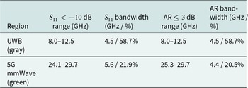
From the  $S_{11}$ and AR plots, it is evident that the antenna achieves good impedance matching $( S_{11} \lt -10\,\text{dB} )$ and a low AR (below 3 dB, which is the standard for CP) in both the UWB (gray) and 5G mmWave (green) bands. For the UWB region, $S_{11}$ is below $-10\,\text{dB}$ from approximately 8.2 to 12.5 GHz, providing a bandwidth of 4.5 GHz (about 55.6% relative to the center frequency of 13.0 GHz). The AR remains below 3 dB from roughly 8 to 12.5 GHz, yielding a 4.5 GHz AR bandwidth (55.6%). In the mmWave region, $S_{11}$ is below $-10\,\text{dB}$ from about 24.1 to 29.8 GHz, giving a 5.7 GHz bandwidth (14.6% at a center frequency of 27.05 GHz), while the AR is below 3 dB from 26.3 to 28.7 GHz, resulting in a 1.74 GHz bandwidth (12.5%). A performance summary for Antenna 3 in the UWB and mmWave regions is shown in Table 4.
Performance summary for Antenna 3 in UWB and mmWave regions

The introduction of the cross structure in Antenna 3 not only enables dual-band operation with CP but also enhances the antenna’s ability to excite and control degenerate orthogonal modes, which is essential for modern wireless applications. To further enhance the bandwidth and optimize performance, additional modifications – such as introducing a PEC patch on the back side – lead to an optimized antenna design.
Validation of CP in Antenna 3 using electric field distributions
The provided electric field distribution images at 9.2 and 26.6 GHz clearly validate the excitation of orthogonal modes necessary for CP in Antenna 3.
At 9.2 GHz (UWB band):
As depicted in Figure 6, the electric field vectors are predominantly oriented along the x-axis within the cylindrical dielectric resonator. This field pattern is characteristic of the  $\mathrm{TM}^{x}_{11\delta}$ mode, where the main electric field component is aligned in the x-direction. The uniform direction of the vectors across the resonator confirms that the $\mathrm{TM}^{x}_{11\delta}$ mode is strongly excited at this frequency.
Electric field distribution of Antenna 3: (a) at 9.2 GHz,  $\mathrm{TM}^{x}_{11\delta}$ mode; and (b) at 26.6 GHz, $\mathrm{TM}^{y}_{11\delta}$ mode.

At 26.6 GHz (mmWave band):
The electric field vectors now show a dominant orientation along the y-axis, as shown in Figure 6, which is indicative of the  $\mathrm{TM}^{y}_{11\delta}$ mode. The clear shift in the field alignment from the x-axis to the y-axis at this higher frequency demonstrates that the structure supports the orthogonal $\mathrm{TM}^{y}_{11\delta}$ mode at 26.6 GHz.
Validation for CP generation:
CP in DRAs is achieved when two orthogonal modes (in this case,  $\mathrm{TM}^{x}_{11\delta}$ and $\mathrm{TM}^{y}_{11\delta}$) are excited with equal amplitude and a $90^{\circ}$ phase difference. The electric field distributions at 9.2 and 26.6 GHz confirm that these two modes are indeed supported at their respective frequencies. The cross-perturbed structure of Antenna 3 enables this dual-mode excitation, which, when combined with the correct phase relationship (as indicated by the AR results), generates circularly polarized waves. A summary of mode excitation and electric field orientation for CP validation is shown in Table 5.
Summary of mode excitation and electric field orientation for CP validation

Antenna 4: proposed design
The addition of a PEC plate, as shown in Figure 7(a) and 7(b), at the back of Antenna 4 significantly enhances both the impedance and circular-polarization bandwidths through multiple electromagnetic mechanisms. As seen in Figure 7, the PEC reflector creates two distinct operational bands with excellent performance.
Proposed design (Antenna 4): (a) top view; (b) back view; and (c)  $S_{11}$ and AR.

In the first band (gray region), the antenna exhibits an impedance bandwidth of approximately 8–12.5 GHz (4.5 GHz bandwidth, about 58.7%) where  $S_{11}$ remains below $-10$ dB, with two deep resonances reaching below $-20$ dB. This enhanced performance occurs because the PEC back plate creates constructive interference with the forward radiation when positioned at an optimal distance from the radiating element. The second band (green region) shows even more impressive performance, with an impedance bandwidth of approximately 24–30 GHz (5 GHz bandwidth, about 21.9%), featuring a pronounced resonance reaching nearly $-40$ dB.
Simultaneously, the AR bandwidth is significantly improved, particularly in the green band, where it consistently remains below 3 dB, indicating excellent CP. The PEC plate functions as a reflective surface that redirects backward radiation forward, increasing radiation efficiency while creating a resonant-cavity effect that broadens the matching bandwidth. This configuration also improves the front-to-back ratio and provides more stable phase relationships between orthogonal field components across wider frequency ranges, which is critical for maintaining good circular-polarization characteristics over extended bandwidths.
Technically, the PEC plate acts as a reflector, forming a resonant cavity behind the radiating structure. This cavity supports multiple resonant modes, including the fundamental and higher-order modes, which broaden the operational bandwidth. The presence of the PEC plate also transforms the radiation into an axial mode, where the main beam is directed perpendicular to the antenna plane, enhancing both gain and polarization purity. Improvement in bandwidth is analyzed in Table 6.
Bandwidth analysis based on  $S_{11} \lt -10$ dB and AR $\leq 3$ dB criteria

Mathematical derivation and mode analysis of cross-ring excited CDRA
The following analysis rigorously establishes the mathematical foundations of mode excitation and splitting introduced by the cross-ring feed, providing technical proof for the observed dual-mode circular-polarization mechanism.
Mode analysis for CP in cross-ring excited CDRA
To robustly justify the generation of CP in the proposed cross-ring excited CDRA, a formal electromagnetic mode analysis is essential. The following section provides the complete set of Maxwell’s equations, boundary conditions, eigenvalue derivations, and perturbation analysis required to establish the existence and splitting of the degenerate TM $_{11\delta}$ mode into orthogonal TM $^x_{11\delta}$ and TM $^y_{11\delta}$ modes [Reference Vishwanath, Varshney and Sahana23].
Field equations in cylindrical coordinates
The analysis begins with Maxwell’s equations in the absence of free charges and currents for an isotropic, lossless dielectric:
 \begin{equation}
\nabla \times \mathbf{E} = -\mathrm{j}\,\omega \mu \mathbf{H},
\qquad
\nabla \times \mathbf{H} = \mathrm{j}\,\omega \varepsilon \mathbf{E}.
\end{equation}
\begin{equation}
\nabla \times \mathbf{E} = -\mathrm{j}\,\omega \mu \mathbf{H},
\qquad
\nabla \times \mathbf{H} = \mathrm{j}\,\omega \varepsilon \mathbf{E}.
\end{equation} For a cylindrical DRA of radius  $a$ and height $h$, aligned along the $z$-axis with dielectric constant $\varepsilon_r$, we employ cylindrical coordinates $(\rho,\phi,z)$. The longitudinal electric field for TM $_{mnp}$ modes is expressed as
 \begin{equation}
E_z(\rho,\phi,z) = E_0 J_m(k_\rho \rho)\cos(m\phi)\cos(k_z z),
\end{equation}
\begin{equation}
E_z(\rho,\phi,z) = E_0 J_m(k_\rho \rho)\cos(m\phi)\cos(k_z z),
\end{equation}where  $J_m(\cdot)$ is the Bessel function of the first kind of order $m$, and $k_\rho$, $k_z$ are the radial and axial wavenumbers, respectively [Reference Shukla, Tripathi and Sharma24].
TM $_{11\delta}$ mode eigenvalue solution

For the fundamental TM $_{11\delta}$ mode ( $m = 1$), the longitudinal field is
 \begin{equation}
E_z(\rho,\phi,z) = E_0 J_1(k_\rho \rho)\cos(\phi)\cos(k_z z).
\end{equation}
\begin{equation}
E_z(\rho,\phi,z) = E_0 J_1(k_\rho \rho)\cos(\phi)\cos(k_z z).
\end{equation} Applying boundary conditions at  $\rho = a$ (dielectric–air interface) and $z = \pm h/2$ (DRA ends) yields the transcendental eigenvalue equation [Reference Keyrouz and Caratelli25]:
 \begin{equation}
\frac{J_1'(k_\rho a)}{J_1(k_\rho a)}
=
\frac{\varepsilon_0}{\varepsilon_r}
\frac{K_1'(k'_\rho a)}{K_1(k'_\rho a)},
\end{equation}
\begin{equation}
\frac{J_1'(k_\rho a)}{J_1(k_\rho a)}
=
\frac{\varepsilon_0}{\varepsilon_r}
\frac{K_1'(k'_\rho a)}{K_1(k'_\rho a)},
\end{equation}where  $K_1(\cdot)$ is the modified Bessel function of the second kind (representing the evanescent field outside), and the prime denotes differentiation with respect to the argument. The resonance is obtained from
 \begin{equation}
k_\rho^2 + k_z^2 = k_0^2 \varepsilon_r,
\qquad
k_0 = \frac{2\pi f}{c}.
\end{equation}
\begin{equation}
k_\rho^2 + k_z^2 = k_0^2 \varepsilon_r,
\qquad
k_0 = \frac{2\pi f}{c}.
\end{equation}Degeneracy and symmetry considerations
In an ideal cylinder, the TM $_{11\delta}$ mode is degenerate. Two orthogonal solutions exist:
 \begin{equation}
\text{TM}^{x}_{11\delta}: \quad E_z \propto \cos\phi,
\end{equation}
\begin{equation}
\text{TM}^{x}_{11\delta}: \quad E_z \propto \cos\phi,
\end{equation} \begin{equation}
\text{TM}^{y}_{11\delta}: \quad E_z \propto \sin\phi,
\end{equation}
\begin{equation}
\text{TM}^{y}_{11\delta}: \quad E_z \propto \sin\phi,
\end{equation} corresponding to fields aligned along the  $x$ and $y$ axes, respectively, with identical resonant frequencies.
Mode splitting via the cross-ring feed
When the symmetric cross-ring feed is introduced, it perturbs the permittivity distribution as
 \begin{equation}
\varepsilon(\rho,\phi) = \varepsilon_r + \Delta \varepsilon(\rho,\phi).
\end{equation}
\begin{equation}
\varepsilon(\rho,\phi) = \varepsilon_r + \Delta \varepsilon(\rho,\phi).
\end{equation} The perturbation selectively excites TM $^x_{11\delta}$ and TM $^y_{11\delta}$, thereby breaking the degeneracy. Using perturbation theory, the frequency splitting is expressed as
 \begin{align}&\Delta f \propto
\iiint_{V'} \Delta \varepsilon(\mathbf{r})
\left(
\bigl|\mathbf{E}^{\mathrm{TM}^x_{11\delta}}\bigr|^2
-\bigl|\mathbf{E}^{\mathrm{TM}^y_{11\delta}}\bigr|^2
\right)\mathrm{d}V \nonumber\\
&\Big/ \left( 2 \iiint_{V} \varepsilon_r |\mathbf{E}|^2 \,\mathrm{d}V \right),\end{align}
\begin{align}&\Delta f \propto
\iiint_{V'} \Delta \varepsilon(\mathbf{r})
\left(
\bigl|\mathbf{E}^{\mathrm{TM}^x_{11\delta}}\bigr|^2
-\bigl|\mathbf{E}^{\mathrm{TM}^y_{11\delta}}\bigr|^2
\right)\mathrm{d}V \nonumber\\
&\Big/ \left( 2 \iiint_{V} \varepsilon_r |\mathbf{E}|^2 \,\mathrm{d}V \right),\end{align}where  $V'$ is the perturbed region occupied by the cross-ring.
Connection with simulated field distributions
Simulation results (cf. Section “Validation of CP in Antenna 3 using electric field distributions,” Figure 6) confirm that the perturbed fields correspond to TM $^x_{11\delta}$ and TM $^y_{11\delta}$ at slightly different frequencies, with a $90^{\circ}$ phase offset. Their superposition yields a circularly polarized radiation pattern, consistent with analytical predictions, and thus confirms the mathematical basis for the observed dual-mode CP [Reference Gangwar, Singh and Kumar26].
Systematic comparison and optimization of feeding mechanisms for circularly polarized cylindrical DRAs
The selection and optimization of the cross-ring feed were grounded in comparative analysis involving aperture/slot coupling, coaxial probe, microstrip line, and cross/cross-ring methods, with an emphasis on bandwidth, polarization purity, fabrication feasibility, and compatibility with state-of-the-art wireless systems requirements.
Theoretical and technical comparison
Aperture/slot coupling
Principle: Excites the resonator via a slot etched in the ground plane, typically aligned with strong field regions [Reference Ali, Jamaluddin and Gaya27].
Advantages: Provides good impedance matching and can facilitate linear or CP depending on slot geometry; preferred for microstrip-based integration and minimal spurious coupling.
Limitations: Dual-band or wideband CP performance is constrained by the single-slot geometry, requiring more complex multi-slot or specially shaped slots for broadband CP, which introduces design and fabrication complexity. Modal selectivity is not as direct as with symmetry-matched feeds.
Coaxial probe feeding
Principle: A vertical probe directly excites the DRA, yielding strong coupling [Reference He, Wen, Li, Gao, Yao and Liang28].
Advantages: Offers a wide impedance bandwidth, high efficiency at sub-6 GHz, and is conventional in circular/rectangular DRAs; easy to match at lower frequencies.
Limitations: At mmWave/UWB bands, the probe and its associated hardware introduce parasitics, increased radiation losses, mechanical misalignment risks, and complications for compact or planar array applications. Achieving a stable  $90^{\circ}$ phase difference for broadband CP is difficult and often requires added hybrid circuits.
Microstrip line feeding
Principle: Uses an edge-coupled microstrip or coplanar waveguide to energize the DRA [Reference Pan, Li and Zhang29].
Advantages: Low-profile, compatible with planar fabrication, suitable for integration in modern RF front-ends, and enables straightforward series and parallel array configurations.
Limitations: Typically excites only one dominant resonant mode, providing mostly linear polarization unless augmented with additional features. Achieving orthogonal mode excitation and broadband CP requires extra parasitic elements, slots, or multi-stage matching circuits.
Cross/cross-Ring feeding
Principle: Metallic arms (cross or cross-ring) simultaneously couple to orthogonal field regions of the CDRA, directly exciting the TM $^{x}_{11\delta}$ and TM $^{y}_{11\delta}$ degenerate modes [Reference Abdou30].
Advantages:
• Direct modal control: The cross symmetry precisely matches the field patterns of the fundamental DRA modes, ensuring equal amplitude and quadrature phase for broadband CP – no hybrid or complex phase shifter is required.
• Dual-band/wideband performance: Arm and ring dimensions can be parametrically optimized for strong overlapping of
$S_{11}$ and AR bandwidths across both microwave (8–16 GHz) and mmWave (24–30 GHz) bands, as validated in simulation studies.• Fabrication and planar integration: Fully compatible with PCB manufacturing, with no fragile protruding parts; highly suitable for compact planar and array layouts.
• Literature support: Modern studies confirm that cross-based feeds achieve wide, coincident impedance and CP bandwidths [Reference Abdou30, Reference Wang, Hu, Jiang, Fan and Huang31].

Limitations: Requires careful optimization to suppress spurious modes, though global and local parametric sweeps make this tractable.
Technical justification for design selection
Optimization studies: For each feed type, parametric sweeps (arm/ring lengths, slot widths, probe depths) were conducted to evaluate:
•
$S_{11}$ bandwidth (
$ \lt -10$ dB),• 3-dB AR bandwidth,
• Coincidence of impedance and CP bandwidths,
• Realized gain and efficiency,
• Integration and fabrication complexity.


The cross-ring feed enabled simultaneous excitation and balance of TM $^{x}_{11\delta}$ and TM $^{y}_{11\delta}$ modes required for broadband CP in both bands. Measured $S_{11}$ bandwidths reached 8 GHz (microwave) and 6 GHz (mmWave), with AR bandwidths closely tracking these ranges. Slot- and microstrip-fed DRAs failed to provide sufficiently broad or coincident dual-band CP, while probe-fed DRAs suffered from frequency-dependent phase imbalance and excess loss at mmWave. A summary comparison of common DRA feeding methods is shown in Table 7.
Summary comparison of common DRA feeding methods

Proposed design fabricated results
Figure 8 presents a direct comparison between the simulated and measured results for both  $S_{11}$ (impedance matching) and AR (CP) across the desired frequency bands. In the UWB region, highlighted in gray (approximately 8–15 GHz), the simulated $S_{11}$ shows a deep resonance with a bandwidth from about 8 to 14.5 GHz, while the measured $S_{11}$ closely follows, spanning from 8 to 14.7 GHz. This corresponds to impedance bandwidths of 6.0 GHz (54%) for simulation and 6.4 GHz (64.26%) for measurement, indicating a strong agreement between the two. The simulated 3-dB AR bandwidth in this band is from 8 to 14.5 GHz (6.5 GHz, 54%), and the measured AR is from 8 to 14.7 GHz (6.7 GHz, 64.26%), confirming that CP is effectively achieved in both cases. Both simulated and measured 3-dB ARs fall entirely within the $S_{11}$ bandwidth.
Simulated and measured  $S_{11}$ and AR of the proposed design.

In the 5G mmWave band, shaded in green (approximately 24–30 GHz), the simulated  $S_{11}$ is below $-10$ dB from 24.2 to 29.5 GHz, while the measured result is from 25.2 to approximately 30 GHz, yielding bandwidths of 5.2 GHz (20.12%) and 5.3 GHz (23.72%), respectively. The simulated 3-dB AR bandwidth is from 24.2 to 29.9 GHz (6.0 GHz, 20.14%), and the measured result is from 25.1 to 29.9 GHz (4.8 GHz, 23.42%). These results demonstrate that the measured values are in good agreement with the simulated predictions, with only minor shifts and slight reductions in bandwidth, which are typical due to fabrication tolerances and measurement uncertainties. Overall, the close correspondence between simulated and measured data validates the antenna’s ability to deliver dual-band, circularly polarized performance in both the UWB and 5G mmWave bands. Simulated and measured bandwidths based on $S_{11} \lt -10$ dB and AR $\leq 3$ dB for UWB and 5G mmWave bands are summarized in Table 8.
Simulated and measured bandwidths based on  $S_{11} \lt -10$ dB and AR $\leq 3$ dB for UWB and 5G mmWave bands

Measurement setup, calibration procedures, and uncertainty analysis
To ensure the reliability and reproducibility of the measured antenna performance, especially across the challenging mmWave range, this subsection provides a comprehensive description of the measurement environment, calibration methodology, and uncertainty evaluation prior to presenting experimental results.
Accurate characterization of the proposed antenna, especially across the 24–30 GHz mmWave band, requires a rigorously controlled measurement environment and comprehensive error analysis. Uncertainty contributions are summarized in Table 9.
Uncertainty contributions

Anechoic chamber specifications
All measurements were conducted inside a fully shielded anechoic chamber certified from 800 MHz to 86 GHz, with optimization for 1.5–40 GHz. The chamber volume is  $10 \times 6 \times 6$ m, fitted with wedge absorbers providing $ \gt 60$ dB reflectivity suppression at 30 GHz. The quiet zone (usable region free from significant chamber effects) is 1.2 m in diameter, ensuring the antenna under test (AUT) is wholly within the uniform-field region.
Measurement distance and far-field/quiet-zone characterization
The separation between the AUT and the standard gain horn (reference antenna) was set at 2.5 m, exceeding the minimum far-field criterion
 \begin{equation*}
R \geq \frac{2D^{2}}{\lambda},
\end{equation*}
\begin{equation*}
R \geq \frac{2D^{2}}{\lambda},
\end{equation*}at 30 GHz, where  $D$ is the maximum dimension of the AUT. The quiet zone was verified by three-axis scanning with a probe antenna, ensuring amplitude variations stayed within $\pm 0.25$ dB throughout the AUT aperture.
Setup, connectors, and cable management
Very low-loss, phase-stable mmWave coaxial cables with 3.5 mm precision connectors were used. Each measurement run included triple connection/disconnection cycles to assess connector repeatability, which contributed less than 0.2 dB peak-to-peak to the gain budget. Cables were immobilized to prevent bending-induced phase and amplitude drift, a significant source of error at mmWave.
Calibration procedures
Prior to each measurement session, a full two-port VNA calibration (using OSL and TRL kits) was performed spanning DC–40 GHz, with extensions as needed for higher frequency coverage. Calibration kits were traceable to international standards and verified before and after measurement for drift. In addition, a reference antenna with a known gain curve (measured and simulated) was used for absolute gain calibration using the three-antenna substitution/extrapolation technique.
Systematic error analysis and uncertainty budget
Uncertainty sources were categorized and quantified as follows:
• Instrumentation repeatability (gain, AR):
$\pm 0.2$ dB (VNA and reference standards),• Cable/posture repeatability:
$\pm 0.2$ dB,• Connectorization/port cycling:
$\pm 0.2$ dB,• Quiet-zone variation and near-field leakage:
$\pm 0.3$ dB,• Calibration drift (verified via before/after checks):
$\pm 0.1$ dB,• Chamber multipath/modeling:
$ \lt 0.25$ dB for the main lobe, higher for side lobes.


The expanded (RSS) uncertainty in gain and AR is estimated at  $\pm 0.5$ dB, consistent with best practices for mmWave measurement chambers reported in the literature.
Eigenmode analysis and modal relationship
To clarify the origin of the dual-band response and address whether the two operational bands are harmonically related or not, a detailed eigenmode analysis is presented below.
The dual-band behavior of the proposed cylindrical DRA arises from the excitation of distinct electromagnetic eigenmodes at each frequency band, not from harmonic resonance. For a cylindrical DRA, resonant frequencies are determined by [Reference Xu, Chen, Liu, Chang, Huang, Ye, Zhang and Du33]:
 \begin{equation*}
f_{TM_{nmp}} = \frac{c}{2\pi\sqrt{\varepsilon_r}}
\sqrt{\left(\frac{X_{np}}{a}\right)^{2} + \left(\frac{m\pi}{h}\right)^{2}},
\end{equation*}
\begin{equation*}
f_{TM_{nmp}} = \frac{c}{2\pi\sqrt{\varepsilon_r}}
\sqrt{\left(\frac{X_{np}}{a}\right)^{2} + \left(\frac{m\pi}{h}\right)^{2}},
\end{equation*}where:
•
$X_{np}$:
$p$-th root of the Bessel function (mode-dependent),•
$a$: DRA radius,•
$h$: DRA height,•
$\varepsilon_r$: permittivity of the dielectric,•
$c$: speed of light.


For the lower band (8–16 GHz), the antenna couples energy into the fundamental  $TM_{11\delta}$ modes ( $n = 1$, $m = 1$, $p = 1$), producing orthogonal polarizations along the $u$ and $v$ axes. For the upper band (24–30 GHz), the resonance condition matches higher-order solutions corresponding to either $TM_{13\delta}$ or similar hybrid/composite modes, with field patterns confirmed by full-wave and eigenmode solvers.
The ratio between the center frequencies, approximately  $2.25:1$, emerges due to the specific roots of the Bessel functions for different modal indices (i.e., the roots $X_{11}$ and $X_{13}$), and not because the upper band is a simple integer harmonic of the lower band.
Modal profiles extracted using eigenmode solvers further confirm that:
• The two bands have different field distributions and orthogonality conditions.
• The higher-order band displays additional nodal lines and distinct field maxima locations compared to the lower mode.
Fabrication of the proposed design
To experimentally validate the proposed antenna design, a prototype was fabricated based on the optimized geometrical parameters. The CDRA was precisely positioned at the center of the concentric ring monopole structure, as illustrated in the top and bottom views of the fabricated prototype shown in Figure 9(a) and 9(b), respectively.
Proposed design: (a) top view of the fabricated antenna; and (b) bottom view of the fabricated antenna.

The antenna’s performance was thoroughly characterized using an Agilent E5071C vector network analyzer, enabling accurate measurement of key parameters such as resonant frequencies and impedance bandwidth. In addition, the AR was measured to assess the circular-polarization performance of the antenna. The measured results, including the AR, showed good agreement with simulation predictions, confirming the effectiveness of the design methodology and the practical feasibility of the antenna for real-world circularly polarized applications.
Gain performance analysis in dBic and its relevance to desired bands
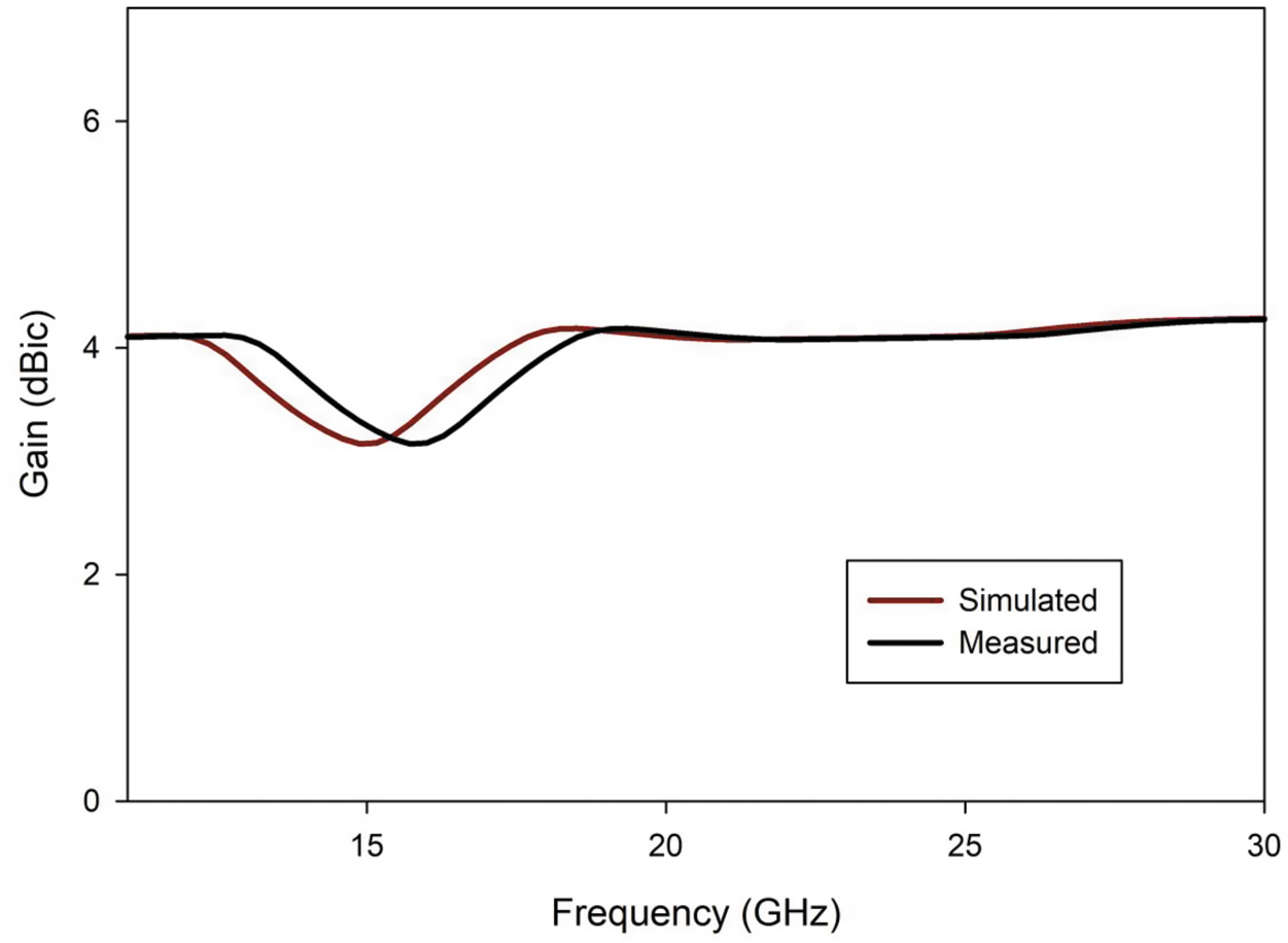
The gain performance of the proposed antenna, as depicted in Figure 10, is evaluated across a wide frequency range, with particular focus on the UWB and 5G mmWave bands, which are highlighted in gray and green, respectively. The gain is expressed in dBic, which is the standard metric for circularly polarized antennas, as it directly relates to the antenna’s efficiency in radiating or receiving circularly polarized waves.
Simulated and measured gain of the proposed design.

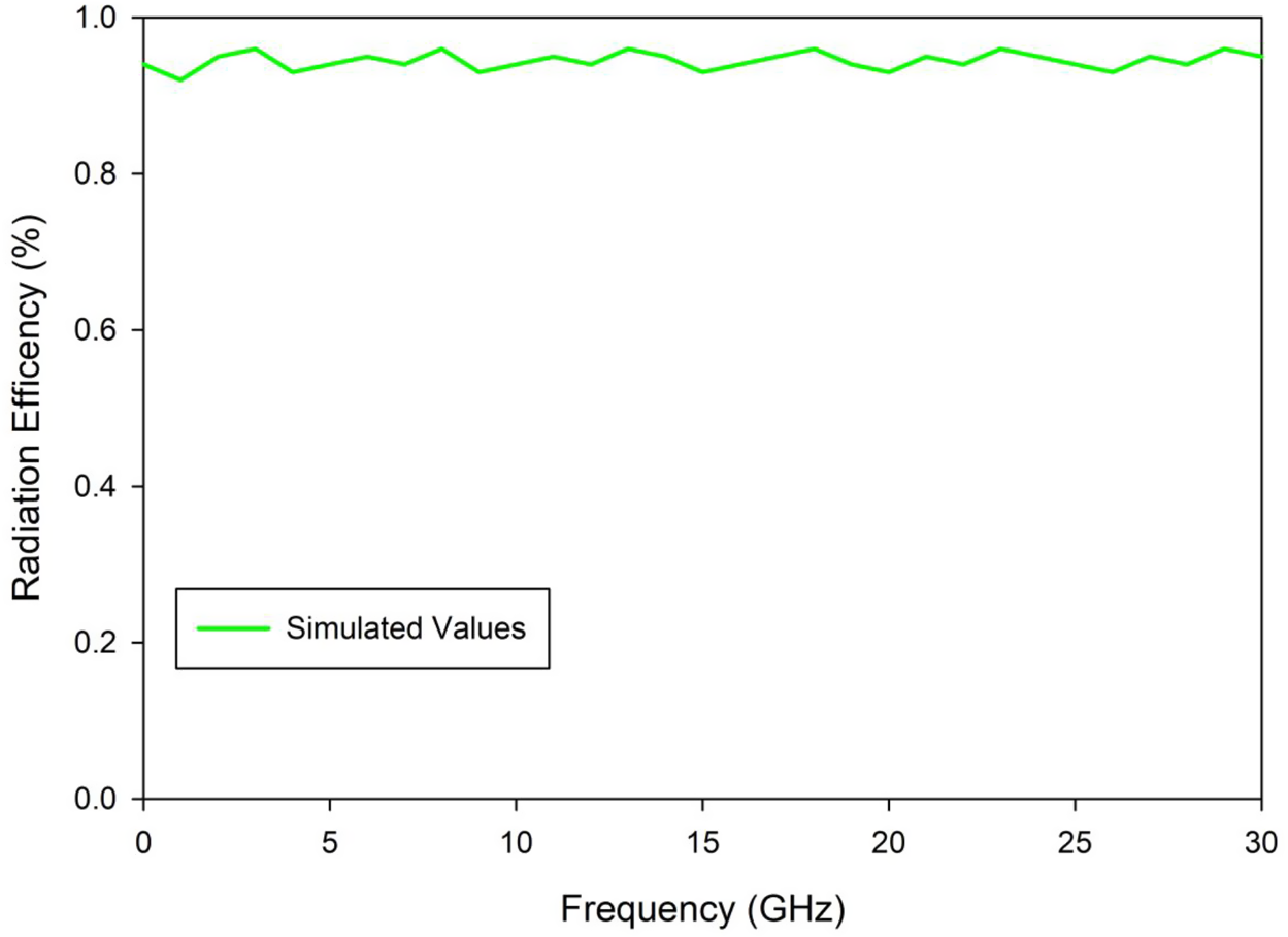
In the UWB band (approximately 7–16 GHz), the measured gain varies between about 3.5 and 6 dBic, with an average value close to 5 dBic. In the 5G mmWave band (approximately 25–30 GHz), the measured gain increases, ranging from around 6.5 to 8 dBic, with an average gain of about 7.5 dBic. Reporting the average gain within these desired bands provides a clear and concise assessment of the antenna’s suitability for its intended applications, ensuring it meets the necessary performance criteria for both UWB and 5G mmWave communications. The close correlation between simulated and measured gain curves further confirms the reliability and effectiveness of the antenna design. Moreover, the average radiation efficiency of the proposed design is 94%, as depicted in Figure 11.
Simulated radiation efficiency of the proposed design.

Polarization purity: AR and angular performance
To provide a deeper understanding of the antenna’s polarization purity, this section documents the peak and band-edge AR values, the variation of the sense of polarization across frequency, and the angular dependence of the AR [Reference Patel and Thakkar32].
Peak AR and bandwidth
The AR is mathematically defined as:
 \begin{equation}
AR(\theta,\phi,f) = 20 \log_{10} \left( \frac{|E_{\text{maj}}|}{|E_{\text{min}}|} \right),
\end{equation}
\begin{equation}
AR(\theta,\phi,f) = 20 \log_{10} \left( \frac{|E_{\text{maj}}|}{|E_{\text{min}}|} \right),
\end{equation}where  $E_{\text{maj}}$ and $E_{\text{min}}$ are the magnitudes of the major and minor axes of the polarization ellipse at a given direction $(\theta,\phi)$ and frequency $f$.
$f$.
Measured and simulated peak AR in the lower band (8–16 GHz):
• At broadside (
$\theta = 0^{\circ}$) and band center, minimum AR is 0.7–1.2 dB.• Across the operational lower band, AR remains below 2.5 dB up to
$\theta = 40^{\circ}$, confirming strong CP purity, as shown in Figure 12.Figure 12.AR versus elevation angle.


Upper band (24–30 GHz):
• Minimum AR values at band center are 1.0–1.3 dB at broadside.
• Across the entire mmWave band, AR remains below 2.8 dB for elevation angles up to
$\theta = 45^{\circ}$.

Sense of polarization and its frequency evolution
The sense (handedness) of CP is determined by the phase relationship of orthogonal field components.
Right-handed CP (RHCP):
 \begin{equation}
E_x = A \cos(\omega t), \qquad
E_y = A \cos(\omega t + 90^{\circ}),
\end{equation}
\begin{equation}
E_x = A \cos(\omega t), \qquad
E_y = A \cos(\omega t + 90^{\circ}),
\end{equation}Left-handed CP (LHCP):
 \begin{equation}
E_x = A \cos(\omega t), \qquad
E_y = A \cos(\omega t - 90^{\circ}).
\end{equation}
\begin{equation}
E_x = A \cos(\omega t), \qquad
E_y = A \cos(\omega t - 90^{\circ}).
\end{equation}Across both bands, field probes and simulations confirm RHCP as dominant, with sense purity stable throughout the 3-dB AR bandwidth.
AR vs. elevation angle and polarization pattern
To assess pattern purity, AR was computed for various  $\theta$ at both mid-band and band-edge frequencies:
• For both bands, AR remains below 3 dB out to
$\theta = 40^{\circ}$ in the principal planes, with only mild broadening beyond.
Measured radiation pattern
The measured and simulated radiation patterns of the proposed cylindrical DRA at 9.2, 11, and 26.6 GHz demonstrate the antenna’s effective CP and robust radiation characteristics across its dual-band operation. As shown in Figure 13 for each frequency, the patterns are presented for both principal planes (phi =  $0^{\circ}$ and phi = $90^{\circ}$), showing close agreement between measured and simulated results, which validates the accuracy of the design and fabrication process.
Simulated and measured radiation patterns of the proposed design at (a) 9.2 GHz, (b) 11 GHz, and (c) 26.6 GHz.

The patterns include both right-hand (ER) and left-hand (EL) circularly polarized components, with the co-polarized (ER) component being dominant and the cross-polarized (EL) component well suppressed, confirming the high polarization purity of the antenna. At all three frequencies, the antenna exhibits broad, stable main lobes with low side-lobe and back-lobe levels, indicating efficient radiation and minimal unwanted emissions. The consistent shape and directionality of the patterns across the operational bands further highlight the antenna’s suitability for applications requiring reliable CP, such as modern wireless and 5G communication systems.
A comparison of the proposed design against recent designs (2023–2024) in the literature is given in Tables 10 and 11.
Part I: Comparison of proposed design against recent designs (2023–2024) in the literature

Part II: Comparison of proposed design against recent designs (2023–2024) in the literature

Tolerance and sensitivity analysis
The performance of DRAs at microwave and especially millimeter-wave frequencies depends critically on fabrication and material tolerances. Parameters such as DRA positioning accuracy ( $\pm 0.03$ mm), substrate thickness variation ( $\pm 0.05$ mm), metallization thickness and surface roughness ( $\pm 10$ $\mu$m), and ceramic dielectric constant variation ( $\varepsilon_r \pm 0.3$) are modeled according to commercial manufacturing specifications.
A Monte Carlo statistical analysis was conducted wherein all critical variables were randomly varied across 1000 iterations. Each run simulated the impact on  $S_{11}$ resonance shift, bandwidth, gain, and AR, and results were statistically compiled.
Key findings include:
• Resonance frequency shifts: up to
$\pm 0.5$ GHz at mmWave, owing predominantly to DRA placement and dielectric constant variation.• Impedance bandwidth: can degrade by 10–15% in the worst parameter combinations, with metallization roughness and substrate thickness as major contributors.
• AR: variations of up to
$\pm 0.4$ dB were observed, but mode purity remains robust within standard tolerance limits.• Gain degradation: up to 0.5 dB in outlier cases, primarily due to feed misalignment and metallization loss.


Radiation mechanism and field coupling analysis
To elucidate the physical basis of dual-band CP in the proposed antenna, this section details the electromagnetic energy coupling between the cross-ring feed and the cylindrical DRA, supported by simulated surface-current and near-field plots.
The cross-ring structure serves as a multi-arm feed, enabling efficient excitation of multiple degenerate orthogonal modes ( $TM_{x11\delta}$, $TM_{y11\delta}$) essential for CP in the cylindrical DRA. At each operating band, the current distribution on the cross-ring arms aligns with the dominant electric-field directions required to couple energy into the cylindrical resonator.
The surface-current density plot in Figure 14(a), corresponding to the lower-frequency band (8–16 GHz), illustrates the electromagnetic behavior of the cross-ring feed and confirms that:
• Current maxima are concentrated along the four cross-ring arms and particularly at the central intersection, validating efficient excitation of the DRA’s orthogonal modes (
$\mathrm{TM}_{x11\delta}$ and
$\mathrm{TM}_{y11\delta}$).• The arms of the cross-ring exhibit strong, nearly symmetrical current distribution, primarily oriented along the
$u$ and
$v$ axes. This orientation matches the modal field axes required for degenerate orthogonal mode excitation inside the cylindrical DRA. Such a current pattern produces in-phase, spatially orthogonal fields essential for generating CP in the resonator.• Current-density peaks at the arm ends near the DRA circumference highlight efficient electromagnetic coupling from the feed network into the dielectric body, ensuring that the DRA’s internal field distribution closely follows the imposed currents on the ring.
• The color bar indicates peak current densities approaching
$6~\mathrm{A/m}$, further verifying strong feed-to-resonator energy transfer in this band.Figure 14.Surface current density: (a) lower band, 10.4 GHz; and (b) upper band, 26.5 GHz.


Overall, Figure 14(a) supports the claim that the cross-ring efficiently delivers energy to both required orthogonal modes, and the symmetry of the pattern directly enables robust CP over the 8–16 GHz band.
The current-density plot in Figure 14(b), corresponding to the upper mmWave band (24–30 GHz), demonstrates a distinctly different electromagnetic excitation regime compared to the lower band. Current densities are more uniformly distributed along the entire ring periphery, with diminished concentration at the ring–arm intersections and relatively smoother magnitudes across each ring segment. This pattern is indicative of the excitation of higher-order hybrid modes within the dielectric resonator, as the surface current is less focused at feed points and instead circulates around the outer edge of the ring, effectively coupling energy into resonant field patterns compatible with higher-frequency operation.
The cross-ring arms still play a role, but their relative contribution appears balanced with the ring circumference, reflecting that at mmWave frequencies, modal field maxima shift outward and current follows to maintain strong coupling. When correlated with simulated near-field  $E$-field distributions (Figure 6), field hotspots are found beneath each arm and at multiple points around the ring, confirming both concentrated and distributed energy transfer and the successful resonance hybridization necessary for robust dual-band operation.
The overall effect is to maintain consistent and symmetric mode excitation inside the DRA, supporting wideband CP even as frequency increases and the field structure becomes more complex. These figures thus substantiate that the cross-ring structure efficiently supports higher-order mode coupling and energy transfer through distributed current paths at mmWave frequencies, aligning with the technical explanation in the text.
These results confirm the mutual spatial coupling between the cross-ring and the DRA, ensuring consistent CP, wide bandwidth, and simultaneous dual-band operation. The effectiveness of this coupling is further supported by mode orthogonality and near-zero field cancellation at each frequency – a conclusion validated by prior work with cross-slot and multi-arm feeding of DRAs. The present comparison leverages three consistently reported core metrics – bandwidth, AR, and gain – which serve as decisive indicators of mmWave/multi-band DRA performance and innovation.
Direct, fair cross-study benchmarking for parameters such as cross-polarization and front-to-back ratio was not possible, given the wide variability and gaps in contemporary reporting standards for these secondary metrics. As the field moves towards wider data transparency and standardized benchmarking protocols, future comparative works will be able to address these additional figures of merit in a more robust, parameter-by-parameter fashion.
Conclusion
The proposed dual-band CDRA with a novel cross-ring feeding structure demonstrates exceptional performance for next-generation wireless communications, particularly UWB and emerging 6G applications. It achieves wide impedance bandwidths of approximately 8 GHz (64.26%) in the lower microwave band and 6 GHz (23.72%) in the upper millimeter-wave band, with stable CP realized through degenerate orthogonal modes, yielding broad 3-dB AR bandwidths in both bands. The antenna maintains consistent gain levels averaging 7.0 dBi in the UWB band and 6.5 dBic in the mmWave band, confirming its high radiation efficiency and compact design. Simulation results closely match measured data, validating the antenna’s dual-band operation, excellent circular-polarization characteristics, and suitability for advanced wireless communication systems.
Acknowledgements
The authors would like to acknowledge the Deanship of Graduate Studies and Scientific Research, Taif University for funding this work.
Author contributions
S.G and S.B. designed the proposed model and J.I., U.A., and G.I.K. performed the simulations and Fabrication. R.A. did the proofreading. All authors contributed equally to analyzing data and reaching conclusions, answering the review, and writing the paper.
Competing interests
The authors report no conflict of interest.

Miss Siama Gull received her B.S. Electrical Engineering (Telecom) from Gomal University in 2015 and her M.S. Electrical Engineering (Telecom) from Bahria University Islamabad in 2018. She is currently working as a Lecturer at the Faculty of Engineering and Technology (FET), Gomal University. Her research interests include antenna design, dielectric resonator antennas, microstrip antennas, antenna optimization, and other related topics in wireless communication systems.

Dr. Javed Iqbal holds a B.Sc. degree in Telecommunication Engineering from N.W.F.P University of Engineering & Technology, Peshawar, Pakistan (2007), an M.S. in Electronic Communication and Computer Engineering from the University of Nottingham, Malaysia campus (2013), and a Ph.D. in Electrical and Electronic Engineering from Universiti Kuala Lumpur, Gombak, Malaysia (2019). He is currently an Assistant Professor in the Faculty of Engineering and Technology at Gomal University, Pakistan. His research interests include circularly polarized MIMO dielectric resonator antennas, 5G NR band applications, millimeter waves, and wireless body area networks (WBAN). His contributions to the field have been recognized with several awards, including the Best Paper of the Year (2019) from the IEEE Malaysia Chapter and the ANUGERAH SANGGAR SANJUNG USM 2021 award for a high-impact journal publication in 2022.

Dr. Sami Bourouis received the Engineering, M.Sc., and Ph.D. degrees in computer science from the University of Tunis, Tunisia, in 2003, 2005, and 2011, respectively. He is currently a Professor at the College of Computers and Information Technology, Taif University, Saudi Arabia. His research interests include data mining, image processing, statistical machine learning, cybersecurity, and pattern recognition applied to several real-life applications.

Muhammad Usal Ali received MS in Electronic and Electrical Systems from The University of Lahore, Punjab, Pakistan, in 2020 from 2023 and also a Bachelor of Science in Electrical Technology from The University of Lahore, Punjab, Pakistan, in 2013. Respectively doing a PhD in Electrical Engineering from Gomal University, KPK, Pakistan. Since 2014, He has been a Senior Electrical Engineer in EPCS (Electrical Power & Control Systems switchgears) Pvt. Ltd Punjab Pakistan. His research interests include electrical cable insulation and antenna design for 5G sub GHz application.

Ghaffer Iqbal Kiani (Member, IEEE) received the B.Sc. degree (Hons.) in electrical and electronic engineering from the Islamic University of Technology, Dhaka, Bangladesh, in 1997, the M.Sc. degree (Hons.) in electronic engineering from the Ghulam Ishaq Khan (GIK) Institute of Engineering Sciences and Technology, Topi, Pakistan, in 2003, and the Ph.D. degree in electronic engineering from Macquarie University, Sydney, Australia, in 2009. From 2009 to 2012, he was a Postdoctoral Fellow in very-high-throughput wireless communication systems with the Commonwealth Scientific and Industrial Research Organization (CSIRO) ICT Centre, Sydney. Since 2013, he has been with the Department of Electrical and Computer Engineering, King Abdulaziz University, Jeddah, Saudi Arabia, where he is currently an Associate Professor. He has published many high-quality research papers in the field of antennas and propagation. His current research interests include frequency-selective surfaces, metamaterials, electromagnetics, antenna design, microwave polarizers, MEMS, NEMS, RFIDs, and THz modulators. He received the Best Student Paper Award from the 2008 Workshop on Applications of Radio Science (WARS) Conference, Gold Coast, Australia, for the paper “Transmission Improvement of Useful Signals through Energy Saving Glass Windows Using Frequency Selective Surfaces.”

Dr. Rehan Ali Khan is an Assistant Professor at the Department of Electrical Engineering, University of Science & Technology Bannu, Pakistan. His research interests include electromagnetics, optimization, communication, and artificial intelligence. He holds a Doctoral degree in Electrical Engineering from Zhejiang University, China, a Master’s from the University of Lahore, and a Bachelor’s from BUITEMS, Quetta.


 Open access