


1. Introduction
Richtmyer–Meshkov instability (RMI) occurs when a perturbed interface is accelerated by an incident shock wave (Brouillette Reference Brouillette2002). The vorticity deposited by the incident shock wave leads to the growth of the mixing region, which can be divided into different stages, e.g. linear, nonlinear, and eventual turbulent mixing. The RMI is ubiquitous in many engineering applications (Ding et al. Reference Ding, Si, Yang, Lu, Zhai and Luo2017; Grinstein, Gowardhan & Ristorcelli Reference Grinstein, Gowardhan and Ristorcelli2017; Wang et al. Reference Wang2017; Zhou et al. Reference Zhou, Clark, Clark, Glendinning, Skinner, Huntington, Hurricane, Dimits and Remington2019, Reference Zhou2021; Liang & Luo Reference Liang and Luo2023; Liu, Zhang & Xiao Reference Liu, Zhang and Xiao2023; Yuan et al. Reference Yuan, Zhao, Liu, Wang, Liu and Lu2023; Zhou Reference Zhou2024; Zhou, Sadler & Hurricane Reference Zhou, Sadler and Hurricane2025), such as inertial confinement fusion (ICF), combustion engines, underwater explosions, supernovas, molecular clouds, stellar interiors and geological flows.
In ICF experiments, interfaces separating deuterium-tritium (DT) fuel and an outer plastic ablator are subjected to RMI due to shocks induced by high-energy lasers, and a reshock as the former shocks converge and reflect at the shell centre (Leinov et al. Reference Leinov, Malamud, Elbaz, Levin, Ben-Dor, Shvarts and Sadot2009; Weber et al. Reference Weber, Clark, Cook, Busby and Robey2014; Li et al. Reference Li, Yan, Zhao, Zheng, Zhang and Lu2022; Fu et al. Reference Fu, Zhang, Cai, Yao and Zhu2023; Liu et al. Reference Liu, Zhang, Xin, Pu, Li, Tao, Sun, Yan and Zheng2024). The reshock interacts with the developing perturbed interface and dramatically enhances mixing (Zhou Reference Zhou2017b; Bender et al. Reference Bender2021). The rapid development of RMI induces the outer ablative material into the inner DT and decreases the temperature and density that are critical for self-sustaining thermonuclear burn.
In the past few decades, many critical experimental studies have considered multiple shock waves (Vetter & Sturtevant Reference Vetter and Sturtevant1995; Balakumar et al. Reference Balakumar, Orlicz, Tomkins and Prestridge2008, Reference Balakumar, Orlicz, Ristorcelli, Balasubramanian, Prestridge and Tomkins2012; Leinov et al. Reference Leinov, Sadot, Formoza, Malamud, Elbaz, Levin, Ben-Dor and Shvarts2008, Reference Leinov, Malamud, Elbaz, Levin, Ben-Dor, Shvarts and Sadot2009; Tomkins et al. Reference Tomkins, Balakumar, Orlicz, Prestridge and Ristorcelli2013). Leinov et al. (Reference Leinov, Malamud, Elbaz, Levin, Ben-Dor, Shvarts and Sadot2009) conducted shock-tube experiments and revealed that the evolution of the mixing region after reshock depends on the strength of the reshock itself rather than the arrival time of the reshock. Balakumar et al. (Reference Balakumar, Orlicz, Ristorcelli, Balasubramanian, Prestridge and Tomkins2012) employed simultaneous velocity–density measurements in shock-tube experiments with reshock, and confirmed the existence of a turbulent state after reshock. Noble et al. (Reference Noble, Ames, McConnell, Oakley, Rothamer and Bonazza2023) used both high spatial resolution single-shot and lower spatial resolution, time-resolved, high-speed simultaneous planar laser-induced fluorescence and particle image velocimetry in the Wisconsin Shock Tube Laboratory's vertical shock tube, where linear growth after reshock was confirmed. They confirmed that the kinetic energy spectra are close to the Kolmogorov  $-5/3$ scaling, and the scalar spectra approximately follow the equation given by Gibson (Reference Gibson1968) as a function of the effective Schmidt number.
Nevertheless, owing to the limitations of experimental diagnostics, the fluid field information obtained in shock-tube experiments cannot fully address the three-dimensional temporal and spatial evolution (Malamud et al. Reference Malamud, Leinov, Sadot, Elbaz, Ben-Dor and Shvarts2014; Grinstein et al. Reference Grinstein, Gowardhan and Ristorcelli2017). Benefitting from rapid advances in supercomputers, numerical simulations provide insight into RMI evolution with reshock by inspecting much refined temporal and spatial scales. Numerical simulations were performed to address the above-mentioned experiments. Hill, Pantano & Pullin (Reference Hill, Pantano and Pullin2006), Lombardini et al. (Reference Lombardini, Hill, Pullin and Meiron2011) and Lombardini, Pullin & Meiron (Reference Lombardini, Pullin and Meiron2012) carried out large-eddy simulations (LES) of RMI with reshock with respect to the shock-tube experiment of Vetter & Sturtevant (Reference Vetter and Sturtevant1995). The numerical results obtained via LES were in good agreement with those of the shock-tube experiments, and the Atwood and Mach number effects were also investigated. Malamud et al. (Reference Malamud, Leinov, Sadot, Elbaz, Ben-Dor and Shvarts2014) adopted a hydrodynamic code (LEEOR3D) with an arbitrary Lagrangian Eulerian method to solve the Euler equations, and concluded that an initial perturbation with a wide range of scales is needed for good agreement with shock-tube experiments (Leinov et al. Reference Leinov, Malamud, Elbaz, Levin, Ben-Dor, Shvarts and Sadot2009). Bender et al. (Reference Bender2021) carried out numerical simulations of RMI with multiple shocks in a high-energy-density environment, which refers to a series of experiments performed at the National Ignition Facility. They highlighted the importance of thermal conduction by free electrons, which results in a slightly smaller Reynolds number and a much smaller conductive Péclet number. Many of these valuable works concentrated on LES or implicit LES, and successfully predicted the late-time evolution of the RMI. However, fine-scale information is still lacking, which is critical for understanding the rapid transition to a turbulent state after reshock.
The missing fine-scale information of the RMI with reshock should be addressed via direct numerical simulations (DNS), which are able to resolve all physical temporal and spatial scales, but are also costly for large-scale applications of practical engineering flows, especially those with high Reynolds numbers (Grinstein et al. Reference Grinstein, Gowardhan and Ristorcelli2017; Zhou Reference Zhou2021). However, there are still several critical developments through DNS, such as RMI with a single shock (Tritschler et al. Reference Tritschler, Zubel, Hickel and Adams2014b; Liu & Xiao Reference Liu and Xiao2016; Groom & Thornber Reference Groom and Thornber2019, Reference Groom and Thornber2021; Zhou et al. Reference Zhou, Ding, Cheng and Luo2023) and reshock (Leinov et al. Reference Leinov, Malamud, Elbaz, Levin, Ben-Dor, Shvarts and Sadot2009; Li et al. Reference Li, He, Zhang and Tian2019, Reference Li, Tian, He and Zhang2021a; Wong, Livescu & Lele Reference Wong, Livescu and Lele2019). Although some do not resolve the Kolmogorov length scale, good mesh convergence has been conducted. The advantages of RMI with reshock through DNS manifest themselves in many aspects. The first is to resolve the rapid generation of small scales induced by reshock, which is critical for determining the occurrence of turbulent mixing. The second advantage is an accurate estimation of the role of viscosity. After multiple shocks, the evolution of the RMI is similar to the decay of homogeneous and isotropic turbulent flows. This means that viscosity dissipation plays an important role in system evolution. The DNS can provide accurate physical dissipation rather than approximate numerical or modelling dissipation. The third advantage is to eliminate the uncertainty of numerical schemes or turbulent modelling. The setting of the numerical simulation should be as consistent as possible with that of the shock-tube facility experiments. Although shock wave/boundary layer interactions occur in a practical shock-tube facility, they have a negligible effect on the growth rates of the mixing width (Vetter & Sturtevant Reference Vetter and Sturtevant1995). Hence the sidewalls of a shock-tube facility can be replaced by periodic boundary conditions, and the computational domains in the cross-section can be smaller than those in the shock-tube facility. However, the adopted computational domains should be large enough to capture the dominant wavelengths (Hill et al. Reference Hill, Pantano and Pullin2006; Leinov et al. Reference Leinov, Malamud, Elbaz, Levin, Ben-Dor, Shvarts and Sadot2009). Combined with the affordable computational cost of DNS, a suitable computational domain is employed in numerical simulations. Leinov et al. (Reference Leinov, Malamud, Elbaz, Levin, Ben-Dor, Shvarts and Sadot2009) extracted a small computational domain to perform coarse DNS of their experiments, which were used to investigate the large-scale evolution.
Although the rapid transition to turbulent flows after reshock has been confirmed in shock-tube facilities and numerical simulations (Leinov et al. Reference Leinov, Malamud, Elbaz, Levin, Ben-Dor, Shvarts and Sadot2009; Wong et al. Reference Wong, Livescu and Lele2019), there are few physical mechanisms from the perspective of vortex evolution to describe or explain the transition process. For single-mode evolution in two-dimensional configurations, the shear induced by the development of bubbles and spikes leads to the formation of a vortex pair. Balakumar et al. (Reference Balakumar, Orlicz, Ristorcelli, Balasubramanian, Prestridge and Tomkins2012) proposed a two-dimensional double-layer counter-rotating vortex pair configuration on the basis of their experimental results. However, a detailed explanation of the double-layer counter-rotating configuration for the rapid transition after reshock is still lacking. In addition, in three-dimensional RMI, the vortex pair confirmed in the two-dimensional configuration is extended into a vortex ring, which is consistent with three-dimensional flow characteristics.
Both counter-rotating and co-rotating vortex pairs in two-dimensional flows are present during the development of a mixing region. Between two adjacent bubbles or two adjacent spikes, the streamline determines the formation of a counter-rotating vortex pair. Between the bubble and spike, the streamline determines the formation of a co-rotating vortex pair. In contrast to counter-rotating vortex pairs, the critical Reynolds number of co-rotating vortex pairs is smaller and tends to transition to turbulent flows (Leweke, Le Dizès & Williamson Reference Leweke, Le Dizès and Williamson2016). McKeown et al. (Reference McKeown, Ostilla-Mónico, Pumir, Brenner and Rubinstein2020) proposed that turbulence can be generated through an iterative cascade of elliptical instabilities for the counter-rotating vortex. Wadas et al. (Reference Wadas, Balakrishna, LeFevre, Kuranz, Towne and Johnsen2024) carried out the stability analysis of a pair of vortex rings. They focused on the interactions of a pair of vortex rings, and predicted an abrupt transition at a critical Reynolds number, which is consistent with the experimentally observed rapid generation of a turbulent puff. The additional vorticity deposited by the reshock alters the flow structures within the mixing regions. The complex interaction of these flow structures might lead to a rapid transition to turbulent flows.
In three-dimensional flows, many works have focused on investigating a single vortex ring in jet flows, which has potential applications in combustion engineering (Gupta, Lilley & Syred Reference Gupta, Lilley and Syred1984; Grauer & Sideris Reference Grauer and Sideris1991; Shariff Reference Shariff1992). Moreover, the study of a vortex ring is beneficial for understanding the development of a disturbed interface, especially during later stages of development (Zabusky & Zhang Reference Zabusky and Zhang2002; Zhang & Zabusky Reference Zhang and Zabusky2003; Thornber & Zhou Reference Thornber and Zhou2012; Kokkinakis, Drikakis & Youngs Reference Kokkinakis, Drikakis and Youngs2020; Ames Reference Ames2023). Schneider & Gauthier (Reference Schneider and Gauthier2016) visualized the vortex structures in Rayleigh–Taylor instability, and the vortex ring was visualized by the vorticity and concentration. Kokkinakis et al. (Reference Kokkinakis, Drikakis and Youngs2020) confirmed that coherent vortical structures crucially affect the mixing width and mixedness of the disturbed interface. The onset of a vortex ring is confirmed numerically when the vorticity exceeds a threshold. Owing to the existence of a fill tube in the ICF, the induced jet flows promote the mixing of the ablation materials into the hot spot. The vortex ring is a typical flow structure along with a jet flow induced by a fill tube, and the classical vortex ring theory can be modified to predict the mixed mass (Wadas et al. Reference Wadas, Khieu, Cearley, LeFevre, Kuranz and Johnsen2023).
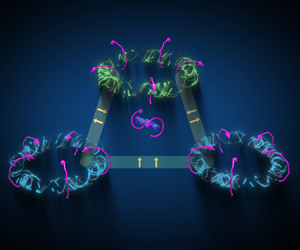
On the basis of the typical bubble and spike structures, we conclude that the development of interfacial instability can be investigated from the perspective of counter-rotating and co-rotating vortex pairs. When reshock occurs, which flow configurations are affected to reduce stability of the combined counter-rotating and co-rotating vortex pairs? It motivates us to explore the fundamental property of the flow structures and confirm the role of reshock for a rapid transition. For the sake of visual impression, we supply a pure schematic upon reshock selected from six typical instants in figure 1. In figure 1, the double-layer vortex rings are represented by blue and green toruses, respectively. The yellow twisted tubes denote the first-generation vortices, and the red elements denote the second-generation vortices with the double-layer vortex rings approaching each other. A schematic movie to show the basic flow structures and their evolution process after reshock is provided in the supplementary material available at https://doi.org/10.1017/jfm.2024.1220.
Schematic of the evolution process of double-layer swirling vortex rings upon reshock, from (a) to ( f).

The paper is organized as follows. In § 2, the DNS of the single- and multi-mode RMI via an open code OpenCFD are introduced. In § 3, three-dimensional double-layer vortex rings with the local swirl are studied, and the role of reshock in a rapid transition from the perspective of three-dimensional double-layer vortex rings with the local swirl is discussed. In § 4, we provide a description of the transition process from the large-, middle- and small-scale strain fields. Finally, conclusions are given in § 5.
2. Numerical simulations
To achieve a reasonable agreement with the experimental results conducted in a shock-tube facility, Leinov et al. (Reference Leinov, Malamud, Elbaz, Levin, Ben-Dor, Shvarts and Sadot2009) and Malamud et al. (Reference Malamud, Leinov, Sadot, Elbaz, Ben-Dor and Shvarts2014) suggested a suitable computational domain. During the late-time acceleration phase, the DT fuel density is larger than the plastic ablator density. Hence the reshock process is represented that the shock propagates from the heavy material into light material. This vital process is similar with the shock-tube experimental settings by Leinov et al. (Reference Leinov, Malamud, Elbaz, Levin, Ben-Dor, Shvarts and Sadot2009). So the same computational setting is used in our numerical simulations. The adopted computational domain and the grid numbers are listed in table 1. The  $x$-direction domain length is $L_x=0.085$ m for the multi-mode case, and $L_x=0.045$ m for the single-mode case. The $y$- and $z$-direction domain lengths are $L_y=L_z=0.01$ m for the single- and multi-mode cases. The computational configurations initiated by multi-mode perturbation are shown schematically in figure 2. We adopt a periodic boundary condition in the $y$- and $z$-directions, and an adiabatic wall boundary on the right-hand side of the main computational domain along the $x$-direction.
Initial parameter settings of the planar geometry.

Sketch diagram of the computational setting and initial conditions of the RMI with reshock.

The air and sulphur hexafluoride (SF $_6$) are located on the left- and right-hand sides of the initial perturbed interface, respectively. The initial shock Mach number $Ma$ is set to 1.2, propagating along the $x$-direction and then reflecting at the end wall. The initial pressure before the shock is $p_0=23\,000\,{\rm Pa}$, and the temperature is $T_0=298\,{\rm K}$. According to the Rankine–Hugoniot conditions, more physical variables can be obtained through the expressions (Tritschler et al. Reference Tritschler, Olson, Lele, Hickel, Hu and Adams2014a; Wong et al. Reference Wong, Livescu and Lele2019)
 \begin{gather} \rho_{air}^{\prime}=\rho_{{air }}\,\frac{(\gamma_{{air }}+1)\,Ma^{2}}{2+(\gamma_{{air }}-1)\,Ma^{2}}, \end{gather}
 \begin{gather} u_{air}^{\prime}=Ma\,c_{air}\left(1-\frac{\rho_{air}}{\rho_{air}^{\prime}}\right), \end{gather}
 \begin{gather} p_{air}^{\prime}=p_{air}\left(1+2\,\frac{\gamma_{air}}{\gamma_{air}+1}(Ma^{2}-1)\right), \end{gather}
where the sound speed is  $c_{air}=\sqrt {\gamma _{air}\,p_{air}/\rho _{air}}$, $\gamma _{air}=1.4$ and $\gamma _{SF_6}=1.1$. Here, $^{\prime }$ denotes the corresponding post-shock variables, $\rho _{air}$ is the density of the pre-shock air, $p_{air}$ is the pressure of the pre-shock air, and $\rho _{air}^{\prime }$, $u_{air}^{\prime }$ and $p_{air}^{\prime }$ are the post-shock density, velocity and pressure, respectively. The initial perturbed interface is generated via a random multi-mode narrowband power spectrum method, and it has been commonly used in the RMI academic community (Youngs Reference Youngs2004; Thornber et al. Reference Thornber, Drikakis, Youngs and Williams2010, Reference Thornber2017; Groom & Thornber Reference Groom and Thornber2019, Reference Groom and Thornber2021; Zhou, Groom & Thornber Reference Zhou, Groom and Thornber2020).
The random multi-mode narrowband power spectrum method is discussed briefly below. A perturbation power spectrum  $P(k)$ is assumed:
 \begin{equation} P(k)=\left\{\begin{array}{@{}ll@{}} C, & \text{when } k_{min }< k< k_{max }, \\[2pt] 0, & \text{otherwise}. \end{array}\right. \end{equation}
Here,  $k=\sqrt {k_{y}^{2}+k_{z}^{2}}$ is the perturbation wave vector, $k_{y}$ and $k_{z}$ denote the wave vectors in the $y$- and $z$-directions, respectively, and $k_{min}$ and $k_{max}$ are the minimum and maximum wavenumbers. The integral of the above perturbation power spectrum in spectral space is
 \begin{equation} \sigma^{2}=\int_{0}^{\infty} P(k) \,{\rm d} k=\frac{1}{2 {\rm \pi}} \int_{-\infty}^{\infty} \int_{-\infty}^{\infty} \frac{P(k)}{k} \,{\rm d} k_{y} \,{\rm d} k_{z}. \end{equation}
Hence for a mode  $\boldsymbol {k}$, its amplitude is $a(\boldsymbol {k})=\sqrt {P(k)/k}$.
Making an operation of the inverse Fourier transform on this relation, we can obtain
 \begin{equation} a(y, z)=\sum_{m, n={-}k_{max}}^{k_{max}} \operatorname{Re}\left\{c_{m, n} \exp \left[{\rm i} k_{0}(m y+n z)\right]\right\}, \end{equation}
where  $\operatorname {Re}$ denotes the real part of a complex number, $c_{m, n}$ is the amplitude of the mode number $m$ in the $y$-direction and the mode number $n$ in the $z$-direction, and $k_0=2 {\rm \pi}/L_y$.
By expanding (2.4) via the Euler formula and trigonometric relations, the perturbed amplitude can be written as
 $$\begin{align} A(y, z)&=\sum_{m,
n=0}^{N} a_{m, n} \cos (k_{0} m y) \cos (k_{0} n z) +b_{m, n} \cos
(k_{0} m y) \sin (k_{0} n
z)\nonumber\\
&\quad +c_{m, n} \sin (k_{0} m
y) \cos (k_{0} n z) +d_{m,
n} \sin (k_{0} m y) \sin
(k_{0} n z).
\end{align}$$
$$\begin{align} A(y, z)&=\sum_{m,
n=0}^{N} a_{m, n} \cos (k_{0} m y) \cos (k_{0} n z) +b_{m, n} \cos
(k_{0} m y) \sin (k_{0} n
z)\nonumber\\
&\quad +c_{m, n} \sin (k_{0} m
y) \cos (k_{0} n z) +d_{m,
n} \sin (k_{0} m y) \sin
(k_{0} n z).
\end{align}$$
These coefficients are generated randomly to satisfy the standard deviation at a given wavenumber  $k_{m,n}$ as follows:
 \begin{equation} \frac{1}{4}\left(\bar{a}_{m, n}^{2}+\bar{b}_{m, n}^{2}+\bar{c}_{m, n}^{2}+\bar{d}_{m, n}^{2}\right)=\frac{1}{2 {\rm \pi}}\,\frac{P(k_{m, n})}{k_{m, n}}\,\Delta k_{y}\,\Delta k_{z}. \end{equation}
The root mean square of the amplitude is set as  $0.1 \lambda _{min}$ in the present numerical simulation, and $\lambda _{min}=2 {\rm \pi}/k_{min}$. In addition, $k_{min}=8$ and $k_{max}=16$ in our numerical simulations.
A diffuse interface with gradient thickness  $\delta =L_y/32$ is employed to compute the mass fraction of SF $_6$ as
 \begin{equation} Y_{SF_6}(x, y, z)=\frac{1}{2}\left(1+\tanh \left(\frac{x-A(y, z)}{\delta}\right)\right), \end{equation}
where  $A(y, z)$ is the amplitude of the initial perturbed interface. The hyperbolic tangent function indicates that the gradient thickness $\delta$ only makes an apparent contribution around the perturbed interface.
The evolution of RMI can be described by the following three-dimensional compressible Navier–Stokes equations with multiple species of miscible gases:
 \begin{gather} \frac{\partial \rho}{\partial t}+\boldsymbol{\nabla}\boldsymbol{\cdot}( \rho \boldsymbol{{u}} )=0, \end{gather}
 \begin{gather} \frac{\partial \rho \boldsymbol{{u}}}{\partial t}+\boldsymbol{\nabla}\boldsymbol{\cdot}( \rho \boldsymbol{{u}} \boldsymbol{{u}} )={-}\boldsymbol{\nabla}( p \boldsymbol{\delta} - \boldsymbol{\sigma} ), \end{gather}
 \begin{gather} \frac{\partial E}{\partial t}+\boldsymbol{\nabla}\boldsymbol{\cdot}\left( \rho ( E+p ) \boldsymbol{{u}} \right)=\boldsymbol{\nabla}( \boldsymbol{\sigma}\boldsymbol{\cdot}\boldsymbol{{u}}+ \boldsymbol{{q}}), \end{gather}
 \begin{gather} \frac{\partial \rho Y_m}{\partial t}+\boldsymbol{\nabla}\boldsymbol{\cdot}( \rho Y_m \boldsymbol{{u}} )=\boldsymbol{\nabla}\boldsymbol{\cdot}( \rho D_m\,\boldsymbol{\nabla} Y_m ), \end{gather}
where  $\rho$ denotes the mixture density, $\boldsymbol {{u}}$ denotes the velocity vector, $p$ is the static pressure, and $\boldsymbol {\delta }$ is the Kronecker function. Here, $\boldsymbol {\sigma }$ is the viscous stress tensor for a Newtonian fluid without considering bulk viscosity, and $E$ is the total energy per unit volume. They are defined as
 \begin{equation} \sigma_{ij}=\mu\left( \frac{\partial u_i}{\partial x_j}+\frac{\partial u_j}{\partial x_i}-\frac{2}{3}\,\theta\delta_{ij} \right), \quad E=\frac{1}{2}\,\rho \boldsymbol{{u}}^2+\sum_{m=1}^N \rho_m h_m-p, \end{equation}
where  $\theta =\partial u_k / \partial x_k$ is the velocity divergence, $\mu$ is the mixture viscosity coefficient, $N$ denotes the total number of mixing species, $\rho _m$ is the $m$th-species density, and $h_m$ is the $m$th-species enthalpy. The conductive heat flux $\boldsymbol {q}$ can be computed according to Fourier's and Fick's laws as
 \begin{equation} \boldsymbol{q}=\kappa\,\boldsymbol{\nabla} T+ \rho\sum_{m=1}^N D_m h_m\,\boldsymbol{\nabla} Y_m, \end{equation}
where  $\kappa$ is the thermal conductivity of the mixture, $T$ is the temperature of the mixture, $D_m$ is the $m$th-species effective binary diffusion coefficient, and $Y_m$ is the $m$th-species mass fraction.
The  $m$th-species viscosity $\mu _m$ and thermal conductivity $\kappa _m$ can be computed by fitting polynomials from CHEMKIN (Kee, Rupley & Miller Reference Kee, Rupley and Miller1989) as follows:
 \begin{equation} \ln \mu_{m} =\sum_{n=1}^{N} a_{n, m}(\ln T)^{n-1}, \quad \ln \kappa_{m} =\sum_{n=1}^{N} b_{n, m}(\ln T)^{n-1}. \end{equation}
The fitting coefficients are listed in tables 2 and 3.
The fitting coefficients for viscosity.

The fitting coefficients for thermal conductivity.

Therefore, the mixture viscosity  $\mu$ and the thermal conductivity of the mixture $\kappa$ can be obtained as
 \begin{equation} \mu=\sum_{m=1}^N\frac{X_m \mu_m}{\sum_{j=1}^K X_j \varPhi_{mj}},\quad \kappa=\frac{1}{2}\left( \sum_{m=1}^N X_m \kappa_m+ \frac{1}{\sum_{m=1}^N X_m / \kappa_m } \right), \end{equation}
where
 \begin{equation} \varPhi_{mj}=\frac{1}{\sqrt{8}}\left( 1+\frac{M_m}{M_j} \right)^{{-}1/2}\left[ 1+\left( \frac{\mu_m}{\mu_j}\right)^{1/2}\left( \frac{M_j}{M_k} \right)^{1/4} \right]^2. \end{equation}
 For the mixture diffusion coefficient, the Schmidt number is assumed to be 1, defined as  $Sc_{m}=\mu /\rho D_m$ (Thornber & Zhou Reference Thornber and Zhou2012; Tritschler et al. Reference Tritschler, Zubel, Hickel and Adams2014b; Groom & Thornber Reference Groom and Thornber2019, Reference Groom and Thornber2021).
To obtain high-fidelity flow fields, a high-order finite difference code (OpenCFD) is employed to simulate the evolution of the RMI with reshock. In the numerical simulations with multi-mode perturbations, a sixth-order monotonicity-preserved optimized scheme is used to discretize the convective terms with the Lax–Friedrichs splitting method, and an eighth-order central difference scheme is employed to discretize the viscosity terms. For time marching, a third-order Runge–Kutta approach is used. This computational scheme has been validated successfully in applications involving multi-component diffusion, such as jet combustion (Fu et al. Reference Fu, Yu, Yan and Li2019), and cylindrical and spherical RMI (Li et al. Reference Li, Fu, Yu and Li2021b; Yan et al. Reference Yan, Fu, Wang, Yu and Li2022).
3. Three-dimensional double-layer vortex rings with the local swirl
3.1. Single-mode flow configuration
To investigate the three-dimensional flow structures, we first carry out DNS of single-mode RMI with reshock because of its simple and visual flow structures. The initial single-mode perturbation  $A(y,z)=A_0\cos (({2{\rm \pi} }/{\lambda })y)\cos (({2{\rm \pi} }/{\lambda })z)$ is adopted in the present numerical simulations, with $\lambda =0.005$ m and $A_0=0.04\lambda$. The computational parameters are listed in table 1. The bubble and spike positions are tracked along the shock-propagating direction according to their initial positions. Their difference is defined as the mixing width $h$, for the sake of the consistency with the following multi-mode analysis. It is exhibited in figure 3(a), which shows the increase of the mixing width after the first shock, and the decrease immediately after reshock. The outer-scale Reynolds number $Re_h$ is defined as $Re_h={h \dot {h}}/{\langle \nu \rangle }$. Here, $\dot {h}$ denotes the growth rate of the mixing width, $\nu$ is the kinematic viscosity coefficient, and $\langle \cdot \rangle$ denotes the ensemble average within the mixing regions. The circulation Reynolds number $Re_{\varGamma }$ is defined as $Re_{\varGamma }={\varGamma }/{\langle \nu \rangle }$, and $\varGamma$ is the circulation of half of a vortex ring. The temporal outer-scale and circulation Reynolds number evolutions are shown in figure 3(b), and they are approximately 650 after the first shock. In figure 4, the time evolution of the two-dimensional density field around the reshock time is shown, and the selected instants are marked in figure 3(a). Before reshock, the amplitude of the disturbed interface has increased to a relatively large value. It corresponds that the interaction of the interface and vortex-induced velocity may be strong to generate the second baroclinic vorticity (Peng et al. Reference Peng, Yang, Wu and Xiao2021a). When the reshock interacts with the mixing region, the mixing region is compressed first, accompanied by the occurrence of an inverse phase. After reshock, the mixing regions increase with increasing velocity. The single-mode flow configuration captures the dominant physical process, which enables the subsequent detailed analysis.
(a) The mixing width. (b) The outer-scale and circulation Reynolds numbers.

Two-dimensional contour slice of the mixture density initiated by a single-mode perturbation at different times: (a)  $t = 0.345\,{\rm ms}$, (b) $t = 0.375\,{\rm ms}$, (c) $t = 0.395\,{\rm ms}$, (d) $t = 0.415\,{\rm ms}$, (e) $t = 0.435\,{\rm ms}$, ( f) $t = 0.495\,{\rm ms}$.

For the instant before the reshock is selected, the vortex structures along with the bubble and spike structures are shown in figure 5. Three typical features of the flow structures are identified and summarized schematically in figure 6. For convenience in describing the flow structure evolution, a cylindrical coordinate system  $(r, \theta, z^\prime )$ is introduced. Here, $r$ denotes the radial direction, $\theta$ denotes the azimuthal direction, and $z^\prime$ denotes the axial direction. The relationships between the newly introduced cylindrical coordinates and the original Cartesian coordinates are $y=r\cos \theta$, $z=r\sin \theta$ and $x=z^\prime$. The three-dimensional configuration is shown in figure 6(a). The radial and axial dimensional configurations are shown in figure 6(b), and the azimuthal and axial dimensional configurations are shown in figure 6(c). The instantaneous translation velocity $\boldsymbol {U}$, circulation $\varGamma$, and swirling direction are determined from the relative motions of the double-layer vortex rings.
(a) Two-dimensional contour slice of the mixture density before reshock. (b) Three-dimensional vortex structures represented by  $Q=0.01Q_{max}$ rendered by the streamwise velocity, where $Q$ is the second invariant of the velocity gradient tensor.

(a) A pure three-dimensional schematic configuration to describe the coexistence of the co-rotating and counter-rotating vortices after reshock. The deformed tube represents the fluid elements between the co-rotating or counter-rotating vortices, and their shapes reflect the influence of the adjacent vortices. The arrows denote the external forces acting on the fluid elements. (b) Trajectories of double-layer point vortex pairs projected in the radial and axial directions ( $r,z^{\prime }$), with circulation $\varGamma$. The black straight arrows represent the instantaneous velocity induced by other point vortices within a layer, and the yellow straight arrows represent the instantaneous velocity induced by adjacent point vortices belonging to another layer. (c) Trajectories of double-layer point vortex pairs projected in the azimuthal and axial directions ( $\theta, z^{\prime }$).

First, the flow element is a torus that rotates around the torus centre. The rotation around the torus centre is reflected in the streamwise velocity difference within a torus in figure 5(b). According to the rotational symmetry in the azimuthal direction based on the two-dimensional configuration in figure 5(a), the three-dimensional torus can also be obtained. The three-dimensional rotation can be reduced to a two-dimensional local rotation around the torus centre, which is consistent with the two-dimensional configuration proposed by Balakumar et al. (Reference Balakumar, Orlicz, Ristorcelli, Balasubramanian, Prestridge and Tomkins2012). The streamline patterns of the horizontal layer are the same, forming counter-rotating vortex pairs. However, the streamline patterns of the vertical layer are opposite, and they form the co-rotating vortex pairs.
Second, two layers of vortex rings exist, and they are two planes perpendicular to the shock-propagating direction. These two layers are located around the bubble and spikes, respectively. The two layers of flow structures before reshock are shown in figure 5(b), represented by the white planes. This confirms that the double-layer characteristic is an intrinsic property of the RMI and that the second-layer vortex ring is induced by the first-layer vortex ring (Peng et al. Reference Peng, Yang, Wu and Xiao2021a; Peng, Yang & Xiao Reference Peng, Yang and Xiao2021b).
The swirl of a vortex ring is characterized by an azimuthal velocity (Gupta et al. Reference Gupta, Lilley and Syred1984), and it dominates turbulent mixing, transportation, drag and noise generation (Shariff Reference Shariff1992; Naitoh et al. Reference Naitoh, Okura, Gotoh and Kato2014; Leweke et al. Reference Leweke, Le Dizès and Williamson2016). The existence of swirling motion in the azimuthal direction can be proven from mathematical and physical perspectives. The existence of a steady solution of the Euler equation was investigated by Moffatt (Reference Moffatt1969), Turkington (Reference Turkington1989) and Grauer & Sideris (Reference Grauer and Sideris1991) to confirm the existence of the swirl. Due to elliptic instability or curvature instability, it is possible to generate swirl in the cores of initially non-swirling rings (Chang, Hertzberg & Kerr Reference Chang, Hertzberg and Kerr1997; Naitoh et al. Reference Naitoh, Fukuda, Gotoh, Yamada and Nakajima2002). In the present shocked-interface issue with a light–heavy distribution, after the interaction of the first shock wave and the disturbed interface, the transmitted and reflected shock waves are rippled. The transmitted and reflected rippled shock can be visualized by the disturbed pressure field shown in figure 7(a), which is selected at the instant ( $t=0.015$ ms) immediately after the first shock. Figure 7(b) shows the rippled shock wave and the disturbed interface, corresponding to the pink cuboid marked in figure 7(a). Subsequently, the rippled shock decays with oscillation, which leads to temporal-spatial non-homogeneity (Zou et al. Reference Zou, Liu, Liao, Zheng, Zhai and Luo2017, Reference Zou, Al-Marouf, Cheng, Samtaney, Ding and Luo2019). The temporal-spatial decay oscillation leads to the formation of three-dimensional characteristics. The post-shock flow field is disturbed, which is represented by the appearance of the spanwise velocity in the $x$–
$x$– $y$ plane. In figures 7(c) and 7(d), two-dimensional contour slices of the post-shock and post-reshock fields are presented, respectively. This finding confirms numerically the appearance of the spanwise velocity in the $x$–
$x$– $y$ plane. Hence the swirl motion of a vortex ring originates from the three-dimensional baroclinic process and rippled shock evolution. Notably, the swirl motion is local rather than global rigid rotation. The numerical results in figures 7(c,d) indicate that the swirl is relatively weak, with much smaller amplitude than the streamwise velocity. The local weak swirl motion of the vortex ring along with the translation velocity would induce the formation of small scales.
(a) Three-dimensional iso-surfaces of the disturbed pressure field, along with the shocked interface at  $t=0.015$ ms. (b) Three-dimensional rippled shock and shocked interface within the spatial region marked by the pink cuboid in (a). (c) Two-dimensional contour slice of the spanwise velocity at $t=0.125$ ms. (d) Two-dimensional contour slice of the spanwise velocity at $t=0.325$ ms. The black arrow marks the shock-propagating direction.

The swirling direction is associated with the translation of the vortex ring. This conclusion is based on the Bragg–Hawthorne equation with the Euler solution of the Hill spherical vortex (Bragg & Hawthorne Reference Bragg and Hawthorne1950). The alternative solution of the corresponding stream function  $\psi$ indicates that $\psi \sim U$, where $U$ is the vortex propagation velocity. From the energy method of a thin-cored swirling vortex ring, the vortex propagation velocity $U$ can be expressed as
 \begin{equation} U=\frac{\varGamma}{4 {\rm \pi}r_0}\left(\ln \frac{8 r_0}{a}-\frac{1}{2}+\frac{1}{\varGamma^2} \int_0^a \frac{\varGamma_\sigma^2-2 C_\sigma^2}{\sigma} \,\mathrm{d} \sigma\right), \end{equation}
where  $\varGamma =r u_\theta$, $r_0$ is the circular radius, $a$ is the cross-section radius, and $u_\theta$ is the azimuthal velocity in the cylindrical coordinate system. The detailed derivation process is presented in Appendices A and B. Within a three-dimensional vortex ring, the circulation of the extracted two-dimensional vortex pairs is opposite. According to the above theoretical derivation, the azimuthal velocity direction is also opposite. If we transfer the cylindrical coordinate system into the Cartesian coordinate system, then the perpendicular velocity directions of the two-dimensional vortex pairs are the same. The numerical results in figures 7(c,d) confirm this regulation.
In figure 8(a), we show the circulation of half of a vortex pair. After the first shock, the circulation increases rapidly because of the baroclinic process. The well-known Kelvin circulation theorem indicates that the circulation along any material loop is time-invariant if and only if the acceleration is curl-free (Wu, Ma & Zhou Reference Wu, Ma and Zhou2007). During the free evolution process of the mixing region, the dissipation and compressibility break the conservation law of the circulation, and the circulation after the first shock decreases slowly. The two-dimensional contour of the spanwise vorticity in figure 8(b) exhibits two peaks, which correspond to the first- and second-layer vortex rings. When the reshock interacts with the mixing region, the opposite baroclinic vorticity is induced. The opposite vorticity is visualized in figure 8(c), with positive and negative spanwise vorticity separated by the reshock. It is also reflected in figure 8(a).
(a) Circulation of half of a vortex pair. (b) Two-dimensional contour slices of the spanwise vorticity before reshock marked with a black circle in (a). (c) Two-dimensional contour slices of the spanwise vorticity when the reshock is inside the mixing regions marked with a red circle in (a).

The presence of the swirl in the azimuthal direction can cause the vortex ring to slow and alternatively increase its stability (Widnall Reference Widnall1972). The swirling effect on the translation velocity of a vortex ring is discussed briefly in Appendix B. However, the influence of the appearance of the swirl on the dynamics of a vortex ring depends on the swirl strength, the Reynolds number, the compactness of the vortex ring, etc. (Gupta et al. Reference Gupta, Lilley and Syred1984; Liang & Maxworthy Reference Liang and Maxworthy2005; Gargan-Shingles, Rudman & Ryan Reference Gargan-Shingles, Rudman and Ryan2016; Hattori, Blanco-Rodríguez & Le Dizès Reference Hattori, Blanco-Rodríguez and Le Dizès2019; He, Gan & Liu Reference He, Gan and Liu2020). The appearance of the swirl results in an azimuthal shear layer and centrifugal instability, which may lead to the small-scale generation. For a vortex ring without the swirl, the Kelvin–Helmholtz instability is reflected in the radial and axial dimensions, which is shown schematically in figure 6(b). However, the azimuthal shear layers induced by the swirl correspond to the azimuthal Kelvin–Helmholtz instability, and will modify the radial and axial Kelvin–Helmholtz instability without the swirl. The radial pressure gradient can be deduced from the reduced form of the radial momentum equation as
 \begin{equation} \frac{\partial p}{\partial r}=\frac{\rho u_\theta^2}{r}. \end{equation}
The radial pressure gradient play a role of centrifugal force, and the flow might experience the centrifugal instability. Hence for a weak swirl, the combined axial and azimuthal shear layers modify the Kelvin–Helmholtz instability appearing in the vortex ring without the swirl, and the evolving vortex ring becomes tilted. However, with increasing swirl, a central toroidal recirculation zone forms. When the swirl is strong enough, a strong wave is stabilized after the breakdown of the vortex ring. The travel distance of a vortex depends on the Reynolds number. When the Reynolds number is low, Naitoh et al. (Reference Naitoh, Okura, Gotoh and Kato2014) reported that the travel distance decreases with increasing swirl number. However, He, Gan & Liu (Reference He, Gan and Liu2019) concluded that the travel distance increases with increasing swirl number when the Reynolds number is relatively high.
Hence the three-dimensional effect is represented by decreasing the translation velocity for a single vortex ring. For the interfacial instability, this three-dimensional effect decreases the development of the mixing region while enhancing the degree of mixing. The swirling effect might explain the growth rate in three dimensions being slower than in two dimensions in RMI (Zhou Reference Zhou2017b). Nevertheless, the growth rate of the three-dimensional mixing regions might be faster than that of the two-dimensional mixing regions under some circumstances. The increasing mechanism is reflected in the induced translation velocity of the double-layer co-rotating vortex pairs, as shown schematically by the yellow straight arrows in figure 6(b). The stability of the swirling vortex ring ensures this successive increase mechanism. Hence three-dimensional effects are reflected in competitive decreasing and increasing mechanisms.
Third, the vertical co-rotating vortex pairs lead to strong shear between them, and the lower transition Reynolds number is easily satisfied during the interfacial evolution. We concluded that counter-rotating and co-rotating vortex pairs coexist during the development of a mixing region. The fluid element located around the centre of counter-rotating and co-rotating vortex pairs is affected by complex shear fields. The streamline patterns might lead to an alternative torque on the fluid element, which is shown schematically in figure 6(a). The external forcing acting on the fluid element inside the vortex pairs is complex, and the torque is one of the possible interactions. The large-scale strain induced by the double-layer co-rotating vortex pairs provides a successive source for triggering the transition to turbulent mixing.
3.2. Transition to turbulent mixing initiated by multiple modes
After reshock, the transition to turbulent flows has been confirmed in shock-tube experiments, whether with a single-mode perturbation or with a multi-mode perturbation (Mohaghar et al. Reference Mohaghar, Carter, Musci, Reilly, McFarland and Ranjan2017). The flow evolution initiated with a multi-mode perturbation shows finer scales, which is more appropriate for performing statistical analysis. Subsequently, we carry out multi-mode three-dimensional RMI with reshock through DNS, which can be analogous to experiments at late times. The multi-mode numerical settings refer to a previous shock-tube facility (Leinov et al. Reference Leinov, Malamud, Elbaz, Levin, Ben-Dor, Shvarts and Sadot2009).
3.2.1. Wave diagram and mixing width
The mass fraction  $Y$ and volume fraction $X$ of the heavy fluid SF $_6$ are defined as
 \begin{equation} Y=\frac{\rho_{SF_6}}{\rho}, \quad X=\frac{Y \mathcal{M}_{mix}}{\mathcal{M}_{SF_6}}. \end{equation}
Here,  $\mathcal {M}$ is the mean molecular weight. For the mixture, it is defined as (Kee et al. Reference Kee, Rupley and Miller1989)
 \begin{equation} \mathcal{M}_{mix}=\frac{1}{\sum_{i=1}^n Y_i/\mathcal{M}_i}. \end{equation}
 We compute the mean volume fractions of the heavy fluid SF $_6$ and light fluid air, and determine the bubble and spike positions with thresholds of 1 % and 99 % (Mikaelian Reference Mikaelian2005; Zhou Reference Zhou2017a,Reference Zhoub; Mikaelian & Olson Reference Mikaelian and Olson2020). The mixing centre is selected with $\langle X \rangle _{yz}=50\,\%$. Here, $\langle \cdot \rangle _{yz}$ denotes the ensemble average along the $y$- and $z$-directions. The displacements of the bubble, spike, mixing centre, shock, and rarefaction waves are shown in figure 9(a). From the initial status, the shock wave propagates in the streamwise direction and interacts with the perturbed interface for the first time. A shock wave is reflected and propagates in the opposite direction, and another shock wave is transmitted and propagates in the streamwise direction until it reaches the rigid wall. After the first interaction of shock and a perturbed interface, the interface accelerates and moves in the streamwise direction. Moreover, the perturbed modes also develop, and the mixing of light and heavy fluid occurs intensively. The obstacle of the rigid wall changes the propagation direction of the shock wave, and the reflected shock wave propagates in the opposite direction from the rigid wall. With shock-wave propagation, the second interaction of the developing interface and the shock wave occurs. The reshock leads to additional vorticity deposits on the developing interface, and may result in a rapid transition to turbulent mixing. To explore the rapid transition mechanism (Zhou Reference Zhou2017b), the changes in several typical parameters with reshock via DNS are investigated in this paper.
(a) Displacement of the bubble, spike, mixing centre and wave structures. (b) The mixing width, bubble height and spike height.

The mixing width  $h$ is obtained from the difference between the bubble and spike positions. The bubble height $h_b$ is computed as the difference between the bubble position and the mixing centre, and the spike height $h_s$ is computed as the difference between the mixing centre and the spike position. Their temporal evolutions are shown in figure 9(b). After reshock, the growth of the mixing width is linear, and the growth rate is approximately $23.1\, {\rm m}\,{\rm s}^{-1}$. The linear growth is consistent with the results of shock-tube experiments (Leinov et al. Reference Leinov, Malamud, Elbaz, Levin, Ben-Dor, Shvarts and Sadot2009; Malamud et al. Reference Malamud, Leinov, Sadot, Elbaz, Ben-Dor and Shvarts2014), which validate the present numerical simulations. The spike height to bubble height ratio is approximately $3\,:\,1$, which is consistent with other numerical results (Malamud et al. Reference Malamud, Leinov, Sadot, Elbaz, Ben-Dor and Shvarts2014).
The linear reshock model was proposed by Mikaelian (Reference Mikaelian1989) for three-dimensional multi-mode perturbations as
 \begin{equation} h=C_M A^+\,\Delta V\,t, \end{equation}
where  $A^+$ is the post reshock Atwood number ( $A^+=0.714$ in the present numerical simulation), $\Delta V$ is the velocity jump of the interface with reshock ( $\Delta V=95.4\,{\rm m}\,{\rm s}^{-1}$ in the present numerical simulation), $C_M$ is a constant, and the empirical coefficient is 0.28 on the basis of Rayleigh–Taylor experiments (Mikaelian Reference Mikaelian1989). However, it may depend on the Atwood number and other flow parameters. Dimonte & Schneider (Reference Dimonte and Schneider2000) and Oron et al. (Reference Oron, Arazi, Kartoon, Rikanati, Alon and Shvarts2001) proposed that $C_M$ ranges from 0.28 to 0.39. Leinov et al. (Reference Leinov, Malamud, Elbaz, Levin, Ben-Dor, Shvarts and Sadot2009) determined an average value $C_M=0.38$ according to shock-tube experiments. Ukai, Balakrishnan & Menon (Reference Ukai, Balakrishnan and Menon2011) also reported that $C_M=0.38$ via three-dimensional numerical simulations. Jacobs et al. (Reference Jacobs, Krivets, Tsiklashvili and Likhachev2013) reported that $C_M=0.26$ via membraneless reshock experiments. In our numerical simulations, we obtain $C_M \approx 0.34$, which is consistent with the experimental results (Leinov et al. Reference Leinov, Malamud, Elbaz, Levin, Ben-Dor, Shvarts and Sadot2009).
The Kolmogorov scale  $\eta$ is regarded as the smallest scale in classic turbulent theory (Pope Reference Pope2010; Tritschler et al. Reference Tritschler, Zubel, Hickel and Adams2014b; Li et al. Reference Li, He, Zhang and Tian2019, Reference Li, Tian, He and Zhang2021a), and is defined as
 \begin{equation} \eta=\left( \frac{\left\langle\nu\right\rangle^3}{\left\langle\epsilon\right\rangle} \right)^{{1}/{4}}, \end{equation}
where  $\epsilon$ is the viscosity dissipation rate of kinetic energy, which is defined as $\epsilon =\sigma _{i j} ({\partial u_i}/{\partial x_j})$. The criterion of DNS is whether the mesh spacing can resolve the Kolmogorov scale (Pope Reference Pope2010). Pope (Reference Pope2010) proposed that the mesh spacing should be less than twice that of the Kolmogorov scale. The ratio of the Kolmogorov scale and mesh spacing is shown in figure 10, and the ratio is larger than 0.5 except around the time when the shock wave interacts with the perturbed interface. This means that the current mesh resolution is sufficient to resolve the smallest scale. The computed Kolmogorov scale around the time when the shock wave interacts with the perturbed interface originates not only from the flow itself but also from the large velocity gradient induced by the shock wave. After the interaction of the shock wave and the perturbed interface, the Kolmogorov scale increases with the decay of turbulent fluctuations. The numerical results in figure 10 indicate that the Kolmogorov scale with the reshock is slightly less than that with the first shock. This finding confirms that additional small scales are generated by the reshock (Zhou Reference Zhou2017b).
The ratio of the Kolmogorov scale and mesh spacing for  $t_1=0.4\,{\rm ms}$ (middle time after the first shock), $t_2=0.7\,{\rm ms}$ (time before the reshock), $t_3=0.72\,{\rm ms}$ (time after the reshock) and $t_4=0.76 \,{\rm ms}$ (late time after the reshock).

3.2.2. The numerical configuration of the mixing transition to turbulent flows
For the multi-mode case, the apparent scale separation and high Reynolds number should satisfy the following transition criteria (Dimotakis Reference Dimotakis2000) for the characteristic length scale  $l$:
$l$:
 \begin{equation} \eta < \lambda_V < l < \lambda_L < \delta_L, \end{equation}
where  $\lambda _V \approx 50 \eta$ is the inner viscous scale, $\lambda _L = C_{lam} \lambda$ is the Liepmann–Taylor scale with $C_{lam} \approx 5$, and $\delta _L$ is the outer scale. Here, $\eta$ is the Kolmogorov viscous length scale, and $\lambda$ is the Taylor microscale. Apparent scale separation is needed for fully developed turbulent flows, which requires $\lambda _L > \lambda _V$ (Groom & Thornber Reference Groom and Thornber2021). The mixing transition phenomenon has been confirmed in many previous numerical simulations and shock-tube facilities. The directional Taylor microscales are shown in figure 11(a). The streamwise Taylor microscale after reshock increases to 200 times greater than the mesh spacing, and the transition criterion (3.7) can be satisfied easily. It can be concluded that a single shock may not be strong enough to induce a fully developed turbulent status, especially under the present initial small-amplitude perturbation and weak shock strength. At the same time, the reshock can deposit sufficient vorticity to result in three-dimensional fully developed turbulent flows via apparent scale separation.
(a) The ratio of the directional Taylor microscales and mesh spacing. (b) Transverse Taylor-scale Reynolds numbers and outer-scale Reynolds numbers.

Similarly, a transverse Taylor-scale and outer-scale Reynolds number can also be selected to estimate the transition process. The transverse Taylor-scale Reynolds number is defined as
 \begin{equation} Re_{\lambda_i}=\frac{\left\langle u_i^{\prime \prime 2}\right\rangle}{\left\langle\nu\right\rangle\sqrt{\left\langle\left(\partial u_i^{\prime \prime}/\partial x_i\right)^2\right\rangle}}. \end{equation}
Here,  $u_i^{\prime \prime }$ denotes the $i$th-direction fluctuating velocity, which is computed as $u_i^{\prime \prime }=u_i-\langle u_i \rangle$. We show the evolution of the transverse Taylor-scale Reynolds numbers and the outer-scale Reynolds number in figure 11(b). Dimotakis (Reference Dimotakis2000) proposed that $Re_{\lambda } \geq 100\unicode{x2013}140$ and $Re_h \geq 1\unicode{x2013}2\times 10^4$ for fully developed stationary turbulent flows. From the perspective of the transverse Taylor-scale Reynolds number, their values satisfy this requirement for a fraction of the time after the first shock and then decay. Under the effect of the reshock, they increase rapidly to be larger than 1000, and subsequently decay. Although the streamwise transverse Taylor-scale Reynolds number is always larger than the values in the other two directions, all are always greater than 140 during a fraction of the time after shock. The peak value of the outer-scale Reynolds number exceeds 400 after the first shock, and exceeds 4000 after reshock. However, it cannot satisfy the criterion with $Re_h \geq 1\unicode{x2013}2\times 10^4$ proposed by Dimotakis (Reference Dimotakis2000) and the minimum state with $Re_h \geq 1.6\times 10^5$ proposed by Zhou (Reference Zhou2007). Similar conclusions are also obtained in a previous work (Groom & Thornber Reference Groom and Thornber2021), and the main reason lies in the pollution of acoustic waves and imperfect boundary conditions in compressible numerical simulations, especially with a rigid wall on the right-hand side.
Before the transition to turbulent flows, the flow structure should be similar to that confirmed in numerical simulations with a single-mode perturbation. Hence we select an instance before reshock ( $t_2$) in figure 12(a) to show the three-dimensional flow structures. Owing to the complexity of the initial multi-mode perturbation, multiple-layer vortex rings are present within the mixing regions. The streamwise velocity difference shown in a single vortex ring corresponds to the streamwise translation through the self-induced velocity. In contrast to single-mode perturbations, the flow structures initiated with multi-mode perturbations are complex, including the vortex size, spatial distribution, and dependence on the bubble and spike structures. However, the basic flow structures are consistent with the vortex configuration shown in figure 6(a). The flow structures after the transition to turbulent flows are shown in figure 12(b). It is found that the dominant vortex rings have broken down into smaller scales, and they are similar to flow structures present in fully developed turbulent flows.
Three-dimensional vortex structures represented by  $Q=0.01Q_{max}$ rendered by the streamwise velocity (a) before reshock and (b) after reshock, initiated with multi-mode perturbations. The two selected instances correspond to $t_2$ and $t_4$ as marked in figure 10.

3.2.3. Enstrophy budget around the reshock time
The interaction of the shock and the perturbed interface can be explained as the baroclinicity of the density gradient and the pressure gradient, and it is regarded as an alternative origin for the RMI (Zhou et al. Reference Zhou2003; Zhou Reference Zhou2017b). This physical description can be expressed as the following vorticity governing equation (Chassaing et al. Reference Chassaing, Antonia, Anselmet, Joly and Sarkar2010; Yan et al. Reference Yan, Li, Wang and Yu2019, Reference Yan, Li, Yu and Wang2020; Bender et al. Reference Bender2021):
 \begin{equation} \frac{\partial \omega_{i}}{\partial t}+ u_{j}\,\frac{\partial \omega_{i}}{\partial x_{j}} = \omega_{j} S_{i j}- \frac{\partial u_{j}}{\partial x_{j}}\,\omega_{i}+\frac{1}{\rho^2}\,\epsilon_{i j k}\,\frac{\partial \rho}{\partial x_{j}}\,\frac{\partial p}{\partial x_{k}} + \epsilon_{i j k}\, \frac{\partial}{\partial x_{j}}\left(\frac{1}{\rho}\,\frac{\partial \sigma_{k l}}{\partial x_{l}}\right), \end{equation}
where  $\omega =\boldsymbol {\nabla }\times \boldsymbol {u}$ is the vorticity, $S_{ij}=(\partial u_i/\partial x_j +\partial u_j/\partial x_i)/2$ is the deformation strain rate tensor, and $\epsilon _{i j k}$ is the Levi-Civita symbol. An alternative definition of enstrophy in compressible flows is $\varOmega =\omega _{i}\omega _{i}/2$ (Bender et al. Reference Bender2021).
The governing equation can be derived as
 \begin{equation} \frac{\partial \varOmega}{\partial t}+u_{j}\,\frac{\partial \varOmega}{\partial x_{j}} = \underbrace{\omega_{j} S_{i j} \omega_{i}}_{VS} \underbrace{{}-2 \varOmega\,\frac{\partial u_{j}}{\partial x_{j}}}_{K_\varOmega}+\underbrace{\frac{\omega_{i}}{\rho^2}\,\epsilon_{i j k}\, \frac{\partial \rho}{\partial x_{j}}\,\frac{\partial p}{\partial x_{k}}}_{B} + \underbrace{\omega_{i} \epsilon_{i j k}\,\frac{\partial}{\partial x_{j}}\left(\frac{1}{\rho}\, \frac{\partial \sigma_{k l}}{\partial x_{l}}\right)}_{D_\varOmega}. \end{equation}
On the right-hand side, the first term is the vorticity stretching term labelled VS, which is associated with the energy cascade process in the classical turbulence theory (Pope Reference Pope2010). The second term originates from the compressibility, labelled  $K_\varOmega$, and the third term is the baroclinic term, labelled $B$. Kida & Orszag (Reference Kida and Orszag1990) proposed that the baroclinic mechanism works inside the curved shock, and vorticity stretching is dominant outside shocks. This means that the baroclinic term $B$ makes an essential contribution to the vorticity generation only when the shock interacts with the mixing regions, and the vorticity stretching term VS is dominant after the interaction of the shock and mixing regions.
The increased magnitude of the enstrophy is shown in figure 13(a), and it is investigated through the analysis of the enstrophy budget around the reshock time in figure 13(b). The definition of the enstrophy determines that its unit is  ${\rm s}^{-2}$, and the unit of its time derivative is ${\rm s}^{-3}$. To be consistent with the horizontal axis, the units of the enstrophy and its budget are changed to ${\rm m}{\rm s}^{-2}$ and ${\rm m}{\rm s}^{-3}$, respectively. The magnitude of the baroclinic term $B$ is smaller than the magnitude of the vorticity stretching term VS, whose contribution to the enstrophy evolution is more apparent. This regulation could be explained through the strong shear present in the definition of the vorticity stretching term VS and the co-rotating vortex pairs of the above double-layer vortex rings with local swirl. Around the first shock, the velocity gradient is small. However, the deformation stress tensor also develops with the development of the perturbed interface. Until the reshock time, the velocity fluctuation is much stronger than that with the first shock. Hence the vorticity stretching term makes an apparent contribution. The turbulent kinetic energy (TKE) is defined as ${\rm TKE}=\rho u_i^{\prime \prime }u_i^{\prime \prime }/2$, and its mean is also shown in figure 13(a). After reshock, its amplitude also increases rapidly, which is similar to the regulation of enstrophy (Tritschler et al. Reference Tritschler, Olson, Lele, Hickel, Hu and Adams2014a; Zhou et al. Reference Zhou, Groom and Thornber2020; Bender et al. Reference Bender2021).
(a) Mean enstrophy and turbulent kinetic energy. (b) The enstrophy budget and viscous dissipation rate of the kinetic energy ( $\langle \epsilon \rangle$) around the reshock time.

The determination of the transition time to turbulent mixing after reshock is an essential issue for practical applications, and the flow evolution after reshock is similar to that of decaying homogeneous and isotropic turbulence. Initiated by a random field, the flow fully develops after the viscous dissipation rate peaks in decaying homogeneous and isotropic turbulent flows. The characteristic time is the large-eddy turnover time, defined as  $\tau _i=L_{f_i}/u^{\prime }$. The directional integral length scale $L_{f_i}$ is
 \begin{equation} L_{f_i}=\frac{3{\rm \pi}}{2(u_i^{\prime})^2}\int_0^\infty\frac{E^u(k)}{k}\,{\rm d}k, \end{equation}
where  $E^u(k)$ is the power spectrum of the velocity, with $\int _0^{\infty }E^u(k)\,{\rm d}k=\langle u_i^{\prime 2} \rangle /2$, and $u_i^{\prime }$ is the root mean square of the $i$th directional velocity. The time evolution of the directional integral length scale and the corresponding large-eddy turnover time are shown in figure 14. After reshock, the ratio of the directional integral length scale and the Kolmogorov length scale increases rapidly, which represents large-scale separation. Moreover, the large-eddy turnover time decreases rapidly, which indicates a smaller characteristic time. Analogous to decaying homogeneous and isotropic turbulent flows, the large-eddy turnover time immediately after reshock can be used to predict the transition time. The average value of the three-directional large-eddy turnover time is approximately 0.073 ms. The peak viscous dissipation rate, which reflects the fully developed status, originates from the dominant strain field and is also associated with the vortex stretching process. Hence the time of developing vortex stretching is referred to as the characteristic time of mixing transition after reshock. This regulation is confirmed numerically in figure 13(b), with close peak times of the vortex stretching process and viscosity dissipation rate. The time from the reshock to the peak value of the viscosity dissipation rate is approximately 0.077 ms, which is close to the time predicted by the large-eddy turnover time method. Hence large-scale deposited vorticity is similar to decaying homogeneous and isotropic turbulent flows (Tritschler et al. Reference Tritschler, Zubel, Hickel and Adams2014b).
(a) Ratio of the directional integral length scale and the Kolmogorov length scale. (b) Corresponding directional large-eddy turnover times.

4. The description of the transition process from the strain field at large, middle and small scales
The highlighted transition to turbulent flows induced by reshock is the reshock that increases the instability of the involved counter-rotating and co-rotating vortex pairs, and accelerates the iterative cascade process. Under the joint influence of the counter-rotating and co-rotating vortex pairs, the flow evolution is unstable. After reshock, the deposited baroclinic is opposite, and the counter-rotating and co-rotating vortex pairs still coexist. Nevertheless, the vorticity increases dramatically from the deposited baroclinic vorticity, which corresponds to the increased rotation velocity around the vortex ring centre. Hence the Reynolds number increases rapidly and is larger than the critical Reynolds number of the vortex pairs. The evolution of the two-dimensional contour slice of the mixture density initiated by the single-mode perturbation is exhibited in figure 4 at different typical times. After reshock, the spike and bubble first move close to each other, and their phases are ultimately reversed. The relative motion introduces larger shear between the co-rotating vortex pairs, which triggers the transition to turbulent mixing (Goto Reference Goto2008; Leweke et al. Reference Leweke, Le Dizès and Williamson2016).
To summarize, it is the strong shear field that triggers the transition to turbulent mixing. In contrast to the short-time baroclinic term induced by reshock, strong shear destabilizes interface development during the transition to turbulent mixing, which occurs as a long-time source. The strong shear originates from the increased rotation velocity and decreased distance of the co-rotating and counter-rotating vortex pairs induced by reshock. Hence the reshock effect could be attributed to the generated large-scale strain field. The iterative interaction of the large-scale strain fields leads to the generation of next-generation vortices. To characterize the large-scale strain fields after reshock, we show in figure 15 the two-dimensional contour slices of the heavy gas (SF $_6$) density, enstrophy and amplitude of the strain rate tensor at the four selected instants marked in figure 10. Except for the instant immediately after reshock shown in figures 15(g–i), the spatial distributions of the enstrophy and strain fields are similar, with the development of the mixing region. The discrepancy lies in the characterization of the disturbed flow fields induced by the complex wave diagram. In figures 15(a–c), the transmitted and reflected shocks have passed away, and the induced perturbation into the flow field has dissipated over a sufficiently long period. Hence the difference between the spatial distributions of the enstrophy and strain fields is nearly negligible. A similar regulation is represented in the instant before the reshock in figures 15(d–f), except for the distribution of the reshock. This is due to the oscillating decreasing property of the rippled shock. In figures 15(j–l), after the interaction of the reshock and the mixing region, the reflected rarefaction wave also ripples. It also induces additional perturbation of the flow field after passing through, which is represented by the spatial distribution of the strain field on the right-hand side in figure 15(l). Nevertheless, the spatial distributions of the enstrophy and strain fields clearly differ immediately after reshock, as shown in figures 15(g–i). At this typical instant, the density field of the SF $_6$ in figure 15(g) indicates the compressed mixing region, and the large-scale flow structures dominate the subsequent flow evolution. However, the spatial distribution of the enstrophy in figure 15(h) is not sufficient to show the dominant large-scale property. The spatial distribution of the strain field in figure 15(i) indicates that the majority of the strain field is concentrated on large-scale structures, which is more evident in large-scale flow structures.
Two-dimensional contour slices of the heavy gas (SF $_6$) density, enstrophy and amplitude of the strain rate tensor, initiated by a multi-mode perturbation. They are shown at the selected instant $t_1$ in (a–c), at the selected instant $t_2$ in (d–f), at the selected instant $t_3$ in (g–i), and at the selected instant $t_4$ in (j–l), as marked in figure 10.

For the inertial scale, the self-amplification of the strain fields is the main contributor to the energy cascade process (Johnson Reference Johnson2020; Yang et al. Reference Yang, Fang, Fang, Pumir and Xu2022). The filtering technique can be used to investigate the scale interactions in turbulent flows. For any variable  $f$, the filtered field is expressed as $\bar {f}(\boldsymbol {x})=\int \,{\rm d}^3 \boldsymbol {{x}}\,G_l(\boldsymbol {{r}})\,f(\boldsymbol {x}+\boldsymbol {r})$. Here, $G_l(\boldsymbol {{r}})$ is a filter function, such as the box filter, Gaussian filter, sharp spectral filter, Cauchy filter or Pao filter (Pope Reference Pope2010). In compressible turbulent flows, the Favre filtered field considering the variable density is induced, which is expressed as $\tilde {f}=\bar {\rho f}/\bar {\rho }$ (Garnier, Adams & Sagaut Reference Garnier, Adams and Sagaut2009; Gatski & Bonnet Reference Gatski and Bonnet2013). The energy cascade process is reflected in the unclosed term of the governing equation of the large-scale kinetic energy ( $\bar {\rho }\tilde {u}_i^2/2$) as
 \begin{equation} \frac{\partial}{\partial t}\left(\frac{1}{2}\,\bar{\rho} \tilde{u}_i^2\right)+J_l={-}\varPi_l^t+\varPhi_l-D_l. \end{equation}
Here,  $J_l\equiv ({\partial }/{\partial x_j})(\tfrac {1}{2} \bar {\rho } \tilde {u}_i \tilde {u}_j+\bar {p} \tilde {u}_j+\bar {\rho } \tilde {\tau }_{i j} \tilde {u}_i-\tilde {u}_i \bar {\sigma }_{i j})$ is the spatial transportation term, $\varPi _l^t\equiv -\bar {\rho } \tilde {\tau }_{i j} ({\partial \tilde {u}_i}/{\partial x_j})$ is the interscale kinetic energy flux, $\varPhi _l\equiv \bar {p} ({\partial \tilde {u}_i}/{\partial x_i})$ is the pressure-dilatation term, and $D_l\equiv \bar {\sigma }_{i j} ({\partial \tilde {u}_i}/{\partial x_j})$ is the viscous dissipation term. For the kinetic energy cascade process term $\varPi _l^t$, previous valuable works have performed detailed statistical investigations of RMI (Thornber & Zhou Reference Thornber and Zhou2012; Liu & Xiao Reference Liu and Xiao2016; Zeng et al. Reference Zeng, Pan, Sun and Ren2018; Zhou, Ding & Cheng Reference Zhou, Ding and Cheng2024) and Rayleigh–Taylor instability (Cook & Zhou Reference Cook and Zhou2002; Zhao, Liu & Lu Reference Zhao, Liu and Lu2020; Luo & Wang Reference Luo and Wang2022; Wong et al. Reference Wong, Baltzer, Livescu and Lele2022; Zhao, Betti & Aluie Reference Zhao, Betti and Aluie2022).
To distinguish the contributions of the strain field and vortex stretching process to the kinetic energy cascade process, the subgrid-scale stress  $\bar {\rho }\tilde {\tau }$ can be expanded to the first-order approximation with an isotropic filter as (Eyink Reference Eyink2006; Garnier et al. Reference Garnier, Adams and Sagaut2009; Pope Reference Pope2010)
 \begin{equation} \bar{\rho}\tilde{\tau}=\bar{\rho}\left(\widetilde{u_i u_j}-\tilde{u}_i\tilde{u}_j\right)=\frac{l^2}{12}\,\bar{\rho}\frac{\partial \tilde{u}_i}{\partial x_k}\,\frac{\partial \tilde{u}_j}{\partial x_k}. \end{equation}
The above expression is also an adaptation of the tensor-diffusivity model of LES for compressible flows proposed by Vreman, Geurts & Kuerten (Reference Vreman, Geurts and Kuerten1995). A kinetic energy flux constraint model is also proposed based on the above expanded expression, which is employed to predict the transition process in compressible wall-bound turbulence (Yu et al. Reference Yu, Yuan, Qi, Wang, Li and Chen2022). The filtered velocity gradient can be decomposed into symmetric and antisymmetric components as
 \begin{equation} \frac{\partial \tilde{u}_i}{\partial x_j}=\tilde{S}_{ij}-\frac{1}{2}\,\epsilon_{ijk}\tilde{\omega}_k. \end{equation}
Here,  $\tilde {S}_{ij}=(\partial \tilde {u}_i / \partial x_j+\partial \tilde {u}_j / \partial x_i)/2$ is the filtered strain tensor. Substituting (4.3) and (4.2) into the interscale kinetic energy flux, we can obtain the expression
 \begin{equation} \varPi_l^t={-}\frac{l^2}{12}\,\bar{\rho}\,\frac{\partial \tilde{u}_i}{\partial x_k}\,\frac{\partial \tilde{u}_j}{\partial x_k}\,\frac{\partial \tilde{u}_i}{\partial x_j}\equiv \underbrace{-\frac{l^2}{12}\,\bar{\rho}\tilde{S}_{ik}\tilde{S}_{jk}\tilde{S}_{ij}}_{\varPi_l^S}\underbrace{{}-\frac{l^2}{48}\,\bar{\rho}\tilde{\omega}_i\tilde{S}_{ij}\tilde{\omega}_j}_{\varPi_l^\omega}. \end{equation}
On the right-hand side of the above expression, the first term  $\varPi _l^S$ originates from the strain field, and the second term $\varPi _l^\omega$ originates from the vortex stretching process. According to Betchov's relation, under incompressible and three-dimensional homogeneity conditions, the ensemble average of the first term is three times the ensemble average of the second term (Betchov Reference Betchov1956). The theoretical derivation indicates that the self-amplification of the strain-rate field contributes mainly to the kinetic energy cascade process rather than the vortex stretching process (Carbone & Bragg Reference Carbone and Bragg2020; Johnson Reference Johnson2020; Johnson & Wilczek Reference Johnson and Wilczek2024).
The statistical properties of the kinetic energy flux and the contributions from the strain field and vortex stretching process are subsequently investigated. We show their ensemble averages at different length scales along the streamwise direction in the focused four instants in figure 16. All the statistical results illustrate that the vortex stretching process plays a less dominant role in the kinetic energy cascade process, which is represented by the smaller amplitudes of the kinetic energy flux contributed by the vortex stretching process shown in figures 16(c, f,i,l). At relatively large scales, the forward kinetic energy cascade occurs mainly within the spike region, and the backward kinetic energy cascade process occurs mainly within the bubble regions. This conclusion is consistent with previous regulations (Thornber & Zhou Reference Thornber and Zhou2012; Liu & Xiao Reference Liu and Xiao2016; Zhou et al. Reference Zhou, Ding and Cheng2024), but it does not apply immediately after reshock, as shown in figure 16(g). Immediately after reshock, the backward kinetic energy cascade process dominates the bubble and spike regions, except around the mixing centre. This reflects the large-scale flow structure generation process during the compression stage induced by the reshock. With the development of the mixing region after reshock, the forward kinetic energy cascade process begins to be important, which is shown first around the mixing centre, and then extended to the spike regions. At relatively small scales, the forward kinetic energy cascade process is dominant. Hence a critical length scale exists for the bubble regions. The numerical results shown in figure 16 indicate that the critical length scale is approximately  $10\,\Delta x \unicode{x2013} 20\,\Delta x$, which is associated with the initial perturbation distribution.
The mean total kinetic energy flux  $\langle \varPi _l^t\rangle _{yz}$, the mean kinetic energy flux contributed from the strain fields $\langle \varPi _l^S\rangle _{yz}$, and the mean kinetic energy flux contributed from the vortex stretching process $\langle \varPi _l^\omega \rangle _{yz}$, at different length scales along the streamwise direction. They are shown at the selected instant $t_1$ in (a–c), at the selected instant $t_2$ in (d–f), at the selected instant $t_3$ in (g–i), and at the selected instant $t_4$ in (j–l), as marked in figure 10. The three black dashed lines from left to right correspond to the spike position, mixing centre and bubble position, respectively.

As the two components of the first-order approximation of the kinetic energy flux, the theoretical relationship of their ensemble average under the three-dimensional homogeneity condition illustrates that the contribution from the strain field is dominant. In figure 16, their ensemble average at different length scales is also presented along the streamwise direction. Although the amplitude discrepancy of the total kinetic energy flux and the contribution from the strain fields exist, the spatial and scale distributions are similar, including the dependence of the kinetic cascade process on the bubble and spike regions, and the critical length scale separating the forward and backward kinetic energy cascade processes. The contribution from the vortex stretching process is small, which indicates a large deviation in predicting the kinetic energy cascade process. The amplitude discrepancy validates the conclusion that self-amplification of the strain rate field contributes mainly to the kinetic energy cascade process. In addition, the vortex stretching process cannot capture the inverse kinetic energy cascade process, which is reflected in the negative values within the bubble regions. Immediately after reshock, the vortex stretching process cannot capture the compression process of the mixing regions. Nevertheless, the vortex stretching process can qualitatively reflect the forward kinetic energy cascade process at small scales, even when the amplitude discrepancy is still large.
To further quantitatively investigate the total kinetic energy flux and contributions from the strain field and vortex stretching process, their ensemble averages and ensemble averages conditioned in bubble and spike regions with different length scales at the four focused instants are shown in figure 17. These ensemble averages along the streamwise directions are similar to the regulations shown in figure 16. At relatively large scales, the cancellation of the forward kinetic energy cascade in the spike region, and backward kinetic energy cascade in the bubble region, leads to a small value of the ensemble average of the kinetic energy flux with the mixing regions. Hence the kinetic energy cascade process should be associated with specific flow structures. The ensemble averages of the kinetic energy flux within the mixing regions cover the coexistence of the forward and backward kinetic energy cascade processes. This regulation indicates the potential value of the tensor-diffusivity model in the application of modelling the RMI with multiple shocks, even when facing possible numerical instability. However, the pure dissipative model, such as the Smagorinsky model with a constant coefficient, might not be appropriate for predicting RMI evolution. This statistical regulation indicates the use of a combined LES model to predict the RMI evolution with multiple shocks. This means that the Smagorinsky model can be employed at middle length scales to capture the kinetic energy cascade process and provide numerical stability, and the tensor-diffusivity model can be employed at large length scales to capture the kinetic energy cascade process.
The mean total kinetic energy flux within the mixing region  $\langle \varPi _l^t\rangle$, within the bubble region $\langle \varPi _l^t \mid {\rm bubble} \rangle$, and within the spike region $\langle \varPi _l^t \mid {\rm spike} \rangle$; the mean kinetic energy flux contributed from the strain fields within the mixing region $\langle \varPi _l^S\rangle$, within the bubble region $\langle \varPi _l^S \mid {\rm bubble} \rangle$, and within the spike region $\langle \varPi _l^S \mid {\rm spike} \rangle$; and the mean kinetic energy flux contributed from the vortex stretching process within the mixing region $\langle \varPi _l^\omega \rangle$, within the bubble region $\langle \varPi _l^\omega \mid {\rm bubble} \rangle$, and within the spike region $\langle \varPi _l^\omega \mid {\rm spike} \rangle$, at different length scales. They are shown at the selected instant $t_1$ in (a), at the selected instant $t_2$ in (b), at the selected instant $t_3$ in (c), and at the selected instant $t_4$ in (d), as marked in figure 10.

Hence the rapid transition in RMI can be described from the perspective of strain field at large, middle and small scales, respectively. At large scales, reshock induces short-time, large-scale baroclinic vorticity, which intensifies the motion of the co-rotating vortex pairs. It provides a large-scale strain field, which also serves as a source to sustain the multiscale kinetic energy distribution. At middle scales, self-amplification of the middle-scale strain field transfers kinetic energy from large scales to small scales. At small scales, viscous dissipation is directly associated with the strain fields. To estimate the multiscale distributions around the reshock time, we select four typical instants, marked in figure 10, to show the kinetic energy spectrum in figure 18. Before reshock, the total kinetic energy spectrum decays at all scales. Immediately after reshock, the amplitude of the kinetic energy density increases dramatically, which originates from the large-scale deposited baroclinic vorticity. The energy spectra density slope is relatively large, which means that large-scale generation is dominant. Nevertheless, the kinetic energy transfers from large to small scales after sufficient time. The energy spectra density slope is consistent with that of the classical developed turbulent flows, which corresponds to the iterative cascade of the strain fields induced by reshock. The three-dimensional iso-surfaces of the mass fraction of SF $_6$ with $Y =0.99$ at different corresponding times with figure 18 are shown in figure 19. Consistent with the two-dimensional flow configurations in figure 15, the three-dimensional mixing regions in figures 19(a,b) can reflect the dissipation of the small scales from $t_1$ to $t_2$. Figure 19(c) shows the mixing region decompressed by reshock, and a fully developed mixing region is shown in figure 19(d).
Kinetic energy spectra initiated by a multi-mode perturbation at different times, where  $\varPi$ is the energy flux, $S$ is the strain field, $\tilde {S}$ is the large-scale strain field, $\epsilon$ is the viscous dissipation rate, and $\nu$ is the kinematic viscosity coefficient.

Three-dimensional iso-surfaces of the mass fraction of the heavy gas (SF $_6$) with $Y=0.99$. The instant is $t_1$ in (a), $t_2$ in (b), $t_3$ in (c) and $t_4$ in (d).

5. Conclusions and discussion
In this paper, we carry out three-dimensional DNS of the RMI with reshock initiated with single- and multi-mode perturbations, and investigate the transition process in the RMI with reshock from the perspective of three-dimensional double-layer swirling vortex rings. We extend the two-dimensional flow configuration to three dimensions by extending the flow in the azimuthal direction, and investigate the evolution of the local swirling vortex rings around the reshock time, which are located around the bubble and spikes. The three-dimensional effect is represented by the local swirling motion in the azimuthal direction, which originates from the three-dimensional rippled shock. This decreases the translation velocity of a vortex ring, which might cause the mixing region to slow in practical three-dimensional flows. Nevertheless, the double-layer co-rotating vortex pair could increase the translation velocity of a vortex ring. The stability of the swirling vortex ring ensures the successive increasing mechanism induced by the double-layer co-rotating vortex pair. Hence increasing and decreasing mechanisms exist to form three-dimensional effects relative to two-dimensional flows.
The coexistence of co-rotating and counter-rotating vortices provides the possibility of triggering a rapid transition, and they are common flow structures within the scope of interfacial mixing. We describe the rapid transition in RMI from the perspective of strain field at large, middle and small scales, which provides a straightforward physical configuration to uncover what happens during the mixing transition process. At large scales, the reshock leads to large-scale vorticity deposition, which intensifies the evolution of the vortex rings. The translation velocity difference of the double-layer vortex rings induced by reshock causes them to approach each other, and the corresponding shear field increases rapidly. The increased shear field serves as a large-scale source to trigger turbulent mixing. At middle scales, self-amplification of the strain field dominates, and apparent scale separation is present after a typical characteristic time. At small scales, the strain field is directly associated with the viscous dissipation process. Based on the similarity between the flow evolution of RMI with reshock and decaying homogeneous and isotropic turbulent flows, we confirm that the large-eddy turnover time can be selected as the characteristic time to determine the characteristic time of the transition process. It can provide practical suggestions for the strategy design of implosion experiments and exploration of supernovas.
The present numerical simulations and corresponding analysis are based on the shock propagating from heavy material into light material, which is similar with the flow evolution during the late-time acceleration phase in ICF. Nevertheless, we investigate the rapid transition process from the fluid and mixing evolution, and the shock Mach number is small. In the future, more factors associated with the high-energy-density conditions should be investigated to give a more comprehensive estimation of the implosion process in ICF.
Supplementary material
Supplementary material is available at https://doi.org/10.1017/jfm.2024.1220.
Acknowledgements
All the numerical simulations were performed on supercomputers in China.
Funding
This work is funded by the National Natural Science Foundation of China (grant nos 12302281 and 12105022) and the National Key R&D Program of China (no. 2023YFA1608400). Z.Y. is also supported by the China Postdoctoral Science Foundation (no. 2022M710459).
Declaration of interests
The authors report no conflict of interest.
Appendix A. The steady solution of the Bragg–Hawthorne equation
It is often convenient to use a cylindrical coordinate system  $(r,\theta,z)$ to describe the geometric characteristics of a vortex ring, with velocity $\boldsymbol {u}=(u,v,w)$ and vorticity $\boldsymbol \omega =(\omega _r,\omega _\theta,\omega _z)$. The three vorticity components are
 \begin{equation} \omega_{r}=\frac{1}{r}\,\frac{\partial w}{\partial\theta}-\frac{\partial v}{\partial z},\quad\omega_{\theta}=\frac{\partial u}{\partial z}-\frac{\partial w}{\partial r},\quad\omega_{z}=\frac{1}{r}\,\frac{\partial(rv)}{\partial r}-\frac{1}{r}\,\frac{\partial u}{\partial\theta}. \end{equation}
 We introduce a Stokes stream function  $\psi$ and a scalar function $\varGamma =rv$ to express the velocity and vorticity as
 \begin{gather} u={-}\frac{1}{r}\,\frac{\partial\psi}{\partial z},\quad w=\frac{1}{r}\,\frac{\partial\psi}{\partial r}, \end{gather}
 \begin{gather} \omega_{r} ={-}\frac{1}{r}\,\frac{\partial\varGamma}{\partial z},\quad \omega_{z} =\frac{1}{r}\,\frac{\partial\varGamma}{\partial r},\quad \omega_{\theta} ={-}\left[\frac{\partial}{\partial r}\left(\frac{1}{r}\,\frac{\partial\psi}{\partial r}\right)+\frac{1}{r}\,\frac{\partial^{2}\psi}{\partial z^{2}}\right]. \end{gather}
The inviscid azimuthal momentum equation of the Crocco–Vazsonyi equation reads as
 \begin{equation} \frac{\partial v}{\partial t}+\left(u \omega_z-w \omega_r\right)={-}\frac{1}{r}\,\frac{\partial H}{\partial \theta}, \end{equation}
where  $H=p+\tfrac {1}{2}u^2$. The corresponding inviscid azimuthal vorticity equation reads as
 \begin{equation} \frac{\mathrm{D} \omega_\theta}{\mathrm{D} t}+\frac{v \omega_r}{r}=\boldsymbol{\omega} \boldsymbol{\cdot} \boldsymbol{\nabla} v+\frac{\omega_\theta u}{r}. \end{equation}
Here,
 \begin{equation} \frac{\mathrm{D}}{\mathrm{D} t}=\frac{\partial}{\partial t}+u\,\frac{\partial}{\partial r}+\frac{v}{r}\,\frac{\partial}{\partial \theta}+w\,\frac{\partial}{\partial z}. \end{equation}
 According to the definition of the scalar function  $\varGamma =rv$, we can obtain its governing equation as
 \begin{equation} \frac{\mathrm{D} \varGamma}{\mathrm{D} t}=\nu\left[r\,\frac{\partial}{\partial r}\left(\frac{1}{r}\, \frac{\partial \varGamma}{\partial r}\right)+\frac{\partial^2 \varGamma}{\partial z^2}\right]. \end{equation}
The inviscid azimuthal vorticity equation can be rewritten as
 \begin{equation} \frac{\mathrm{D}}{\mathrm{D} t}\left(\frac{\omega_\theta}{r}\right)=\nu\left({\nabla}^2+\frac{2}{r}\, \frac{\partial}{\partial r}\right)\left(\frac{\omega_\theta}{r}\right)+\frac{1}{r^4}\,\frac{\partial \varGamma^2}{\partial z}. \end{equation}
If we suppose that the fluid is incompressible and inviscid, then the steady flow must be generalized to the Beltramian. The above equations can be reduced to
 \begin{gather} \boldsymbol{u} \boldsymbol{\cdot} \boldsymbol{\nabla} \varGamma=0, \end{gather}
 \begin{gather} \boldsymbol{u} \boldsymbol{\cdot}\left(\frac{\omega_\theta}{r}\right)=\frac{1}{r^4}\frac{\partial \varGamma^2}{\partial z}. \end{gather}
This indicates that the circulation along any circle around the vortex axis is conserved, and that  $\varGamma =C(\psi )$. The vorticity can be expressed as
 \begin{align} \omega_r={-}\frac{1}{r}\,\frac{\mathrm{d} C}{\mathrm{d} \psi}\,\frac{\partial \psi}{\partial z}=u\, \frac{\mathrm{d} C}{\mathrm{d} \psi},\quad \omega_z=\frac{1}{r}\,\frac{\mathrm{d} C}{\mathrm{d} \psi}\,\frac{\partial \psi}{\partial r}=w\,\frac{\mathrm{d} C}{\mathrm{d} \psi},\quad \frac{\omega_\theta}{r}=\frac{C}{r^2}\,\frac{\mathrm{d} C}{\mathrm{d} \psi}-\frac{\mathrm{d} H}{\mathrm{d} \psi}. \end{align}
Therefore, the following differential equation can be obtained for steady inviscid flows:
 \begin{equation} r\,\frac{\partial}{\partial r}\left(\frac{1}{r}\,\frac{\partial \psi}{\partial r}\right)+\frac{\partial^2 \psi}{\partial z^2}=r^2\,\frac{\mathrm{d} H}{\mathrm{d} \psi}-C\, \frac{\mathrm{d} C}{\mathrm{d} \psi} . \end{equation}
This equation is called the Bragg–Hawthorne equation (Bragg & Hawthorne Reference Bragg and Hawthorne1950; Saffman Reference Saffman1995; Wu et al. Reference Wu, Ma and Zhou2007). The Euler solution of the Hill spherical vortex can be extended to apply to the Bragg–Hawthorne equation. In spherical coordinates  $(r, \theta, \phi )$ with $r< a$, a closed-form solution exists with $C(\psi )=\pm \alpha \psi$ and $H=H_0+\lambda \psi$. An alternative solution of the stream function is
 \begin{equation} \psi={-}\frac{1}{2}U\left(r^2-\frac{a^3}{r}\right)\sin\theta, \end{equation}
where  $U$ is the speed at which the vortex propagates relative to the fluid at infinity (Moffatt Reference Moffatt1969).
Appendix B. The swirling effect on the translation velocity and kinetic energy of a vortex ring
From (A11a–c), the stream function can be obtained as
 \begin{equation} \psi(r, z)=\frac{1}{4 {\rm \pi}} \int \frac{r \omega_\theta^{\prime} \boldsymbol{e}_\theta^{\prime} \boldsymbol{\cdot} \boldsymbol{e}_\theta}{R}\,\mathrm{d} V^{\prime}, \quad R=|\boldsymbol{x}-\boldsymbol{x}^{\prime}| . \end{equation}
It can also be rewritten as
 \begin{equation} \psi(r, z)=\int \omega_\theta\,G\left(r, r^{\prime}, z-z^{\prime}\right) \mathrm{d} r^{\prime} \,\mathrm{d} z^{\prime}, \end{equation}
where
 \begin{align} & G(r, r^{\prime},
z-z^{\prime}) =\frac{r r^{\prime}}{4 {\rm \pi}} \int_0^{2 {\rm \pi}}
\frac{\cos \beta}{R} \,\mathrm{d} \beta,\nonumber \\
&\beta=\theta-\theta^{\prime},\
R=\sqrt{(z-z^{\prime})^2+r^2+r^{\prime 2}-2 r r^{\prime}
\cos \beta}.
\end{align}
\begin{align} & G(r, r^{\prime},
z-z^{\prime}) =\frac{r r^{\prime}}{4 {\rm \pi}} \int_0^{2 {\rm \pi}}
\frac{\cos \beta}{R} \,\mathrm{d} \beta,\nonumber \\
&\beta=\theta-\theta^{\prime},\
R=\sqrt{(z-z^{\prime})^2+r^2+r^{\prime 2}-2 r r^{\prime}
\cos \beta}.
\end{align}The kinetic energy can be expressed as
 \begin{equation} K=2 U I_z+2 {\rm \pi}\int\left[\omega_\theta(r w-z u)+v(z \omega_r-r \omega_z)\right] r \,\mathrm{d} r \,\mathrm{d} z. \end{equation}
By introducing the vorticity-induced kinetic energy and Lamb's first formula, we can obtain the following exact relations:
 \begin{equation} \left. \begin{gathered} {\rm \pi}\int \omega_\theta \psi r \,\mathrm{d} r \,\mathrm{d} z =2 U I_z+2 {\rm \pi}\int \omega_\theta(r w-z u) r \,\mathrm{d} r \,\mathrm{d} z,\\ I_z =\frac{1}{2} \int \omega_\theta r^2 \,\mathrm{d} r \,\mathrm{d} z \,\mathrm{d} \theta, \\ 2 {\rm \pi}\int \omega_\theta(r w-z u) r \,\mathrm{d} r \,\mathrm{d} z =2 {\rm \pi}\int(r v^2-3 r z u \omega_\theta) \,\mathrm{d} r \,\mathrm{d} z. \end{gathered} \right\} \end{equation}
The following notations are introduced to use the energy method for computing the thin-cored swirling vortex ring:
 \begin{equation} \left. \begin{gathered} \varGamma_\sigma(\sigma) =2 {\rm \pi}\int_0^\sigma \omega_\theta(\sigma^{\prime})\, \sigma^{\prime} \,\mathrm{d} \sigma^{\prime}, \quad \omega_\theta(\sigma)\,\sigma \,\mathrm{d} \sigma=\frac{1}{2 {\rm \pi}} \,\mathrm{d} \varGamma_\sigma,\\ \varGamma_\sigma(a) \equiv \varGamma, \quad u =\frac{\varGamma_\sigma}{2 {\rm \pi}\sigma} \cos \alpha, \quad v=v(\sigma) \equiv \frac{C_\sigma(\sigma)}{2 {\rm \pi}\sigma}. \end{gathered} \right\} \end{equation}
Therefore, the above exact relations can be expressed as
 \begin{equation} \left. \begin{gathered} I_z ={\rm \pi} \int(r_0+\sigma \sin \alpha)^2\,\omega_\theta(\sigma)\,\sigma \,\mathrm{d} \sigma \,\mathrm{d} \alpha \approx {\rm \pi}\varGamma r_0^2,\\ \psi(\sigma) =\frac{r_0 \varGamma}{2 {\rm \pi}}\left(\ln \frac{8 r_0}{a}-2\right)+\frac{r_0}{2 {\rm \pi}} \int_\sigma^a \frac{\varGamma_s}{s} \,\mathrm{d} s,\\ {\rm \pi}\int \omega_\theta \psi \sigma \,\mathrm{d} \sigma \,\mathrm{d} \alpha \approx \frac{1}{2}\, r_0 \varGamma^2\left(\ln \frac{8 r_0}{a}-2\right)+\frac{r_0}{2} \int_0^a \frac{\varGamma_\sigma^2}{\sigma} \,\mathrm{d} \sigma. \end{gathered} \right\} \end{equation}
To leading order,
 \begin{equation} 2 {\rm \pi}\int r v^2 \,\mathrm{d} r \,\mathrm{d} z=r_0 \int_0^a \frac{C_\sigma^2}{\sigma} \,\mathrm{d} \sigma, \quad 6 {\rm \pi}\int r z u \omega_\theta \,\mathrm{d} r \,\mathrm{d} z=\frac{3}{4}\,r_0 \varGamma^2 . \end{equation}
Finally, we obtain the translation velocity and kinetic energy of a vortex ring as follows:
 \begin{gather} U=\frac{\varGamma}{4 {\rm \pi}r_0}\left(\ln \frac{8 r_0}{a}-\frac{1}{2}+\frac{1}{\varGamma^2} \int_0^a \frac{\varGamma_\sigma^2-2 C_\sigma^2}{\sigma} \,\mathrm{d} \sigma\right), \end{gather}
 \begin{gather} K=\frac{1}{2}\,r_0 \varGamma^2\left(\ln \frac{8 r_0}{a}-2+\frac{1}{\varGamma^2} \int_0^a \frac{\varGamma_\sigma^2+C_\sigma^2}{\sigma} \,\mathrm{d} \sigma\right), \end{gather}
where  $C_\sigma ^2$ reflects the swirling contribution. These findings indicate that the swirling direction is associated with the translation direction of the vortex rings, and the appearance of the swirling motion would cause the vortex ring to slow and increase the kinetic energy (Grauer & Sideris Reference Grauer and Sideris1991; Cheng, Lou & Lim Reference Cheng, Lou and Lim2010; Naitoh et al. Reference Naitoh, Okura, Gotoh and Kato2014).


 Open access