


1 Introduction
For accurate zonation and risk assessment, it is important to accurately predict the distance to which hazardous particulate natural flows such as debris flows, pyroclastic flows or snow slab avalanches might travel (Dalbey et al. Reference Dalbey, Patra, Pitman, Bursik and Sheridan2008). These flows are heavily influenced not only by the basal topography, but also by the mixture properties, such as water saturation and the size distribution of the particulate components (e.g. snow, pumice, rock, sand). Large-scale experiments performed by Iverson et al. (Reference Iverson, Logan, Lahusen and Berti2010) showed that segregation effects significantly increase the run-out distance of granular flows over inclined planes (chute flows). On the laboratory scale, experiments also show that granular flows of mixtures behave differently than flows of uniform materials, exhibiting interesting fingering effects (Pouliquen & Vallance Reference Pouliquen and Vallance1999; Vallance & Savage Reference Vallance and Savage2000; Baker, Johnson & Gray Reference Baker, Johnson and Gray2016).
Size segregation can have a very strong effect on a mixture’s composition, and often leads to a nearly complete separation of the different particle phases. For granular chute flows this tends to un-mix particles of different sizes into layers, creating an inversely graded structure; the larger particles tend to segregate to the upper free surface, while the smaller particles sink to the base (Middleton Reference Middleton1970). Although there is usually some degree of diffusive remixing (Gray & Chugunov Reference Gray and Chugunov2006), in the bidisperse granular chute flows we consider here, layers of pure large and pure small particles develop, with only a thin layer of mixed material in between (Savage & Lun Reference Savage and Lun1988).
There are many mechanisms of size segregation in granular flows (Dippel & Luding Reference Dippel and Luding1995; Luding et al. Reference Luding, Clément, Rajchenbach and Duran1996; Jenkins Reference Jenkins1998; Mullin Reference Mullin2000; Hong, Quinn & Luding Reference Hong, Quinn and Luding2001; Mobius et al. Reference Mobius, Lauderdale, Nageland and Jaeger2001; Jenkins & Yoon Reference Jenkins and Yoon2002; González et al. Reference González, Windows-Yule, Luding, Parker and Thornton2015; Windows-Yule et al. Reference Windows-Yule, Scheper, van der Horn, Hainsworth, Saunders, Parker and Thornton2016), but kinetic sieving and squeeze expulsion are the mechanisms that are often used to describe segregation in dense granular chute flows (Middleton Reference Middleton1970; Savage & Lun Reference Savage and Lun1988; Vallance & Savage Reference Vallance and Savage2000). In this description, void spaces open up between particles, allowing for percolation downwards. Small particles are more likely to fall into these gaps, which leads to a movement of small particles towards the base of the flow. At the same time, force imbalances squeeze all particles out of their layers towards the free surface, which leads to an upwards movement. The combination results in a net migration of small particles to the base and large particles towards the free surface. More recently, alternative mechanisms for size segregation, in dense chute flows, have been proposed, based on e.g. buoyancy effects (Khakhar, McCarthy & Ottino Reference Khakhar, McCarthy and Ottino1999), differences in fluctuating kinetic energy (Fan & Hill Reference Fan and Hill2011; Staron & Phillips Reference Staron and Phillips2015b ) and kinetic theory (Larcher & Jenkins Reference Larcher and Jenkins2013).
In this study, the particles not only differ in their sizes, but also in their microscopic friction coefficients; larger particles are ‘rougher’ than smaller particles, which is expressed as a larger microscopic friction coefficient. This difference leads to a larger macroscopic friction coefficient for flows consisting of larger particles than for smaller particles. This is consistent with large, geophysical particulate flows, where the smaller particles usually have a higher flowability than larger particles (Iverson Reference Iverson2003). It also induces segregation based on microscopic friction, where smoother particles tend towards the bottom of the flow (Gillemot, Somfai & Börzsönyi Reference Gillemot, Somfai and Börzsönyi2017; van der Vaart et al. Reference van der Vaart, van Schrojenstein Lantman, Weinhart, Luding, Ancey and Thornton2017). Thus the larger, rougher particles rise towards the free surface, while the smaller, smoother particles percolate towards the bottom of the flow.
The large rough particles in the higher layers of the flow are transported towards the front, due to the higher velocity near the free surface. This creates an additional downstream (‘horizontal’) segregation structure, with the front of the flow consisting of mostly large particles. Larger particles have a larger macroscopic friction coefficient than smaller particles for the same (dimensional) flow height (Weinhart et al. Reference Weinhart, Thornton, Luding and Bokhove2012; Thornton et al. Reference Thornton, Weinhart, Luding and Bokhove2012a ; Staron & Phillips Reference Staron and Phillips2015a ); this causes a reduced mobility of the flow in the large particle front compared to the bidisperse tail. In our case, this effect is even larger because, as stated before, we also use a higher microscopic friction for the large particles, compared to the small particles. This configuration, with larger frictional resistive grains at the front and finer more mobile material behind, can be unstable and leads to a lateral flow instability, commonly called the fingering instability (Pouliquen & Vallance Reference Pouliquen and Vallance1999). This instability leads to the formation of levees, that channelise the flow, and therefore can have a significant influence on the run-out distance (Iverson Reference Iverson1997). When the slope is steep enough that the flow of large particles does not arrest, the downstream segregation structure leads to an accumulation of material in the front, leading to the so-called bulbous head, see figure 1. This bulbous head is seen both in geological deposits (Kokelaar et al. Reference Kokelaar, Graham, Gray and Vallance2014; Takahashi Reference Takahashi2014) and large-scale experiments (Iverson et al. Reference Iverson, Logan, Lahusen and Berti2010; Johnson et al. Reference Johnson, Kokelaar, Iverson, Logan, Lahusen and Gray2012; Haas et al. Reference Haas, Braat, Leuven, Lokhorst and Kleinhans2015). The difference in friction in the front of these flows is not only due to segregation effects, but also due to differences in water saturation: all experimental flows mentioned above are partially water saturated, for which it is known that the front contains less water than the tail (Takahashi Reference Takahashi2014).
Experimental debris-flow deposit at the United States Geological Survey (USGS) flow flume, Oregon, USA, August 2008 (Logan & Iverson Reference Logan and Iverson2013). The back of the flow has a constant height, while the front shows evidence of a bulbous head; the flow is higher near the front than at the back of the flow. Picture courtesy of USGS.

The characterisation of the behaviour of water-saturated granular flows is a topic of ongoing study. Some early experimental studies were done by Davies (Reference Davies1990), who focused on the characterisation of granular ‘waves’ on moving belts, and Iverson & LaHusen (Reference Iverson and Lahusen1993), who studied the main origin of the frictional behaviour of water-saturated granular flows on large-scale inclined planes. They were followed by many publications, see e.g. Haas et al. (Reference Haas, Braat, Leuven, Lokhorst and Kleinhans2015) and references therein. At the same time, many models for (partially) water-saturated monodisperse granular flows were developed. Examples include the early model of Iverson (Reference Iverson1997), who developed a depth-averaged model based on mixture theory, and the model of Berzi & Jenkins (Reference Berzi and Jenkins2009), which uses dense kinetic theory for the granular phase. For a recent overview, we refer the interested reader to Delannay et al. (Reference Delannay, Valance, Mangeney, Roche and Richard2017). To fully understand large particulate geophysical flows, it is important to understand both the influence of segregation and the influence of water saturation in these flows; however, here we are interested in a leading-order model that does not explicitly take into account the presence of water. In § 3 we show that even with this strong simplification, we are able to capture much of the dynamics of these flows.
Generally, the debris-flow models discussed above do not take into account segregation effects inside granular chute flows; however, particles in such flows typically have a size distribution that spans many orders of magnitude and will therefore segregate into layers of different sizes (Dunning & Armitage Reference Dunning and Armitage2011). Here, we will investigate the influence of particle segregation on dry granular flows. We focus on bidisperse granular materials, i.e. materials consisting of just two constituents of different sizes. This greatly simplifies the problem, while maintaining the leading-order segregation behaviour (Pouliquen & Vallance Reference Pouliquen and Vallance1999; Goujon, Dalloz-Dubrujeaud & Thomas Reference Goujon, Dalloz-Dubrujeaud and Thomas2007; Gray & Ancey Reference Gray and Ancey2009). This is a good model system to investigate the fundamental dynamics in the more complex wet geophysical problem.
Discrete particle simulations, which model the motion of each grain, are a logical choice for studying and understanding particulate flows (Campbell, Cleary & Hopkins Reference Campbell, Cleary and Hopkins1995; Luding Reference Luding2008). However, large geophysical flows often consist of several cubic kilometres of material; combined with the average grain size of less than a cubic centimetre (Dunning & Armitage Reference Dunning and Armitage2011), this means that there can be of the order $O(10^{15})$
particles in such a flow. Previously, discrete particle simulations have been shown to be very accurate for simulating segregating laboratory-scale chute flows (Thornton et al.
Reference Thornton, Weinhart, Luding and Bokhove2012b
); but, are currently limited to
$O(10^{15})$
particles in such a flow. Previously, discrete particle simulations have been shown to be very accurate for simulating segregating laboratory-scale chute flows (Thornton et al.
Reference Thornton, Weinhart, Luding and Bokhove2012b
); but, are currently limited to $O(10^{8})$
particles, which is seven orders of magnitude less than needed for the simulation of geophysical flows.
$O(10^{8})$
particles, which is seven orders of magnitude less than needed for the simulation of geophysical flows.
Alternatively, to overcome the limits of computation time, one can model the flow as a continuum, expressing it in terms of the height, velocity and small/large particle concentration of the flow at any given position. Geophysical flows are often modelled using single-phase shallow layer models, that ignore effects due to segregation (Savage & Hutter Reference Savage and Hutter1989; Gray, Tai & Noelle Reference Gray, Tai and Noelle2003; Bokhove & Thornton Reference Bokhove, Thornton and Fernando2012). These models start with the general incompressible mass and momentum balances, which are then depth averaged to reduce the complexity of the model. A source term is introduced to prescribe the difference between the driving force (gravitational acceleration along the slope) and the resistive force (such as basal friction).
To account for effects of segregation in granular chute flows, an advection–diffusion-like model was developed by Bridgwater, Foo & Stephens (Reference Bridgwater, Foo and Stephens1985) and later Savage & Lun (Reference Savage and Lun1988) derived an equivalent model using statistical arguments. Subsequently, models based on mixture theory have been developed, which led to the same advection–diffusion structure, e.g. Gray & Thornton (Reference Gray and Thornton2005), Thornton, Gray & Hogg (Reference Thornton, Gray and Hogg2006), Gray & Chugunov (Reference Gray and Chugunov2006), Fan & Hill (Reference Fan and Hill2011), Marks, Rognon & Einav (Reference Marks, Rognon and Einav2012), Tunuguntla, Bokhove & Thornton (Reference Tunuguntla, Bokhove and Thornton2014). For the interested reader, Tunuguntla, Weinhart & Thornton (Reference Tunuguntla, Weinhart and Thornton2016b ) gives an overview of segregation models, and uses a unified notation to compare and contrast them. Moreover, an extension to include segregation based on gradients in granular temperature has been given by Hill & Fan (Reference Hill and Fan2016). Note that this model reduces to the model of Gray & Chugunov (Reference Gray and Chugunov2006) when kinetic stress gradients are negligible. Alternatively, one can use the more complicated models based on kinetic theory, e.g. Larcher & Jenkins (Reference Larcher and Jenkins2013) and Larcher & Jenkins (Reference Larcher and Jenkins2015), which use different assumptions, for example that collisions between particles are instantaneous, binary and uncorrelated.
While the aforementioned segregation models are useful for looking at evolving segregation profiles, they can be further simplified by looking at either only the mean diameter at a certain position $(x,y)$
(Takahashi et al.
Reference Takahashi, Nakagawa, Harada and Yamashiki1992), or only some depth-averaged quantities (Gray & Kokelaar Reference Gray and Kokelaar2010a
). Here, we concentrate on the depth-averaged concentration of each constituent, which requires additional assumptions on the segregation behaviour. Gray & Kokelaar (Reference Gray and Kokelaar2010a
) assumed that the flow rapidly segregates into fully separated inversely graded layers; whereas, Edwards & Vriend (Reference Edwards and Vriend2016) used a more complicated three layer approach. It is noteworthy that, under Gray & Kokelaar (Reference Gray and Kokelaar2010a
) assumption of instantaneous complete vertical segregation, all models compared by Tunuguntla et al. (Reference Tunuguntla, Weinhart and Thornton2016b
) reduce to the same depth-averaged segregation model that is used in this paper. Moreover, this depth-averaged model can be coupled to single-phase shallow layer models to investigate the mobility feedback that segregation provides (Woodhouse et al.
Reference Woodhouse, Thornton, Johnson, Kokelaar and Gray2012). This simple model represents the leading-order behaviour of the flow, as demonstrated by the fact that Woodhouse et al. (Reference Woodhouse, Thornton, Johnson, Kokelaar and Gray2012) successfully showed it can reproduce the fingering instability of bidisperse granular flow fronts.
$(x,y)$
(Takahashi et al.
Reference Takahashi, Nakagawa, Harada and Yamashiki1992), or only some depth-averaged quantities (Gray & Kokelaar Reference Gray and Kokelaar2010a
). Here, we concentrate on the depth-averaged concentration of each constituent, which requires additional assumptions on the segregation behaviour. Gray & Kokelaar (Reference Gray and Kokelaar2010a
) assumed that the flow rapidly segregates into fully separated inversely graded layers; whereas, Edwards & Vriend (Reference Edwards and Vriend2016) used a more complicated three layer approach. It is noteworthy that, under Gray & Kokelaar (Reference Gray and Kokelaar2010a
) assumption of instantaneous complete vertical segregation, all models compared by Tunuguntla et al. (Reference Tunuguntla, Weinhart and Thornton2016b
) reduce to the same depth-averaged segregation model that is used in this paper. Moreover, this depth-averaged model can be coupled to single-phase shallow layer models to investigate the mobility feedback that segregation provides (Woodhouse et al.
Reference Woodhouse, Thornton, Johnson, Kokelaar and Gray2012). This simple model represents the leading-order behaviour of the flow, as demonstrated by the fact that Woodhouse et al. (Reference Woodhouse, Thornton, Johnson, Kokelaar and Gray2012) successfully showed it can reproduce the fingering instability of bidisperse granular flow fronts.
In this study, we adapt the model of Woodhouse et al. (Reference Woodhouse, Thornton, Johnson, Kokelaar and Gray2012) by including a non-unity shape factor for the velocity profile in the momentum balance, and using a different choice for the computation of the macroscopic friction coefficient. We then show that the bulbous-head profile is also a solution of this kind of depth-averaged continuum framework when using simple initial and boundary conditions. Furthermore, we demonstrate that the bulbous head also develops in three-dimensional discrete particle simulations, with reasonable agreement between the simple one-dimensional continuum model and the fully three-dimensional discrete particle simulations.
This paper is structured as follows: our model adapted from Woodhouse et al. (Reference Woodhouse, Thornton, Johnson, Kokelaar and Gray2012) and our choices for the constitutive relations are discussed in § 2. The results of the numerical solutions of this model are described in § 3, where it is shown that the bulbous head emerges. Furthermore, it is shown in § 4 that our numerical solutions to the continuum model converge to a simple travelling wave solution, which makes computation of the long-time flow properties very efficient. Finally, in § 5 the results from the one-dimensional continuum model are compared to fully three-dimensional discrete particle simulations, with reasonable agreement between both approaches, despite the simplifications in the continuum model.
2 Continuum model
In this section, we describe the size bidisperse shallow granular model that is used in both the time-dependent numerical solutions of § 3 and the travelling wave solution of § 4. The model is based on Woodhouse et al. (Reference Woodhouse, Thornton, Johnson, Kokelaar and Gray2012), with some generalisations that are discussed later in this section.
2.1 Definitions
We consider a plane at an angle $\unicode[STIX]{x1D703}$
to the horizontal with the
$\unicode[STIX]{x1D703}$
to the horizontal with the $x$
-axis pointing downslope, the
$x$
-axis pointing downslope, the $y$
-axis pointing across the slope and the
$y$
-axis pointing across the slope and the $z$
-axis being aligned with the upward pointing normal. In this coordinate system, the gravity vector,
$z$
-axis being aligned with the upward pointing normal. In this coordinate system, the gravity vector, $\boldsymbol{g}$
, has the direction
$\boldsymbol{g}$
, has the direction $(\sin \unicode[STIX]{x1D703},0,-\!\cos \unicode[STIX]{x1D703})$
and magnitude
$(\sin \unicode[STIX]{x1D703},0,-\!\cos \unicode[STIX]{x1D703})$
and magnitude $g$
. Particles of two different sizes are released onto the inclined plane, namely small particles and large particles. These have the same density but different radii. Where appropriate, the different sizes are denoted by superscripts
$g$
. Particles of two different sizes are released onto the inclined plane, namely small particles and large particles. These have the same density but different radii. Where appropriate, the different sizes are denoted by superscripts $L$
and
$L$
and $S$
for large and small particles, respectively. A schematic overview of this geometry is given in figure 2.
$S$
for large and small particles, respectively. A schematic overview of this geometry is given in figure 2.
It is assumed that gradients and velocities in $y$
-direction are neglected. We are interested in the height,
$y$
-direction are neglected. We are interested in the height, $h(x,t)$
, the depth-averaged downslope velocity,
$h(x,t)$
, the depth-averaged downslope velocity, $\bar{u}(x,t)$
, and the depth-averaged small particle concentration,
$\bar{u}(x,t)$
, and the depth-averaged small particle concentration, $\bar{\unicode[STIX]{x1D719}}(x,t)$
, at all positions,
$\bar{\unicode[STIX]{x1D719}}(x,t)$
, at all positions, $x$
, at any time,
$x$
, at any time, $t>0$
. Here, the small particle concentration,
$t>0$
. Here, the small particle concentration, $\unicode[STIX]{x1D719}$
, is defined as the volume fraction of the solid phase that consists of small particles, so the large particle concentration equals
$\unicode[STIX]{x1D719}$
, is defined as the volume fraction of the solid phase that consists of small particles, so the large particle concentration equals $(1-\unicode[STIX]{x1D719})$
. The depth-averaged velocity and small particle concentration can be derived from their full two-dimensional equivalents
$(1-\unicode[STIX]{x1D719})$
. The depth-averaged velocity and small particle concentration can be derived from their full two-dimensional equivalents $u(x,z,t)$
and
$u(x,z,t)$
and $\unicode[STIX]{x1D719}(x,z,t)$
and the flow height,
$\unicode[STIX]{x1D719}(x,z,t)$
and the flow height, $h(x,t)$
, as
$h(x,t)$
, as
 $$\begin{eqnarray}\displaystyle & \displaystyle \bar{u}(x,t)=\frac{1}{h(x,t)}\int _{0}^{h(x,t)}u(x,z,t)\,\text{d}z, & \displaystyle\end{eqnarray}$$
 $$\begin{eqnarray}\displaystyle & \displaystyle \bar{\unicode[STIX]{x1D719}}(x,t)=\frac{1}{h(x,t)}\int _{0}^{h(x,t)}\unicode[STIX]{x1D719}(x,z,t)\,\text{d}z. & \displaystyle\end{eqnarray}$$
The length scale for the non-dimensionalisation is chosen to be the large particle diameter, instead of a typical flow height that is usually used with this kind of model. This leads to an easier comparison with discrete particle simulations later on. All variables are non-dimensionalised by the large particle diameter, $d^{\ast L}$
, and gravitational constant,
$d^{\ast L}$
, and gravitational constant, $g$
, as follows: the height and length of the flow are non-dimensionalised by
$g$
, as follows: the height and length of the flow are non-dimensionalised by $d^{\ast L}$
, time by
$d^{\ast L}$
, time by $\sqrt{d^{\ast L}/g}$
and consequently the depth-averaged velocity by
$\sqrt{d^{\ast L}/g}$
and consequently the depth-averaged velocity by $\sqrt{d^{\ast L}~g}$
. We also non-dimensionalise the particle diameter for both types of particles with
$\sqrt{d^{\ast L}~g}$
. We also non-dimensionalise the particle diameter for both types of particles with $d^{\ast L}$
, and thus
$d^{\ast L}$
, and thus $d^{S}=d^{\ast S}/d^{\ast L}$
and
$d^{S}=d^{\ast S}/d^{\ast L}$
and $d^{L}=1$
, respectively. The bulk density of the flow is assumed constant, and hence it does not appear in the non-dimensionalised system of equations in § 2.3.
$d^{L}=1$
, respectively. The bulk density of the flow is assumed constant, and hence it does not appear in the non-dimensionalised system of equations in § 2.3.
Schematic drawing of a bidisperse chute flow. The granular material flows down a chute inclined at an angle $\unicode[STIX]{x1D703}$
to the horizontal. A coordinate system is taken with the
$\unicode[STIX]{x1D703}$
to the horizontal. A coordinate system is taken with the $x$
-axis aligned with the downslope direction and the
$x$
-axis aligned with the downslope direction and the $z$
-axis normal to the chute’s surface. The flow is assumed to be uniform in the cross-slope
$z$
-axis normal to the chute’s surface. The flow is assumed to be uniform in the cross-slope $y$
-direction. Due to the gravity,
$y$
-direction. Due to the gravity, $\boldsymbol{g}$
, pointing down, the avalanching material flows in the positive
$\boldsymbol{g}$
, pointing down, the avalanching material flows in the positive $x$
-direction with a downslope velocity,
$x$
-direction with a downslope velocity, $u(x,z,t)$
. We assume particle-size segregation completely separates the two particle sizes, where large particles are on top of small particles.
$u(x,z,t)$
. We assume particle-size segregation completely separates the two particle sizes, where large particles are on top of small particles.

2.2 Assumptions
The full two-dimensional fields for the small particle concentration and velocity of the flow are needed for the derivation of the one-dimensional depth-averaged system of equations in § 2.3 (Woodhouse et al. Reference Woodhouse, Thornton, Johnson, Kokelaar and Gray2012). This reconstruction is not unique, and needs assumptions on both the segregation behaviour and the velocity profile.
Regarding the segregation behaviour, it is assumed that the flow is already segregated at the inflow boundary of the domain, where the large particles flow above the small particles. Furthermore, they are assumed to stay segregated, so there is no diffusive remixing (Gray & Chugunov Reference Gray and Chugunov2006). While this is a rather strong assumption, it is fairly accurate and validated by experiments and discrete particle simulations of bidisperse chute flows, where it is shown that the segregation rate is 10–30 times higher than the diffusive-remixing rate (Wiederseiner et al. Reference Wiederseiner, Andreini, Épely-Chauvin, Moser, Monnereau, Gray and Ancey2011; Thornton et al. Reference Thornton, Weinhart, Luding and Bokhove2012b ). The combination of instantaneous segregation and the absence of diffusive remixing is equivalent to the assumption that the flow is fully segregated at all times and positions. This can be summarised as
 $$\begin{eqnarray}\unicode[STIX]{x1D719}(x,z,t)=\left\{\begin{array}{@{}ll@{}}1\quad & \text{if }0<z<h(x,t)\bar{\unicode[STIX]{x1D719}}(x,t),\\ 0\quad & \text{if }h(x,t)\bar{\unicode[STIX]{x1D719}}(x,t)\leqslant z<h(x,t),\end{array}\right.\end{eqnarray}$$
where $h\bar{\unicode[STIX]{x1D719}}$
can also be referred to as the height of the small particle layer.
$h\bar{\unicode[STIX]{x1D719}}$
can also be referred to as the height of the small particle layer.
Note, that the assumption of a fully segregated flow leaves the depth-averaged segregation equation heavily dependent on the velocity profile, i.e. on how much faster the large particles in the top layers are moving compared to the small particles in the bottom layers.
The velocity profile for bidisperse flows over a rough base is complicated and cannot be described by a simple linear or Bagnold velocity profile (Rognon et al.
Reference Rognon, Chevoir, Bellot, Ousset, Naaïm and Coussot2008; Tripathi & Khakhar Reference Tripathi and Khakhar2011). However, for very shallow monodisperse flows over sufficiently rough bases, a linear profile is a good approximation (Silbert, Landry & Grest Reference Silbert, Landry and Grest2003; GDR-MiDi 2004; Weinhart et al.
Reference Weinhart, Thornton, Luding and Bokhove2012), while a Bagnold velocity profile is more appropriate for thicker monodisperse flows ( ${>}20$
particle diameters) (Silbert et al.
Reference Silbert, Ertaş, Grest, Halsey, Levine and Plimpton2001; Tunuguntla et al.
Reference Tunuguntla, Bokhove and Thornton2014) and monodisperse flows over smooth bases (Brodu, Richard & Delannay Reference Brodu, Richard and Delannay2013; Faug et al.
Reference Faug, Childs, Wyburn and Einav2015). For the shallow bidisperse flows studied in this paper, we use a simplified linear velocity profile with basal slip, of the form
${>}20$
particle diameters) (Silbert et al.
Reference Silbert, Ertaş, Grest, Halsey, Levine and Plimpton2001; Tunuguntla et al.
Reference Tunuguntla, Bokhove and Thornton2014) and monodisperse flows over smooth bases (Brodu, Richard & Delannay Reference Brodu, Richard and Delannay2013; Faug et al.
Reference Faug, Childs, Wyburn and Einav2015). For the shallow bidisperse flows studied in this paper, we use a simplified linear velocity profile with basal slip, of the form
 $$\begin{eqnarray}u(z)=\unicode[STIX]{x1D6FC}_{s}\bar{u}+2(1-\unicode[STIX]{x1D6FC}_{s})\bar{u}\frac{z}{h},\quad 0\leqslant \unicode[STIX]{x1D6FC}_{s}\leqslant 1.\end{eqnarray}$$
Here, $\unicode[STIX]{x1D6FC}_{s}$
is the amount of basal slip; for
$\unicode[STIX]{x1D6FC}_{s}$
is the amount of basal slip; for $\unicode[STIX]{x1D6FC}_{s}=1$
, equation (2.4) describes a plug flow, while for
$\unicode[STIX]{x1D6FC}_{s}=1$
, equation (2.4) describes a plug flow, while for $\unicode[STIX]{x1D6FC}_{s}=0$
it describes a linear velocity profile with no slip at the base. The choice of the constant value of
$\unicode[STIX]{x1D6FC}_{s}=0$
it describes a linear velocity profile with no slip at the base. The choice of the constant value of $\unicode[STIX]{x1D6FC}_{s}$
is discussed in § 2.4. Note that
$\unicode[STIX]{x1D6FC}_{s}$
is discussed in § 2.4. Note that $\unicode[STIX]{x1D6FC}_{s}$
is often denoted by
$\unicode[STIX]{x1D6FC}_{s}$
is often denoted by $\unicode[STIX]{x1D6FC}$
, see e.g. Gray & Thornton (Reference Gray and Thornton2005), Woodhouse et al. (Reference Woodhouse, Thornton, Johnson, Kokelaar and Gray2012) and Baker et al. (Reference Baker, Johnson and Gray2016). However, this causes a conflict in nomenclature with the shape factor, which we here denote by
$\unicode[STIX]{x1D6FC}$
, see e.g. Gray & Thornton (Reference Gray and Thornton2005), Woodhouse et al. (Reference Woodhouse, Thornton, Johnson, Kokelaar and Gray2012) and Baker et al. (Reference Baker, Johnson and Gray2016). However, this causes a conflict in nomenclature with the shape factor, which we here denote by $\unicode[STIX]{x1D6FC}$
, see (2.5), as is used by many authors e.g. Forterre & Pouliquen (Reference Forterre and Pouliquen2003), Weinhart et al. (Reference Weinhart, Thornton, Luding and Bokhove2012) and Saingier, Deboeuf & Lagrée (Reference Saingier, Deboeuf and Lagrée2016).
$\unicode[STIX]{x1D6FC}$
, see (2.5), as is used by many authors e.g. Forterre & Pouliquen (Reference Forterre and Pouliquen2003), Weinhart et al. (Reference Weinhart, Thornton, Luding and Bokhove2012) and Saingier, Deboeuf & Lagrée (Reference Saingier, Deboeuf and Lagrée2016).
It must be noted that the linear velocity profile (2.4) is deeply embedded in the depth-averaged segregation equation (2.9), and that this equation will change drastically for different velocity profiles. For a detailed derivation of the depth-averaged segregation equation with other velocity profiles, we refer the interested reader to Baker et al. (Reference Baker, Johnson and Gray2016).
Using the velocity profile (2.4), we can compute the shape factor, $\unicode[STIX]{x1D6FC}$
, as
$\unicode[STIX]{x1D6FC}$
, as
 $$\begin{eqnarray}\unicode[STIX]{x1D6FC}=\frac{\overline{u^{2}}}{\bar{u}^{2}}=\frac{1}{3}(1-\unicode[STIX]{x1D6FC}_{s})^{2}+1.\end{eqnarray}$$
This is where our model differs from that of Woodhouse et al. (Reference Woodhouse, Thornton, Johnson, Kokelaar and Gray2012), who set $\unicode[STIX]{x1D6FC}=1$
independent of
$\unicode[STIX]{x1D6FC}=1$
independent of $\unicode[STIX]{x1D6FC}_{s}$
. We choose to retain the dependency of
$\unicode[STIX]{x1D6FC}_{s}$
. We choose to retain the dependency of $\unicode[STIX]{x1D6FC}$
on
$\unicode[STIX]{x1D6FC}$
on $\unicode[STIX]{x1D6FC}_{s}$
to keep the model consistent. Moreover, choosing
$\unicode[STIX]{x1D6FC}_{s}$
to keep the model consistent. Moreover, choosing $\unicode[STIX]{x1D6FC}\neq 1$
is important to preserve the influence of inertia terms, especially for rapid flows (Saingier et al.
Reference Saingier, Deboeuf and Lagrée2016). The downside of using a non-unity shape factor is that the slope of the height at the front goes to zero, which causes numerical difficulties. Note, that the assumption
$\unicode[STIX]{x1D6FC}\neq 1$
is important to preserve the influence of inertia terms, especially for rapid flows (Saingier et al.
Reference Saingier, Deboeuf and Lagrée2016). The downside of using a non-unity shape factor is that the slope of the height at the front goes to zero, which causes numerical difficulties. Note, that the assumption $\unicode[STIX]{x1D6FC}=1$
also shows the bulbous-head profile. However, we prefer to keep the model internally consistent and hence choose
$\unicode[STIX]{x1D6FC}=1$
also shows the bulbous-head profile. However, we prefer to keep the model internally consistent and hence choose $\unicode[STIX]{x1D6FC}$
as given by (2.5).
$\unicode[STIX]{x1D6FC}$
as given by (2.5).
2.3 System of equations
With the above assumptions on the segregation behaviour and the velocity profile, we can now formulate our depth-averaged, non-dimensionalised governing equations, based on the model of Woodhouse et al. (Reference Woodhouse, Thornton, Johnson, Kokelaar and Gray2012). The mass and momentum balances are respectively given by
 $$\begin{eqnarray}\displaystyle & \displaystyle \frac{\unicode[STIX]{x2202}h}{\unicode[STIX]{x2202}t}+\frac{\unicode[STIX]{x2202}}{\unicode[STIX]{x2202}x}(h\bar{u})=0, & \displaystyle\end{eqnarray}$$
 $$\begin{eqnarray}\displaystyle & \displaystyle \frac{\unicode[STIX]{x2202}}{\unicode[STIX]{x2202}t}(h\bar{u})+\frac{\unicode[STIX]{x2202}}{\unicode[STIX]{x2202}x}\left(\unicode[STIX]{x1D6FC}h\bar{u}^{2}+\frac{1}{2}h^{2}\cos \unicode[STIX]{x1D703}\right)=hS(h,\bar{u},\bar{\unicode[STIX]{x1D719}}), & \displaystyle\end{eqnarray}$$
where the source term, $S$
, consists of the down-slope component of the gravitational acceleration and the basal friction respectively:
$S$
, consists of the down-slope component of the gravitational acceleration and the basal friction respectively:
 $$\begin{eqnarray}S=\sin \unicode[STIX]{x1D703}-\unicode[STIX]{x1D707}(h,\bar{u},\bar{\unicode[STIX]{x1D719}})\frac{\bar{u}}{|\bar{u}|}\cos \unicode[STIX]{x1D703}.\end{eqnarray}$$
The gravitational acceleration drives the flow in the positive $x$
-direction, while the basal friction opposes the avalanche motion. It can be described with a basal friction coefficient,
$x$
-direction, while the basal friction opposes the avalanche motion. It can be described with a basal friction coefficient, $\unicode[STIX]{x1D707}$
, which is the ratio of the shear and normal stress at the base. Traditionally,
$\unicode[STIX]{x1D707}$
, which is the ratio of the shear and normal stress at the base. Traditionally, $\unicode[STIX]{x1D707}$
is taken either as a constant, e.g. Savage & Hutter (Reference Savage and Hutter1989), or as a function of the height and velocity of the flow, e.g. Pouliquen (Reference Pouliquen1999b
). Here, we generalise the computation of
$\unicode[STIX]{x1D707}$
is taken either as a constant, e.g. Savage & Hutter (Reference Savage and Hutter1989), or as a function of the height and velocity of the flow, e.g. Pouliquen (Reference Pouliquen1999b
). Here, we generalise the computation of $\unicode[STIX]{x1D707}$
to also include a dependence on the depth-averaged concentration of small particles, as discussed later in this section.
$\unicode[STIX]{x1D707}$
to also include a dependence on the depth-averaged concentration of small particles, as discussed later in this section.
Furthermore, the depth-averaged conservation of small particle mass can be expressed as (Gray & Kokelaar Reference Gray and Kokelaar2010a )
 $$\begin{eqnarray}\frac{\unicode[STIX]{x2202}}{\unicode[STIX]{x2202}t}(h\bar{\unicode[STIX]{x1D719}})+\frac{\unicode[STIX]{x2202}}{\unicode[STIX]{x2202}x}(h\bar{\unicode[STIX]{x1D719}}\bar{u}-(1-\unicode[STIX]{x1D6FC}_{s})h\bar{\unicode[STIX]{x1D719}}\bar{u}(1-\bar{\unicode[STIX]{x1D719}}))=0,\end{eqnarray}$$
where it must be noted that $h\overline{\unicode[STIX]{x1D719}u}=(h\bar{\unicode[STIX]{x1D719}}\bar{u}-(1-\unicode[STIX]{x1D6FC}_{s})h\bar{\unicode[STIX]{x1D719}}\bar{u}(1-\bar{\unicode[STIX]{x1D719}}))$
when using the linear velocity profile with basal slip (2.4).
$h\overline{\unicode[STIX]{x1D719}u}=(h\bar{\unicode[STIX]{x1D719}}\bar{u}-(1-\unicode[STIX]{x1D6FC}_{s})h\bar{\unicode[STIX]{x1D719}}\bar{u}(1-\bar{\unicode[STIX]{x1D719}}))$
when using the linear velocity profile with basal slip (2.4).
Note, that the macroscopic friction coefficient, $\unicode[STIX]{x1D707}$
, is the only feedback mechanism affecting the segregation behaviour of the bulk; the depth-averaged mass and momentum balances (2.6)–(2.7) do not involve gradients in the concentration of small particles,
$\unicode[STIX]{x1D707}$
, is the only feedback mechanism affecting the segregation behaviour of the bulk; the depth-averaged mass and momentum balances (2.6)–(2.7) do not involve gradients in the concentration of small particles, $\bar{\unicode[STIX]{x1D719}}$
. To make the macroscopic friction coefficient,
$\bar{\unicode[STIX]{x1D719}}$
. To make the macroscopic friction coefficient, $\unicode[STIX]{x1D707}$
, dependent on the depth-averaged small particle concentration,
$\unicode[STIX]{x1D707}$
, dependent on the depth-averaged small particle concentration, $\bar{\unicode[STIX]{x1D719}}$
, we follow the approach of Pouliquen & Vallance (Reference Pouliquen and Vallance1999): the total basal friction is written as a concentration-weighted sum of the macroscopic friction coefficients
$\bar{\unicode[STIX]{x1D719}}$
, we follow the approach of Pouliquen & Vallance (Reference Pouliquen and Vallance1999): the total basal friction is written as a concentration-weighted sum of the macroscopic friction coefficients $\unicode[STIX]{x1D707}^{S}$
and
$\unicode[STIX]{x1D707}^{S}$
and $\unicode[STIX]{x1D707}^{L}$
for monodispersed flows of small and large particles respectively:
$\unicode[STIX]{x1D707}^{L}$
for monodispersed flows of small and large particles respectively:
 $$\begin{eqnarray}\unicode[STIX]{x1D707}=\bar{\unicode[STIX]{x1D719}}\unicode[STIX]{x1D707}^{S}+(1-\bar{\unicode[STIX]{x1D719}})\unicode[STIX]{x1D707}^{L}.\end{eqnarray}$$
This provides a simple way of increasing the frictional resistance to motion as the proportion of larger particles increases at the flow front (with $\unicode[STIX]{x1D707}^{L}>\unicode[STIX]{x1D707}^{S}$
). Other friction laws are possible, for example the basal friction could be dependent on the local concentration of large and small particles at the base of the flow, or there may be a complex nonlinear dependence, as shown in the discrete particle simulations of Rognon et al. (Reference Rognon, Chevoir, Bellot, Ousset, Naaïm and Coussot2008).
$\unicode[STIX]{x1D707}^{L}>\unicode[STIX]{x1D707}^{S}$
). Other friction laws are possible, for example the basal friction could be dependent on the local concentration of large and small particles at the base of the flow, or there may be a complex nonlinear dependence, as shown in the discrete particle simulations of Rognon et al. (Reference Rognon, Chevoir, Bellot, Ousset, Naaïm and Coussot2008).
For the basal friction coefficients of each pure individual constituent, we use the non-dimensionalised version of the friction law for rough beds of Weinhart et al. (Reference Weinhart, Thornton, Luding and Bokhove2012), which is closely related to Forterre & Pouliquen (Reference Forterre and Pouliquen2003), and has the form
 $$\begin{eqnarray}\unicode[STIX]{x1D707}^{\unicode[STIX]{x1D708}}=\tan \unicode[STIX]{x1D6FF}_{1}^{\unicode[STIX]{x1D708}}+\frac{\tan \unicode[STIX]{x1D6FF}_{2}^{\unicode[STIX]{x1D708}}-\tan \unicode[STIX]{x1D6FF}_{1}^{\unicode[STIX]{x1D708}}}{{\displaystyle \frac{\unicode[STIX]{x1D6FD}^{\unicode[STIX]{x1D708}}h}{A^{\unicode[STIX]{x1D708}}d^{\unicode[STIX]{x1D708}}F}}+1}\quad \unicode[STIX]{x1D708}=S,L,\end{eqnarray}$$
where the Froude number $F=|\bar{u}|/\sqrt{h\cos \unicode[STIX]{x1D703}}$
can be expressed in terms of the non-dimensional velocity,
$F=|\bar{u}|/\sqrt{h\cos \unicode[STIX]{x1D703}}$
can be expressed in terms of the non-dimensional velocity, $\bar{u}$
, and height,
$\bar{u}$
, and height, $h$
, of the flow, and the
$h$
, of the flow, and the $z$
-component of gravity,
$z$
-component of gravity, $\cos \unicode[STIX]{x1D703}$
. The definition of the Froude number is different in Weinhart et al. (Reference Weinhart, Thornton, Luding and Bokhove2012) compared to Forterre & Pouliquen (Reference Forterre and Pouliquen2003), which results in a slightly different form of the friction law. Here we use the definition of Weinhart et al. (Reference Weinhart, Thornton, Luding and Bokhove2012). Concerning the non-dimensional friction parameters for each constituent
$\cos \unicode[STIX]{x1D703}$
. The definition of the Froude number is different in Weinhart et al. (Reference Weinhart, Thornton, Luding and Bokhove2012) compared to Forterre & Pouliquen (Reference Forterre and Pouliquen2003), which results in a slightly different form of the friction law. Here we use the definition of Weinhart et al. (Reference Weinhart, Thornton, Luding and Bokhove2012). Concerning the non-dimensional friction parameters for each constituent $\unicode[STIX]{x1D708}$
,
$\unicode[STIX]{x1D708}$
, $\unicode[STIX]{x1D6FF}_{1}^{\unicode[STIX]{x1D708}}$
is the minimum chute angle required for flow,
$\unicode[STIX]{x1D6FF}_{1}^{\unicode[STIX]{x1D708}}$
is the minimum chute angle required for flow, $\unicode[STIX]{x1D6FF}_{2}^{\unicode[STIX]{x1D708}}$
is the maximum chute angle for which steady flows are possible,
$\unicode[STIX]{x1D6FF}_{2}^{\unicode[STIX]{x1D708}}$
is the maximum chute angle for which steady flows are possible, $A^{\unicode[STIX]{x1D708}}$
is a characteristic dimensionless scale and
$A^{\unicode[STIX]{x1D708}}$
is a characteristic dimensionless scale and $\unicode[STIX]{x1D6FD}^{\unicode[STIX]{x1D708}}$
is an empirical constant. The friction law (2.11) is the second point where our model differs from Woodhouse et al. (Reference Woodhouse, Thornton, Johnson, Kokelaar and Gray2012), who used an exponential version of this friction law (Pouliquen Reference Pouliquen1999b
). The advantages of the reciprocal friction law (2.11) are that it both gives a better fit, and is computationally faster compared to the exponential friction law (Weinhart et al.
Reference Weinhart, Thornton, Luding and Bokhove2012). Moreover, it has been shown by Jop, Forterre & Pouliquen (Reference Jop, Forterre and Pouliquen2005) that the friction law (2.11) is closely related to the popular
$\unicode[STIX]{x1D6FD}^{\unicode[STIX]{x1D708}}$
is an empirical constant. The friction law (2.11) is the second point where our model differs from Woodhouse et al. (Reference Woodhouse, Thornton, Johnson, Kokelaar and Gray2012), who used an exponential version of this friction law (Pouliquen Reference Pouliquen1999b
). The advantages of the reciprocal friction law (2.11) are that it both gives a better fit, and is computationally faster compared to the exponential friction law (Weinhart et al.
Reference Weinhart, Thornton, Luding and Bokhove2012). Moreover, it has been shown by Jop, Forterre & Pouliquen (Reference Jop, Forterre and Pouliquen2005) that the friction law (2.11) is closely related to the popular $\unicode[STIX]{x1D707}(I)$
-rheology (GDR-MiDi 2004) evaluated at the base.
$\unicode[STIX]{x1D707}(I)$
-rheology (GDR-MiDi 2004) evaluated at the base.
One of the major advantages of the model described in this section is that it consists entirely of non-dimensional quantities; one can use this model across many different scales, from the laboratory scale to full particulate geophysical flows. Recently, Kokelaar et al. (Reference Kokelaar, Bahia, Joy, Viroulet and Gray2018) presented field evidence that these models can describe large-scale features on the moon, in addition to the laboratory-scale phenomena they have already been shown to capture.
2.4 Closure relations
In this section, closure relations for the macroscopic friction coefficient, $\unicode[STIX]{x1D707}$
, and the shape factor,
$\unicode[STIX]{x1D707}$
, and the shape factor, $\unicode[STIX]{x1D6FC}$
, are presented for incorporating the material-dependent properties into the model (2.6)–(2.11). To determine the friction parameters in (2.11), one can use small-scale periodic discrete particle simulations, as shown by Thornton et al. (Reference Thornton, Weinhart, Luding and Bokhove2012a
) and Weinhart et al. (Reference Weinhart, Thornton, Luding and Bokhove2012).
$\unicode[STIX]{x1D6FC}$
, are presented for incorporating the material-dependent properties into the model (2.6)–(2.11). To determine the friction parameters in (2.11), one can use small-scale periodic discrete particle simulations, as shown by Thornton et al. (Reference Thornton, Weinhart, Luding and Bokhove2012a
) and Weinhart et al. (Reference Weinhart, Thornton, Luding and Bokhove2012).
For glass beads with a volume ratio $V^{L}/V^{S}=2$
on a rough bottom of small beads, the friction parameters have been determined by Voortwis (Reference Voortwis2013), using the open-source software package MercuryDPM (Thornton et al.
Reference Thornton, Krijgsman, Te Voortwis, Ogarko, Luding, Fransen, Gonzalez, Bokhove, Imole and Weinhart2013a
,Reference Thornton, Krijsgman, Fransen, Gonzalez, Tunuguntla, te Voortwis, Luding, Bokhove and Weinhart
b
; Weinhart et al.
Reference Weinhart, Tunuguntla, van Schrojenstein-Lantman, van der Horn, Denissen, Windows-Yule, de Jong and Thornton2017).
$V^{L}/V^{S}=2$
on a rough bottom of small beads, the friction parameters have been determined by Voortwis (Reference Voortwis2013), using the open-source software package MercuryDPM (Thornton et al.
Reference Thornton, Krijgsman, Te Voortwis, Ogarko, Luding, Fransen, Gonzalez, Bokhove, Imole and Weinhart2013a
,Reference Thornton, Krijsgman, Fransen, Gonzalez, Tunuguntla, te Voortwis, Luding, Bokhove and Weinhart
b
; Weinhart et al.
Reference Weinhart, Tunuguntla, van Schrojenstein-Lantman, van der Horn, Denissen, Windows-Yule, de Jong and Thornton2017).
Similarly, the shape factor, $\unicode[STIX]{x1D6FC}$
, can be measured from small-scale discrete particle simulations (Weinhart et al.
Reference Weinhart, Thornton, Luding and Bokhove2012). For the shallow bidisperse flows in this study, we observed a height dependence for this shape factor, similar to the relation for monodisperse flows seen by Weinhart et al. (Reference Weinhart, Thornton, Luding and Bokhove2012): with increasing height,
$\unicode[STIX]{x1D6FC}$
, can be measured from small-scale discrete particle simulations (Weinhart et al.
Reference Weinhart, Thornton, Luding and Bokhove2012). For the shallow bidisperse flows in this study, we observed a height dependence for this shape factor, similar to the relation for monodisperse flows seen by Weinhart et al. (Reference Weinhart, Thornton, Luding and Bokhove2012): with increasing height, $\unicode[STIX]{x1D6FC}$
decreases asymptotically to a fixed value, in our case approximately 1.2. This is lower than the value of 1.25, observed by Weinhart et al. (Reference Weinhart, Thornton, Luding and Bokhove2012), for monodisperse flows with a Bagnold velocity profile. For simplicity, we take
$\unicode[STIX]{x1D6FC}$
decreases asymptotically to a fixed value, in our case approximately 1.2. This is lower than the value of 1.25, observed by Weinhart et al. (Reference Weinhart, Thornton, Luding and Bokhove2012), for monodisperse flows with a Bagnold velocity profile. For simplicity, we take $\unicode[STIX]{x1D6FC}=\unicode[STIX]{x1D6FC}(h^{in},\unicode[STIX]{x1D703})$
constant throughout the domain, depending only on the inflow height and the chute angle. For example, for inflow height
$\unicode[STIX]{x1D6FC}=\unicode[STIX]{x1D6FC}(h^{in},\unicode[STIX]{x1D703})$
constant throughout the domain, depending only on the inflow height and the chute angle. For example, for inflow height $h^{in}=15$
and angle
$h^{in}=15$
and angle $\unicode[STIX]{x1D703}=24^{\circ }$
, a constant value
$\unicode[STIX]{x1D703}=24^{\circ }$
, a constant value $\unicode[STIX]{x1D6FC}\approx 1.23$
is used throughout the whole domain. Combined with (2.5), this results in
$\unicode[STIX]{x1D6FC}\approx 1.23$
is used throughout the whole domain. Combined with (2.5), this results in $\unicode[STIX]{x1D6FC}_{s}\approx 0.17$
as the constant for the basal slip in the velocity profile (2.4). All relevant parameters for the continuum model used to obtain the results presented in this paper are summarised in table 1.
$\unicode[STIX]{x1D6FC}_{s}\approx 0.17$
as the constant for the basal slip in the velocity profile (2.4). All relevant parameters for the continuum model used to obtain the results presented in this paper are summarised in table 1.
Summary of parameters for the continuum model used in this paper. The friction parameters, $\unicode[STIX]{x1D6FF}_{1},\unicode[STIX]{x1D6FF}_{2},A$
and
$\unicode[STIX]{x1D6FF}_{1},\unicode[STIX]{x1D6FF}_{2},A$
and $\unicode[STIX]{x1D6FD}$
, depend on the granular materials used, while
$\unicode[STIX]{x1D6FD}$
, depend on the granular materials used, while $\unicode[STIX]{x1D703}$
,
$\unicode[STIX]{x1D703}$
, $h^{in}$
and
$h^{in}$
and $\bar{\unicode[STIX]{x1D719}}^{in}$
depend on the geometry. The procedure we used for determining the friction parameters, for a given granular material, is based on the experiments of Pouliquen (Reference Pouliquen1999b
) and is fully detailed in Thornton et al. (Reference Thornton, Weinhart, Luding and Bokhove2012a
). The basal slip,
$\bar{\unicode[STIX]{x1D719}}^{in}$
depend on the geometry. The procedure we used for determining the friction parameters, for a given granular material, is based on the experiments of Pouliquen (Reference Pouliquen1999b
) and is fully detailed in Thornton et al. (Reference Thornton, Weinhart, Luding and Bokhove2012a
). The basal slip, $\unicode[STIX]{x1D6FC}_{s}$
, depends on both the material and the geometry.
$\unicode[STIX]{x1D6FC}_{s}$
, depends on both the material and the geometry.

3 Time-dependent numerical solution
In this section, we solve the model outlined in § 2 numerically in order to show that it leads naturally to the bulbous head, where the flow is thicker downstream near the front than further upstream. Since the system is hyperbolic, it can be simulated with a discontinuous Galerkin finite element method (DGFEM) (Reed & Hill Reference Reed and Hill1973). This type of method combines the numerical fluxes of finite volume methods with the high-order polynomial approximations through basis functions of finite element methods. DGFEMs are widely used for computational fluid dynamics, see for example Shu (Reference Shu2013) and the references therein. One of the advantages of DGFEM over conforming FEM is that it can deal with discontinuities in the solution, without producing spurious oscillations. We follow the general DGFEM framework for a second-order scheme with the Harten, Lax and van Leer (HLL) flux (Harten, Lax & van Leer Reference Harten, Lax and van Leer1983), the total variation bounded (TVB) limiter of Cockburn & Shu (Reference Cockburn and Shu1989) and the wetting/drying treatment of Bunya et al. (Reference Bunya, Kubatko, Westerink and Dawson2009). The details of the numerical method used can be found in appendix A. The method is implemented in the hpGEM software package (Pesch et al. Reference Pesch, Bell, Sollie, Ambati, Bokhove and van der Vegt2007; Nurijanyan Reference Nurijanyan2013), which provides a framework for DGFEM simulations. Due to the wetting and drying treatment and the small but finite gradients of the height in the front, the accuracy of the method is reduced to first order.
A domain $x\in [0,x_{end}]$
is constructed with an appropriate choice of
$x\in [0,x_{end}]$
is constructed with an appropriate choice of $x_{end}$
, such that this end boundary does not influence the flow profile. The initial conditions are chosen to represent an empty chute, so
$x_{end}$
, such that this end boundary does not influence the flow profile. The initial conditions are chosen to represent an empty chute, so $h(x,0)=h\bar{u}(x,0)=h\bar{\unicode[STIX]{x1D719}}(x,0)=0$
. At the inflow boundary
$h(x,0)=h\bar{u}(x,0)=h\bar{\unicode[STIX]{x1D719}}(x,0)=0$
. At the inflow boundary $x=0$
, Dirichlet boundary conditions are prescribed to fix the inflow values,
$x=0$
, Dirichlet boundary conditions are prescribed to fix the inflow values, $h(0,t)=h^{in}$
,
$h(0,t)=h^{in}$
, $h\bar{u}(0,t)=h^{in}\bar{u}^{in}$
and
$h\bar{u}(0,t)=h^{in}\bar{u}^{in}$
and $h\bar{\unicode[STIX]{x1D719}}(0,t)=h^{in}\bar{\unicode[STIX]{x1D719}}^{in}$
. These inflow values are chosen such that the flow at
$h\bar{\unicode[STIX]{x1D719}}(0,t)=h^{in}\bar{\unicode[STIX]{x1D719}}^{in}$
. These inflow values are chosen such that the flow at $x=0$
is non-accelerating, i.e.
$x=0$
is non-accelerating, i.e. $S(h^{in},\bar{u}^{in},\bar{\unicode[STIX]{x1D719}}^{in})=0$
. At the outflow boundary
$S(h^{in},\bar{u}^{in},\bar{\unicode[STIX]{x1D719}}^{in})=0$
. At the outflow boundary $x=x_{end}$
, outflow boundary conditions are prescribed (Bristeau & Coussin Reference Bristeau and Coussin2001). Since the bulk flow never reaches this boundary, the exact boundary conditions do not matter, as long as they keep the height, momentum and small particle height non-negative and nearly zero.
$x=x_{end}$
, outflow boundary conditions are prescribed (Bristeau & Coussin Reference Bristeau and Coussin2001). Since the bulk flow never reaches this boundary, the exact boundary conditions do not matter, as long as they keep the height, momentum and small particle height non-negative and nearly zero.
For the results presented in this paper, a granular flow over a chute at angle $\unicode[STIX]{x1D703}=24^{\circ }$
has been simulated until
$\unicode[STIX]{x1D703}=24^{\circ }$
has been simulated until $t_{end}=2500$
. For this end time, an appropriate choice for the length of the domain is
$t_{end}=2500$
. For this end time, an appropriate choice for the length of the domain is $x_{end}=10\,000$
. In order to be able to compare the DGFEM solutions with the discrete particle simulations of Voortwis (Reference Voortwis2013), the inflow height and small particle concentration are prescribed as
$x_{end}=10\,000$
. In order to be able to compare the DGFEM solutions with the discrete particle simulations of Voortwis (Reference Voortwis2013), the inflow height and small particle concentration are prescribed as $h^{in}=15$
,
$h^{in}=15$
, $\bar{\unicode[STIX]{x1D719}}^{in}=0.5$
. For a flow with uniform inflow height, it then follows that
$\bar{\unicode[STIX]{x1D719}}^{in}=0.5$
. For a flow with uniform inflow height, it then follows that $\bar{u}^{in}\approx 3.4$
, see § B.1. For DGFEM simulations, we have chosen a time step of
$\bar{u}^{in}\approx 3.4$
, see § B.1. For DGFEM simulations, we have chosen a time step of $\unicode[STIX]{x0394}t=10^{-4}$
and
$\unicode[STIX]{x0394}t=10^{-4}$
and $N=250$
elements. All parameter values used in the numerical solutions are summarised in table 1.
$N=250$
elements. All parameter values used in the numerical solutions are summarised in table 1.
Height profiles at various times generated by DGFEM solutions. The thick black curve denotes the height, $h$
, of the flow, the grey area is bounded by the height of the small particles,
$h$
, of the flow, the grey area is bounded by the height of the small particles, $h\bar{\unicode[STIX]{x1D719}}$
. Both
$h\bar{\unicode[STIX]{x1D719}}$
. Both $x$
and
$x$
and $z$
are scaled by the large particle diameter,
$z$
are scaled by the large particle diameter, $d^{\ast L}$
. Initially, the bulbous head shape develops (a,b), until the head reaches its maximum height (c). It then advects downwards, with the faster large particle front growing longer at a constant rate. The dotted red and dashed blue lines illustrate the different speeds of the shock position and large particle front, respectively. Note, the axis has been significantly compressed in the
$d^{\ast L}$
. Initially, the bulbous head shape develops (a,b), until the head reaches its maximum height (c). It then advects downwards, with the faster large particle front growing longer at a constant rate. The dotted red and dashed blue lines illustrate the different speeds of the shock position and large particle front, respectively. Note, the axis has been significantly compressed in the $x$
-direction, in order to fit the page. An animation of this DGFEM solution is included in the online supplementary material available at https://doi.org/10.1017/jfm.2019.63.
$x$
-direction, in order to fit the page. An animation of this DGFEM solution is included in the online supplementary material available at https://doi.org/10.1017/jfm.2019.63.

The height and concentration profiles that emerge from these DGFEM solutions can be found in figure 3. Since the initial and boundary conditions are exactly the same as in a dam-break structure, the profiles are initially very similar to this structure, see figure 3(a) (Hogg & Pritchard Reference Hogg and Pritchard2004). We see that the bulbous head has not formed yet, and the profile of the small particle concentration is smooth. Moreover, it is noteworthy that as a result of choosing $\unicode[STIX]{x1D6FC}\neq 1$
, the height tends asymptotically to zero and a thin precursor layer arises. The smooth profile with gradient continuously decaying to zero is consistent with monodisperse dam breaks and chute flows, for which analytical solutions have been derived by Hogg & Pritchard (Reference Hogg and Pritchard2004) and Saingier et al. (Reference Saingier, Deboeuf and Lagrée2016).
$\unicode[STIX]{x1D6FC}\neq 1$
, the height tends asymptotically to zero and a thin precursor layer arises. The smooth profile with gradient continuously decaying to zero is consistent with monodisperse dam breaks and chute flows, for which analytical solutions have been derived by Hogg & Pritchard (Reference Hogg and Pritchard2004) and Saingier et al. (Reference Saingier, Deboeuf and Lagrée2016).
Around $t\approx 250$
the flow starts to develop a clear front of only large particles, separated by a shock in the small particle concentration, see figure 3(b). Furthermore, the friction causes the large particle front to have a lower speed than the inflowing material. This makes the height deviate from the dam-break structure, towards a structure in which the height at the front is higher than at the inflow. Once the head is fully developed, around
$t\approx 250$
the flow starts to develop a clear front of only large particles, separated by a shock in the small particle concentration, see figure 3(b). Furthermore, the friction causes the large particle front to have a lower speed than the inflowing material. This makes the height deviate from the dam-break structure, towards a structure in which the height at the front is higher than at the inflow. Once the head is fully developed, around $t\approx 1000$
(figure 3
c), the bulbous-head height stays constant. Near the inflow, the flow is uniform, with the prescribed height, velocity and small particle concentration. The bulbous head at the front is now clearly higher than the inflow height, with a very pronounced large particle front.
$t\approx 1000$
(figure 3
c), the bulbous-head height stays constant. Near the inflow, the flow is uniform, with the prescribed height, velocity and small particle concentration. The bulbous head at the front is now clearly higher than the inflow height, with a very pronounced large particle front.
When comparing the profiles at $t=1000$
,
$t=1000$
, $t=1500$
,
$t=1500$
, $t=2000$
and
$t=2000$
and $t=2500$
(figure 3
c–f), we see that the shock in small particle concentration moves with a constant rate, as illustrated by the dotted red line. In the region just behind this shock, the height profile and small particle concentration profile stay constant with respect to the shock. Near the inflow, the height and small particle concentration stay constant at their prescribed values. So up to the shock position, the profiles of the height and small particle concentration essentially stay the same, they are simply advected in the
$t=2500$
(figure 3
c–f), we see that the shock in small particle concentration moves with a constant rate, as illustrated by the dotted red line. In the region just behind this shock, the height profile and small particle concentration profile stay constant with respect to the shock. Near the inflow, the height and small particle concentration stay constant at their prescribed values. So up to the shock position, the profiles of the height and small particle concentration essentially stay the same, they are simply advected in the $x$
-direction and have a growing ‘tail’. This indicates that there may be a travelling wave solution of the model we presented in § 2. In § 4 we derive such a travelling wave solution.
$x$
-direction and have a growing ‘tail’. This indicates that there may be a travelling wave solution of the model we presented in § 2. In § 4 we derive such a travelling wave solution.
The large particle front grows longer with time, and moves with a constant speed. This speed is illustrated by the dashed blue line in figure 3(c–f). The speed of the large particle front is higher than the shock speed, which is represented by the different slopes of the dotted red and dashed blue lines in figure 3(c–f). The shape of the front stays the same, suggesting that this can be described by another travelling wave solution of this model. In § 4, it is shown that the large particle front indeed fits a travelling wave solution, namely the monodisperse front solution derived by Saingier et al. (Reference Saingier, Deboeuf and Lagrée2016), which is a generalisation for $\unicode[STIX]{x1D6FC}\neq 1$
of the solutions of Pouliquen (Reference Pouliquen1999a
) and Gray & Ancey (Reference Gray and Ancey2009).
$\unicode[STIX]{x1D6FC}\neq 1$
of the solutions of Pouliquen (Reference Pouliquen1999a
) and Gray & Ancey (Reference Gray and Ancey2009).
In the next section, the travelling wave solution for the region behind the shock will be derived. Furthermore, we show that the numerical solutions of this section converge to a combination of two travelling wave solutions with different speeds, one with a shock in the small particle concentration and one for the monodisperse front.
4 Travelling wave solution
In this section, a travelling wave solution is derived based on the observations from the numerical solution of § 3. That is, we seek a steady solution in a reference frame moving at constant speed. So if we can capture this wave in a reference frame, there exists a frame speed, $u_{f}$
, for which the travelling wave solution is a steady-state solution in this moving frame.
$u_{f}$
, for which the travelling wave solution is a steady-state solution in this moving frame.
Based on our observations in § 3, we postulate a travelling wave solution to system (2.6)–(2.9) in which the profiles of $h$
and
$h$
and $\bar{u}$
are continuous, but there is a steady moving shock in
$\bar{u}$
are continuous, but there is a steady moving shock in $\bar{\unicode[STIX]{x1D719}}$
. This shock speed is the same as the frame speed,
$\bar{\unicode[STIX]{x1D719}}$
. This shock speed is the same as the frame speed, $u_{f}$
, as we want the shock to stand still in the moving frame. We can introduce a new coordinate system
$u_{f}$
, as we want the shock to stand still in the moving frame. We can introduce a new coordinate system
 $$\begin{eqnarray}\unicode[STIX]{x1D70F}=t,\quad \unicode[STIX]{x1D709}=x-u_{f}t,\end{eqnarray}$$
such that the frame moves with speed $u_{f}$
in the positive direction with
$u_{f}$
in the positive direction with $\unicode[STIX]{x1D709}=0$
being the fixed position of the shock. Applying this coordinate transformation leads to the system
$\unicode[STIX]{x1D709}=0$
being the fixed position of the shock. Applying this coordinate transformation leads to the system
 $$\begin{eqnarray}\displaystyle & \displaystyle \frac{\unicode[STIX]{x2202}h}{\unicode[STIX]{x2202}\unicode[STIX]{x1D70F}}+\frac{\unicode[STIX]{x2202}}{\unicode[STIX]{x2202}\unicode[STIX]{x1D709}}(h(\bar{u}-u_{f}))=0, & \displaystyle\end{eqnarray}$$
 $$\begin{eqnarray}\displaystyle & \displaystyle \frac{\unicode[STIX]{x2202}}{\unicode[STIX]{x2202}\unicode[STIX]{x1D70F}}(h\bar{u})+\frac{\unicode[STIX]{x2202}}{\unicode[STIX]{x2202}\unicode[STIX]{x1D709}}\left(h\bar{u}(\unicode[STIX]{x1D6FC}\bar{u}-u_{f})+\frac{1}{2}h^{2}\cos \unicode[STIX]{x1D703}\right)=hS(h,\bar{u},\bar{\unicode[STIX]{x1D719}}), & \displaystyle\end{eqnarray}$$
 $$\begin{eqnarray}\displaystyle & \displaystyle \frac{\unicode[STIX]{x2202}}{\unicode[STIX]{x2202}\unicode[STIX]{x1D70F}}(h\bar{\unicode[STIX]{x1D719}})+\frac{\unicode[STIX]{x2202}}{\unicode[STIX]{x2202}\unicode[STIX]{x1D709}}(h\bar{\unicode[STIX]{x1D719}}(\bar{u}-u_{f})-h\bar{\unicode[STIX]{x1D719}}\bar{u}(1-\unicode[STIX]{x1D6FC}_{s})(1-\bar{\unicode[STIX]{x1D719}}))=0. & \displaystyle\end{eqnarray}$$
Note, that the source term, $S$
, given by (2.8) remains unchanged by this transformation since it does not directly depend on
$S$
, given by (2.8) remains unchanged by this transformation since it does not directly depend on $x$
or
$x$
or $t$
.
$t$
.
As we are interested in a travelling wave solution, we assume that the solution of the system is in steady state with respect to the new coordinate system. Therefore, we set the $\unicode[STIX]{x1D70F}$
-derivatives to zero, so the system becomes a set of coupled ordinary differential equations:
$\unicode[STIX]{x1D70F}$
-derivatives to zero, so the system becomes a set of coupled ordinary differential equations:
 $$\begin{eqnarray}\displaystyle & \displaystyle \frac{\text{d}}{\text{d}\unicode[STIX]{x1D709}}(h(\bar{u}-u_{f}))=0, & \displaystyle\end{eqnarray}$$
 $$\begin{eqnarray}\displaystyle & \displaystyle \frac{\text{d}}{\text{d}\unicode[STIX]{x1D709}}\left(h\bar{u}(\unicode[STIX]{x1D6FC}\bar{u}-u_{f})+\frac{1}{2}h^{2}\cos \unicode[STIX]{x1D703}\right)=hS(h,\bar{u},\bar{\unicode[STIX]{x1D719}}), & \displaystyle\end{eqnarray}$$
 $$\begin{eqnarray}\displaystyle & \displaystyle \frac{\text{d}}{\text{d}\unicode[STIX]{x1D709}}(h\bar{\unicode[STIX]{x1D719}}(\bar{u}-u_{f})-h\bar{\unicode[STIX]{x1D719}}\bar{u}(1-\unicode[STIX]{x1D6FC}_{s})(1-\bar{\unicode[STIX]{x1D719}}))=0. & \displaystyle\end{eqnarray}$$
Equations (4.5) and (4.7) can be integrated directly:
 $$\begin{eqnarray}\displaystyle & \displaystyle h(\bar{u}-u_{f})=C_{1}, & \displaystyle\end{eqnarray}$$
 $$\begin{eqnarray}\displaystyle & \displaystyle h\bar{\unicode[STIX]{x1D719}}(\bar{u}-u_{f})-h\bar{\unicode[STIX]{x1D719}}\bar{u}(1-\unicode[STIX]{x1D6FC}_{s})(1-\bar{\unicode[STIX]{x1D719}})=C_{2}, & \displaystyle\end{eqnarray}$$
where $C_{1}$
and
$C_{1}$
and $C_{2}$
are arbitrary integration constants. Based on the numerical results in § 3, we assume that the height,
$C_{2}$
are arbitrary integration constants. Based on the numerical results in § 3, we assume that the height, $h$
, momentum,
$h$
, momentum, $h\bar{u}$
, and small particle height,
$h\bar{u}$
, and small particle height, $h\bar{\unicode[STIX]{x1D719}}$
, go asymptotically to a fixed value for
$h\bar{\unicode[STIX]{x1D719}}$
, go asymptotically to a fixed value for $\unicode[STIX]{x1D709}\rightarrow -\infty$
, so
$\unicode[STIX]{x1D709}\rightarrow -\infty$
, so $h\rightarrow h^{in}$
,
$h\rightarrow h^{in}$
, $\bar{u}\rightarrow \bar{u}^{in}$
and
$\bar{u}\rightarrow \bar{u}^{in}$
and $\bar{\unicode[STIX]{x1D719}}\rightarrow \bar{\unicode[STIX]{x1D719}}^{in}$
as
$\bar{\unicode[STIX]{x1D719}}\rightarrow \bar{\unicode[STIX]{x1D719}}^{in}$
as $\unicode[STIX]{x1D709}\rightarrow -\infty$
for some constants
$\unicode[STIX]{x1D709}\rightarrow -\infty$
for some constants $h^{in}>0$
,
$h^{in}>0$
, $\bar{u}^{in}>0$
and
$\bar{u}^{in}>0$
and $\bar{\unicode[STIX]{x1D719}}^{in}\in [0,1]$
. Using (4.8) and (4.9), the integration constants,
$\bar{\unicode[STIX]{x1D719}}^{in}\in [0,1]$
. Using (4.8) and (4.9), the integration constants, $C_{1}$
and
$C_{1}$
and $C_{2}$
, are then given by
$C_{2}$
, are then given by
 $$\begin{eqnarray}\displaystyle & \displaystyle C_{1}=h^{in}(\bar{u}^{in}-u_{f}), & \displaystyle\end{eqnarray}$$
 $$\begin{eqnarray}\displaystyle & \displaystyle C_{2}=h^{in}\bar{\unicode[STIX]{x1D719}}^{in}(\bar{u}^{in}-u_{f})-h^{in}\bar{\unicode[STIX]{x1D719}}^{in}\bar{u}^{in}(1-\unicode[STIX]{x1D6FC}_{s})(1-\bar{\unicode[STIX]{x1D719}}^{in}). & \displaystyle\end{eqnarray}$$
Substituting (4.10) into (4.8) gives the relation for the height depending on the depth-averaged velocity
 $$\begin{eqnarray}h(\bar{u})=\frac{h^{in}(\bar{u}^{in}-u_{f})}{\bar{u}-u_{f}}.\end{eqnarray}$$
Similarly, substitution of (4.11) into (4.9) and rearrangement of the terms shows that $\bar{\unicode[STIX]{x1D719}}$
is a solution to the quadratic equation
$\bar{\unicode[STIX]{x1D719}}$
is a solution to the quadratic equation
 $$\begin{eqnarray}(1-\unicode[STIX]{x1D6FC}_{s})\bar{u}\bar{\unicode[STIX]{x1D719}}^{2}+(\unicode[STIX]{x1D6FC}_{s}\bar{u}-u_{f})\bar{\unicode[STIX]{x1D719}}-\frac{C_{2}}{h}=0.\end{eqnarray}$$
This equation can be solved with the quadratic formula, so if $\bar{u}$
is known, then
$\bar{u}$
is known, then $h(\bar{u})$
follows from (4.12), and
$h(\bar{u})$
follows from (4.12), and $\bar{\unicode[STIX]{x1D719}}(\bar{u})$
can be found from
$\bar{\unicode[STIX]{x1D719}}(\bar{u})$
can be found from
 $$\begin{eqnarray}\bar{\unicode[STIX]{x1D719}}(\bar{u})=\frac{-(\unicode[STIX]{x1D6FC}_{s}\bar{u}-u_{f})+\sqrt{(\unicode[STIX]{x1D6FC}_{s}\bar{u}-u_{f})^{2}+4(1-\unicode[STIX]{x1D6FC}_{s})\bar{u}C_{2}/h(\bar{u})}}{2(1-\unicode[STIX]{x1D6FC}_{s})\bar{u}}.\end{eqnarray}$$
Note that the other solution to the quadratic equation (4.13) gives a negative value for $\bar{\unicode[STIX]{x1D719}}$
, which is unphysical. Using these results to eliminate
$\bar{\unicode[STIX]{x1D719}}$
, which is unphysical. Using these results to eliminate $h$
and
$h$
and $\bar{\unicode[STIX]{x1D719}}$
from (4.6) leads to a first-order nonlinear ordinary differential equation for
$\bar{\unicode[STIX]{x1D719}}$
from (4.6) leads to a first-order nonlinear ordinary differential equation for $\bar{u}$
:
$\bar{u}$
:
 $$\begin{eqnarray}\left(2\unicode[STIX]{x1D6FC}\bar{u}-u_{f}-\frac{\bar{u}(\unicode[STIX]{x1D6FC}\bar{u}-u_{f})}{\bar{u}-u_{f}}-\frac{h^{in}(\bar{u}^{in}-u_{f})\cos \unicode[STIX]{x1D703}}{(\bar{u}-u_{f})^{2}}\right)\frac{\text{d}\bar{u}}{\text{d}\unicode[STIX]{x1D709}}=S(h(\bar{u}),\bar{u},\bar{\unicode[STIX]{x1D719}}(\bar{u})).\end{eqnarray}$$
4.1 Boundary conditions
As in § 3, we prescribe the inflow height, $h^{in}$
, and the inflow concentration of small particles,
$h^{in}$
, and the inflow concentration of small particles, $\bar{\unicode[STIX]{x1D719}}^{in}$
. We also want the height to go to the inflow height asymptotically for
$\bar{\unicode[STIX]{x1D719}}^{in}$
. We also want the height to go to the inflow height asymptotically for $\unicode[STIX]{x1D709}\rightarrow -\infty$
, so
$\unicode[STIX]{x1D709}\rightarrow -\infty$
, so $(\text{d}h/\text{d}\unicode[STIX]{x1D709})^{in}=0$
is prescribed. Using (4.5) and the chain rule, it follows that
$(\text{d}h/\text{d}\unicode[STIX]{x1D709})^{in}=0$
is prescribed. Using (4.5) and the chain rule, it follows that
 $$\begin{eqnarray}\left(\frac{\text{d}\bar{u}}{\text{d}\unicode[STIX]{x1D709}}\right)^{in}=\frac{-C_{1}}{(h^{in})^{2}}\left(\frac{\text{d}h}{\text{d}\unicode[STIX]{x1D709}}\right)^{in}=0.\end{eqnarray}$$
Equations (4.15) and (4.16) now imply that $\bar{u}^{in}$
must satisfy
$\bar{u}^{in}$
must satisfy $S(h^{in},\bar{u}^{in},\bar{\unicode[STIX]{x1D719}}^{in})=0$
. For the current friction law (2.10)–(2.11), this is given by:
$S(h^{in},\bar{u}^{in},\bar{\unicode[STIX]{x1D719}}^{in})=0$
. For the current friction law (2.10)–(2.11), this is given by:
 $$\begin{eqnarray}\bar{u}^{in}=f(\bar{\unicode[STIX]{x1D719}}^{in})(h^{in})^{3/2},\end{eqnarray}$$
where $f(\bar{\unicode[STIX]{x1D719}}^{in})$
is a function of
$f(\bar{\unicode[STIX]{x1D719}}^{in})$
is a function of $\bar{\unicode[STIX]{x1D719}}^{in}$
, the friction parameters and the geometry. For the exact form, see § B.1.
$\bar{\unicode[STIX]{x1D719}}^{in}$
, the friction parameters and the geometry. For the exact form, see § B.1.
Furthermore, it is beneficial to know the values $h^{out}$
and
$h^{out}$
and $\bar{u}^{out}$
at the outflow position of the domain,
$\bar{u}^{out}$
at the outflow position of the domain, $\unicode[STIX]{x1D709}\rightarrow \infty$
. We look for a flow that is steady for
$\unicode[STIX]{x1D709}\rightarrow \infty$
. We look for a flow that is steady for $\unicode[STIX]{x1D709}>0$
, with no small particles in this region, so
$\unicode[STIX]{x1D709}>0$
, with no small particles in this region, so $\bar{\unicode[STIX]{x1D719}}=0$
if
$\bar{\unicode[STIX]{x1D719}}=0$
if $\unicode[STIX]{x1D709}>0$
. To determine the values of
$\unicode[STIX]{x1D709}>0$
. To determine the values of $h^{out}$
and
$h^{out}$
and $\bar{u}^{out}$
, we use the global mass balance,
$\bar{u}^{out}$
, we use the global mass balance,
 $$\begin{eqnarray}h^{in}(\bar{u}^{in}-u_{f})=h^{out}(\bar{u}^{out}-u_{f}).\end{eqnarray}$$
Furthermore, we prescribe that the flow is non-accelerating and uniform with only large particles in the front:
 $$\begin{eqnarray}S(h^{out},\bar{u}^{out},0)=0.\end{eqnarray}$$
Note, that conditions (4.17) and (4.19) only hold for steady flows; in particular, in the initial phase of the flows described in § 3, these conditions do not hold. Conditions (4.18) and (4.19) imply that the height and depth-averaged velocity have constant values $h=h^{out}$
and
$h=h^{out}$
and $\bar{u}=\bar{u}^{out}$
for
$\bar{u}=\bar{u}^{out}$
for $\unicode[STIX]{x1D709}>0$
. They can be computed with Matlab’s solve routine from
$\unicode[STIX]{x1D709}>0$
. They can be computed with Matlab’s solve routine from
 $$\begin{eqnarray}(\bar{u}^{out})^{5/3}-u_{f}(\bar{u}^{out})^{2/3}-\left(\frac{\tan \unicode[STIX]{x1D703}-\tan \unicode[STIX]{x1D6FF}_{1}^{L}}{\tan \unicode[STIX]{x1D6FF}_{2}^{L}-\tan \unicode[STIX]{x1D703}}\frac{\unicode[STIX]{x1D6FD}^{L}\sqrt{\cos \unicode[STIX]{x1D703}}}{A^{L}}\right)^{2/3}h^{in}(\bar{u}^{in}-u_{f})=0.\end{eqnarray}$$
The value of $h^{out}$
then follows directly from (4.18).
$h^{out}$
then follows directly from (4.18).
4.2 Shock properties
To compute the frame speed, $u_{f}$
, consider a plane perpendicular to the chute at a certain
$u_{f}$
, consider a plane perpendicular to the chute at a certain $\unicode[STIX]{x1D709}=\unicode[STIX]{x1D709}_{0}<0$
. Since we are looking at a steady-state solution in the moving frame and there are no small particles at the front, we know that the net volume flux of small particles through this plane is zero. Because we assume that the flow is fully segregated, this can be expressed as
$\unicode[STIX]{x1D709}=\unicode[STIX]{x1D709}_{0}<0$
. Since we are looking at a steady-state solution in the moving frame and there are no small particles at the front, we know that the net volume flux of small particles through this plane is zero. Because we assume that the flow is fully segregated, this can be expressed as
 $$\begin{eqnarray}\int _{0}^{\bar{\unicode[STIX]{x1D719}}h}(u(z)-u_{f})\,\text{d}z=0.\end{eqnarray}$$
Evaluating this integral at $\unicode[STIX]{x1D709}\rightarrow -\infty$
with the linear velocity profile (2.4), it can be shown that the shock speed is given by
$\unicode[STIX]{x1D709}\rightarrow -\infty$
with the linear velocity profile (2.4), it can be shown that the shock speed is given by
 $$\begin{eqnarray}u_{f}=\bar{u}^{in}(\unicode[STIX]{x1D6FC}_{s}+(1-\unicode[STIX]{x1D6FC}_{s})\bar{\unicode[STIX]{x1D719}}^{in}).\end{eqnarray}$$
To compute the small particle concentration at the left side of the shock, we realise that for a general hyperbolic system of partial differential equations of the form $\unicode[STIX]{x2202}u/\unicode[STIX]{x2202}t+\unicode[STIX]{x2202}f(u)/\unicode[STIX]{x2202}x=0$
, the Rankine–Hugoniot jump condition states that the shock speed
$\unicode[STIX]{x2202}u/\unicode[STIX]{x2202}t+\unicode[STIX]{x2202}f(u)/\unicode[STIX]{x2202}x=0$
, the Rankine–Hugoniot jump condition states that the shock speed $s$
satisfies
$s$
satisfies $s(u^{+}-u^{-})=f(u^{+})-f(u^{-})$
(LeVeque Reference Leveque2002). Applying this to the relation for the small particle concentration (2.9) and shock speed equal to the frame speed,
$s(u^{+}-u^{-})=f(u^{+})-f(u^{-})$
(LeVeque Reference Leveque2002). Applying this to the relation for the small particle concentration (2.9) and shock speed equal to the frame speed, $u_{f}$
, we find
$u_{f}$
, we find
 $$\begin{eqnarray}\displaystyle u_{f}((h\bar{\unicode[STIX]{x1D719}})^{+}-(h\bar{\unicode[STIX]{x1D719}})^{-}) & = & \displaystyle ((h\bar{\unicode[STIX]{x1D719}})^{+}(\bar{u})^{+}-(h\bar{\unicode[STIX]{x1D719}})^{+}(\bar{u})^{+}(1-\unicode[STIX]{x1D6FC}_{s})(1-(\bar{\unicode[STIX]{x1D719}})^{+}))\nonumber\\ \displaystyle & & \displaystyle -\,((h\bar{\unicode[STIX]{x1D719}})^{-}(\bar{u})^{-}-(h\bar{\unicode[STIX]{x1D719}})^{-}(\bar{u})^{-}(1-\unicode[STIX]{x1D6FC}_{s})(1-(\bar{\unicode[STIX]{x1D719}})^{-})),\end{eqnarray}$$
where $(\bar{\unicode[STIX]{x1D719}})^{-}=\lim _{\unicode[STIX]{x1D709}\uparrow 0}\bar{\unicode[STIX]{x1D719}}$
and
$(\bar{\unicode[STIX]{x1D719}})^{-}=\lim _{\unicode[STIX]{x1D709}\uparrow 0}\bar{\unicode[STIX]{x1D719}}$
and $(\bar{\unicode[STIX]{x1D719}})^{+}=\lim _{\unicode[STIX]{x1D709}\downarrow 0}\bar{\unicode[STIX]{x1D719}}$
. Since
$(\bar{\unicode[STIX]{x1D719}})^{+}=\lim _{\unicode[STIX]{x1D709}\downarrow 0}\bar{\unicode[STIX]{x1D719}}$
. Since $h$
and
$h$
and $\bar{u}$
are continuous at the shock position, it holds that
$\bar{u}$
are continuous at the shock position, it holds that $(h)^{-}=(h)^{+}=h^{out}$
and
$(h)^{-}=(h)^{+}=h^{out}$
and $(\bar{u})^{-}=(\bar{u})^{+}=\bar{u}^{out}$
. Working out the parentheses and substituting these relations for the height- and depth-averaged velocity in (4.23) gives
$(\bar{u})^{-}=(\bar{u})^{+}=\bar{u}^{out}$
. Working out the parentheses and substituting these relations for the height- and depth-averaged velocity in (4.23) gives
 $$\begin{eqnarray}u_{f}=\unicode[STIX]{x1D6FC}_{s}\bar{u}+\bar{u}(1-\unicode[STIX]{x1D6FC}_{s})((\bar{\unicode[STIX]{x1D719}})^{+}+(\bar{\unicode[STIX]{x1D719}})^{-}).\end{eqnarray}$$
Assuming the small particle concentration at the downstream position of the shock disappears, $(\bar{\unicode[STIX]{x1D719}})^{+}=0$
, it follows from (4.24) that
$(\bar{\unicode[STIX]{x1D719}})^{+}=0$
, it follows from (4.24) that
 $$\begin{eqnarray}\bar{\unicode[STIX]{x1D719}}^{out}=(\bar{\unicode[STIX]{x1D719}})^{-}=\frac{u_{f}-\unicode[STIX]{x1D6FC}_{s}\bar{u}^{out}}{(1-\unicode[STIX]{x1D6FC}_{s})\bar{u}^{out}},\end{eqnarray}$$
is the value of the small particle concentration at the left side of the shock.
4.3 ODE solution
The last missing step from the travelling wave solution is the exact shape of the height, velocity and concentration profiles. In order to compute these profiles, equation (4.15) is solved with MATLAB’s ode45 routine using the parameters of table 1. The boundary conditions at the shock position, $\unicode[STIX]{x1D709}=0$
, are
$\unicode[STIX]{x1D709}=0$
, are $h=h^{out}$
,
$h=h^{out}$
, $\bar{u}=\bar{u}^{out}$
and
$\bar{u}=\bar{u}^{out}$
and $(\bar{\unicode[STIX]{x1D719}})^{-}=\bar{\unicode[STIX]{x1D719}}^{out}$
and
$(\bar{\unicode[STIX]{x1D719}})^{-}=\bar{\unicode[STIX]{x1D719}}^{out}$
and $(\bar{\unicode[STIX]{x1D719}})^{+}=0$
. Equation (4.15) is integrated in both positive and negative
$(\bar{\unicode[STIX]{x1D719}})^{+}=0$
. Equation (4.15) is integrated in both positive and negative $\unicode[STIX]{x1D709}$
-direction starting from
$\unicode[STIX]{x1D709}$
-direction starting from $\unicode[STIX]{x1D709}=0$
with the different initial conditions for
$\unicode[STIX]{x1D709}=0$
with the different initial conditions for $\bar{\unicode[STIX]{x1D719}}$
.
$\bar{\unicode[STIX]{x1D719}}$
.
Profiles for the travelling wave solution for the height $h$
, height of small particles
$h$
, height of small particles $h\bar{\unicode[STIX]{x1D719}}$
and depth-averaged velocity
$h\bar{\unicode[STIX]{x1D719}}$
and depth-averaged velocity $\bar{u}$
of the flow. Note, that this solution is valid for
$\bar{u}$
of the flow. Note, that this solution is valid for $\unicode[STIX]{x1D709}\in (-\infty ,\infty )$
, with
$\unicode[STIX]{x1D709}\in (-\infty ,\infty )$
, with $h\rightarrow h^{in}$
,
$h\rightarrow h^{in}$
, $\bar{\unicode[STIX]{x1D719}}\rightarrow \bar{\unicode[STIX]{x1D719}}^{in}$
and
$\bar{\unicode[STIX]{x1D719}}\rightarrow \bar{\unicode[STIX]{x1D719}}^{in}$
and $\bar{u}\rightarrow \bar{u}^{in}$
as
$\bar{u}\rightarrow \bar{u}^{in}$
as $\unicode[STIX]{x1D709}\rightarrow -\infty$
and
$\unicode[STIX]{x1D709}\rightarrow -\infty$
and $h=h^{out}$
,
$h=h^{out}$
, $\bar{\unicode[STIX]{x1D719}}=0$
and
$\bar{\unicode[STIX]{x1D719}}=0$
and $\bar{u}=\bar{u}^{out}$
for
$\bar{u}=\bar{u}^{out}$
for $\unicode[STIX]{x1D709}>0$
. Therefore the total travelling wave solution has infinite mass.
$\unicode[STIX]{x1D709}>0$
. Therefore the total travelling wave solution has infinite mass.

The resulting profiles are displayed in figure 4. For $\unicode[STIX]{x1D709}>0$
, the flow is non-accelerating, since the height, velocity and small particle concentration stay constant, in accordance with constraint (4.19). There are no small particles present, since
$\unicode[STIX]{x1D709}>0$
, the flow is non-accelerating, since the height, velocity and small particle concentration stay constant, in accordance with constraint (4.19). There are no small particles present, since $\bar{\unicode[STIX]{x1D719}}=0$
for all
$\bar{\unicode[STIX]{x1D719}}=0$
for all $\unicode[STIX]{x1D709}>0$
. The flow for
$\unicode[STIX]{x1D709}>0$
. The flow for $\unicode[STIX]{x1D709}<0$
is more interesting, where it is important to note that
$\unicode[STIX]{x1D709}<0$
is more interesting, where it is important to note that $h\rightarrow h^{in}$
,
$h\rightarrow h^{in}$
, $\bar{u}\rightarrow \bar{u}^{in}$
and
$\bar{u}\rightarrow \bar{u}^{in}$
and $\bar{\unicode[STIX]{x1D719}}\rightarrow \bar{\unicode[STIX]{x1D719}}^{in}$
asymptotically as
$\bar{\unicode[STIX]{x1D719}}\rightarrow \bar{\unicode[STIX]{x1D719}}^{in}$
asymptotically as $\unicode[STIX]{x1D709}\rightarrow -\infty$
. All curves are smooth, except for the shock in
$\unicode[STIX]{x1D709}\rightarrow -\infty$
. All curves are smooth, except for the shock in $\bar{\unicode[STIX]{x1D719}}$
at
$\bar{\unicode[STIX]{x1D719}}$
at $\unicode[STIX]{x1D709}=0$
.
$\unicode[STIX]{x1D709}=0$
.
Comparing the inflow and outflow heights and velocities, we see that the flow in the front is deeper and slower than the flow in the back. This is caused by the higher friction in the front, since there are only large, more frictional, particles here. The higher friction coefficient causes more momentum to be dissipated, but the mass must be conserved; therefore, the flow of pure large particles must be deeper to conserve mass. Of course, the magnitude of these differences depend on the difference in friction of both constituents. The larger the difference in friction between the bidisperse and large particle phases, the deeper and slower the flow in the front. This influence was verified by changing various combinations of friction parameters in (4.15), e.g. by making $A$
,
$A$
, $\unicode[STIX]{x1D6FF}_{1}^{L}$
and
$\unicode[STIX]{x1D6FF}_{1}^{L}$
and $\unicode[STIX]{x1D6FF}_{2}^{L}$
larger or smaller. The exact relation between the macroscopic friction coefficients and flow height for a bidisperse granular flow within the bulbous head needs further investigation. However, a detailed investigation of this relationship, for the similar constant height breaking wave structure can be found in van der Vaart et al. (Reference van der Vaart, Thornton, Johnson, Weinhart, Jing, Gajjar, Gray and Ancey2018).
$\unicode[STIX]{x1D6FF}_{2}^{L}$
larger or smaller. The exact relation between the macroscopic friction coefficients and flow height for a bidisperse granular flow within the bulbous head needs further investigation. However, a detailed investigation of this relationship, for the similar constant height breaking wave structure can be found in van der Vaart et al. (Reference van der Vaart, Thornton, Johnson, Weinhart, Jing, Gajjar, Gray and Ancey2018).
The shock speed of $u_{f}\approx 1.9$
is significantly lower than the outflow speed,
$u_{f}\approx 1.9$
is significantly lower than the outflow speed, $\bar{u}^{out}\approx 3.1$
, which might look surprising at first. However, we assume that the velocity of the flow at the surface is higher than at the base, varying linearly as described by (2.4). The small particles are at the base, and therefore moving much slower than the large particles at the free surface. Thus the shock in the small particle concentration must be located at the base of the flow, since that is where all small particles reside. It follows that the shock speed must be the same as the average velocity of the flow from the base to the small particle height, which can be expressed as
$\bar{u}^{out}\approx 3.1$
, which might look surprising at first. However, we assume that the velocity of the flow at the surface is higher than at the base, varying linearly as described by (2.4). The small particles are at the base, and therefore moving much slower than the large particles at the free surface. Thus the shock in the small particle concentration must be located at the base of the flow, since that is where all small particles reside. It follows that the shock speed must be the same as the average velocity of the flow from the base to the small particle height, which can be expressed as
 $$\begin{eqnarray}\displaystyle u_{f} & = & \displaystyle \unicode[STIX]{x1D6FC}_{s}\bar{u}^{out}+2(1-\unicode[STIX]{x1D6FC}_{s})\frac{\bar{u}^{out}}{h^{out}}\left(\frac{h^{out}\bar{\unicode[STIX]{x1D719}}^{out}}{2}\right),\end{eqnarray}$$
 $$\begin{eqnarray}\displaystyle & = & \displaystyle \unicode[STIX]{x1D6FC}_{s}\bar{u}^{out}+(1-\unicode[STIX]{x1D6FC}_{s})\bar{u}^{out}\bar{\unicode[STIX]{x1D719}}^{out}.\end{eqnarray}$$
This is exactly the shock speed that we see, which is significantly lower than the outflow speed. This difference in $u_{f}$
and
$u_{f}$
and $\bar{u}^{out}$
leads to a net transport of large particles to the front, causing the bulbous head to grow in volume. Note, that the net transport of large particles towards the front also directly follows from the travelling wave solution, see § B.2 for the exact expression.
$\bar{u}^{out}$
leads to a net transport of large particles to the front, causing the bulbous head to grow in volume. Note, that the net transport of large particles towards the front also directly follows from the travelling wave solution, see § B.2 for the exact expression.
Next, this travelling wave solution is compared with the time-dependent DGFEM solution of § 3.
4.4 Comparison with time-dependent solution
To verify that this travelling wave solution describes the time-dependent solution of § 3, both solutions are compared by shifting the DGFEM solution such that the shock in small particle concentration is located at $\unicode[STIX]{x1D709}=0$
for all times, see figure 5. Moreover, the monodisperse front is compared to the solution of Saingier et al. (Reference Saingier, Deboeuf and Lagrée2016), which satisfies the ordinary differential equation
$\unicode[STIX]{x1D709}=0$
for all times, see figure 5. Moreover, the monodisperse front is compared to the solution of Saingier et al. (Reference Saingier, Deboeuf and Lagrée2016), which satisfies the ordinary differential equation
 $$\begin{eqnarray}\left((\unicode[STIX]{x1D6FC}-1)\frac{(\bar{u}^{out})^{2}}{h\cos \unicode[STIX]{x1D703}}+1\right)\frac{\text{d}h}{\text{d}\tilde{x}}=\tan \unicode[STIX]{x1D703}-\unicode[STIX]{x1D707}^{L}(h,\bar{u}^{out}),\end{eqnarray}$$
where $\tilde{x}$
is the distance from the point where the height vanishes. This is a generalisation for
$\tilde{x}$
is the distance from the point where the height vanishes. This is a generalisation for $\unicode[STIX]{x1D6FC}\neq 1$
of the monodisperse front solutions derived by Pouliquen (Reference Pouliquen1999a
) and Gray & Ancey (Reference Gray and Ancey2009). By shifting
$\unicode[STIX]{x1D6FC}\neq 1$
of the monodisperse front solutions derived by Pouliquen (Reference Pouliquen1999a
) and Gray & Ancey (Reference Gray and Ancey2009). By shifting $\tilde{x}$
, we can fix the mass such that the front solution agrees with the DGFEM solutions.
$\tilde{x}$
, we can fix the mass such that the front solution agrees with the DGFEM solutions.
Figure 5 shows the comparison between the DGFEM solution at $t=2500$
and both ODE solutions for the height and height of small particles. We see similar agreement for the depth-averaged velocity of the flow. For
$t=2500$
and both ODE solutions for the height and height of small particles. We see similar agreement for the depth-averaged velocity of the flow. For $\unicode[STIX]{x1D709}<0$
, the time-dependent solution matches the travelling wave solution of this section. For
$\unicode[STIX]{x1D709}<0$
, the time-dependent solution matches the travelling wave solution of this section. For $\unicode[STIX]{x1D709}>0$
, the time-dependent solution matches the solution of ODE (4.28). It should be noted that both ODE solutions travel with different velocities: the large particle front travels with a speed
$\unicode[STIX]{x1D709}>0$
, the time-dependent solution matches the solution of ODE (4.28). It should be noted that both ODE solutions travel with different velocities: the large particle front travels with a speed $\bar{u}^{out}$
, which is larger than the shock speed,
$\bar{u}^{out}$
, which is larger than the shock speed, $u_{f}$
, leading to an increasing volume in the monodisperse head. Furthermore, the volume flow rate of large particles is identical for the travelling wave solution and the DGFEM solution, see § B.2. We therefore conclude that the DGFEM solution can be seen as a combination of two travelling wave ODE solutions, travelling at different velocities. In the next section we validate the model by comparing the DGFEM solution to discrete particle simulations.
$u_{f}$
, leading to an increasing volume in the monodisperse head. Furthermore, the volume flow rate of large particles is identical for the travelling wave solution and the DGFEM solution, see § B.2. We therefore conclude that the DGFEM solution can be seen as a combination of two travelling wave ODE solutions, travelling at different velocities. In the next section we validate the model by comparing the DGFEM solution to discrete particle simulations.
Numerical height and concentration profiles at $t=2500$
obtained from DGFEM solutions (black lines) compared with the travelling wave solution of figure 4 (red circles) and monodisperse front solution of (4.28) (blue diamonds). The solid lines and objects denote the height,
$t=2500$
obtained from DGFEM solutions (black lines) compared with the travelling wave solution of figure 4 (red circles) and monodisperse front solution of (4.28) (blue diamonds). The solid lines and objects denote the height, $h$
, the dotted line and open circles denote the small particle height,
$h$
, the dotted line and open circles denote the small particle height, $h\bar{\unicode[STIX]{x1D719}}$
. The profiles obtained from the DGFEM solutions are shifted in
$h\bar{\unicode[STIX]{x1D719}}$
. The profiles obtained from the DGFEM solutions are shifted in $x$
-direction such that the shock is located at
$x$
-direction such that the shock is located at $\unicode[STIX]{x1D709}=0$
.
$\unicode[STIX]{x1D709}=0$
.

5 Comparison with discrete particle simulations
To analyse the quality of the model described in § 2 for this kind of flow, the DGFEM solutions are compared with two preliminary sets of discrete particle simulations of a chute flow. The discrete particle simulations are performed using MercuryDPM (Thornton et al.
Reference Thornton, Krijgsman, Te Voortwis, Ogarko, Luding, Fransen, Gonzalez, Bokhove, Imole and Weinhart2013a
,Reference Thornton, Krijsgman, Fransen, Gonzalez, Tunuguntla, te Voortwis, Luding, Bokhove and Weinhart
b
; Weinhart et al.
Reference Weinhart, Tunuguntla, van Schrojenstein-Lantman, van der Horn, Denissen, Windows-Yule, de Jong and Thornton2017), where the simulation details can be found in appendix C. The chute has the same inclination as in the DGFEM solutions and the particles are the same as used for the calibration of the friction parameters. To model the inflow boundary conditions, a so-called maser boundary has been developed: for $x\in [-20,0]$
, a small periodic chute is simulated. Once the flow is fully developed, the periodic boundary is removed and all particles flowing through the boundary at
$x\in [-20,0]$
, a small periodic chute is simulated. Once the flow is fully developed, the periodic boundary is removed and all particles flowing through the boundary at $x=0$
are both entering the non-periodic part of the chute (
$x=0$
are both entering the non-periodic part of the chute ( $x>0$
) and duplicated at the beginning of the domain,
$x>0$
) and duplicated at the beginning of the domain, $x\approx -20$
. This way, the flow has a fully developed, steady velocity and segregation profile at the inflow. See § C.5 for full details of the maser inflow boundary.
$x\approx -20$
. This way, the flow has a fully developed, steady velocity and segregation profile at the inflow. See § C.5 for full details of the maser inflow boundary.
5.1 Height profiles
Figure 6 shows a time-evolving height profile from our initial discrete particle simulations. Initially, at $t=0$
, we only have the maser particles between
$t=0$
, we only have the maser particles between $x=-20$
and
$x=-20$
and $x=0$
, otherwise the chute is empty. By
$x=0$
, otherwise the chute is empty. By $t=100$
, the flow has already developed a front of purely large particles, that is higher than inflow height; a bulbous head is forming. As time progresses (
$t=100$
, the flow has already developed a front of purely large particles, that is higher than inflow height; a bulbous head is forming. As time progresses ( $t=200$
until
$t=200$
until $t=500$
), the bulbous head gets longer and higher, eventually saturating in height but always growing in length.
$t=500$
), the bulbous head gets longer and higher, eventually saturating in height but always growing in length.
In figure 6, the discrete particle simulations are overlaid with the DGFEM solution at the same time. Note, that there is no fitting involved, since the friction parameters and shape factor were calibrated, i.e. measured with small-scale periodic discrete particle simulations using the same particle properties. The procedure we used for calibrating the friction parameters, for a given granular material, is based on the experiments of Pouliquen (Reference Pouliquen1999b
) and is fully detailed in Thornton et al. (Reference Thornton, Weinhart, Luding and Bokhove2012a
). Since the discrete particle simulations and continuum model of § 2 both use the large particle diameter and gravity for scaling, we can directly compare the results of both methods. Note that the $x$
-axes start at
$x$
-axes start at $x=-20$
to show the maser particles.
$x=-20$
to show the maser particles.
Snapshots of discrete particle simulation of a bidisperse chute flow over a rough bottom at various times. The inflow height is 15 particle diameters, resulting in supercritical inflow and the mixture is $50/50$
large and small particles by volume. Red are the large particles, green are the small particles. The black lines denote the DGFEM solution for the height. Both
$50/50$
large and small particles by volume. Red are the large particles, green are the small particles. The black lines denote the DGFEM solution for the height. Both $x$
and
$x$
and $z$
are scaled by the large particle diameter
$z$
are scaled by the large particle diameter $d^{\ast L}$
, in both the discrete particle simulations and DGFEM solutions. Note, that the
$d^{\ast L}$
, in both the discrete particle simulations and DGFEM solutions. Note, that the $x$
-axis is squeezed by a factor
$x$
-axis is squeezed by a factor $100$
compared to the
$100$
compared to the $z$
-axis, so the individual particles appear as very thin vertical stripes in this plot.
$z$
-axis, so the individual particles appear as very thin vertical stripes in this plot.

Snapshots of discrete particle simulation of a bidisperse chute flow over a rough bottom at various times. The inflow height is 7.4 particle diameters, resulting in subcritical inflow and the mixture is $50/50$
large and small particles by volume. Red are the large particles, green are the small particles. The black lines denote the DGFEM solution for the height. Both
$50/50$
large and small particles by volume. Red are the large particles, green are the small particles. The black lines denote the DGFEM solution for the height. Both $x$
and
$x$
and $z$
are scaled by the large particle diameter
$z$
are scaled by the large particle diameter $d^{\ast L}$
, in both the discrete particle simulations and DGFEM solutions. Note, that the
$d^{\ast L}$
, in both the discrete particle simulations and DGFEM solutions. Note, that the $x$
-axis is squeezed by a factor
$x$
-axis is squeezed by a factor $100$
compared to the
$100$
compared to the $z$
-axis, so the individual particles appear to be very thin in this plot.
$z$
-axis, so the individual particles appear to be very thin in this plot.

Enlarged image of the $t=500$
snapshot from figure 6. Red are the large particles, green are the small particles. The black lines denote the DGFEM solution for the height (solid) and height of small particles (dashed). Note the breaking size-segregation wave in the discrete particle simulations between
$t=500$
snapshot from figure 6. Red are the large particles, green are the small particles. The black lines denote the DGFEM solution for the height (solid) and height of small particles (dashed). Note the breaking size-segregation wave in the discrete particle simulations between $x\approx 500$
and
$x\approx 500$
and $x\approx 1500$
.
$x\approx 1500$
.

The similarity between the predicted shape of the flow front and the discrete particle data is remarkably good, especially for larger $t$
. Initially there are some discrepancies: the head is already forming at
$t$
. Initially there are some discrepancies: the head is already forming at $t=100$
in the discrete particle simulations and not in the continuum model. We hypothesise that this is because the DFGEM prescribed inflow conditions do not exactly match the outflow conditions of the maser, in particular, the effective friction between the flow and surface. The travelling distance of the flow is very well predicted for all
$t=100$
in the discrete particle simulations and not in the continuum model. We hypothesise that this is because the DFGEM prescribed inflow conditions do not exactly match the outflow conditions of the maser, in particular, the effective friction between the flow and surface. The travelling distance of the flow is very well predicted for all $t$
, even though the only condition that is prescribed in both simulation methods is that the flow is steady and non-accelerating at the inflow.
$t$
, even though the only condition that is prescribed in both simulation methods is that the flow is steady and non-accelerating at the inflow.
Still, the depth-averaged continuum theory does not fully capture all of the details of the height profile. There are two main differences between the shape of the head in the continuum model and discrete particle simulations. The first is at the very front of the flow, which in the discrete particle simulations shows a gaseous behaviour with a few saltating particles being ejected from the flow. This gaseous behaviour cannot be predicted by the continuum model, since a constant bulk density is assumed. However, the main discrepancy for the height profile between the continuum model and the discrete particle simulations is at the back of the bulbous head; e.g. around $x=1000$
and
$x=1000$
and $t=500$
. The discrete particle simulations display smoother behaviour than the continuum model, where the mass of the particles is also slightly more in the back compared to the numerical solution of the continuum model. We suspect the disagreement in the continuum and discrete particle simulations stems from the fact that the segregation structure in the front is approximated by a shock rather than the full structure of the breaking size-segregation wave, that is expected at the back of the bulbous head (Thornton & Gray Reference Thornton and Gray2008; Gajjar et al.
Reference Gajjar, van der Vaart, Thornton, Johnson, Ancey and Gray2016; van der Vaart et al.
Reference van der Vaart, Thornton, Johnson, Weinhart, Jing, Gajjar, Gray and Ancey2018). This difference modified the effective basal friction; and, hence, the bulk dynamics and shape of the front. To remove the discontinuity in the first derivative of the height profile, at the top of the bulbous head, one would need a more complex model that retains more details of the vertical segregation structure. A more detailed discussion of the segregating structure can be found in § 5.2.
$t=500$
. The discrete particle simulations display smoother behaviour than the continuum model, where the mass of the particles is also slightly more in the back compared to the numerical solution of the continuum model. We suspect the disagreement in the continuum and discrete particle simulations stems from the fact that the segregation structure in the front is approximated by a shock rather than the full structure of the breaking size-segregation wave, that is expected at the back of the bulbous head (Thornton & Gray Reference Thornton and Gray2008; Gajjar et al.
Reference Gajjar, van der Vaart, Thornton, Johnson, Ancey and Gray2016; van der Vaart et al.
Reference van der Vaart, Thornton, Johnson, Weinhart, Jing, Gajjar, Gray and Ancey2018). This difference modified the effective basal friction; and, hence, the bulk dynamics and shape of the front. To remove the discontinuity in the first derivative of the height profile, at the top of the bulbous head, one would need a more complex model that retains more details of the vertical segregation structure. A more detailed discussion of the segregating structure can be found in § 5.2.
Figure 7 shows a second comparison with particle simulations for the case $h^{in}=7.4$
,
$h^{in}=7.4$
, $\unicode[STIX]{x1D6FC}_{s}=0.08$
. These parameters result in subcritical inflow conditions; however the structure is still very similar to a bulbous head, forming and growing longer over time. In this case, the height is slightly under-predicted, in contrast to the super-critical case, see figure 6. The height profile seems to be less steep in the continuum model compared to the discrete particle simulations. Furthermore, the continuum model over-predicts the flow velocity, which can partially be explained by the fact that the flow is subcritical. In the particle simulations the maser boundary is constructed such that it can interact with the main flow particles. The flow front is more resistive, due to an evolving segregation profile, which feeds back on the maser boundary lowering the inflow velocity produced by the maser. Therefore, we see that the inflow velocity is decreasing with time, in the discrete particle simulations, and lower than the steady-flow relation, equation (4.17), used by the continuum model. This is similar to the complex feedback between segregation profile, friction and hence velocity, seen in the breaking size-segregation structures studied by van der Vaart et al. (Reference van der Vaart, Thornton, Johnson, Weinhart, Jing, Gajjar, Gray and Ancey2018) and is not captured by the current continuum models.
$\unicode[STIX]{x1D6FC}_{s}=0.08$
. These parameters result in subcritical inflow conditions; however the structure is still very similar to a bulbous head, forming and growing longer over time. In this case, the height is slightly under-predicted, in contrast to the super-critical case, see figure 6. The height profile seems to be less steep in the continuum model compared to the discrete particle simulations. Furthermore, the continuum model over-predicts the flow velocity, which can partially be explained by the fact that the flow is subcritical. In the particle simulations the maser boundary is constructed such that it can interact with the main flow particles. The flow front is more resistive, due to an evolving segregation profile, which feeds back on the maser boundary lowering the inflow velocity produced by the maser. Therefore, we see that the inflow velocity is decreasing with time, in the discrete particle simulations, and lower than the steady-flow relation, equation (4.17), used by the continuum model. This is similar to the complex feedback between segregation profile, friction and hence velocity, seen in the breaking size-segregation structures studied by van der Vaart et al. (Reference van der Vaart, Thornton, Johnson, Weinhart, Jing, Gajjar, Gray and Ancey2018) and is not captured by the current continuum models.
Further study is needed to investigate the limits of the current model with respect to the inflow height, Froude number and chute angle. Moreover, the inflow conditions for subcritical flow configurations should be examined.
5.2 Segregation profiles
Looking at the segregation profiles from the discrete particle simulations in more detail, we see that the shock in the small particle concentration is unphysical and that the region with only large particles is much smaller than predicted by the continuum model. In general, the segregation profiles in the discrete particle simulations are not as sharp due to diffusive remixing, and possibly some deposition of large particles at the front with re-circulation. In the front of the flow, we see a thin band consisting of only large particles. Behind that, there is an expanding structure around the shock position, see figure 8. The structure observed here in the discrete particle simulations has been predicted from a non-depth-averaged continuum model (Thornton & Gray Reference Thornton and Gray2008; Gray & Ancey Reference Gray and Ancey2009; Gajjar et al. Reference Gajjar, van der Vaart, Thornton, Johnson, Ancey and Gray2016) and in both experiments and discrete particle simulations of a moving belt (van der Vaart et al. Reference van der Vaart, Thornton, Johnson, Weinhart, Jing, Gajjar, Gray and Ancey2018). This structure was named the breaking size-segregation wave and its study is ongoing. Nevertheless, these results indicate that the assumption of full segregation needs to be relaxed in order to obtain a better continuum model for the segregation behaviour in this region.
6 Conclusion and discussion
Granular flows containing a particle-size distribution, in both laboratory experiments and the natural environment, often show a bulbous head structure at their flow front. Using three-dimensional discrete particle simulations, and a simple one-dimensional depth-averaged continuum model, we have shown that this bulbous head structure is predicted at both the discrete and the continuum level. Furthermore, our long-time numerical solutions of the continuum model converge to a novel combination of two travelling wave solutions. This allows for an efficient computation of key features of the flow, such as the maximum flow depth and the mass flux in steady state.
The simple one-dimensional depth-averaged model, that we present for this complex problem, is calibrated using only small-scale, steady-state, discrete particle simulations, i.e. there are no fitting parameters. We performed a preliminary comparison (one super- and one subcritical) between the computationally cheap depth-averaged model (requiring minutes of computation on a single core) with two large expensive (requiring several months of computation on a single core) fully three-dimensional particle simulations. For the super-critical flow case the depth-averaged model was able to capture key flow properties e.g. maximum flow depth, and propagation speed; however, it was not able to accurately capture the details of the segregating profile. For the subcritical case discrepancies arose and increased with time; the problem, lying with the inflow boundary condition for the depth-averaged continuum model. A more detailed comparison between the continuum model and the full-scale particle simulations should be undertaken and the full range of validity of the simple continuum model determined. However, given the efficiency of the model it could be an elegant tool for investigating the leading-order behaviour of complex segregating geophysical flows in the future.
As stated above, despite capturing various bulk flow properties the current continuum model does not capture all the details of the segregation behaviour, since it assumes full segregation at every position. There are many ways the model could be improved with respect to the segregation profile. Firstly, one could insert a diffusion layer between the pure large and pure small phases as done by Edwards & Vriend (Reference Edwards and Vriend2016). Alternatively, one could fit the ‘correct’ two-dimensional breaking size-segregation wave profile (Thornton & Gray Reference Thornton and Gray2008; Gray & Ancey Reference Gray and Ancey2009; Gajjar et al. Reference Gajjar, van der Vaart, Thornton, Johnson, Ancey and Gray2016; van der Vaart et al. Reference van der Vaart, Thornton, Johnson, Weinhart, Jing, Gajjar, Gray and Ancey2018) at the one-dimensional shock position. This structure is known to appear in similar systems, both in discrete particle simulations and solutions of the full two-dimensional segregation equation. Furthermore, the breaking size-segregation wave becomes a simple shock when the segregation equation is depth averaged (Gray & Kokelaar Reference Gray and Kokelaar2010a ,Reference Gray and Kokelaar b ). Finally, we could even couple the two-dimensional segregation equation to the one-dimensional depth-averaged bulk flow model. For example, one could construct a two-dimensional domain which is bounded by the flow base, inflow boundary and the one-dimensional height profile. On this domain the two-dimensional segregation model can then be solved numerically, using a velocity profile reconstructed from the computed depth-averaged velocity via (2.4). This formulation would allow the diffusion terms to be retained within the segregation model and hence diffusive-remixing effects could also be captured.
From a mathematical point of view, it would be interesting to check under which conditions our depth-averaged model is well posed. The closely related model of Woodhouse et al. (Reference Woodhouse, Thornton, Johnson, Kokelaar and Gray2012) is ill posed when the characteristic from the segregation equation coincides with one of the characteristics of the bulk flow model, i.e. when the model fails to be strictly hyperbolic. However, it becomes unconditionally well posed if a viscosity term is added to the momentum balance (Baker et al. Reference Baker, Johnson and Gray2016). Thus, another possible step is to see what happens to the travelling wave solution if such a viscous term is added to our model. The addition of this term has recently been investigated for monodisperse flows by Gray & Edwards (Reference Gray and Edwards2014) and by Baker et al. (Reference Baker, Johnson and Gray2016) for the model of Woodhouse et al. (Reference Woodhouse, Thornton, Johnson, Kokelaar and Gray2012).
Special attention should also be paid to the use of the shape factor, $\unicode[STIX]{x1D6FC}\neq 1$
, as this makes the complexity of the computational algorithm for the continuum method a lot higher; requiring the use of a more sophisticated wetting and drying treatment (see § A.4). The inclusion of the non-unity shape factor creates a thin precursor layer which causes a strong restriction on the time step of the numerical DGFEM solutions. The numerical solution of the continuum model is closer to the particle simulations with the inclusion of the ‘correct’ shape factor; but, the general structure of the height and velocity of the bulbous head are all captured by the approximate case
$\unicode[STIX]{x1D6FC}\neq 1$
, as this makes the complexity of the computational algorithm for the continuum method a lot higher; requiring the use of a more sophisticated wetting and drying treatment (see § A.4). The inclusion of the non-unity shape factor creates a thin precursor layer which causes a strong restriction on the time step of the numerical DGFEM solutions. The numerical solution of the continuum model is closer to the particle simulations with the inclusion of the ‘correct’ shape factor; but, the general structure of the height and velocity of the bulbous head are all captured by the approximate case $\unicode[STIX]{x1D6FC}=1$
. A more detailed comparison between the DGFEM and particle simulations forms the central theme of future work where the cost versus error of including a non-unity shape factor will be further investigated.
$\unicode[STIX]{x1D6FC}=1$
. A more detailed comparison between the DGFEM and particle simulations forms the central theme of future work where the cost versus error of including a non-unity shape factor will be further investigated.
For obtaining accurate closure relations and performing a detailed comparison between discrete and continuum models, it is helpful to coarse grain the discrete particle simulations. Coarse graining allows us to extract three-dimensional continuum fields from the discrete particle data, for e.g. the momentum and stresses (Babic Reference Babic1997; Goldhirsch Reference Goldhirsch2010; Weinhart et al. Reference Weinhart, Hartkamp, Thornton and Luding2013), both for the flow as a whole and for each constituent separately (Tunuguntla, Thornton & Weinhart Reference Tunuguntla, Thornton and Weinhart2016a ). This, in turn, can show us which assumptions in the continuum model are most restrictive and help us to improve full three-dimensional as well as shallow granular segregation models. Currently, coarse-grained fields have not been constructed for the system studied here.
To make the depth-averaged shallow granular flow framework more general, it can be extended from bidisperse to tri- and polydisperse mixtures, for which segregation frameworks have been developed by Gray & Ancey (Reference Gray and Ancey2011) and Marks et al. (Reference Marks, Rognon and Einav2012), respectively. Both models have the same structure as the current model for bidisperse flows, and it would therefore be relatively straightforward to perform the same analysis as is done in this paper. It has also been shown by Schlick et al. (Reference Schlick, Isner, Freireich, Fan, Umbanhowar, Ottino and Lueptow2016) that such models can predict segregating patterns in the formation of heaps, when first calibrated with discrete particle simulations. Due to of the weak coupling between the bulk flow model and the segregation model, one could even think of coupling a depth-averaged segregation model, such as the one of Gray & Kokelaar (Reference Gray and Kokelaar2010a ), to a model for water-saturated granular chute flows, for example the model described in Kowalski & McElwaine (Reference Kowalski and McElwaine2013).
Currently, the calibration of the constitutive relations for our chute flow model has to be repeated for each different combination of materials and particle sizes. To make the continuum model more applicable, the friction laws for bidisperse flows should be validated and extended to varying size ratios and mixture compositions. This can be done by determining a more general friction law, or by designing efficient discrete particle simulations that can determine the friction coefficient on the fly. The same holds for the a priori unknown velocity profile, which generally depends on many parameters, such as base geometry and height. Baker et al. (Reference Baker, Johnson and Gray2016) have already developed a framework for the depth-averaged segregation equation with a general velocity profile, and extending this work is an interesting avenue of future research.
Acknowledgements
The authors would like to thank C. G. Johnson for interesting conversations about this work and the Dutch Technology Foundation TTW (formally STW) for its financial support via the STW-Vidi project 13472, Shaping Segregation: Advanced Modelling of Segregation and its Application to Industrial Processes. J.M.N.T.G. was supported by NERC grants NE/E003206/1 and NE/K003011/1, EPSRC grant EP/M022447/1 as well as a Royal Society Wolfson Research Merit Award WM150058.
Supplementary movie
Supplementary movie is available at https://doi.org/10.1017/jfm.2019.63.
Appendix A. DGFEM discretisation
In this appendix, we will give a detailed overview of the discontinuous Galerkin finite element method that is used for the numerical solutions in § 3. First of all, note that (2.6)–(2.9) can be written in the standard hyperbolic form
 $$\begin{eqnarray}\frac{\unicode[STIX]{x2202}U}{\unicode[STIX]{x2202}t}+\frac{\unicode[STIX]{x2202}}{\unicode[STIX]{x2202}x}f(U)=s(U),\end{eqnarray}$$
where
 $$\begin{eqnarray}U=\left(\begin{array}{@{}c@{}}h\\ h\bar{u}\\ h\bar{\unicode[STIX]{x1D719}}\end{array}\right),\quad f(U)=\left(\begin{array}{@{}c@{}}h\bar{u}\\ \unicode[STIX]{x1D6FC}h\bar{u}^{2}+{\textstyle \frac{1}{2}}\cos \unicode[STIX]{x1D703}h^{2}\\ h\bar{\unicode[STIX]{x1D719}}\bar{u}-(1-\unicode[STIX]{x1D6FC}_{s})h\bar{\unicode[STIX]{x1D719}}\bar{u}(1-\bar{\unicode[STIX]{x1D719}})\end{array}\right),\quad s(U)=\left(\begin{array}{@{}c@{}}0\\ hS(h,\bar{u},\bar{\unicode[STIX]{x1D719}})\\ 0\end{array}\right).\end{eqnarray}$$
Here, $h>0$
,
$h>0$
, $\unicode[STIX]{x1D6FC}\geqslant 1$
,
$\unicode[STIX]{x1D6FC}\geqslant 1$
, $0^{\circ }\leqslant \unicode[STIX]{x1D703}<90^{\circ }$
and
$0^{\circ }\leqslant \unicode[STIX]{x1D703}<90^{\circ }$
and $0\leqslant \unicode[STIX]{x1D6FC}_{s}\leqslant 1$
. The eigenvalues of this system are, in no particular order,
$0\leqslant \unicode[STIX]{x1D6FC}_{s}\leqslant 1$
. The eigenvalues of this system are, in no particular order,
 $$\begin{eqnarray}\left.\begin{array}{@{}c@{}}\unicode[STIX]{x1D706}_{1}=\unicode[STIX]{x1D6FC}\bar{u}-\sqrt{(\unicode[STIX]{x1D6FC}^{2}-\unicode[STIX]{x1D6FC})\bar{u}^{2}+h\cos \unicode[STIX]{x1D703}},\\ \unicode[STIX]{x1D706}_{2}=\unicode[STIX]{x1D6FC}\bar{u}+\sqrt{(\unicode[STIX]{x1D6FC}^{2}-\unicode[STIX]{x1D6FC})\bar{u}^{2}+h\cos \unicode[STIX]{x1D703}},\\ \unicode[STIX]{x1D706}_{3}=\bar{u}(\unicode[STIX]{x1D6FC}_{s}+2\bar{\unicode[STIX]{x1D719}}-2\unicode[STIX]{x1D6FC}_{s}\bar{\unicode[STIX]{x1D719}}).\end{array}\right\}\end{eqnarray}$$
Since all eigenvalues are real, this system of equations is indeed hyperbolic.
A.1 Notation
A given one-dimensional domain $\unicode[STIX]{x1D6FA}\subset \mathbb{R}$
is divided into equal-sized, non-overlapping intervals
$\unicode[STIX]{x1D6FA}\subset \mathbb{R}$
is divided into equal-sized, non-overlapping intervals $K$
. The set of all of these elements is denoted as
$K$
. The set of all of these elements is denoted as ${\mathcal{E}}$
. Each element has a boundary
${\mathcal{E}}$
. Each element has a boundary $\unicode[STIX]{x2202}K$
, which consists of the two endpoints of the interval. Each point of the boundary of an element has an outward unit normal vector
$\unicode[STIX]{x2202}K$
, which consists of the two endpoints of the interval. Each point of the boundary of an element has an outward unit normal vector $\boldsymbol{n}$
. We approximate
$\boldsymbol{n}$
. We approximate $U$
by its discrete counterpart
$U$
by its discrete counterpart $U_{h}\in (V_{h})^{3}$
, in which
$U_{h}\in (V_{h})^{3}$
, in which $V_{h}$
is the space of piecewise linear polynomials. The functions in
$V_{h}$
is the space of piecewise linear polynomials. The functions in $V_{h}$
may be discontinuous across faces, which distinguishes discontinuous Galerkin finite element methods from conforming finite element methods. Note, that in this case, the value of
$V_{h}$
may be discontinuous across faces, which distinguishes discontinuous Galerkin finite element methods from conforming finite element methods. Note, that in this case, the value of $U_{h}(x)$
on an element
$U_{h}(x)$
on an element $K$
can be expressed as
$K$
can be expressed as $\boldsymbol{U}_{K}^{0}\unicode[STIX]{x1D719}^{0}(x)+\boldsymbol{U}_{K}^{1}\unicode[STIX]{x1D719}^{1}(x)$
with the basis functions
$\boldsymbol{U}_{K}^{0}\unicode[STIX]{x1D719}^{0}(x)+\boldsymbol{U}_{K}^{1}\unicode[STIX]{x1D719}^{1}(x)$
with the basis functions $\unicode[STIX]{x1D719}^{0}$
and
$\unicode[STIX]{x1D719}^{0}$
and $\unicode[STIX]{x1D719}^{1}$
linearly independent linear polynomials and coefficients
$\unicode[STIX]{x1D719}^{1}$
linearly independent linear polynomials and coefficients $\boldsymbol{U}_{K}^{\ell }\in \mathbb{R}^{3},\ell =0,1$
.
$\boldsymbol{U}_{K}^{\ell }\in \mathbb{R}^{3},\ell =0,1$
.
A.2 Discretisation
We now put the system into a discrete weak form. Multiply each equation in (A 1) with an arbitrary test function $v\in V_{h}$
and integrate over each element, which results in
$v\in V_{h}$
and integrate over each element, which results in
 $$\begin{eqnarray}\int _{K}\frac{\unicode[STIX]{x2202}}{\unicode[STIX]{x2202}t}(U_{h})v+\frac{\unicode[STIX]{x2202}}{\unicode[STIX]{x2202}x}F(U_{h})v\,\text{d}x=\int _{K}S(U_{h})v\,\text{d}x,\quad K\in {\mathcal{E}}.\end{eqnarray}$$
Integrating the second term by parts yields:
 $$\begin{eqnarray}\int _{K}\frac{\unicode[STIX]{x2202}}{\unicode[STIX]{x2202}t}(U_{h})v-F(U_{h})\frac{\unicode[STIX]{x2202}}{\unicode[STIX]{x2202}x}v\,\text{d}x+\int _{\unicode[STIX]{x2202}K}F(U_{h})v\boldsymbol{n}\,\text{d}s=\int _{K}S(U_{h})v\,\text{d}x,\quad K\in {\mathcal{E}}.\end{eqnarray}$$
There are discontinuities in $U_{h}$
allowed on the element faces
$U_{h}$
allowed on the element faces $\unicode[STIX]{x2202}K$
, therefore the flux
$\unicode[STIX]{x2202}K$
, therefore the flux $F(U_{h})$
is replaced by a numerical flux
$F(U_{h})$
is replaced by a numerical flux $\hat{F}(U_{h}^{L},U_{h}^{R})$
, where
$\hat{F}(U_{h}^{L},U_{h}^{R})$
, where $U_{h}^{L}$
and
$U_{h}^{L}$
and $U_{h}^{R}$
are the values at
$U_{h}^{R}$
are the values at $\unicode[STIX]{x2202}K$
of the left and right elements respectively, giving the discretisation
$\unicode[STIX]{x2202}K$
of the left and right elements respectively, giving the discretisation
 $$\begin{eqnarray}\int _{K}\frac{\unicode[STIX]{x2202}}{\unicode[STIX]{x2202}t}(U_{h})v-\int _{K}F(U_{h})\frac{\unicode[STIX]{x2202}}{\unicode[STIX]{x2202}x}v\,\text{d}x+\int _{\unicode[STIX]{x2202}K}\hat{F}(U_{h}^{L},U_{h}^{R})v\boldsymbol{n}\,\text{d}s=\int _{K}S(U_{h})v\,\text{d}x,\quad K\in {\mathcal{E}}.\end{eqnarray}$$
Here we use the numerical flux of Harten et al. (Reference Harten, Lax and van Leer1983), which is positivity preserving and works well for the similarly structured one-dimensional shallow water equations (Kesserwani et al.
Reference Kesserwani, Ghostine, Vazquez, Ghenaim and Mosé2008; Toro Reference Toro2013). For completeness, this is repeated here. Define $a_{L}=\unicode[STIX]{x1D6FC}\bar{u}-\sqrt{(\unicode[STIX]{x1D6FC}^{2}-\unicode[STIX]{x1D6FC})\bar{u}^{2}+h\cos \unicode[STIX]{x1D703}}=\unicode[STIX]{x1D706}_{1}$
and
$a_{L}=\unicode[STIX]{x1D6FC}\bar{u}-\sqrt{(\unicode[STIX]{x1D6FC}^{2}-\unicode[STIX]{x1D6FC})\bar{u}^{2}+h\cos \unicode[STIX]{x1D703}}=\unicode[STIX]{x1D706}_{1}$
and $a_{R}=\unicode[STIX]{x1D6FC}\bar{u}+\sqrt{(\unicode[STIX]{x1D6FC}^{2}-\unicode[STIX]{x1D6FC})\bar{u}^{2}+h\cos \unicode[STIX]{x1D703}}=\unicode[STIX]{x1D706}_{2}$
as the characteristic wave speeds of the bulk flow and define
$a_{R}=\unicode[STIX]{x1D6FC}\bar{u}+\sqrt{(\unicode[STIX]{x1D6FC}^{2}-\unicode[STIX]{x1D6FC})\bar{u}^{2}+h\cos \unicode[STIX]{x1D703}}=\unicode[STIX]{x1D706}_{2}$
as the characteristic wave speeds of the bulk flow and define $f_{L}=F(U_{h}^{L})$
and
$f_{L}=F(U_{h}^{L})$
and $f_{R}=f(U_{h}^{R})$
, respectively, the HLL flux is then given by
$f_{R}=f(U_{h}^{R})$
, respectively, the HLL flux is then given by
 $$\begin{eqnarray}\hat{F}(U_{h}^{L},U_{h}^{R})=\left\{\begin{array}{@{}ll@{}}f_{L}\quad & \text{if }0\leqslant a_{L}<a_{R},\\ {\displaystyle \frac{-a_{L}}{a_{R}-a_{L}}}f_{R}+{\displaystyle \frac{a_{R}}{a_{R}-a_{L}}}f_{L}+{\displaystyle \frac{a_{L}a_{R}}{a_{R}-a_{L}}}(U_{h}^{R}-U_{h}^{L})\quad & \text{if }a_{L}<0<a_{R},\\ f_{R}\quad & \text{if }a_{L}<a_{R}\leqslant 0.\end{array}\right.\end{eqnarray}$$
A.3 Slope limiting
Since the system is hyperbolic, shocks in the solution can form over time. This can lead to severe oscillations near the shock, which can be prevented by using a slope limiter. Here, the TVB limiter of Cockburn & Shu (Reference Cockburn and Shu1989) is used.
A.4 Wetting and drying treatment
Physically, the height of the particle flow can never become negative, so this should also be enforced in the numerical solutions of the continuum model. In order to do so, we use the wetting and drying treatment of Bunya et al. (Reference Bunya, Kubatko, Westerink and Dawson2009), which conserves mass and, if the average height in an element is large enough, momentum. It is a shallow layer approach, in the sense that if the height at a node is below a certain threshold, the slope of the height and momentum are changed such that the height is above that threshold everywhere. If the average height in an element is below that threshold, the height in that element is set to its average and the momentum is set to 0. Note that we expect a very thin precursor layer in front of the flow, since $\unicode[STIX]{x1D6FC}\neq 1$
(Saingier et al.
Reference Saingier, Deboeuf and Lagrée2016). This layer can be much smaller than the numerical precision, so it is important to correct the height every time step. As the gradient of the height also goes to zero, we must not be too aggressive with our limiting, as this causes numerical artefacts where the gradient of the height gets the wrong sign for some elements. Here, the threshold is chosen to be
$\unicode[STIX]{x1D6FC}\neq 1$
(Saingier et al.
Reference Saingier, Deboeuf and Lagrée2016). This layer can be much smaller than the numerical precision, so it is important to correct the height every time step. As the gradient of the height also goes to zero, we must not be too aggressive with our limiting, as this causes numerical artefacts where the gradient of the height gets the wrong sign for some elements. Here, the threshold is chosen to be $10^{-10}$
, which is well above numerical precision, but low enough that numerical artefacts are minimal.
$10^{-10}$
, which is well above numerical precision, but low enough that numerical artefacts are minimal.
A.5 Time integration
With some basic manipulation, the system of (A 6) can be written as
 $$\begin{eqnarray}\frac{\unicode[STIX]{x2202}\boldsymbol{U}}{\unicode[STIX]{x2202}t}={\mathcal{L}}(\boldsymbol{U}),\end{eqnarray}$$
where $\boldsymbol{U}$
are the coefficients and
$\boldsymbol{U}$
are the coefficients and ${\mathcal{L}}$
is some nonlinear operator. We use the forward Euler method (Press Reference Press2007) to compute all coefficients at the next time step:
${\mathcal{L}}$
is some nonlinear operator. We use the forward Euler method (Press Reference Press2007) to compute all coefficients at the next time step:
 $$\begin{eqnarray}\boldsymbol{U}^{n+1}=\unicode[STIX]{x1D6F6}(\boldsymbol{U}^{n}+\unicode[STIX]{x0394}t{\mathcal{L}}(\boldsymbol{U}^{n})),\end{eqnarray}$$
where $\unicode[STIX]{x1D6F6}$
is the operator that denotes the combination of slope and non-negativity limiting and
$\unicode[STIX]{x1D6F6}$
is the operator that denotes the combination of slope and non-negativity limiting and $\unicode[STIX]{x0394}t$
is the time step. From experience we know that the most severe restriction on the time step comes from the wetting and drying treatment, so a higher-order time integration method is not needed for a better stability and accuracy of the method.
$\unicode[STIX]{x0394}t$
is the time step. From experience we know that the most severe restriction on the time step comes from the wetting and drying treatment, so a higher-order time integration method is not needed for a better stability and accuracy of the method.
Appendix B. Details of the travelling wave solution
B.1 Derivation of $\bar{u}^{in}$

In this appendix, the exact formula for $\bar{u}^{in}$
such that
$\bar{u}^{in}$
such that $S(h^{in},\bar{u}^{in},\bar{\unicode[STIX]{x1D719}}^{in})=0$
, i.e.
$S(h^{in},\bar{u}^{in},\bar{\unicode[STIX]{x1D719}}^{in})=0$
, i.e. $\unicode[STIX]{x1D707}(h^{in},\bar{u}^{in},\bar{\unicode[STIX]{x1D719}}^{in})=\tan \unicode[STIX]{x1D703}$
, will be derived. It is assumed that
$\unicode[STIX]{x1D707}(h^{in},\bar{u}^{in},\bar{\unicode[STIX]{x1D719}}^{in})=\tan \unicode[STIX]{x1D703}$
, will be derived. It is assumed that $h^{in}$
,
$h^{in}$
, $\bar{\unicode[STIX]{x1D719}}^{in}$
and all friction and system parameters are known beforehand, so that
$\bar{\unicode[STIX]{x1D719}}^{in}$
and all friction and system parameters are known beforehand, so that $\bar{u}^{in}$
is the only unknown.
$\bar{u}^{in}$
is the only unknown.
The friction law is given by
 $$\begin{eqnarray}\left.\begin{array}{@{}c@{}}\unicode[STIX]{x1D707}(h,\bar{u},\bar{\unicode[STIX]{x1D719}})=\bar{\unicode[STIX]{x1D719}}\unicode[STIX]{x1D707}^{S}+(1-\bar{\unicode[STIX]{x1D719}})\unicode[STIX]{x1D707}^{L},\\ \unicode[STIX]{x1D707}^{\unicode[STIX]{x1D708}}(h,\bar{u})=\tan \unicode[STIX]{x1D6FF}_{1}^{\unicode[STIX]{x1D708}}+{\displaystyle \frac{\tan \unicode[STIX]{x1D6FF}_{2}^{\unicode[STIX]{x1D708}}-\tan \unicode[STIX]{x1D6FF}_{1}^{\unicode[STIX]{x1D708}}}{{\displaystyle \frac{\unicode[STIX]{x1D6FD}^{\unicode[STIX]{x1D708}}h}{A^{\unicode[STIX]{x1D708}}d^{\unicode[STIX]{x1D708}}F}}+1}},\quad \unicode[STIX]{x1D708}=S,L,\end{array}\right\}\end{eqnarray}$$
so we have to solve
 $$\begin{eqnarray}\tan \unicode[STIX]{x1D703}=\bar{\unicode[STIX]{x1D719}}^{in}\left(\tan \unicode[STIX]{x1D6FF}_{1}^{S}+\frac{\tan \unicode[STIX]{x1D6FF}_{2}^{S}-\tan \unicode[STIX]{x1D6FF}_{1}^{S}}{{\displaystyle \frac{\unicode[STIX]{x1D6FD}^{S}h^{in}}{A^{S}d^{S}F}}+1}\right)+(1-\bar{\unicode[STIX]{x1D719}}^{in})\left(\tan \unicode[STIX]{x1D6FF}_{1}^{L}+\frac{\tan \unicode[STIX]{x1D6FF}_{2}^{L}-\tan \unicode[STIX]{x1D6FF}_{1}^{L}}{{\displaystyle \frac{\unicode[STIX]{x1D6FD}^{L}h^{in}}{A^{L}d^{L}F}}+1}\right).\end{eqnarray}$$
Introducing the following notation:
 $$\begin{eqnarray}\left.\begin{array}{@{}c@{}}b=\tan \unicode[STIX]{x1D703}-\bar{\unicode[STIX]{x1D719}}^{in}\tan \unicode[STIX]{x1D6FF}_{1}^{S}-(1-\bar{\unicode[STIX]{x1D719}}^{in})\tan \unicode[STIX]{x1D6FF}_{1}^{L},\\ a^{S}=\bar{\unicode[STIX]{x1D719}}^{in}\left(\tan \unicode[STIX]{x1D6FF}_{2}^{S}-\tan \unicode[STIX]{x1D6FF}_{1}^{S}\right),\\ a^{L}=(1-\bar{\unicode[STIX]{x1D719}}^{in})\left(\tan \unicode[STIX]{x1D6FF}_{2}^{L}-\tan \unicode[STIX]{x1D6FF}_{1}^{L}\right),\\ c^{\unicode[STIX]{x1D708}}={\displaystyle \frac{\unicode[STIX]{x1D6FD}^{\unicode[STIX]{x1D708}}}{A^{\unicode[STIX]{x1D708}}d^{\unicode[STIX]{x1D708}}}}\quad \unicode[STIX]{x1D708}=S,L,\end{array}\right\}\end{eqnarray}$$
one can rewrite (B 2) as
 $$\begin{eqnarray}\frac{a^{S}}{c^{S}h^{in}/F+1}+\frac{a^{L}}{c^{L}h^{in}/F+1}=b.\end{eqnarray}$$
Rearrangement of the terms then shows that $F$
can be expressed as
$F$
can be expressed as
 $$\begin{eqnarray}\displaystyle (a^{L}+a^{S}-b)F & = & \displaystyle \frac{h^{in}}{2}(((b-a^{S})c^{L}+(b-a^{L})c^{S}))\nonumber\\ \displaystyle & & \displaystyle +\,\frac{h^{in}}{2}\left(\sqrt{((b-a^{S})c^{L}+(b-a^{L})c^{S})^{2}-4(b-a^{L}-a^{S})bc^{L}c^{S}}\right)\!.\quad \qquad\end{eqnarray}$$ $\bar{u}^{in}$
can be determined via
$\bar{u}^{in}$
can be determined via
 $$\begin{eqnarray}\bar{u}^{in}=F\sqrt{h^{in}\cos \unicode[STIX]{x1D703}}.\end{eqnarray}$$
B.2 Conservation of large particle volume
It must be noted that in the travelling wave solution of § 4, the values of $h$
and
$h$
and $\bar{u}$
for
$\bar{u}$
for $\unicode[STIX]{x1D709}>0$
are constant, so the volume of the large particles in the front is infinite. However, there is a net flow of large particles towards the front, as can be seen in the time-dependent solutions of § 3. This transport rate for large particles
$\unicode[STIX]{x1D709}>0$
are constant, so the volume of the large particles in the front is infinite. However, there is a net flow of large particles towards the front, as can be seen in the time-dependent solutions of § 3. This transport rate for large particles $Q^{L}$
can be computed by taking the difference of the volumetric flow rate at the inflow
$Q^{L}$
can be computed by taking the difference of the volumetric flow rate at the inflow $\unicode[STIX]{x1D709}=-\infty$
and outflow
$\unicode[STIX]{x1D709}=-\infty$
and outflow $\unicode[STIX]{x1D709}=\infty$
:
$\unicode[STIX]{x1D709}=\infty$
:
 $$\begin{eqnarray}\displaystyle Q^{L} & = & \displaystyle \int _{0}^{h^{out}}(u^{out}(z)-u_{f})(1-\unicode[STIX]{x1D719}^{out}(z))\,\text{d}z-\int _{0}^{h^{in}}(u^{in}(z)-u_{f})(1-\unicode[STIX]{x1D719}^{in}(z))\,\text{d}z,\end{eqnarray}$$
 $$\begin{eqnarray}\displaystyle & = & \displaystyle h^{out}\bar{u}^{out}(\unicode[STIX]{x1D6FC}_{s}(1-\bar{\unicode[STIX]{x1D719}}^{out})+(1-\unicode[STIX]{x1D6FC}_{s})(1-(\bar{\unicode[STIX]{x1D719}}^{out})^{2}))-h^{out}(1-\bar{\unicode[STIX]{x1D719}}^{out})u_{f}\nonumber\\ \displaystyle & & \displaystyle -\,h^{in}\bar{u}^{in}(\unicode[STIX]{x1D6FC}_{s}(1-\bar{\unicode[STIX]{x1D719}}^{in})+(1-\unicode[STIX]{x1D6FC}_{s})(1-(\bar{\unicode[STIX]{x1D719}}^{in})^{2}))-h^{in}(1-\bar{\unicode[STIX]{x1D719}}^{in})u_{f},\end{eqnarray}$$
using the assumptions of a fully segregated flow and applying velocity profile (2.4). For the parameters in table 1, this gives the value $Q^{L}=22.0$
. Since
$Q^{L}=22.0$
. Since $Q^{L}>0$
in this situation, we expect the volume of the head to grow over time based on this analysis.
$Q^{L}>0$
in this situation, we expect the volume of the head to grow over time based on this analysis.
The front of the time-dependent DGFEM solutions are integrated numerically and evaluated at $t=2000$
, 3000 and 4000, see table 2. We see that the volume of the large particle front increases at a rate of
$t=2000$
, 3000 and 4000, see table 2. We see that the volume of the large particle front increases at a rate of $Q^{L}\cdot \unicode[STIX]{x0394}t$
, which shows that the global mass balance and hence the travelling wave solution accurately predicts the growth of the head.
$Q^{L}\cdot \unicode[STIX]{x0394}t$
, which shows that the global mass balance and hence the travelling wave solution accurately predicts the growth of the head.
Volume difference in time-dependent DGFEM solutions.

Appendix C. Details of discrete particle simulations
In this appendix, details are given regarding the discrete particle simulations used to determine the friction parameters in table 1 and to produce figure 6. All simulations are performed with MercuryDPM (Thornton et al. Reference Thornton, Krijgsman, Te Voortwis, Ogarko, Luding, Fransen, Gonzalez, Bokhove, Imole and Weinhart2013a ,Reference Thornton, Krijsgman, Fransen, Gonzalez, Tunuguntla, te Voortwis, Luding, Bokhove and Weinhart b ; Weinhart et al. Reference Weinhart, Tunuguntla, van Schrojenstein-Lantman, van der Horn, Denissen, Windows-Yule, de Jong and Thornton2017), an open-source package designed for performing discrete particle simulations. It has been used for bidisperse chute-flows before, see e.g. (Thornton et al. Reference Thornton, Weinhart, Luding and Bokhove2012b ).
C.1 Definitions
The system consists of two types of soft, spherical particles that have the same density, but different diameters and therefore different contact properties. On a microscopic scale, both types of particles have the same restitution coefficient and dimensionless contact time, but the large particles have a larger microscopic friction than the small particles, see § C.2. Each particle $i$
has diameter
$i$
has diameter $d_{i}$
and density
$d_{i}$
and density $\unicode[STIX]{x1D70C}^{p}$
. The system variables are, for each particle
$\unicode[STIX]{x1D70C}^{p}$
. The system variables are, for each particle $i$
, its position
$i$
, its position $\boldsymbol{r}_{i}$
, velocity
$\boldsymbol{r}_{i}$
, velocity $\boldsymbol{v}_{i}$
and angular velocity
$\boldsymbol{v}_{i}$
and angular velocity $\unicode[STIX]{x1D74E}_{i}$
.
$\unicode[STIX]{x1D74E}_{i}$
.
Each contact between two particles is treated as acting at a single point. The distance between two particles $i$
and
$i$
and $j$
is given by
$j$
is given by $r_{ij}=|\boldsymbol{r}_{i}-\boldsymbol{r}_{j}|$
, and the overlap between these particles is
$r_{ij}=|\boldsymbol{r}_{i}-\boldsymbol{r}_{j}|$
, and the overlap between these particles is $\unicode[STIX]{x1D6FF}_{ij}^{n}=\max (0,(d_{i}+d_{j})/2-r_{ij})$
. Note, that it is assumed that this overlap is small, otherwise contacts cannot be treated as being point-like. If two particles are in contact, one can define the unit normal vector
$\unicode[STIX]{x1D6FF}_{ij}^{n}=\max (0,(d_{i}+d_{j})/2-r_{ij})$
. Note, that it is assumed that this overlap is small, otherwise contacts cannot be treated as being point-like. If two particles are in contact, one can define the unit normal vector $\hat{\boldsymbol{n}}_{ij}=(\boldsymbol{r}_{i}-\boldsymbol{r}_{j})/r_{ij}$
and the vector from the centre of the particle to the contact point, the branch vector,
$\hat{\boldsymbol{n}}_{ij}=(\boldsymbol{r}_{i}-\boldsymbol{r}_{j})/r_{ij}$
and the vector from the centre of the particle to the contact point, the branch vector, $\boldsymbol{b}_{ij}=-(d_{i}-\unicode[STIX]{x1D6FF}_{ij}^{n})\hat{\boldsymbol{n}}_{ij}/2$
. The relative velocity
$\boldsymbol{b}_{ij}=-(d_{i}-\unicode[STIX]{x1D6FF}_{ij}^{n})\hat{\boldsymbol{n}}_{ij}/2$
. The relative velocity $\boldsymbol{v}_{ij}=\boldsymbol{v}_{i}-\boldsymbol{v}_{j}$
can be decomposed in a normal and tangential component as follows:
$\boldsymbol{v}_{ij}=\boldsymbol{v}_{i}-\boldsymbol{v}_{j}$
can be decomposed in a normal and tangential component as follows:
 $$\begin{eqnarray}\displaystyle & \displaystyle \boldsymbol{v}_{ij}^{n}=(\boldsymbol{v}_{ij}\boldsymbol{\cdot }\hat{\boldsymbol{n}}_{ij})\hat{\boldsymbol{n}}_{ij}, & \displaystyle\end{eqnarray}$$
 $$\begin{eqnarray}\displaystyle & \displaystyle \boldsymbol{v}_{ij}^{t}=\boldsymbol{v}_{ij}-(\boldsymbol{v}_{ij}\boldsymbol{\cdot }\hat{\boldsymbol{n}}_{ij})\hat{\boldsymbol{n}}_{ij}+\unicode[STIX]{x1D74E}_{i}\times \boldsymbol{b}_{ij}-\unicode[STIX]{x1D74E}_{j}\times \boldsymbol{b}_{ji}. & \displaystyle\end{eqnarray}$$
The tangential displacement $\unicode[STIX]{x1D739}_{ij}^{t}$
can be evaluated as (Weinhart et al.
Reference Weinhart, Thornton, Luding and Bokhove2012)
$\unicode[STIX]{x1D739}_{ij}^{t}$
can be evaluated as (Weinhart et al.
Reference Weinhart, Thornton, Luding and Bokhove2012)
 $$\begin{eqnarray}\displaystyle & \displaystyle \frac{\text{d}}{\text{d}t}\unicode[STIX]{x1D739}_{ij}^{t}=\boldsymbol{v}_{ij}^{t}-\frac{\boldsymbol{r}_{ij}}{r_{ij}^{2}}(\unicode[STIX]{x1D739}_{ij}^{t}\boldsymbol{\cdot }\boldsymbol{v}_{ij}) & \displaystyle\end{eqnarray}$$
 $$\begin{eqnarray}\displaystyle & \displaystyle \unicode[STIX]{x1D739}_{ij}^{t}(t_{0})=0, & \displaystyle\end{eqnarray}$$
which is integrated with the first-order forward Euler method (Press Reference Press2007), starting from the initial time of contact $t_{0}$
.
$t_{0}$
.
C.2 Contact law
There are many different contact laws to evaluate the forces between colliding particles. Here, the normal and tangential forces are modeled with linear elastic and linear dissipative contributions (Cundall & Strack Reference Cundall and Strack1979; Luding Reference Luding2008). The contact law does not strongly affect the macroscopic friction coefficient (Thornton et al.
Reference Thornton, Weinhart, Luding and Bokhove2012a
), which justifies choosing the simple linear contact model. The total contact force on particle $i$
due to particle
$i$
due to particle $j$
is then given by
$j$
is then given by $\boldsymbol{f}_{ij}=\boldsymbol{f}_{ij}^{n}+\boldsymbol{f}_{ij}^{t}$
, where the normal and tangential forces are given by
$\boldsymbol{f}_{ij}=\boldsymbol{f}_{ij}^{n}+\boldsymbol{f}_{ij}^{t}$
, where the normal and tangential forces are given by
 $$\begin{eqnarray}\displaystyle & \boldsymbol{f}_{ij}^{n}=k^{n}\unicode[STIX]{x1D6FF}_{ij}^{n}\hat{\boldsymbol{n}}_{ij}-\unicode[STIX]{x1D6FE}^{n}\boldsymbol{v}_{ij}^{n}, & \displaystyle\end{eqnarray}$$
 $$\begin{eqnarray}\displaystyle & \boldsymbol{f}_{ij}^{t}=-k^{t}\unicode[STIX]{x1D739}_{ij}^{t}-\unicode[STIX]{x1D6FE}^{t}\boldsymbol{v}_{ij}^{t}, & \displaystyle\end{eqnarray}$$
with normal and tangential spring constants $k^{n}$
and
$k^{n}$
and $k^{t}$
, and damping constants
$k^{t}$
, and damping constants $\unicode[STIX]{x1D6FE}^{n}$
and
$\unicode[STIX]{x1D6FE}^{n}$
and $\unicode[STIX]{x1D6FE}^{t}$
respectively.
$\unicode[STIX]{x1D6FE}^{t}$
respectively.
The contact time $t_{c}$
for a central collision can be related to the contact properties as
$t_{c}$
for a central collision can be related to the contact properties as
 $$\begin{eqnarray}t_{c}=\unicode[STIX]{x03C0}\left/\sqrt{\frac{k^{n}}{m_{ij}}-\left(\frac{\unicode[STIX]{x1D6FE}^{n}}{2m_{ij}}\right)^{2}}\right.,\end{eqnarray}$$
where the reduced mass is given by $m_{ij}=m_{i}m_{j}/(m_{i}+m_{j})$
. The restitution coefficient
$m_{ij}=m_{i}m_{j}/(m_{i}+m_{j})$
. The restitution coefficient $\unicode[STIX]{x1D716}$
is given by
$\unicode[STIX]{x1D716}$
is given by
 $$\begin{eqnarray}\unicode[STIX]{x1D716}=\exp (-t_{c}\unicode[STIX]{x1D6FE}^{n}/2m_{ij}).\end{eqnarray}$$
It should be noted, that our definition of $\unicode[STIX]{x1D6FE}^{n}$
differs with a factor two from the definition of Silbert et al. (Reference Silbert, Ertaş, Grest, Halsey, Levine and Plimpton2001), but is in line with the definitions of Luding (Reference Luding2008) and Weinhart et al. (Reference Weinhart, Thornton, Luding and Bokhove2012).
$\unicode[STIX]{x1D6FE}^{n}$
differs with a factor two from the definition of Silbert et al. (Reference Silbert, Ertaş, Grest, Halsey, Levine and Plimpton2001), but is in line with the definitions of Luding (Reference Luding2008) and Weinhart et al. (Reference Weinhart, Thornton, Luding and Bokhove2012).
The contact-stiffness and damping are chosen such that the restitution coefficient, which is a material property, is the same for all types of collisions,
 $$\begin{eqnarray}\unicode[STIX]{x1D716}^{LL}=\unicode[STIX]{x1D716}^{SS}=\unicode[STIX]{x1D716}^{LS},\end{eqnarray}$$
where the superscripts $LL$
,
$LL$
, $SS$
and
$SS$
and $LS$
denote large–large, small–small and large–small contacts respectively. Furthermore, the ratio between collision time and gravitational time is kept constant, which means that
$LS$
denote large–large, small–small and large–small contacts respectively. Furthermore, the ratio between collision time and gravitational time is kept constant, which means that
 $$\begin{eqnarray}\frac{t_{c}^{LL}}{\sqrt{d^{L}/g}}=\frac{t_{c}^{SS}}{\sqrt{d^{S}/g}}=\frac{t_{c}^{LS}}{\sqrt{(d^{L}+d^{S})/2g}}.\end{eqnarray}$$
For each type of contact, the tangential stiffness is related to the normal stiffness as $k^{t}=2/7~k^{n}$
and the the tangential damping coefficient equals the normal damping coefficient.
$k^{t}=2/7~k^{n}$
and the the tangential damping coefficient equals the normal damping coefficient.
Furthermore, Coulomb friction on the contact level has been assumed, which means that the magnitude of $\unicode[STIX]{x1D739}_{ij}^{t}$
is capped if necessary such that
$\unicode[STIX]{x1D739}_{ij}^{t}$
is capped if necessary such that $|\,\boldsymbol{f}_{ij}^{t}|/|\,\boldsymbol{f}_{ij}^{n}|\leqslant \unicode[STIX]{x1D707}^{p}$
. For this study, the value of
$|\,\boldsymbol{f}_{ij}^{t}|/|\,\boldsymbol{f}_{ij}^{n}|\leqslant \unicode[STIX]{x1D707}^{p}$
. For this study, the value of $\unicode[STIX]{x1D707}^{p}$
depends on the size of the particles, where it is larger for large particles than for small particles. The relevant parameter values can be found in table 3. For a more detailed description of this contact law we refer to (Weinhart et al.
Reference Weinhart, Thornton, Luding and Bokhove2012).
$\unicode[STIX]{x1D707}^{p}$
depends on the size of the particles, where it is larger for large particles than for small particles. The relevant parameter values can be found in table 3. For a more detailed description of this contact law we refer to (Weinhart et al.
Reference Weinhart, Thornton, Luding and Bokhove2012).
The total force $\boldsymbol{F}_{i}$
and torque
$\boldsymbol{F}_{i}$
and torque $\boldsymbol{q}_{i}$
acting on particle
$\boldsymbol{q}_{i}$
acting on particle $i$
are now given by
$i$
are now given by
 $$\begin{eqnarray}\displaystyle & \displaystyle \boldsymbol{F}_{i}=m_{i}\boldsymbol{g}+\mathop{\sum }_{j\neq i}\boldsymbol{f}_{ij}, & \displaystyle\end{eqnarray}$$
 $$\begin{eqnarray}\displaystyle & \displaystyle \boldsymbol{q}_{i}=\mathop{\sum }_{j\neq i}\boldsymbol{b}_{ij}\times \boldsymbol{f}_{ij}, & \displaystyle\end{eqnarray}$$
where $\boldsymbol{g}$
is the gravitational vector, see figure 2.
$\boldsymbol{g}$
is the gravitational vector, see figure 2.
C.3 Dynamics
The dynamics of a particle $i$
with mass
$i$
with mass $m_{i}$
and moment of inertia
$m_{i}$
and moment of inertia $I_{i}$
can now be described by
$I_{i}$
can now be described by
 $$\begin{eqnarray}\displaystyle & \displaystyle m_{i}\frac{\text{d}^{2}\boldsymbol{r}_{i}}{\text{d}t^{2}}=\boldsymbol{F}_{i}, & \displaystyle\end{eqnarray}$$
 $$\begin{eqnarray}\displaystyle & \displaystyle I_{i}\frac{\text{d}\unicode[STIX]{x1D74E}_{i}}{\text{d}t}=\boldsymbol{q}_{i}. & \displaystyle\end{eqnarray}$$
These equations of motion are integrated with a second-order velocity Verlet (leap-frog) scheme (Allen & Tildesley Reference Allen and Tildesley1989) to compute the position, velocity and angular velocity of each particle at each time step.
All necessary parameters for the discrete particle simulations are given in table 3, non-dimensionalised such that for a large particle $d^{L}=1$
,
$d^{L}=1$
, $m^{L}=1$
and
$m^{L}=1$
and $g=1$
. From these expressions, all properties for collisions between small particles and mixed collisions can be derived, see the thesis of Voortwis (Reference Voortwis2013) for details.
$g=1$
. From these expressions, all properties for collisions between small particles and mixed collisions can be derived, see the thesis of Voortwis (Reference Voortwis2013) for details.
Nondimensionalised parameter values used for the particle simulations.

C.4 Chute geometry
For all simulations, the base of the flow consists of a few layers of fixed large particles, to imitate a rough surface. To determine the friction parameters for the continuum model, a short periodic chute of size $(x,y)\in [0,20]\times [0,10]$
is constructed such that it tilts in
$(x,y)\in [0,20]\times [0,10]$
is constructed such that it tilts in $x$
-direction. It is filled with 1000 large particles and 2000 small particles, so that the volume fraction of each is the same. For a description of the algorithm to get the closure relations from a short periodic chute flow, we refer the interested reader to Weinhart et al. (Reference Weinhart, Thornton, Luding and Bokhove2012). For the long chute simulations, the base of the short periodic chute is copied in
$x$
-direction. It is filled with 1000 large particles and 2000 small particles, so that the volume fraction of each is the same. For a description of the algorithm to get the closure relations from a short periodic chute flow, we refer the interested reader to Weinhart et al. (Reference Weinhart, Thornton, Luding and Bokhove2012). For the long chute simulations, the base of the short periodic chute is copied in $x$
-direction to a total length of 2000, while keeping the width in
$x$
-direction to a total length of 2000, while keeping the width in $y$
-direction constant. The inflow is regulated through a maser boundary, see § C.5 for details.
$y$
-direction constant. The inflow is regulated through a maser boundary, see § C.5 for details.
C.5 Maser inflow boundary condition
For the long chute simulations, the inflow must be non-accelerating and segregated in order to compare them to the continuum model. One of the options is to do this with a hopper with a large reservoir of particles. However, this means that at all times, the positions and velocities of all the particles that will ever appear in the simulation have to be computed. Furthermore, it can neither be assumed that a flow from a hopper is already segregated at the inflow of the chute, nor that the mass fraction is constant over time, which makes comparison with continuum models more difficult.
As an alternative, we designed a maser inflow boundary, which generates a fully developed inflow for a chute. Initially, it only consists of a periodic box for $(x,y)\in [-20,0]\times [0,10]$
. After the periodic flow reaches a steady state, the maser boundary starts generating particles: for each particle that passes the line
$(x,y)\in [-20,0]\times [0,10]$
. After the periodic flow reaches a steady state, the maser boundary starts generating particles: for each particle that passes the line $x=0$
, the particle is both moved back to
$x=0$
, the particle is both moved back to $x=-20$
as in a normal periodic boundary, and copied as inflow particle to its original position at the right, becoming an inflowing particle for the chute, see figure 9. The particles around
$x=-20$
as in a normal periodic boundary, and copied as inflow particle to its original position at the right, becoming an inflowing particle for the chute, see figure 9. The particles around $x=-20$
do not exert any forces on the particles around
$x=-20$
do not exert any forces on the particles around $x=0$
; otherwise, the particles around
$x=0$
; otherwise, the particles around $x=0$
would experience similar forces twice. However, the particles at
$x=0$
would experience similar forces twice. However, the particles at $x=0$
do exert forces at the particles around
$x=0$
do exert forces at the particles around $x=-20$
by the means of ghost particles. This way, a fully developed inflow with nearly constant height is realised. It should be noted, that the velocity inside the maser boundary is influenced by the velocity in the outflow domain, since those particles do exert forces on particles inside the maser boundary. Especially for subcritical flows, this influence can be substantial.
$x=-20$
by the means of ghost particles. This way, a fully developed inflow with nearly constant height is realised. It should be noted, that the velocity inside the maser boundary is influenced by the velocity in the outflow domain, since those particles do exert forces on particles inside the maser boundary. Especially for subcritical flows, this influence can be substantial.
Schematic overview of a maser inflow-boundary. On the left, there is a periodic box with coloured particles to develop the flow. Once the flow is developed, the moving particles crossing the right periodic boundary are copied as an inflow particle onto the long chute.




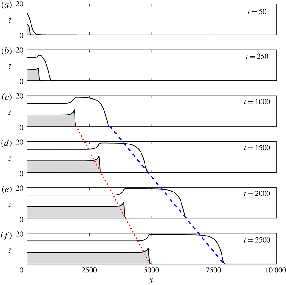

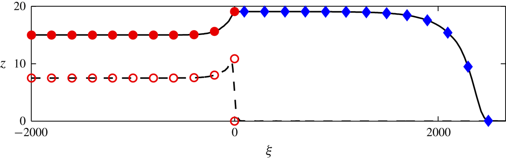


 Open access

