


1. Introduction and motivation
High-temperature superconductors (HTS) have been recognized for the past two decades as offering attractive new pathways for magnet development (Bruzzone, Fietz & Minervini Reference Bruzzone, Fietz and Minervini2018). Compared to low-temperature superconductors (LTS), HTS enable the design of magnets that operate at higher magnetic field, higher temperature, higher current density, or combinations of all three. Compared to copper, HTS (and LTS) offer the benefit of significantly reduced energy dissipation within the magnet, enabling continuous operation at higher magnetic field. Naturally, these attributes of HTS are opening new opportunities for applications that benefit from improved magnets (Haught et al. Reference Haught, Daley, Bakke and Marchionini2007; Fietz et al. Reference Fietz, Barth, Drotziger, Goldacker, Heller, Schlachter and Weiss2013; Whyte et al. Reference Whyte, Minervini, LaBombard, Marmar, Bromberg and Greenwald2016; Maingi et al. Reference Maingi, Lumsdaine, Allain, Chacon, Gourlay, Greenfield, Hughes, Humphreys, Izzo and McLean2019). Robust efforts are ongoing to deploy HTS technology towards large-bore high-field magnets for magnetic fusion energy applications (Sorbom et al. Reference Sorbom, Ball, Palmer, Mangiarotti, Sierchio, Bonoli, Kasten, Sutherland, Barnard and Haakonsen2015; Sykes et al. Reference Sykes, Costley, Windsor, Asunta, Brittles, Buxton, Chuyanov, Connor, Gryaznevich and Huang2018).
While worldwide focus has been largely directed towards high-field planar magnet systems, little attention has been paid to new opportunities enabled by HTS technology in applications that benefit from improved non-planar magnets. Non-planar configurations can be found in force-balanced (helical) coils for magnetic energy storage (Miura, Sakota & Shimada Reference Miura, Sakota and Shimada1994), particle accelerator magnets using saddle/bedstead (Thomas, Faircloth & Jago Reference Thomas, Faircloth and Jago2005) or canted cosine theta (Amemiya et al. Reference Amemiya, Miyahara, Ogitsu and Kurusu2015) geometries and the stellarator concept of a magnetic fusion energy system (Najmabadi & Raffray Reference Najmabadi and Raffray2006; Wolf Reference Wolf2008).
The unusual (essentially two-dimensional) form factor of HTS tape has given rise to several methods to convert such tape into a viable conductor. Integrated multi-tape conductor concepts include: interleaving HTS tapes into a Roebel assembly (Goldacker et al. Reference Goldacker, Frank, Heller, Schlachter, Ringsdorf, Weiss, Schmidt and Schuller2007), winding HTS tape helically along a cylindrical form (termed cable on round core conductor (Weiss et al. Reference Weiss, Mulder, Ten Kate and Van Der Laan2017)) and forming stacks of many HTS tape layers and winding the stack in various arrangements (termed twisted stacked-tape conductor (Takayasu et al. Reference Takayasu, Chiesa, Bromberg and Minervini2012)). However, the first and still the simplest method to construct a magnet from HTS tape is simply to wind the HTS tape in a ‘bare’ non-insulated and non-epoxy-impregnated configuration around a bobbin that defines the shape of the final coil. This type of coil is referred to as a non-insulated HTS (NI-HTS) coil (Hahn et al. Reference Hahn, Park, Bascuñán and Iwasa2011; Kim et al. Reference Kim, Hahn, Kim, Kwon and Lee2012).
1.1. Primer on benefits and drawbacks of NI-HTS magnets
A central benefit of the NI-HTS magnet is its simplicity. In this configuration the HTS tape is wound directly onto a shaped bobbin that defines the winding geometry, with the turns usually arranged in a double-pancake geometry. The desired magnet performance (in kiloamp turns, kAt) is then achieved by adding turns to each pancake, or deploying multiple double pancakes. These coils do not require (and indeed cannot allow) cooling channels within the conductor stack. Any heat generated must instead be rejected through the bobbin structure. Also, as the number of turns in the NI-HTS magnet is generally very large, a low supply current is required to drive them in steady state.
Beyond simplicity, owing to the absence of an insulator between turns, NI-HTS magnets offer a degree of intrinsic superconductivity quench protection. This is because the electrical current is offered a multitude of parallel paths to avoid any non-superconducting failure point (Kim et al. Reference Kim, Hahn, Kim, Kwon and Lee2012; Hahn et al. Reference Hahn, Radcliff, Kim, Kim, Hu, Kim, Abraimov and Jaroszynski2016) and significant headroom to the critical temperature for superconductivity generally exists. Indeed, NI-HTS quenches are observed to appear as soft limits, as opposed to hard destructive events (Brittles & Bateman Reference Brittles and Bateman2019). Despite these promising results, the quench dynamics of large-scale NI-HTS coils is still at the frontier of HTS magnet research.
Finally, as the HTS tape itself consists of superconducting layers deposited onto a steel substrate, winding an NI-HTS tape magnet on a steel bobbin results in a final assembly mechanically very similar to pure steel. This yields reduced differential thermal expansion issues and significantly enhanced strength as compared to other magnets.
Drawbacks can also be identified. Owing to the large number of turns of conductor ( $N$) required, NI-HTS coils are typically high in inductance ( $L \propto N^2$) and thus cannot quickly change current, with a less inductive path instead followed. These considerations challenge use of NI-HTS coils in alternating current or pulsed operating modes and favour deployment to truly steady-state applications, such as long-time-scale energy storage, particle accelerators and the stellarator fusion concept. Notably, NI-HTS would be challenging to use in the central solenoid and poloidal field coils of the tokamak fusion concept due to the time-varying current requirement, though the toroidal field coils are steady state.
The NI-HTS coil also suffers from a second drawback. For large-bore, high-field applications, the number of turns (and/or the number of double pancakes) required is very large, as is the path length of each turn. Either severely long lengths of HTS tape or a large number of resistive joints are thus required, creating a practical limitation to the ultimate potential of this magnet type. These drawbacks naturally drive large-scale development towards the complex multi-tape conductor assemblies as described earlier.
1.2. Compatibility of NI-HTS magnets with non-planar applications
Considering deployment of NI-HTS magnets to non-planar applications, two additional constraints arise. First, the radius of curvature along the winding trajectory no longer points towards a fixed point, but instead can take arbitrary form. This necessitates the introduction of hard-way bending strain and torsional bending strain. While nearly planar geometries like HTS tape easily tolerate out-of-plane (easy-way) bending (akin to folding paper) they do not tolerate in-plane (hard-way) bending (akin to stretching paper). Second, the magnetic field generated by the magnet is no longer predominantly parallel to the HTS tape plane (as it is in a planar magnet), but instead has significant transverse field components ( $B_{\perp }$). Both of these issues degrade the HTS tape performance and ultimately limit its operating space.
In this work a new winding angle optimization method is developed and presented to mitigate the aforementioned HTS tape compatibility issues of strain and transverse field. The winding angle is a free parameter for any fixed filamentary coil model, and will here be exploited as an optimization parameter to mitigate the issues associated with deploying NI-HTS coils in non-planar applications. Realizing a complex yet mechanically rigid bobbin with tracks at the optimized winding angle is enabled by additive manufacturing. Implicit in using the winding angle to optimize against engineering constraints is the assumption that it has minimal impact on the physics mission (via field errors). This assumption should be valid for the high current densities enabled by HTS technology, but if not additional constraints would be needed in the optimization here discussed. Note that these compatibility issues also generally apply to bending HTS multi-tape cable assemblies (Bykovsky et al. Reference Bykovsky, Uglietti, Wesche and Bruzzone2015). However, in a cable assembly the tape orientation is not available for optimization, unlike in the NI-HTS concept. This offers the opportunity to significantly increase the performance and geometric flexibility of a non-planar NI-HTS magnet as compared to HTS cable assemblies.
1.3. Goal, structure and summary of work
The goal of this paper is to discuss the compatibility of NI-HTS coils for non-planar applications (in particular the mid-scale stellarator), and to present a novel winding angle optimization method developed to overcome the identified limitations. For fixed input non-planar coil filamentary geometry, the winding angle is to first order a free parameter. The optimization method is described in § 2, and the candidate non-planar coil geometries examined (well-known stellarator designs) are described in § 3. Results of strain-only optimizations are presented in § 4. These optimizations are able to assess the minimum size of a non-planar coil that can be wound without exceeding strain limits for a given width of HTS tape, which are found to be between 0.3 and 0.5 m in mean coil radius for the studied stellarator configurations. Identifying the minimum size allows identification of a mid-scale stellarator capable of achieving high-field or high-temperature operation with minimal HTS tape length. Results of combined strain and  $B_{\perp }$ optimizations are presented in § 5. By defining coils larger than the minimum size, headroom is created to allow reduction of the $B_{\perp }$ component, enabling access to higher field for fixed HTS tape length, or the same field at reduced HTS tape length. Alternatively, strain-optimized larger coils permit the use of wider (higher current capacity) HTS tapes. The degree of benefit depends on the target coil size and geometry, as this method can quantify. Conclusions are presented in § 6. The appendix contains a discussion of how to optimize the stellarator coil geometry itself for improved compatibility with NI-HTS magnets, a topic that can open new opportunities in configuration design. As the magnetic fields used to confine stellarator plasmas arise predominantly from external coils, the geometry and specification of these coils define the stability and confinement of the plasma, oftentimes increasing coil complexity to achieve favourable plasma properties (Ku & Boozer Reference Ku and Boozer2010).
2. Winding angle optimization method
By calculating the peak strain due to hard-way bending ( $\epsilon _{\textrm {bend}}$) along with $B_{\perp }$ along the coil trajectory as a function of winding angle ( $\theta _{\textrm {wind}}$), a trajectory can be found that minimizes arbitrary cost functions of these two metrics. To minimize torsional strain ( $\epsilon _{\textrm {tor}}$) a tensioned spline fit to the optimal trajectory allows identification of the optimum trade-off between the cost function and $\epsilon _{\textrm {tor}}$. Each of these steps is now described in detail.
2.1. Strain considerations
Two strain components are possibly severe in non-planar coils made with NI-HTS tape, as illustrated in figure 1. These are the hard-way bending strain ( $\epsilon _{\textrm {bend}}$) and the torsional strain ( $\epsilon _{\textrm {tor}}$) (Takayasu, Minervini & Bromberg Reference Takayasu, Minervini and Bromberg2010).
Visualization of the strain components considered in the optimization. The hard-way bending strain ( $\epsilon _{\textrm {bend}}$, top left) is linearly proportional to the distance along the HTS tape width, while the torsional strain ( $\epsilon _{\textrm {tor}}$, bottom left) takes an offset-parabolic form. The peak strain ( $\epsilon _{\textrm {tot}}$) is simply found by summing these two components, and it is always found at one edge of the HTS tape.
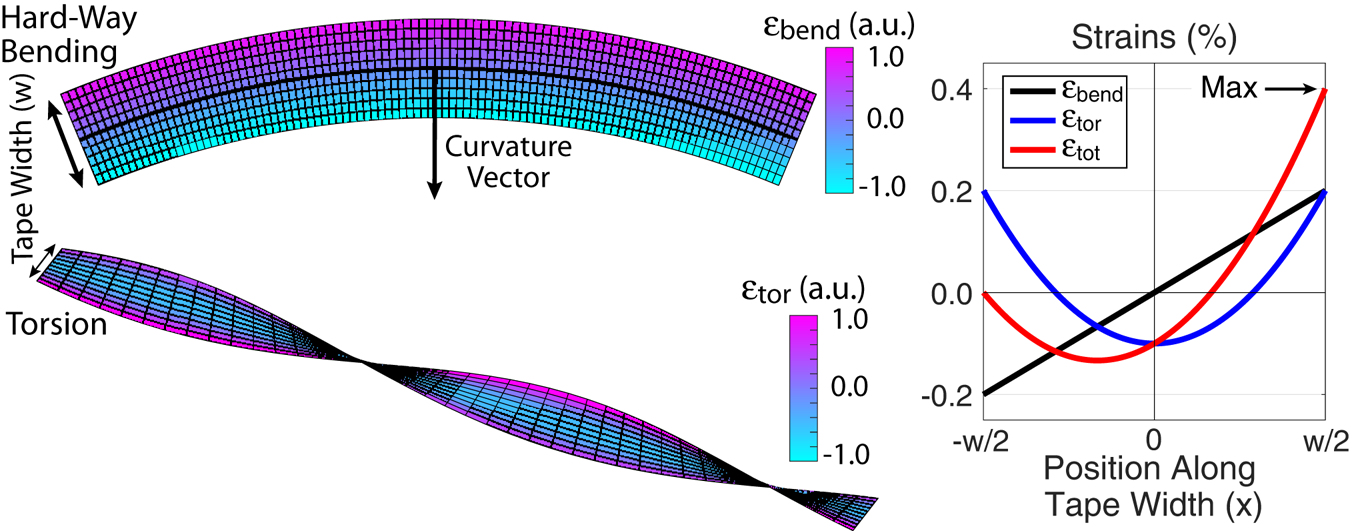
The hard-way bending strain is linearly proportional to the distance along the HTS tape width, and the magnitude depends on the radius of curvature via the following simple relationship:
 \begin{equation} \epsilon_{\textrm{bend}}(x) = \frac{x}{\left| r_{C} \right|}, \end{equation}
where  $r_{C}$ is the radius of curvature and $x$ is the position along the tape width $w$. It peaks at $x=w/2$, the tape edge, with a value of $\epsilon _{\textrm {bend}}=w/2|r_{C}|$. Here $r_{C}$ is calculated numerically using finite differences (Wang et al. Reference Wang, Arbelaez, Caspi, Prestemon, Sabbi and Shen2017), though if the coil trajectory is parametrized it can also be described analytically using the Frenet–Serret formulas (Gray, Abbena & Salamon Reference Gray, Abbena and Salamon2006).
Note the easy-way bending strain is also given by a similar relation, but it is smaller by the ratio of the tape width to its thickness. As normal HTS tape widths are 4, 6 and 12 mm while thicknesses are 0.1 mm, this strain component can be safely ignored. This also means that as long as the radius of curvature is directed along the major axis of the tape, a 40–120 times smaller radius of curvature can be tolerated. This can greatly impact optimization of the coil trajectory itself as will be discussed separately in the appendix. Note that easy-way strain is ignored in this study because it is so much lower than hard-way strain.
The torsional strain ( $\epsilon _{\textrm {tor}}$) does not depend on the local radius of curvature but instead is related to the angular rate of change of $r_{C}$ along the coil trajectory. The torsional strain takes the form (Takayasu et al. Reference Takayasu, Minervini and Bromberg2010)
 \begin{equation} \epsilon_{\textrm{tor}}(x) = \frac{1}{2}\left(\frac{\Delta \theta_{\textrm{wind}}}{\Delta L}\right)^2 \left(x^2-\frac{w^2}{12}\right) \end{equation}
for a position  $x$ along the tape width $w$, where $\Delta \theta$ is the angular rate of change of the winding angle $\theta _{\textrm {wind}}$ per unit length along the coil trajectory ( $\Delta L$). Here $\epsilon _{\textrm {tor}}$ takes an offset-parabolic form and also peaks at the tape edge ( $x={\pm }w/2$), with a value of $\epsilon _{\textrm {tor}}=(\Delta \theta _{\textrm {wind}} / \Delta L)^2 w^2/12$. Parameter $\Delta \theta _{\textrm {wind}}$ is also calculated numerically using finite differences, but it too can be described analytically using the Frenet–Serret formulas if the trajectory is parametrized.
A scalar metric representing the total strain ( $\equiv \epsilon _{\textrm {tot}}$) is now defined from $\epsilon _{\textrm {bend}}$ and $\epsilon _{\textrm {tor}}$. To rigorously treat the problem, the three-dimensional internal strains at every point in the tape should be taken into account using the principal strain method (Roark, Young & Plunkett Reference Roark, Young and Plunkett1976), including actual material properties such as the Poisson ratio, modulus of elasticity and modulus of rigidity to relate the different strain tensor elements. To simplify the problem and avoid sensitivity to material properties, a less rigorous but more conservative metric is used in this work – the maximum of a scalar sum of the $\epsilon _{\textrm {bend}}$ and $\epsilon _{\textrm {tor}}$ components:
 \begin{equation} \epsilon_{\textrm{tot}}=\max( \epsilon_{\textrm{bend}}(x)+\epsilon_{\textrm{tor}}(x)). \end{equation}
Note that the maximum  $\epsilon _{\textrm {tot}}$ always occurs at one tape edge or another ( $x={\pm }w/2$), based on the relative directions of $\epsilon _{\textrm {bend}}$ and $\epsilon _{\textrm {tor}}$. This method is conservative because it assumes the strain components are fully collinear (which is approximately true in the limit of thin tapes). Comparison of (2.3) and the principal strain method finds the strain can be overestimated by 15–20 % by (2.3). This overestimate is expected to be compensated by increases in the real material strain introduced by material imperfections, giving additional credence to this conservative approach.
In terms of a limit to the acceptable  $\epsilon _{\textrm {tot}}$, in principle empirical data should be gathered at the target operating strain and field conditions to validate the expected performance of the HTS tape. In the absence of such data this study uses an industry rule-of-thumb, which is that a maximum $\epsilon _{\textrm {tot}}$ limit of 0.4 % should be enforced (Allen, Chiesa & Takayasu Reference Allen, Chiesa and Takayasu2015; Takayasu & Chiesa Reference Takayasu and Chiesa2015). Above this limit there is a risk of reduction in the critical superconducting current $I_{\textrm {crit}}$ capacity as well as delamination of the internal layers within the HTS tape (Zhang et al. Reference Zhang, Hazelton, Kelley, Kasahara, Nakasaki, Sakamoto and Polyanskii2016). Regardless, the optimization framework can take arbitrary strain limits as input, and results are generally given in terms of peak predicted $\epsilon _{\textrm {tot}}$.
2.2. Transverse field considerations
Strain is the primary consideration in mid-scale coils as they can easily encounter limits with severe mechanical consequences. Notwithstanding this, the magnitude of the magnetic field transverse to the HTS tape plane ( $B_{\perp }$) is also an important consideration. Large $B_{\perp }$ imposes a soft limit on HTS tape performance as it degrades $I_{\textrm {crit}}$. Indeed, as progressively larger coils are considered, the most important factor can shift from strain to $B_{\perp }$, as strain issues are more easily avoided due to large size. Furthermore, larger coils can allow the use of HTS tapes narrower than the maximum allowable width, which would also emphasize $B_{\perp }$ over strain. For this study, data on this limitation are obtained from publicly available HTS tape manufacturer data (Superpower 2018).
Note that unlike the strains,  $B_{\perp }$ depends on coils throughout the entire configuration. As such, to compute $B_{\perp }$ the fields from all conductors in the configuration must be taken into account. This includes all other magnets as well as the fields from other turns within the magnet. A limitation of the present study is that a single-filament approximation for each magnet is taken, ignoring the finite coil winding pack size. This approximation will not materially affect $B_{\perp }$ arising from other magnets as long as their separation is large compared to the winding pack size. Since the contribution to $B_{\perp }$ from the other magnets is what can be optimized by changing $\theta _{\textrm {wind}}$, this approximation should also not materially impact the optimization results. The total magnitude of $B_{\perp }$ is, however, underestimated, as this is affected by the winding pack geometry (size and aspect ratio). A second limitation is that additional strain may also arise from the transverse load arising from the HTS tape current crossing $B_{\perp }$. Quantification of this requires specifying both material properties as well as the target operating field and is outside the scope of the present study. However, this load should be reduced by minimizing $B_{\perp }$ via $\theta _{\textrm {wind}}$ optimization. These limitations may be improved upon in the future.
2.3. Optimization philosophy and cost function definition
As the  $\epsilon _{\textrm {bend}}$ limit is a hard constraint on the HTS integrity, while $B_{\perp }$ is a softer limit, the optimization philosophy is thus to first ensure strain is within tolerable limits, and then within these limits to optimize against $B_{\perp }$ as a secondary constraint. Since $\epsilon _{\textrm {bend}}$ and $B_{\perp }$ are single-valued functions of the winding angle $\theta _{\textrm {wind}}$, they can be directly computed for all possible $\theta _{\textrm {wind}}$. In contrast, $\epsilon _{\textrm {tor}}$ depends on the gradient of the final $\theta _{\textrm {wind}}$ trajectory and is thus not known a priori. Calculated $\epsilon _{\textrm {bend}}$ and $B_{\perp }$ for all possible $\theta _{\textrm {wind}}$ are shown in figure 2(b) for a single point along an example coil trajectory (the coil geometries considered are described in § 3). As can be seen, $\epsilon _{\textrm {bend}}$ depends sensitively on the HTS tape width, while $B_{\perp }$ naturally depends on the coil current. As can also be seen, the optimal $\theta _{\textrm {wind}}$ to minimize $B_{\perp }$ and $\epsilon _{\textrm {bend}}$ are different. Aligning $\theta _{\textrm {wind}}$ to the local curvature ensures $\epsilon _{\textrm {bend}}=0$, noting that this can be achieved on either the bobbin effective outer diameter or inner diameter. $(a)$ Schematic illustration of an NI-HTS coil section and example orientations of the winding angle ( $\theta _{\textrm {wind}}$), the magnetic field direction including components parallel ( $B_{\|}$) and transverse ( $B_{\perp }$) to the HTS tape plane and the local radius of curvature. Note that $\theta _{\textrm {wind}}$ is defined relative to the coil geometric centre. For simplicity, only one pancake is shown though several may be defined within a single bobbin, forming multiple double-pancake patterns. $(b)$ Example evaluations of the hard-way bending strain ( $\epsilon _{\textrm {bend}}$) and transverse field ( $B_{\perp }$) as a function of $\theta _{\textrm {wind}}$, with minima of each occurring for different $\theta _{\textrm {wind}}$. Strain $\epsilon _{\textrm {bend}}$ depends on the HTS tape width while $B_{\perp }$ depends on the coil current. If $\theta _{\textrm {wind}}$ is aligned to the local curvature then $\epsilon _{\textrm {bend}}=0$. $(c)$ Construction of a cost function, (2.4), allowing $B_{\perp }$ to be reduced while maintaining $\epsilon _{\textrm {bend}}$ below an input tolerable strain floor $\epsilon _{0}$. Solutions exist on both the bobbin effective outer diameter (O.D.) and inner diameter (I.D.).

The method chosen to enable simultaneous optimization of  $\epsilon _{\textrm {bend}}$ and $B_{\perp }$ is to define a cost function that is a linear sum of $\epsilon _{\textrm {bend}}$ and $B_{\perp }$ with an ad hoc relative scale factor $\alpha$. The cost function is defined as
 \begin{equation} \left. \begin{gathered} \epsilon_{\textrm{bend}} + \alpha B_{\perp} \quad \text{if} \ \epsilon_{\textrm{bend}}> \epsilon_{0},\\ \epsilon_{0} + \alpha B_{\perp} \quad \text{if}\ \epsilon_{\textrm{bend}}< \epsilon_{0}. \end{gathered} \right\} \end{equation}
 The parameter  $\epsilon _{0}$ is the bending strain that is deemed to be tolerable and is an input free parameter. An essential feature of the cost function is that when $\epsilon _{\textrm {bend}}$ is below $\epsilon _{0}$ the cost function sees no variation arising from $\epsilon _{\textrm {bend}}$ and instead minimizes $B_{\perp }$. In this way, the cost function can accommodate smaller-size strain-constrained geometries as well as larger-size geometries where strain is less of an issue. Note that $\epsilon _{\textrm {tor}}$ is not included in the cost function, since it depends on the gradient of the $\theta _{\textrm {wind}}$ trajectory chosen (but not on $\theta _{\textrm {wind}}$ itself) and thus cannot be calculated a priori. Optimizing for $\epsilon _{\textrm {tor}}$ is discussed in the next section. An example cost function as applied to the same coil configuration is shown in figure 2(c). As can be seen, as long as the relative scale factor $\alpha \ll \max (B_{\perp })/\max (\epsilon _{\textrm {bend}})$, the $B_{\perp }$ term will only have an effect when $\epsilon _{\textrm {bend}} < \epsilon _{0}$, as desired. If $B_{\perp }$ considerations are ignorable, setting $\alpha =0$ results in a cost function equal to only $\epsilon _{\textrm {bend}}$.
2.4. Torsion optimization via tensioned splines
Definition of a cost function to optimize  $\theta _{\textrm {wind}}$ is not sufficient to solve the optimization problem, as the chosen $\theta _{\textrm {wind}}$ trajectory itself impacts the total strain via the torsional strain $\epsilon _{\textrm {tor}}$. This is because $\epsilon _{\textrm {tor}}$ is related to the rate of change of the chosen $\theta _{\textrm {wind}}$ (but not to $\theta _{\textrm {wind}}$ itself) along the trajectory. To address this problem, the approach is to compute the cost function (excluding $\epsilon _{\textrm {tor}}$) across all possible $\theta _{\textrm {wind}}$ at all positions along the coil trajectory, where it is well defined. This gives rise to contour plots of the cost function that visualizes the optimization problem, and provides a graphical method to reduce $\epsilon _{\textrm {tor}}$ while minimally increasing the cost function via the use of tensioned splines.
To simply illustrate this step of the optimization process a  $\epsilon _{\textrm {bend}}$-only cost function ( $\alpha =0$ in (2.4)) is used, and only a subset of the coil trajectory is shown in figure 3. As can be seen, the contours in figure 3(a) are simply $\epsilon _{\textrm {bend}}$ contours along the coil trajectory for all possible $\theta _{\textrm {wind}}$. The final $\theta _{\textrm {wind}}$ is fitted to the minimum of the cost function (the minimum of $\epsilon _{\textrm {bend}}$ in figure 3) using a tensioned spline approach. The magnitude of the local radius of curvature is used as a fitting weight for the tensioned spline, with low-curvature regions ascribed a low weight. Additionally, manual adjustment of the fit is possible by inserting points with high weighting to the fitting. This can drive the fit to find alternative optimal paths through the winding trajectory. Different fitted trajectories of $\theta _{\textrm {wind}}$ are indicated as the coloured lines in figure 3, with different tensions for each. For low spline tension, the fit closely matches the cost function minimum, while for high tension the variation of $\theta _{\textrm {wind}}$ along the coil trajectory is minimized. As can be seen in figure 3(b–d), this allows a direct trade-off between $\epsilon _{\textrm {bend}}$ and $\epsilon _{\textrm {tor}}$, and enables a minimum $\epsilon _{\textrm {tot}}$ ( $=\epsilon _{\textrm {bend}}+\epsilon _{\textrm {tor}}$) to be identified. Note that in some instances the optimal $\theta _{\textrm {wind}}$ trajectory includes regions where winding is primarily on the inner diameter of the coil ( $\theta _{\textrm {wind}} \approx 180^{\circ }$), as opposed to the outer diameter ( $\theta _{\textrm {wind}} \approx 0^{\circ }$).
Example use of spline tension to minimize total strain.  $(a)$ The cost function (here $\epsilon _{\textrm {bend}}$) is plotted for all winding angles ( $\theta _{\textrm {wind}}$) for a subset of an example coil trajectory. Varying the spline tension yields various possible $\theta _{\textrm {wind}}$ trajectories. (b–d) These different trajectories trade off $\epsilon _{\textrm {bend}}$ and $\epsilon _{\textrm {tor}}$ differently, giving rise to an optimum in the total strain ( $\epsilon _{\textrm {tot}}$).

While this method is surely not a unique solution to the optimization problem, the simple treatment is found to be sufficiently flexible to achieve the desired reduction in  $B_{\perp }$ within allowable $\epsilon _{\textrm {bend}}$ constraints.
At this point a key difference between this method and the method of calculating space-preserving maps (Gray et al. Reference Gray, Abbena and Salamon2006), giving rise to developable surfaces (also called the constant-perimeter method), should be clarified. As a result of the tensioned spline method utilized here, the optimal winding angle  $\theta _{\textrm {wind}}$ does not necessarily follow the radius of curvature. As such, the final tape surface is not an area-preserving map, and indeed this is why finite $\epsilon _{\textrm {bend}}$ is present. Were an area-preserving map method utilized, the resultant trajectory would likely undergo severe $\epsilon _{\textrm {tor}}$ as a result of its inability to trade off $\epsilon _{\textrm {tor}}$ with $\epsilon _{\textrm {bend}}$, as is done here. Also to be noted is that the optimization workflow also can treat a planar coil, in which case the optimal $\theta _{\textrm {wind}}$ returns zero throughout as expected.
3. Stellarator coil configurations considered
Though the optimization methods described in § 2 are applicable to arbitrary coil geometry, well-known yet complex coilsets from the stellarator are used as examples for winding angle optimization with these fixed input filamentary coil geometries. The configurations studied are the Helically Symmetric Experiment (HSX) (Anderson et al. Reference Anderson, Almagri, Anderson, Matthews, Talmadge and Shohet1995), the Wendelstein 7-X (W7-X) stellarator (Beidler et al. Reference Beidler, Grieger, Herrnegger, Harmeyer, Kisslinger, Lotz, Maassberg, Merkel, Nuehrenberg and Rau1990; Klinger et al. Reference Klinger, Baylard, Beidler, Boscary, Bosch, Dinklage, Hartmann, Helander, Maßberg and Peacock2013) and the National Compact Stellarator Experiment (NCSX) (Zarnstorff et al. Reference Zarnstorff, Berry, Brooks, Fredrickson, Fu, Hirshman, Hudson, Ku, Lazarus and Mikkelsen2001; Chrzanowski et al. Reference Chrzanowski, Meighan, Raftopoulos, Fogarty, Heitzenroeder, Nelson and Williamson2007). Each coilset was generated primarily based on varying constraints arising from plasma physics, alongside engineering constraints from the coilsets. Note that each configuration differs in physical size and magnet technology (HSX and NCSX are copper while W7-X is LTS). These coils, along with identifying coil numbers assigned for the purpose of this study, are shown in figure 4. Note that figure 3 used the no. 3 coil of the HSX configuration.
Stellarator geometries considered in this study. Non-planar coils in these configurations span from weakly to strongly non-planar.

In order to assess sensitivity to coil size and to estimate the minimum buildable coil size, a uniform geometric scale factor was applied to each of the stellarator configurations shown in figure 4. The average coil radius ( $\left \langle r_{\textrm {coil}}\right \rangle$) for each of these designs is plotted against the size scale factor applied in figure 5. Here $\left \langle r_{\textrm {coil}}\right \rangle$ is defined as the mean distance from the filamentary coil trajectory to the coil geometric centre. The coil geometric centre is in turn defined as the mean position of the coil trajectory.
Mean coil radius ( $\left \langle r_{\textrm {coil}}\right \rangle$) for each of the stellarator geometries considered as a function of the size scale factor applied. Size scale factor of 1.0 is the size of the as-built coil.
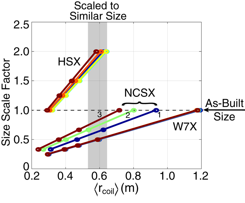
As can be seen, in terms of  $\left \langle r_{\textrm {coil}}\right \rangle$, W7-X is the largest though NCSX is only modestly smaller. However, as can be seen in figure 4, the complexity of the NCSX coils is considerably increased due to the more stringent constraints utilized in optimization (in particular the desire for a tight aspect ratio). The HSX coils are smallest and also the most simple. All devices were scaled such that they occupied an overlapping $\left \langle r_{\textrm {coil}}\right \rangle$ range between 0.2 and 0.6 m, with $\left \langle r_{\textrm {coil}}\right \rangle$ used hereafter to parametrize the coil size.
4. Strain optimization and minimum coil size
The main objectives of optimizations involving only strain are to provide headroom to further reduce  $B_{\perp }$ and to enable the use of progressively wider HTS tape widths (thus increasing the current capacity per turn). Strain-only optimizations also provide a means of determining the minimum buildable size of an NI-HTS coil at fixed tape width regardless of target $B_{\perp }$ or alternatively the maximum allowable HTS tape width at fixed size. As described in § 2.1, a value of 0.4 % is considered engineering best practice and is here used as the target allowable $\epsilon _{\textrm {tot}}$. Results are conveyed by plotting the peak strain ( $\epsilon _{\textrm {tot}}$) versus coil size ( $\left \langle r_{\textrm {coil}}\right \rangle$), in case further HTS advances modify the allowable strain.
The full coil trajectory for the no. 3 HSX coil shown in figure 4 (and highlighted in figure 3) is shown in figure 6. For this coil, some regions of the coil trajectory are very strongly constrained by  $\epsilon _{\textrm {bend}}$ while others are not. The tensioned spline approach allows quick identification of the optimal $\theta _{\textrm {wind}}$ trajectory.
The same  $\theta _{\textrm {wind}}$ trajectories of figure 3 now displayed for the entire HSX no. 3 coil trajectory. Again varying the spline tension yields $(a)$ various candidate $\theta _{\textrm {wind}}$ trajectories. (b–d) These different trajectories trade off $\epsilon _{\textrm {bend}}$ and $\epsilon _{\textrm {tor}}$ differently, giving rise to an optimum in the total strain ( $\epsilon _{\textrm {tot}}$).
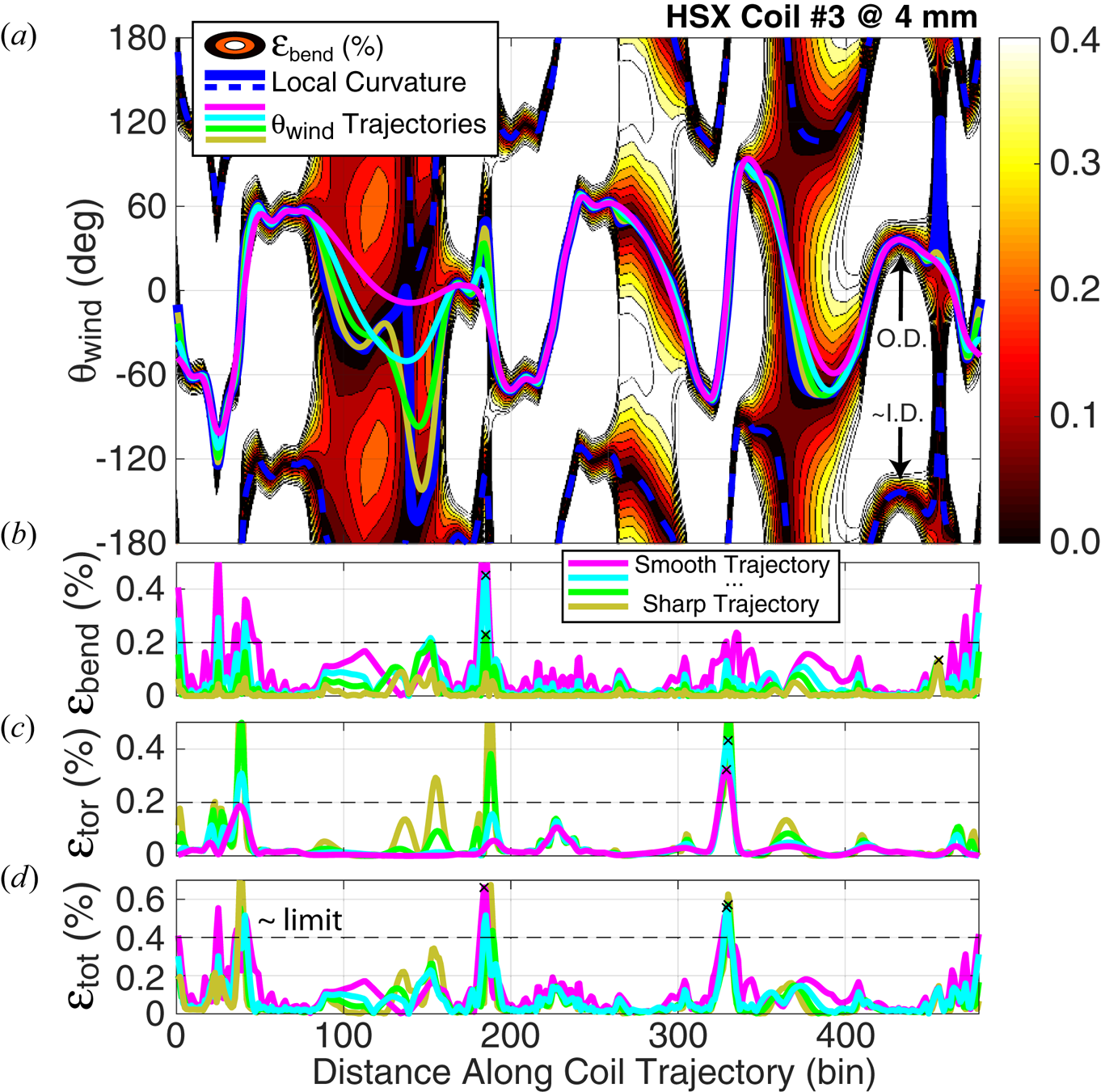
Figure 7 presents a graphical assessment of the  $\theta _{\textrm {wind}}$ optimization results and uses the colour axis to highlight the regions where the strain is most severe. As can be seen, the weak points are in the transition between bends, where some amount of $\epsilon _{\textrm {bend}}$ and $\epsilon _{\textrm {tor}}$ is unavoidable. Comparing figures 6 and 7, these occur around bins 35, 190 and 330. The winding angle (pink vector in figure 7) changes by a significant amount at these points, yet there is still a finite bend radius.
Three viewing angles of HSX coil no. 3 showing the local radius of curvature (blue vectors) and optimal  $\theta _{\textrm {wind}}$ trajectory (magenta vectors) for a strain-only optimization. Colours along the coil trajectory indicate relative $\epsilon _{\textrm {tot}}$. Regions of high $\epsilon _{\textrm {tot}}$ are found at the transition between bends.

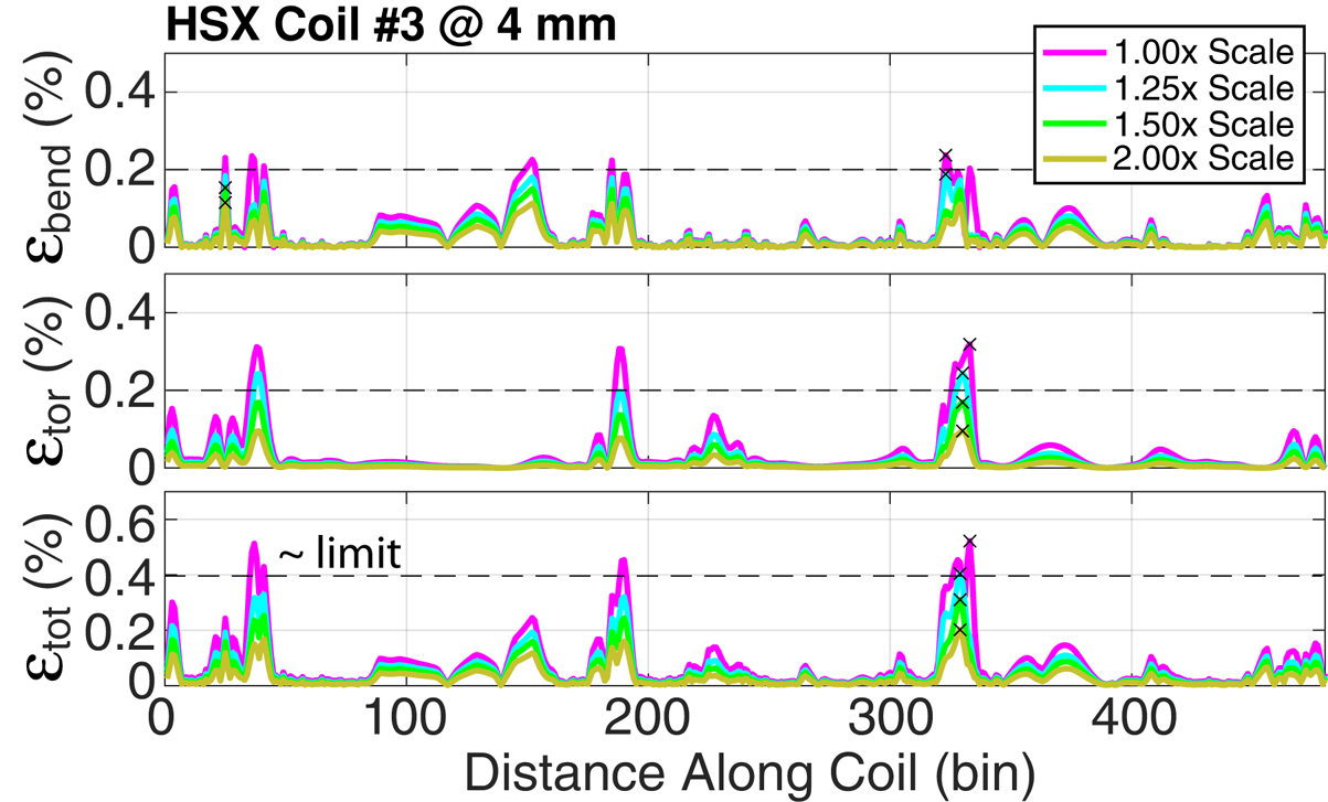
The impact of size scale factor on  $\epsilon _{\textrm {bend}}$, $\epsilon _{\textrm {tor}}$ and $\epsilon _{\textrm {tot}}$ is shown in figure 8, again using HSX coil no. 3. For each size scale factor, optimization including possible manual intervention as described in § 2.4 has been undertaken. Despite optimization, it is found that the 1.0 $\times$ size (as-built) coil exceeds the target strain of 0.4 %. As such, the as-built HSX is found to be too small to be compatible with the NI-HTS strain limits as here assumed. Increasing the size scale factor naturally reduces the strain, and already by 1.50 $\times$ scale factor the strain is below the assumed limit.
Variation of the strain components as a function of size scale factor for HSX coil no. 3. For each size scale factor the trajectory is optimized as in figure 6. The maximum  $\epsilon _{\textrm {tot}}$ ( $\times$ symbols) naturally decreases with size.
Using the same methodology, strain assessment as a function of coil size ( $\left \langle r_{\textrm {coil}}\right \rangle$) was conducted for all coils of the HSX, W7-X and NCSX stellarators. Results are presented in figure 9. As coil size decreases, the target total strain is exceeded, thus defining the minimum buildable $\left \langle r_{\textrm {coil}}\right \rangle$ for these existing configurations. Generally, a minimum $\left \langle r_{\textrm {coil}}\right \rangle$ of 0.3–0.5 m is found, though variations between coils and configurations exist.
(a–c) Peak total strain ( $\epsilon _{\textrm {tot}}$) and (d–f) peak bending ( $\epsilon _{\textrm {bend}}$) and torsion ( $\epsilon _{\textrm {tor}}$) strain for the stellarator configurations as a function of average coil size ( $\left \langle r_{\textrm {coil}}\right \rangle$) for 4 mm wide tape. As $\left \langle r_{\textrm {coil}}\right \rangle$ decreases, the target $\epsilon _{\textrm {tot}}$ is exceeded, thus defining the minimum $\left \langle r_{\textrm {coil}}\right \rangle$. Each colour indicates a specific coil, with inset coil images as presented in figure 4 included for reference.
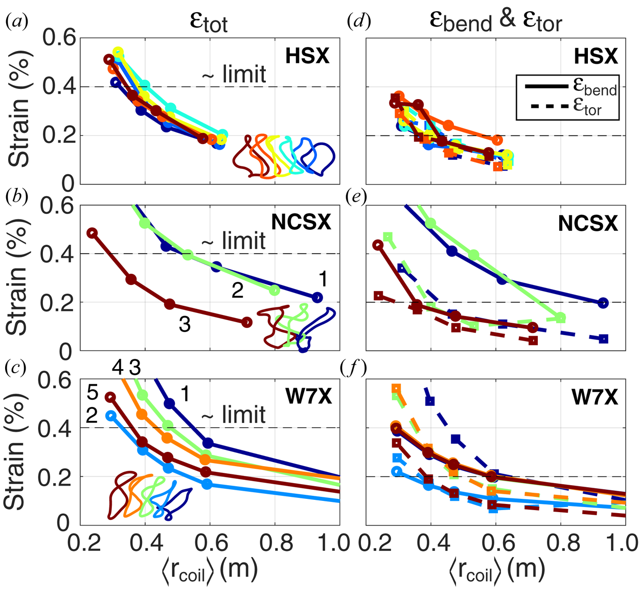
Note that HSX coil no. 3 is highlighted because it is most severely limited by strain, despite the fact that it is not the most non-planar. This implies that the degree of non-planar complexity is not directly related to the strain limits encountered, and further suggests optimization of the coil trajectory itself has the potential to significantly improve compatibility with NI-HTS coils. This is further discussed in the appendix.
5. Combined strain and transverse field optimization
Optimizations considering cost functions involving both strain ( $\epsilon _{\textrm {bend}}$, defined in § 2.1) and transverse field ( $B_{\perp }$, defined in § 2.2) using cost functions defined in § 2.3 are nowpresented. Coils optimized for both considerations must be larger than the minimum coil size ( $\left \langle r_{\textrm {coil}}\right \rangle$) shown in figure 9, as headroom in strain is needed to trade off against other factors (like $B_{\perp }$). As such, $B_{\perp }$ optimization becomes more important as the coil size increases. Furthermore, a design decision needs to be taken that the headroom in strain will be used to mitigate $B_{\perp }$ as opposed to increasing HTS current capacity by increasing the tape width. Recall that to compute $B_{\perp }$ the magnetic fields from all the coils comprising the configuration must be taken into account.
Strain-only (magenta) and combined strain +  $B_{\perp }$ (cyan) optimizations are demonstrated for coil no. 1 of the W7-X stellarator configuration, with optimized trajectories shown in figure 10. For this larger coil the larger radii of curvatures yield $\epsilon _{\textrm {bend}}$ contours that are significantly lower (figure 10b), enabling deviation of $\theta _{\textrm {wind}}$ from the $\epsilon _{\textrm {bend}}$ minimum. Contours of $B_{\perp }$ (figure 10c) show a different dependency on $\theta _{\textrm {wind}}$. The combined optimization (cyan lines) follows the cost function target (green) very closely, essentially overlaying. For the combined optimization, $\epsilon _{\textrm {tot}}$ now takes a finite value for most of the trajectory (figure 10a), very close to the input $\epsilon _{0}$ in (2.4) value of 0.2 %. The $B_{\perp }$ value was also meaningfully reduced by this method, by nearly 50 %.
Comparison of strain-only (magenta) and combined strain +  $B_{\perp }$ (cyan) optimization for W7-X coil no. 1. Evaluations of $(a)$
$(a)$  $\epsilon _{\textrm {tot}}$, $(b)$
$(b)$  $\epsilon _{\textrm {bend}}$ versus $\theta _{\textrm {wind}}$, $(c)$
$(c)$  $B_{\perp }$ and $(d)$
$(d)$  $B_{\perp }$ versus $\theta _{\textrm {wind}}$. Allowing finite $\epsilon _{\textrm {tot}}$ enables a significant reduction of $B_{\perp }$ along the optimal $\theta _{\textrm {wind}}$ trajectory.

At this point it should be mentioned that some coils (such as the one highlighted in figure 10) contain apparent artefacts in the coil trajectory that inhibit compatibility with NI-HTS. This can be seen in the wiggles in the local curvature (blue line) in figure 10(b) around bin 210. As size scale factor is reduced, this feature imposes a high strain and limits the buildable size. As can be seen in figure 11, this artefact occurs at the nominally straight section of the coil. While seemingly straight, these sectors are found to contain finite curvature (and finite  $\epsilon _{\textrm {bend}}$) requiring significant torsion ( $\epsilon _{\textrm {tor}}$) to mitigate. Improved coil trajectory definition should avoid these artefacts as is described in the appendix.
Two viewing angles of W7-X coil no. 1 including the local radius of curvature (blue vectors) and optimal  $\theta _{\textrm {wind}}$ trajectory (magenta vectors) for a strain-only optimization. Colours along the coil trajectory indicate relative $\epsilon _{\textrm {tot}}$. Regions of high $\epsilon _{\textrm {tot}}$ are found at the straight section, indicating an artificial constraint is present.

Using publicly available data on the achievable  $I_{\textrm {crit}}$ for a given HTS tape width at various $B_{\perp }$ and operating temperature conditions (Superpower 2018), the HTS tape length needed for a given $B_{\textrm {axis}}$ can be estimated. This is shown in figure 12 for the same trajectories of figure 10 using W7-X coil no. 1. The reduction in $B_{\perp }$ enables a meaningful increase in the achievable $B_{\textrm {axis}}$ for fixed tape width ( $L_{\textrm {tape}}$) or alternatively a reduction in $L_{\textrm {tape}}$ for a fixed $B_{\textrm {axis}}$. $(a)$ Transverse field ( $B_{\perp }$), $(b)$ critical current ( $I_{\textrm {crit}}$) and $(c)$ required HTS tape length as a function of $B_{\textrm {axis}}$ for W7-X coil no. 1.

A second example is provided using the same HSX coil no. 3 described in detail in § 4. However, since the 1 $\times$ size scale factor was already above the target strain limit, a 2 $\times$ size scale factor is used. This provides the necessary headroom to, in principle, optimize against both strain and $B_{\perp }$. However, as shown in figure 13, allowing finite strain does not significantly improve optimization performance, with peak $B_{\perp }$ nearly unchanged. Looking in detail at the constrained region in figure 13(e), $\epsilon _{\textrm {bend}}$ is found to be below $\epsilon _{0}$ only in a small region of $\theta _{\textrm {wind}}$. Within this allowable $\theta _{\textrm {wind}}$ region, no significant $B_{\perp }$ reduction can be achieved. Thus, this particular coil is resistant to further optimization.
Comparison of strain-only (magenta) and combined strain +  $B_{\perp }$ (cyan) optimization for HSX coil no. 3 at 2 $\times$ size scale factor. Evaluations of $(a)$
$(a)$  $\epsilon _{\textrm {tot}}$, $(b)$
$(b)$  $\epsilon _{\textrm {bend}}$ versus $\theta _{\textrm {wind}}$, $(c)$
$(c)$  $B_{\perp }$ and $(d)$
$(d)$  $B_{\perp }$ versus $\theta _{\textrm {wind}}$. Allowing finite $\epsilon _{\textrm {tot}}$ is not found to improve this optimization by a significant degree, due to $(e)$ a poor alignment of $B_{\perp }$ and $\epsilon _{\textrm {bend}}$ constraints around bin 69.

Mapping of the  $I_{\textrm {crit}}$ data to this coil as $B_{\textrm {axis}}$ is scaled is shown in figure 14 for HSX coil no. 3 at 2 $\times$ size scale factor. As $B_{\perp }$ did not much change when included in the optimization, both strain only and combined yield similar results. Note that due to the small size, a fairly low $L_{\textrm {tape}}$ is sufficient to access high $B_{\textrm {axis}}$, revealing a cost-effective path to accessing high- $B_{\textrm {axis}}$ physics at mid-scale enabled by strain optimization. $(a)$ Transverse field ( $B_{\perp }$), $(b)$ critical current ( $I_{\textrm {crit}}$) and $(c)$ required HTS tape length as a function of $B_{\textrm {axis}}$ for HSX coil no. 3 at 2 $\times$ size scale factor. Combined strain + $B_{\perp }$ optimization did not improve the required $L_{\textrm {tape}}$ in this case.

Combined optimization of all the coils in the HSX configuration at 2 $\times$ size scale factor is performed and results are given in figure 15. For many coils, the $B_{\perp }$ component could be meaningfully reduced, especially for the least planar coils (nos. 1 and 2). As discussed, coil no. 3 was barely affected, and the other most planar coils less so. Nonetheless, at least in some instances the increased allowance for strain enables a significant reduction in the needed $L_{\textrm {tape}}$. Final adjudication between all optimization constraints requires a target $B_{\textrm {axis}}$ as well as a notional budget, as increasing $L_{\textrm {tape}}$ implies an increased cost penalty.
Summary of performance improvement via combined strain +  $B_{\perp }$ optimization for all HSX coils at 2 $\times$ size scale factor. The least planar coils ( nos. 1 and 2) obtain a meaningful benefit while the more planar coils are fairly constrained and do not benefit as much. In both optimizations, $L_{\textrm {tape}}$ of a few kilometres gives access to $B_{\textrm {axis}}$ of several teslas.

6. Discussion and conclusions
This work has presented the benefits and drawbacks of NI-HTS magnet technology specifically for its application to non-planar coils. To first order, for a fixed input non-planar coil filamentary geometry, the winding angle ( $\theta _{\textrm {wind}}$) is an unspecified free parameter. A novel winding angle optimization method is here introduced to optimize compatibility with the NI-HTS concept by mitigating the drawbacks of increased hard-way bending strain ( $\epsilon _{\textrm {bend}}$), torsional strain ( $\epsilon _{\textrm {tor}}$) and increased transverse field ( $B_{\perp }$). By trading off the two strains against each other via an optimized $\theta _{\textrm {wind}}$ trajectory, a minimum peak total strain and a reduced $B_{\perp }$ can be obtained. This minimum peak total strain in turn enables assessment of the minimum buildable size for a given input non-planar coil geometry. For well-known existing stellarator designs, the minimum mean coil radius was found to be 0.3–0.5 m for 4 mm wide HTS tape. Identifying the minimum size provides a path to specify a mid-scale stellarator capable of achieving high-field or high-temperature operation with minimal HTS tape length.
For coils larger than this minimum size, the total strain ( $\epsilon _{\textrm {tot}}$) can be traded off against $B_{\perp }$ to reduce this component. This enables a reduction of the length of HTS tape required to achieve a given design magnetic field or equivalently an increase in the achievable magnetic field for constant HTS tape length. Alternatively, optimizing $\theta _{\textrm {wind}}$ for a larger size coil would permit the use of wider HTS tapes, thereby increasing the current-carrying capability of each turn and/or winding, thus reducing the number required to achieve the design magnetic field.
Acknowledgements
This work was supported by General Atomics Internal Funds. The author would like to thank A. Benson, B. Breneman, J. Leuer, J. Smith, Z. B. Piec and L. Holland for useful discussions. The author also thanks S. Lazerson and A. Bader for the provision of the existing stellarator device coil geometry information.
Editor Cary Forest thanks the referees for their advice in evaluating this article.
Declaration of interests
The authors report no conflict of interest.
Appendix. Optimization of the coil trajectory for stellarator applications
This work has focused on optimizing the winding angle optimization of a predefined coil to maximize compatibility with NI-HTS magnet technology. Considerations for optimizing the coil trajectory itself now are briefly summarized. This discussion focuses on stellarator applications, as there are many possible degrees of freedom in the coil geometry of these concepts and significant coil optimization work already exists in this area (Merkel Reference Merkel1987; Pomphrey et al. Reference Pomphrey, Berry, Boozer, Brooks, Hatcher, Hirshman, Ku, Miner, Mynick and Reiersen2001; Strickler, Berry & Hirshman Reference Strickler, Berry and Hirshman2002; Landreman Reference Landreman2017; Paul et al. Reference Paul, Landreman, Bader and Dorland2018; Zhu et al. Reference Zhu, Hudson, Song and Wan2018a,Reference Zhu, Hudson, Song and Wanb).
Stellarator coil optimizations are done with many constraints in mind, most having to do with plasma physics. Considering the constraints arising from the coil technology itself, two constraints are usually included: curvature and coil–coil distance. Interestingly, NI-HTS magnets pose significantly different constraints from those conventionally considered.
First, considering curvature, for an NI-HTS magnet, strain arising from regular curvature is negligible, and is also called ‘easy-way’ bending. The strain issues discussed in § 4 are important, and in particular the interplay of torsion and hard-way bending. If curvature is weakly penalized, yet torsion is not, very different stellarator coil shapes may arise from optimizations against these alternative criteria, particularly with more pronounced toroidal joggles.
Second, considering coil–coil spacing, the compactness (high current density) and mechanical strength (steel substrate and bobbin) inherent to the NI-HTS magnet have the potential to support significantly reduced coil–coil spacing. The final spacing depends on the amount of bobbin material required, which arises from the electromagnetic forces, which require definition of the target operating magnetic field. However, at least as compared to copper and LTS, significantly smaller coil–coil separations can be anticipated.
Finally, stellarator coils are usually parametrized via Fourier series. As for example in the W7-X coil of figure 11, this gives rise to an artefact in the straight sections of the coil where residual undulations exist from incomplete cancellation of the Fourier series. These residual undulations severely compromise compatibility with NI-HTS, despite their origin from a mostly straight section of the coil. Using tensioned splines to parametrize the coil trajectory should remove this artificial limitation.
While outside the scope of this activity, stellarator coil optimizations using these alternative criteria are thus highlighted as fertile ground for future study.


