


Introduction
In structural material design and especially when user's lives are at risk, safety and durability are paramount [Reference Ashby1]. For this reason, tough materials, such as metals, have historically been used in safety critical applications. Tough materials will deform plastically before breaking, whereas brittle materials will break catastrophically [Reference Callister2]. High toughness comes primarily from the presence of energy dissipation mechanisms acting to delay a crack growth. Most dissipation mechanisms arise directly from the defects and the chemical bonds present in the atomic structure. Metals plastically deform using dislocation movements or twinning. In ceramics, the high energy and directionality of the iono-covalent bonds between the atoms block the movement of dislocations and they fail in a brittle manner. However, the energetic bonds in ceramics bring also their best features: they are temperature and chemical resistant, hard, and stiff [Reference Callister2]. All these features make them perfectly suited to work in demanding environments: in the high temperature reached in plane engines or next-generation nuclear fusion reactor [Reference Krenkel3], inside the human body as implants to replace hip, knee, and teeth [Reference Chevalier and Gremillard4], even in our pockets for transparent and scratch-resistant smartphone screens [Reference Varshneya5]. One way to mitigate ceramic brittleness and make them safe to use for these applications is to program, inside the microstructure this time, mechanisms that will delay a crack growth [Reference Becher6, Reference Evans7]. The microstructure, not the atomic structure, dictates what mechanisms are available and how effective they are.
Ceramics, as the flagship brittle materials, have been the centre of focus on toughness improvements [Reference Evans7]. One of the first solution found was to copy the architecture of long fibre polymer matrix composite and use only ceramic components. In ceramic matrix composites (CMCs) [Reference Krenkel3], cracks are delayed by strong fibres that bridge the crack first and then provide pull-out mechanisms once broken [Reference Evans8]. These mechanisms are potent enough to reach up to 1% plastic strains for in-plane woven architecture but at the cost of long and complex fabrication processes [Reference Hillig9]. After 40 years of development, CMCs are so tough and heat resistant that they are used in civil plane engines now [Reference Padture10]. From this research stemmed a body of work on short fibres and elongated grain ceramics that are simpler to process and also provide some toughening mechanisms [Reference Becher6, Reference Becher, Sun, Plucknett, Alexander, Hsueh, Lin, Waters and Westmoreland11, Reference Cao, Moberlychan, De Jonghe, Gilbert and Ritchie12, Reference Belmonte, Moya, Miranzo, Nguyen, Dubois and Fantozzi13]. The most studied example is the one of silicon nitride, once looked after to build ceramic car engines [Reference Becher6, Reference Becher, Sun, Plucknett, Alexander, Hsueh, Lin, Waters and Westmoreland11]. Then came the discovery of transformation toughening in zirconia-based ceramics [Reference Garvie, Hannink and Pascoe14]. Zirconia present a phase transformation from tetragonal to monoclinic that also triggers a 4% volume increase [Reference Wang and Stevens15, Reference Chevalier, Deville, Fantozzi, Bartolomé, Pecharroman, Moya, Diaz and Torrecillas16]. If the zirconia tetragonal is stabilized down to room temperature using dopants, then this volume increase can be used to block crack from propagating [Reference Evans and Heuer17, Reference Hanninck, Kelly and Muddle18]. In the most recent work, some researchers managed to get to toughness of 10 MPa m1/2 and strength of 570 MPa with a strain at failure of almost 0.6% [Reference Touaiher, Saâdaoui, Chevalier, Preiss and Reveron19].
A more recent approach has been to use natural structures as blueprint to make tougher, stronger, and more lightweight composites [Reference Huang, Restrepo, Jung, Su, Liu, Ritchie, McKittrick, Zavattieri and Kisailus20, Reference Wegst, Bai, Saiz, Tomsia and Ritchie21]. Through millions of years of evolution, natural materials evolved as intricate and hierarchical structures that solved the same problem we are now facing. One of such delicate structure is natural nacre, also called mother of pearl, a constituent of mollusc's shells. It is one of the toughest, strongest, and stiffest natural material studied so far, and it is made of 95 vol% CaCO3 and 5 vol% of protein [Reference Espinosa, Rim, Barthelat and Buehler22]. All the research on nacre was triggered by the study of Currey et al. [Reference Currey and Taylor23, Reference Currey24]. The researchers measured the mechanical properties of nacre in tension and observed that despite being made of 95 vol% of brittle aragonite, nacre bends instead of breaking, reaching 1–2% strain with a yield stress around 60–100 MPa [Fig. 1(a)] [Reference Currey24]. At first glance, the microstructure resembles a brick and mortar structure, with bricks of 7 µm in diameter and 500 nm in thickness perfectly stacked together [Fig. 1(b)]. On closer observation of the interface between the bricks, it appears that the protein forms a film a few nanometres thick, whereas the bricks present a rough surface, with 5–10% of the area bridged by mineral nanoparticles [Reference Meyers, Lin, Chen and Muyco25, Reference Song, Soh and Bai26]. The bricks also present a surface waviness that could promote interlocking during failure [Reference Barthelat, Tang, Zavattieri, Li and Espinosa27]. During failure, instead of having a crack growing, the microstructure adapts, and a collective movement of the bricks is observed [Fig. 1(c)], allowing a macroscopic deformation. This was observed by Currey et al. already with the report of “white bands” appearing upon deformation [Reference Currey24]. This triggered a wave of research to try and obtain the same behavior, or at least toughness value for composite higher than the ones of the individual constituents.
Mechanical properties and microstructure of natural nacre. (a) Stress–strain curve of nacre in bending compared with an aragonite crystal. (b) Scanning Electron Microscope image of nacre. (c) SEM image of nacre showing the collective platelets movement under tensile stresses. (a) and (c) adapted from Ref. Reference Barthelat, Tang, Zavattieri, Li and Espinosa27. (with permission from Elsevier.) (b) SEM Nacre: Dr. Tobias P. Niebel.

An extended body of work can now be found on both processes and materials to make nacre-inspired composite [Reference Corni, Harvey, Wharton, Stokes, Walsh and Wood28]. Ice templating [Reference Mao, Gao, Yao, Liu, Colfen, Liu, Chen, Li, Yan, Liu and Yu29, Reference Deville, Saiz, Nalla and Tomsia30], laser engraving [Reference Valashani and Barthelat31, Reference Yin, Hannard and Barthelat32], heat-assisted slip casting [Reference Gurbuz and Dericioglu33], spray forming [Reference Dwivedi, Flynn, Resnick, Sampath and Gouldstone34], coextrusion [Reference Wilkerson, Gludovatz, Watts, Tomsia, Hilmas and Ritchie35], sedimentation [Reference Behr, Vainio, Müller, Schreyer and Schneider36], or lamination [Reference Clegg, Kendall, Alford, Button and Birchall37] has been used to produce brick and mortar structures at the hundreds to tens of micron scale with alumina [Reference Deville, Saiz, Nalla and Tomsia30], silicon carbides [Reference Naglieri, Bale, Gludovatz, Tomsia and Ritchie38], or hydroxyapatite [Reference Bai, Walsh, Gludovatz, Delattre, Huang, Chen, Tomsia and Ritchie39], whereas another branch focused on using 2D materials and paper-making process [Reference Morits, Verho, Sorvari, Liljeström, Kostiainen, Gröschel and Ikkala40, Reference Bonderer, Studart and Gauckler41, Reference Walther, Bjurhager, Malho, Pere, Ruokolainen, Berglund and Ikkala42, Reference Cheng, Huang, Peng, Wan, Du, Dou, Wagner, Tomsia and Jiang43, Reference Zhu, Jasinski, Benitez, Noack, Park, Goldmann, Barner-Kowollik and Walther44]. Because of Griffith scaling law, smaller reinforcement sizes usually mean stronger composites, so the next development was to use micron-sized bricks, with alumina platelets [Reference Hunger, Donius and Wegst45, Reference Bouville, Maire, Meille, Van de Moortèle, Stevenson and Deville46, Reference Du, Mao, Yu, Hou, Zhao, Han, Zhao, Gao, Xie and Bai47], glass flakes [Reference Gurbuz and Dericioglu33, Reference Magrini, Bouville, Lauria, Le Ferrand, Niebel and Studart48], or brushite platelets [Reference Gao, Chen, Mao, Song, Yao, Cölfen, Luo, Zhang, Pan, Meng, Ni and Yu49]. Several secondary phases have been used in these composites, from polymers [Reference Du, Mao, Yu, Hou, Zhao, Han, Zhao, Gao, Xie and Bai47, Reference Niebel, Bouville, Kokkinis and Studart50, Reference Askarinejad and Rahbar51] to metal [Reference Le Ferrand, Bouville, Niebel and Studart52, Reference Huang, Rubink, Lide, Scharf, Banerjee and Minary-Jolandan53, Reference Huang, Daryadel and Minary-Jolandan54, Reference Garnier and Dunand55, Reference Wat, Ferraro, Deng, Sweet, Tomsia, Saiz and Ritchie56] and even graphene [Reference Picot, Rocha, Ferraro, Ni, D’Elia, Meille, Chevalier, Saunders, Peijs, Reece and Saiz57] or metallic glasses [Reference Wat, Lee, Ryu, Gludovatz, Kim, Tomsia, Ishikawa, Schmitz, Meyer, Alfreider, Kiener, Park and Ritchie58]. The controlled dewetting of TiO2 nanolayer allows in addition the careful study of the mineral bridges' effect on the mechanical properties [Reference Grossman, Bouville, Erni, Masania, Libanori and Studart59, Reference Grossman, Bouville, Masania and Studart60].
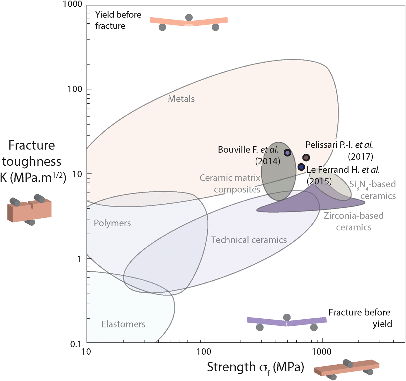
To keep the temperature and corrosion resistance, the hardness and in general the assets of ceramic material intact, the idea emerged to use purely mineral constituents to form a nacre-like aluminas (NLAs) [Reference Bouville, Maire, Meille, Van de Moortèle, Stevenson and Deville46]. The structure, fabricated by ice-templating and field assisted sintering technique (FAST) sintering first, used micron-sized Al2O3 platelets as bricks and an amorphous SiO2 + CaO glass as mortar, with Al2O3 nanoparticles as nano-asperities and bridges. NLAs have been later fabricated through magnetically assisted slip casting (MASC) [Reference Le Ferrand, Bouville, Niebel and Studart52] and hot pressing [Reference Evers, Falco, Grobert and Todd61]. With MASC, the NLAs have been first produced with a SiO2 + CaO glass secondary phase [Reference Le Ferrand, Bouville, Niebel and Studart52] and more recently using a transient liquid phase (TLP) sintering resulting in an aluminium borate [Reference Pelissari, Bouville, Pandolfelli, Carnelli, Giuliani, Luz, Saiz and Studart62] secondary phase. With the right composition, these NLAs presented strength and toughness better than the best technical alumina, but additionally present stable crack propagation. The combination of these properties put them in a region of strength and toughness that traditional tough ceramics could not achieve (Fig. 2). Because only minerals were used, NLAs could additionally be used at temperature up to 1200 °C [Reference Bouville, Maire, Meille, Van de Moortèle, Stevenson and Deville46, Reference Pelissari, Bouville, Pandolfelli, Carnelli, Giuliani, Luz, Saiz and Studart62].
Ashby map of material strength versus toughness. The maximum toughness after crack propagation of NLAs is represented in colored circles. CMC data from Ref. Reference Hillig9, Zirconia-based ceramics from Ref. Reference Hanninck, Kelly and Muddle18, Si3N4 from Refs. Reference Becher6 and Reference Becher, Sun, Plucknett, Alexander, Hsueh, Lin, Waters and Westmoreland11.
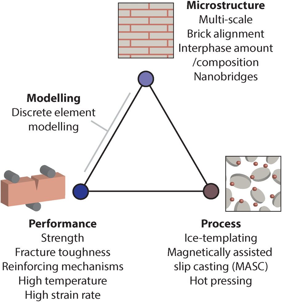
The goal of this review is to summarise all the achievements of these recently developed nacre-inspired ceramics, but also to use the different results obtained so far to draw for the first-time structure/properties/performance relationships (Fig. 3).
Goal of the review: establish the relationship between process/microstructure/performance for NLA.

The first part of the review is dedicated to the processing strategy used to mimic the natural model structure from the millimetre to the nanometre scale, then we will move to describe the link between process and microstructure by comparing the resulting microstructure obtained from three different processes, ice templating, MASC, and hot pressing. Then we will move to the structure/performance relationship by looking at the influence of the different microstructures on the mechanical properties of these ceramic composites, going from quasi-static strength and toughness at room and high temperature to finish with high strain rate and impact properties. We will go through the development of more and more refined discrete element models and show how they are opening the way of a more systematic and complete understanding of the role of the different constituents on the mechanical properties. Finally, this review will provide a picture of the recent development in brick and mortar ceramics and composites in terms of process and achievable strength and toughness to see where NLA fits in this broader context.
We will conclude this review by summarising where we are now and what are the next steps to make these bioinspired structures better yet again, in the hope to finally reach the elusive collective movement of platelets observed in the natural nacre.
Natural nacre performances and how to get a fully mineral composite from the seashell hierarchical blueprint
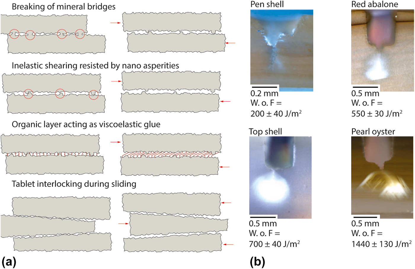
Natural nacre is 40 times tougher than its main constituents, aragonite [Reference Rabiei, Bekah and Barthelat63]. This toughness amplification originates from multiple reinforcing mechanisms programmed into the microstructure. The brick and mortar structure of natural nacre appears deceptively simple but only before looking at the interface between the bricks [Fig. 4(a)]. Mineral asperities are present at the interface and a fraction are connected between two bricks, forming nanobridges of around 30–50 nm diameters [Reference Song, Soh and Bai26]. At the beginning of the fracture, the bridges have first to be broken while the asperities provide friction during the sliding of the bricks. The sliding is further delayed by the protein acting as a viscoelastic glue [Reference Barthelat, Tang, Zavattieri, Li and Espinosa27]. Finally, the bricks present thickness variation, giving a fraction of them a dovetail shape. This feature creates in situ compressive stresses during sliding, promoting damage delocalisation [Reference Barthelat, Tang, Zavattieri, Li and Espinosa27]. These different microstructural features provide in turn multiple reinforcing mechanism during a crack initiation and propagation. Crack deflection at the scale of a few bricks can be observed in most species, providing multiple occurrence of bridging and pull-out mechanisms [see Fig. 4(b)]. Extended microcracking can be observed in some case, with a plastic zone as large as 0.5 mm forming around of the crack tip for some species. Finally, the toughest nacre reported [Pearl Oyster, Fig. 4(b)] presents a combination of extended microcracking and large-scale deflection, with crack propagating at an angle of around 70° from the crack tip and branching and microcracking after this first deflection.
(a) Toughening mechanisms present in natural nacre. (b) Fracture behaviors and associated toughness for different species of nacre. (b) Adapted from Ref. Reference Rabiei, Bekah and Barthelat63.
NLA follow the blueprint of natural nacre from the millimetre to the nanometre scale while replacing the organic mortar present naturally with a mineral.
From the macroscopic point of view, NLA share some optical feature with natural nacre, with visible surface texture effect on mirror polished samples (Fig. 5), although not as beautiful as the iridescence observed in natural nacre. Going from the sample scale to the millimetre scale and below, natural nacre is constituted of almost perfectly aligned bricks of aragonite [Reference Espinosa, Rim, Barthelat and Buehler22], whereas NLA is made of high aspect ratio Al2O3 monocrystal grown by molten salt synthesis [Reference Li-hui and Qing-wei64]. The long-range alignment of the NLA platelets is controlled by the process used. At the tens of micron scale, nacre shows perfectly fitted tablets of aragonite with various degrees of overlap. Some of the tablets present a varying thickness that in some cases forms dovetail shapes [Reference Barthelat, Tang, Zavattieri, Li and Espinosa27]. In NLA, the local alignment of platelets is not only influenced by the process but also by the local packing. The polydispersity of the synthetic platelets used here prevents a perfect packing [Reference Chang, Wu, Zhang, Kupp and Messing65]. At the nanometre scale, natural nacre presents an organic layer and nanoasperities that when connected form nanobridges [Reference Meyers, Lin, Chen and Muyco25, Reference Song, Soh and Bai26]. For the NLA, the organic layer is replaced by a mineral secondary phase that can wet the surface of the Al2O3 and the asperities and nanobridges by nanoparticle of the same material as the platelets. The first secondary phase used was a glass made of SiO2 and CaO, a composition known to facilitate the sintering of alumina [Reference Pavlacka and Messing66], but later an aluminium borate phase has been used to increase the temperature resistance of the whole ceramics [Reference Pelissari, Bouville, Pandolfelli, Carnelli, Giuliani, Luz, Saiz and Studart62].
Strategy used to copy the hierarchical structure of nacre from the centimetre to the nanometre scale. Picture of Nacre: Chris 73 license CC-BY 3.0. SEM of nacre: Dr. Tobias P. Niebel.

We can see that NLA follows the hierarchical structure of nacre from the centimetre to the nanometre, with a strategy that allows for a simple incorporation and control of the secondary phase composition and amount. Starting from the same strategy, the different processes used to fabricate NLA will influence the structure at all these length scales and eventually the final performances.
Process/structure relationship in NLAs
Over the last 6 years, a few different processes have been used to make NLA, from the first use of ice crystal growth to the use of MASC or hot pressing (see Fig. 6).
Overview of the three processes used to make NLAs. (a) Ice-templating, adapted from Ref. Reference Bouville, Maire, Meille, Van de Moortèle, Stevenson and Deville46. (b) MASC, adapted from Ref. Reference Le Ferrand, Bouville, Niebel and Studart52. (c) Hot pressing.
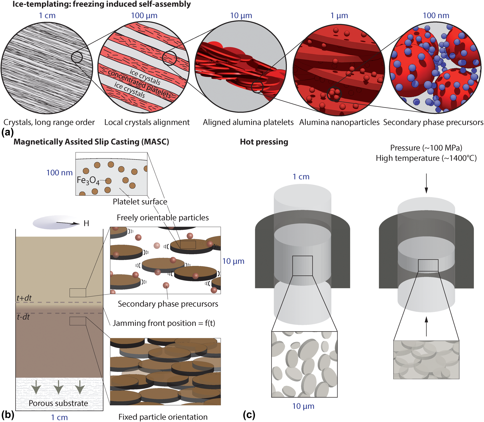
Ice templating uses the directional growth of ice crystals to create controlled porosity in a sample but also to guide self-assembly at the micron scale [Reference Deville67, Reference Deville68]. In this case, the process has to be modified to allow for a complete alignment of the ice crystal and ceramic wall along a plane over centimetre size sample. We use freezing under flow here, that introduce a second gradient by letting the suspension flow on the cooling plate [Reference Bouville, Portuguez, Chang, Messing, Stevenson, Maire, Courtois and Deville69], but more recent and simple techniques could be used for a similar effect [Reference Bai, Chen, Delattre, Tomsia and Ritchie70]. The interphase precursors and nanoparticles can be added at this stage and will be found in the final sample in identical quantity as ice rejects most solid and solute during freezing. After freeze-drying, the sample is cut and pressed along the direction normal to the wall to remove the macroporosity. While pressure is kept, heat is applied to form the secondary phase and allow for grain rearrangement to densify the sample.
MASC is a recently developed process based on the combination of two techniques: the ultra-high magnetic response of micron-sized anisotropic particles [Reference Erb, Libanori, Rothfuchs and Studart71] and slip casting [Reference Lewis72, Reference Adcock and Mcdowall73]. Micron-sized anisotropic particles can respond to low-intensity magnetic fields if super paramagnetic iron oxide nanoparticles are adsorbed on their surface. This phenomenon has been dubbed ultra-high magnetic response as only a field of a few milliteslas can be used to control the orientation and position of micron size objects independently of the base material magnetic susceptibility. Slip casting is one of the oldest ceramic processing techniques in which a suspension, called a slip, is cast on a gypsum mold of any 3D shape. The pores present in the gypsum will suck the solvent out of the slip due to capillary pressure and the particle concentration will increase to form a solid. This solid layer, or cake layer, will grow inside the suspension with defined kinetics based on the diffusion of water in the cake layer and inside the gypsum [Reference Adcock and Mcdowall73, Reference Tiller and Tsai74]. Once either all the suspension is consolidated or the excess slip is removed, the sample can be left to dry. Combining this control of particle orientation in dilute suspension with slip casting, we manage to obtain a process that can simply and rapidly consolidate centimetre-sized sample while controlling perfectly the orientation of the particle inside [Reference Le Ferrand, Bouville and Studart75]. This process can be used to control arbitrarily the orientation of the particles in layer of material, in an additive manufacturing fashion, with a great simplicity and freedom of shape. We recently showed the extent of the design space available and that dense ceramic with controlled texture can even be obtained [Reference Le Ferrand and Bouville76]. This process can be used to produced NLA as well, using a magnet rotating within a horizontal plane. The dried sample is then, as with ice templating, loaded in a dye and hot-pressed to get the final densification.
Finally, hot pressing of anisotropic powder can lead to a simple fabrication of NLA by loading the powder directly into the dye and pressing [Reference Evers, Falco, Grobert and Todd61]. Hot pressing or field assisted sintering technique (FAST, also called Spark Plasma Sintering) have been used and both lead to the same material properties, despite a shorter processing time obtained with FAST. The pressure, along with the heat, will allow the particle rearrangement and better packing, with the particles aligned perpendicular to the pressure direction in the final sample.
These processes play a key role at providing us with new degree of freedom in controlling the key aspect of the microstructure, such as long range alignment of the platelets or interphase composition, but also more practical aspects such as the samples' size and production time.
The process used will determine the degree of control available on the final sample, with the colloid-based processing allowing a better control of the alignment and interphase amount and composition, whereas dry pressing is a simpler and faster route to obtain NLC without any interphase (see Table I).
Comparison of processes on the fabrication of NLA. Platelets misalignment distribution were estimated by image analysis of the microstructure when not explicitly available.

The long-range alignment of the platelets is controlled by the colloidal processing step, with MASC sample presenting a Full Width at Half Maximum (Δω) of the platelet orientation distribution measured by image analysis almost two times lower than the one obtained by ice templating. The FWHM of the simply hot-pressed sample is 30% higher to the one obtained by MASC, with a value of 13° compared to 10° respectively. The misalignment degree Δω obtained with MASC and hot pressing is similar to the one obtained with layer-by-layer process [Reference Bonderer, Studart and Gauckler41], 30% higher than with tape-casting [Reference Pavlacka and Messing66], and similar to the one obtained with natural nacre [Reference Le Ferrand, Bouville and Studart75].
The secondary phase amount and composition as well as the amount of nanoparticles is crucial to control the mechanical properties, and both values are deeply rooted in the colloidal processing step. Ice templating allows to carefully control these parameters as everything that is present in the suspension will be rejected by the growing ice and thus will be found in the final freeze-dried sample. This is also true to a certain extend with MASC as the colloidal dispersion can be controlled before the slip casting, but some of the precursors might end up getting lost by the liquid removal. Only additives adsorbed on the platelets surface can be controlled directly, as attested by the presence in the final sample of the iron oxide nanoparticles, or the SiO2 particles used as nanobridges [Reference Niebel, Bouville, Kokkinis and Studart50]. The direct hot-pressing strategy cannot allow the addition of a secondary phase without an additional colloidal processing step, such as drying, spray-drying or freeze-drying.
There are two main factors influencing the final sample size: the limitation of the process used to align the particles and the limitation of the hot-pressing step necessary to obtain full densification. There is for ice-templating an intrinsic limit to the sample size as there is a limit to a sample height that can be frozen based on minimum temperature of the freezing substrate. This limit can be around 30–40 mm depending on the thermal conductivity of the sample and the cooling medium used. This limit could be broken by using freeze dried powder but probably at the cost of platelets long-range alignment. For MASC, due to the low intensity magnetic field necessary to align the particles, samples up to 150 mm can be produced with Neodymium magnets and larger samples could be achieved using several magnets. In practice, sample of up to 75 mm diameter has been cast [Reference Grossman, Bouville, Erni, Masania, Libanori and Studart59]. At that point, the maximum sample size is dictated by the hot-pressing step. Unlike most spherical alumina powders that can be densified by pressureless sintering, uniaxial pressure of 60–80 MPa is needed [Reference Bouville, Maire, Meille, Van de Moortèle, Stevenson and Deville46, Reference Le Ferrand, Bouville, Niebel and Studart52] to fully densify these alumina platelets samples. With most hot press it translates into a maximum achievable diameter of 50 mm.
Regarding the time necessary to produce a sample, the longest process is the ice templating route, 3 and 10 times longer than MASC and direct hot-pressing respectively, due to the necessary freeze-drying step. Finally, while the direct hot-pressing step is the simplest and fastest processing route, it doesn't allow the addition of secondary phase precursors without a colloidal processing step and thus cannot produce the samples with the highest mechanical properties.
The process chosen to fabricate NLR changes both the degree of control available on the structure at multiple length scales but also introduces some practical constrains on the sample. However, the sintering step will influence the microstructure and the secondary phase composition and crystallinity.
The pressure assisted sintering stage allows the complete densification of the samples but also influences the microstructure by driving grain growth and compositional change at the interface.
The sintering temperature is influenced by the presence of secondary phase and the presence of nanoparticles, almost all the densification occurs within the 1200–1500 °C window [Fig. 7(a)]. During this temperature increase, the grain size will change, driven by a reduction of the surface energy [Reference German77]. The anisotropic grain evolution has been measured for a NLA sample without any interphase [Reference Evers, Falco, Grobert and Todd61]. The values are reported in Fig. 7(b) as l 10, l 50, l 90, and w 10, w 50, w 90 to represent the size obtain at 10, 50, and 90% of the cumulative distribution of the grains apparent diameter l and the thickness w. Both apparent median diameter and thickness increase in size, by 2.6 times and 6.3 times for the diameter and thickness respectively, when temperature increases from 1200 to 1400 °C. This different growth kinetics drives the median aspect ratio  ${s_{50}} = {{{l_{50}}} \over {{w_{50}}}}$ to go from almost 8 down to 3. Since the aspect ratio of the starting material is 30 [Reference Le Ferrand, Bouville and Studart75], these results suggest that the material is going toward its thermodynamic equilibrium structure of equiaxed grains to minimize the grain surface energy. In order to keep the anisotropic structure and obtain the highest mechanical properties, the sintering temperature and time must thus be kept to a minimum while achieving the highest density possible. The use of pressure-assisted sintering allows to have rapid sintering cycles, while the applied pressure and the presence of a secondary phase helps the densification and the sample relative density obtained ranged from 98 to 99% [Fig. 7(c)].
Effect of the process and pressure assisted sintering on the microstructure of NLA. (a) Effect of the secondary phase composition on the sintering temperature, adapted from Ref. Reference Bouville, Maire, Meille, Van de Moortèle, Stevenson and Deville46. (with permission from Elsevier) (b) Evolution of grain size as a function of temperature during hot pressing at 70 MPa, with l 10, l 50, and l 90 the size of the grain long axis and w 10, w 50, and w 90 the size of the grain short axis at 10%, 50%, and 90% of their respective cumulative distribution. Data extracted from Ref. Reference Evers, Falco, Grobert and Todd61. (c) Relative density as a function of the composition of the secondary phase. Data from Refs. Reference Le Ferrand, Bouville, Niebel and Studart52 and Reference Pelissari, Bouville, Pandolfelli, Carnelli, Giuliani, Luz, Saiz and Studart62. (d) X-ray diffractogram of NLA made by TLP (MASC—TLP) sintering with an aluminium borate or without (MASC), adapted from Ref. Reference Pelissari, Bouville, Pandolfelli, Carnelli, Giuliani, Luz, Saiz and Studart62. (e) EBSD map of MASC—TLP. Adapted from Ref. Reference Pelissari, Bouville, Pandolfelli, Carnelli, Giuliani, Luz, Saiz and Studart62 (with permission from Elsevier) (f) Strain calculated from lattice parameters shift measured with Rietveld refinement for both MASC and MASC—TLP, adapted from Ref. Reference Pelissari, Pandolfelli, Carnelli and Bouville80.

Despite the low amount of secondary phase in the final samples, this component has a major influence on both the structure and the mechanical properties. However, the low amount of secondary phase, around 0.5 vol%, makes it also challenging to characterize. The crystallinity and composition could not yet be assessed for the amorphous SiO2 based NLA. The most recent NLA uses a process called TLP sintering, in which the secondary phase is added as an amorphous precursor, here boric acid, that will upon heat treatment in oxygen form an amorphous B2O3 phase. During the pressure-assisted sintering, the liquid B2O3 will help the densification by increasing diffusion and lubricating the contact and finally crystallize at high temperature to form an aluminium borate phase of composition 9Al2O3·2B2O3. Because this phase is crystalline, it was possible to assess its presence both using XRD [Fig. 7(d)] and indirectly using nanoindentations [Reference Pelissari, Bouville, Pandolfelli, Carnelli, Giuliani, Luz, Saiz and Studart62]. EBSD maps on NLA-TLP revealed both the collective crystallographic alignment of the grains and the presence of metallic iron in the structure [Fig. 7(e)], coming from the iron oxide nanoparticles that have sintered and reduced during the pressure-assisted sintering step. Finally, the aluminium borate at the grain boundary present a coefficient of thermal expansion (CTE) 2 times lower than the alumina grains, with a CTE of 4.2 × 10⁻⁶ K−1 for the aluminium borate phase [Reference Ray78] compared to 8 × 10⁻⁶ K−1 for alumina [Reference Munro79]. This difference in CTE introduces anisotropic residual stresses in both phases and, based on Rietveld refinement, lattice strains increases from −4 × 10⁻⁴ up to 8⋅× 10−4 along the crystallographic c-axis of the alumina structure with the addition of the aluminium borate phase [Fig. 7(f)].
The choice of processing techniques and composition of the NLA have drastic impact on the sample's microstructure at multiple length scales, from the long-range alignment of the grains down to the crystallographic lattice strain. All these changes will in turn have an impact on the mechanical properties of these bioinspired composites and especially on their resistance to fracture.
Structure/performance relationship in NLAs
Using the panel of techniques and secondary phase compositions available to produce NLA, it is possible to change the microstructure from the millimetre scale to the nanometre scale. This part of the review will present how these microstructural differences improve the composite's fracture properties in static and dynamic loading.
As nacre-like ceramics bridges several research fields, from bioinspired materials to ceramics and CMC, this part will introduce some of the key notation and parameters that will be used in the rest of the review to describe the fracture properties of NLA.
Fracture processes can present multiple stages [Reference Lawn81]: the first one is the crack initiation from a critical size defect, and K IC is the material properties associated with this phenomenon. For a brittle material this is the only value needed as the crack will become instable after the initiation and can be calculated in crack opening mode (mode I) as  ${K_{{\rm{IC}}}} = {\sigma _{\rm{c}}}Y\sqrt a$, with σc the tensile stress on the sample at crack initiation, Y a geometric factor taking into account the stress concentration at the crack tip and a the defect size. On the load–displacement curve, it corresponds to the first non-linearity [Fig. 8(a)]. If reinforcement mechanisms are present, the crack growth can become stable. From there the load can keep increasing until a maximum load that can be used to calculate another toughness value K Ipb, the apparent toughness, as defined by the ASTM standard [82]. This value is an approximation as the crack size is taken equal to the initial value even if the material is already damaged. During a stable crack propagation, a reinforcement curve (R-curve) can be calculated as the increase in toughness as the crack grows. The crack length increase can be optically measured but if there are multiple cracks, or if the cracks deflect away or have a path too complicated to measure, then the crack length can be estimated from the change in compliance of the sample ΔC [Fig. 8(a)], with the compliance calculated as $C = {u \over f}$. This virtual crack length value can be seen as an estimation of the damaged area in the sample. From these different crack extensions, one can then calculate K, based on the same linear elastic mechanics formula with updated stresses and crack sizes. This is the approach used in most of the ceramic literature [Reference Becher6, Reference Munz83]. For bioinspired materials, the usual approach is to use calculation based on the J-integral model [Reference Rice84], to take into account any plastic mechanisms that could occur and obtain J value at each crack size [82]. The values obtained have the unit of an energy release rate (J/m2) but can then be converted into fracture toughness using $K = \sqrt {JE}$, with E being the material Young's modulus. K J is either taken as the value at which the R-curve saturates or the validity limit of the ASTM standard, whichever comes first. Depending on the article, each of these three values K IC, K Ipb, or K J can be calculated and it is up to the reader to find which one is given as they cannot be directly compared.
Measurement of NLA fracture toughness values. (a) Typical load–displacement curves obtain for Single Edge Notched Beam sample. (b) Value obtain from a typical NLA R-curve. (c) Description of the different reinforcement mechanisms delaying the crack propagation in Nacre like Alumina.

The fracture of NLA occurs with multiple cracks propagating at a deflection angle θ between 70° and 80°. These reinforcements allow for a stable crack propagation and thus both K IC and K Ipb can be calculated from the load–displacement curve. These one or two main cracks grow steadily for several hundreds of microns but eventually another crack will nucleate from an existing one and break the rest of the sample almost instantaneously. Given the reinforcement mechanisms, an equivalent crack length can be calculated from the static compliance variation ΔC, from which an R-curve can be calculated [Reference Ebrahimi, Chevalier, Saadaoui and Fantozzi85, Reference Zehnder86].
The reinforcement mechanisms obtained in the NLA can act at different length scales and on the different toughness values, either during crack initiation, during propagation or both. The presence of compressive residual stresses and a stronger secondary phase will increase both the toughness at crack initiation and during propagation as the crack will need higher stresses to grow, effectively adding a contribution ΔK res and ΔK interface to both K IC and K J. Multiple deflected cracks will also increase the necessary stress to grow the crack by changing the mode of propagation and moving the crack tip away from maximum stress applied, adding a component ΔK deflection to K J [see Fig. 8(c)]. Each of these toughness value will thus be influenced by the microstructural changes resulting from the different processes and secondary phases used.
The mechanical properties at room and high temperature of NLA can be drastically improved by a better control over the microstructure and the addition of tougher and more refractory secondary phase.
Samples made by ice-templating, named Ice T—Glass, and by MASC, named MASC—Glass, share the same composition but present long-range misalignment degree of Δω ∼ 17° and Δω ∼ 10° respectively. The last sample synthesized with the aluminium borate TLP, named MASC—TLP, share the same long-range misalignment degree as the MASC—Glass sample but a different secondary phase composition. The R-curves of the three samples are plotted in Fig. 9(a). The end of the stable crack growth is reached at a crack extension value almost two times lower for both MASC samples compared to the Ice T—Glass sample. The average crack deflection angle θ increases from θ = 70 ± 5° to 82 ± 2° for Ice T—Glass and MASC—Glass samples respectively, as the platelets' orientation distribution sharpens from Δω ∼ 17° to Δω ∼ 10° [Figs. 9(b) and 9(c)]. From these results we can conclude that a smaller spread in platelets orientation drives a larger crack deflection angle θ, which is consistent with an increase in local anisotropy of mechanical properties.
Mechanical properties of NLAs processed by Ice templating or MASC and with different secondary phase compositions: Ice templating and SiO2 + CaO secondary phase (Ice T—Glass), MASC without secondary phase (MASC), with SiO2 + CaO (MASC—Glass), and with a TLP aluminium borate (MASC—TLP). (a) R-curve measurement for Ice T—Glass, MASC—Glass, and MASC—TLP. Data from Refs. Reference Bouville, Maire, Meille, Van de Moortèle, Stevenson and Deville46, Reference Le Ferrand, Bouville, Niebel and Studart52, and Reference Pelissari, Bouville, Pandolfelli, Carnelli, Giuliani, Luz, Saiz and Studart62. Pictures of crack propagation obtained for Ice T—Glass (b) and MASC—Glass (c), with the average deflection angle θ measured on 4 samples or more. (d) Fracture toughness at crack initiation (K IC), apparent fracture toughness (K Ipb), R-curve maximum toughness (K J) for different nacre like alumina along with microstructure misalignment angle Δω. (e) Strength measured in three point bending for different NLAs samples. (f) Apparent fracture toughness K Ipb values for NLA and hot-press alumina, alumina reinforced SiC platelets. Reference value for alumina from Refs. Reference Belmonte, Moya, Miranzo, Nguyen, Dubois and Fantozzi13 and Reference Munro79.

The three toughness values K IC, K Ipb, and K J obtained with no secondary phase, the Glass and the TLP composition as well as the two different processes are summarized in Fig. 9(d), along with typical values obtained for alumina. The K IC values increases with the addition of stronger secondary phases, with an increase of 30% with the addition of the Glass phase, irrespective of the process used, and an increase of 70% with the addition the TLP to reach a K IC value of 7.4 MPa m1/2. The K IC of the MASC—TLP represents a 2-fold increase compared with conventional Al2O3. The platelet misalignment does not seem to influence the K IC as the values obtained for both Ice T—Glass and MASC—Glass are similar. Both K Ipb and K J reached similar values for all MASC samples whereas a factor 2 difference exists between these toughness values in Ice T—Glass. This discrepancy can arise from the calculation method used as the crack length is calculated using a compliance variation method. More advanced models of mix-mode propagation calculation or J-integral calculation based on measured or simulated stresses should eventually be used to push further our understanding of NLA toughness.
The strength of the NLA compositions are reported in Fig. 9(e) along with the strength of conventional and hot-pressed aluminas [Reference Munro79]. The strength of the NLA increases with the addition of stronger secondary phases, with a factor 2 and 2.3 increase between MASC and MASC—Glass and MASC—TLP respectively. This increase brings the value of MASC—Glass and MASC—TLP higher than the strength of conventional hot-pressed alumina, while presenting reinforcing mechanisms absent in the non-bioinspired ceramics. Whereas the general strength evolution follows the increase of K IC, the 30% strength difference between the Ice T—Glass and MASC—Glass sample suggests that the MASC process introduces smaller defects during the fabrication.
In addition to these impressive mechanical properties at room temperature for purely mineral composites, all the NLA composition can be used at high temperature as well. The K Ipb of MASC, MASC—TLP and Ice T—Glass are represented as a function of temperature in Fig. 9(f), from room temperature to 1200 °C, along with hot-pressed alumina [Reference Munro79] and SiC platelets reinforced alumina [Reference Belmonte, Moya, Miranzo, Nguyen, Dubois and Fantozzi13]. The K Ipb of all NLA samples are higher than the two references materials across the whole range of temperature, suggesting that the reinforcing mechanisms are maintained at high temperature.
Besides the comparison between NLA, there are now quite a few nacre-like composites with ceramic content higher than 60 vol% that have been produced using one of the three processes described above and the same alumina platelets but used either a polymer or metallic secondary phase. Additionally, the presence of a polymer or metallic phases implies both multiple additional synthesis steps and a decrease in high temperature or corrosion properties. While the addition of more ductile and compliant phases should in theory increase composites resistance to crack growth, experimental results show the opposite trend (Fig. 10). NLA-TLP have a K IC equal or higher than all other nacre-like composites with both polymer [Reference Niebel, Bouville, Kokkinis and Studart50, Reference Grossman, Bouville, Erni, Masania, Libanori and Studart59] and metallic phases [Reference Huang, Rubink, Lide, Scharf, Banerjee and Minary-Jolandan53, Reference Huang, Daryadel and Minary-Jolandan54, Reference Wat, Ferraro, Deng, Sweet, Tomsia, Saiz and Ritchie56] while presenting strength 2 times higher than all the other nacre-like composites. The K J of MASC—TLP is only bested by two compositions, Ice T-glass and a composite made with a mixture of nickel metal and nickel oxide.
Ashby map of strength versus toughness of nacre-like composite and NLAs based on the same monocrystalline alumina bricks. Both toughness at crack initiation K IC (full dots) and maximum toughness during crack propagation K J (empty dots) are represented for all composites. Nacre-like composite with polymer secondary phase: MASC PUA-PHEMA [Reference Niebel, Bouville, Kokkinis and Studart50], MASC TiO2—epoxy [Reference Grossman, Bouville, Erni, Masania, Libanori and Studart59]. Nacre-like composite with metallic secondary phase: Ice T Ni [Reference Huang, Rubink, Lide, Scharf, Banerjee and Minary-Jolandan53], Ice T copper [Reference Huang, Daryadel and Minary-Jolandan54], MASC copper [Reference Le Ferrand, Bouville, Niebel and Studart52], pressing Ni/NiO [Reference Wat, Ferraro, Deng, Sweet, Tomsia, Saiz and Ritchie56].

Quasi-static thermostructural results obtained so far show that NLA properties can be drastically improved by a careful tuning of the microstructure. However, more work is needed to fully understand and characterize the crack growth and the multiple reinforcing mechanisms that can be further improved. Because the reinforcing mechanisms are based on purely brittle constituents, NLA could provide also higher resistance to high strain rate/impact fracture.
The resistance to high strain rate deformations and impact of NLA is better than monolithic alumina as it presents multiple reinforcing mechanisms that can dissipate the impact energy.
Evers et al. [Reference Evers, Falco, Grobert and Todd61] used both a split Hopkinson bar test and impact testing to probe the response of hot pressed NLA at strain rate of 500 ± 100 s−1 and impact kinetic energies from 1 to 4.5 kJ. The split Hopkinson bar results, shown in Fig. 10(a), demonstrate the drastic change in behavior from monolithic alumina to NLA, with a strain at failure almost 2 times higher for the NLA, along with a yield stress increase of around 60%. The greater resistance to high strain rate stress of NLA compared to monolithic alumina is illustrated further during the impact testing using 3 mm steel projectile impacting the surface at energy from 1 to 4.5 kJ. First of all, all NLA specimens are whole after impact, compared to the monolithic alumina broken in multiple pieces. The observation of NLA samples after impact shows [Figs. 11B] that multiple fractures are present inside the sample from the impact point, all deflecting away from the impact region. The reinforcing mechanisms observed in quasi-static testing seems to be happening as well at high strain rate, but from multiple sources this time as the acoustic wave responsible for the failure can activate multiple defects simultaneously.
High strain rate properties of NLA produced by pressing. (A) Stress–strain curves of NLA compare to conventional alumina in compression obtained at a strain rate of 500 ± 100 s−1 during a split Hopkinson bar test. (B) Pictures of NLA sample front (a) and back (b) after impact testing with steel sphere projectile. Adapted from Ref. Reference Evers, Falco, Grobert and Todd61 (with permission from Elsevier)

The increase in strength and toughness observed at low and high strain rate in NLA finds its root into the way the different brittle components are structured. Being able to model the fracture behavior would shed light on the link between structure and properties and eventually open rational improvement pathways.
Mechanical modelling of nacre-like materials made of perfectly linear elastic constituents
Multiple models based on periodic unit cell have been developed to answer the puzzle that is natural nacre mechanical properties [Reference Sakhavand and Shahsavari87, Reference Barthelat and Mirkhalaf88, Reference Barthelat89, Reference Abid, Mirkhalaf and Barthelat90, Reference Begley, Philips, Compton, Wilbrink, Ritchie and Utz91, Reference Ni, Song, Jiang, Yu and He92].
These models used periodic unit cell and elasto-plastic mortar to explore the effect of characteristic lengths [Reference Ni, Song, Jiang, Yu and He92], bricks overlap [Reference Barthelat89], and failure sequence [Reference Begley, Philips, Compton, Wilbrink, Ritchie and Utz91] on the composites stiffness, strength, and toughness. Several critical conclusions have been drawn by these studies. The first one is that brick and mortar structure is advantageous only for high volume fraction of bricks and with bricks at least five time stronger than the mortar [Reference Barthelat89]. The second one is that under specific combination of elasto-plastic properties and sizes, a brick and mortar structure can become insensitive to brick overlapping distribution [Reference Ni, Song, Jiang, Yu and He92]. Finally, the strength and toughness can be further optimised by designing the properties of both components to fail in a certain order: vertical yielding of the mortar, then horizontal yielding, then fracture of the vertical interface and finally fracture of the horizontal ones [Reference Begley, Philips, Compton, Wilbrink, Ritchie and Utz91]. However, only recent simulations based on discrete element method can get closer to real microstructures by introducing random brick size variation but also explain the results obtained with purely brittle constituents.
Discrete element method allows to perfectly model the behavior of linear elastic brittle materials by tuning the interaction potential parameters existing between separate elements. This technique used in nacre-inspired structure has recently highlighted the detrimental effect of random variation of bricks size on toughness in nacre-inspired materials [Reference Abid, Mirkhalaf and Barthelat90], explaining the discrepancy observed in real microstructure compared to perfect unit cell models. Using DEM method with spring interaction potentials and finite strain allowed Dimas et al. [Reference Dimas and Buehler93] to study the fracture propagation in brick and mortar structure made of two brittle constituents with different stiffnesses but identical modulus of toughness. The modulus of toughness represents the area under the stress strain curve of a material in tension and is thus a quantification of the energy necessary to break a pristine material. The fracture propagates first only in the mortar then in a mix of mortar and bricks failure to finally having a brittle failure as the stiffness ratio increases from 0.02 to 1. The maximum toughness is obtained in this case with a stiffness ratio of 0.5. More recently, Radi et al. [Reference Radi, Jauffrès, Deville and Martin94] uses directly the mechanical properties of Ice T—Glass as starting point for a discrete element model, using in this case a microscopic beam type interaction to link the individual elements together. The trends observed are consistent with the previous models, with first a region in which the failure occurs only in the mortar [region 1 Fig. 12], then in a mix between brick and mortar failure [region 2 Fig. 12], finally with a brittle failure of the bricks first [region 3 Fig. 12] as the strength of the mortar increases from 50 to 4000 MPa, compared to brick strength of 5300 MPa [Reference Feilden, Giovannini, Ni, Ferraro, Saiz, Vandeperre and Giuliani95] in average. Today NLA produced with SiO2 + CaO or aluminium borate secondary phase present a theoretical strength ratio of  ${\Sigma \over {{\Sigma _t}}} = 0.09$ and ${\Sigma \over {{\Sigma _t}}} = 0.13$, thus with still quite a way to go up to the optimum theoretical strength ratio of ${\Sigma \over {{\Sigma _t}}} = 0.4$.
Discrete element models of purely brittle brick and mortar composites. Strength Σ of discrete element model of NLA relative to the brick strength Σt as a function of the strength of the secondary phase Σi. Adapted from Ref. Reference Radi, Jauffrès, Deville and Martin94 (with permission from Elsevier)

The continuous improvement of the models that can be used for NLA will open a more rational design of the material properties. Because the models are based on discrete element method, properties such as polydispersity of the brick and mortar dimensions could be eventually integrated to help us fully understand the fracture behavior of these ceramics.
Position of nacre-like ceramics within the brick-and-mortar composite landscape
Multiple nacre inspired have been produced, from large alumina grains ceramic to fully polymeric structures. This review will focus on bulk bioinspired composites containing more than 50% ceramic content in volume to fit within the same targeted niche of stiff, strong, and tough structural materials as NLA. The first high performance and high ceramic content brick and mortar were developed in 2008 by Munch et al. [Reference Munch, Launey, Alsem, Saiz, Tomsia and Ritchie96], reaching value of toughness up to 30 MPa m1/2 and moderate strengths of around 200 MPa. These structures have been reproduced more recently with either the same components or different mineral/organic phase, reaching toughness values of 7 MPa m1/2 for similar composition of alumina/polymer [Reference Askarinejad and Rahbar51] composites, around 4.5 MPa m1/2 for hydroxyapatite/PMMA [Reference Bai, Walsh, Gludovatz, Delattre, Huang, Chen, Tomsia and Ritchie39] or around 9 MPa m1/2 for zirconia/dental resin [Reference Tan, Zhang, Zheng, Jiao, Liu, Zhang and Ritchie97] composites. Figure 13 provides a picture of the structural performances of nacre-inspired ceramics or composites by comparing both toughness at crack initiation K IC and maximum valid toughness after crack propagation K J as a function of the composite bending strength. When several studies were available, only the one made in the last 10 years are plotted to give an idea of what is achievable with today's processing advances and to preserve the figure clarity. All the data for Fig. 13 along with the references used are available in Table II. There are so far 7 reported processes used to make bulk brick and mortar composites available in the literature, with the accompanying range of control of the microstructure and processing time/limits. Correspondingly, the range of toughness and strength values achievable for brick and mortar structure is broad, with strengths ranging from 20 MPa to 660 MPa, K IC from 1 MPa m1/2 to 7.8 MPa m1/2, and K J from 3 MPa m1/2 to 17 MPa m1/2. The strength increases with decreasing brick size (see Table II), or grain size in the case of ceramic laminates, and follows the increase in toughness at crack initiation. The effect of the secondary phase seems to have the most influence on the strength and toughness values at the exception of a few outliers, with polymer and metal sharing a common property space, and fully ceramic composites allowing for higher strengths and comparable toughness. Both toughness values seem to be relatively independent of the toughness of the secondary phase, with the highest toughness reached for metallic nickel, silica glass, graphite or even zirconium-based metallic glasses, whereas their respective toughness are around 100 MPa m1/2, 0.5 MPa m1/2, 1 MPa m1/2, and 150 MPa m1/2 respectively. The toughness seems to be more dependent on the microstructure and extrinsic reinforcing mechanisms. In most cases, local crack deflection, bridging and pull-out can be observed, with some instance of microcracking in the 50 µm vicinity of the crack [Reference Tan, Zhang, Zheng, Jiao, Liu, Zhang and Ritchie97], whereas large scale deflection observable in laminates and NLAs. Despite all these advances, a plastic zone in front of the crack tip as large as the ones observed in natural nacre has yet to be achieved in bioinspired composites.
Toughness at crack initiation K IC and maximum valid toughness K J as a function of bending strength of bioinspired ceramics and composites made with various processes, mineral phases, and secondary phases. Raw data and references are available in Table II.

Processing and structural properties of brick and mortar materials.

a K J value calculated from the available work of fracture WoF using  $K_{\rm{J}}^{{\rm{WOF}}} = \sqrt {{\rm{WoF}}\;E}$ with E the material measured Young's modulus.
In conclusion, nacre inspired materials come now in multiple processes, compositions, microstructure sizes, and corresponding structural properties. The highest strengths are obtained with a combination of small particle sizes and processes leaving the smallest defect whereas the highest toughness values are obtained for various combination of extrinsic reinforcing mechanisms and/or tough mortars.
Summary and future directions
Nacre like aluminas are strong, tough, and stiff thermo-structural ceramics that have the essential benefit of being processable as conventional monolithic technical ceramics. Consequently, they can be more easily and readily processed than CMCs. Compared to the other gold standards of tough ceramics, zirconia, the reinforcement mechanism developed here are not composition nor temperature dependent and can thus be used for any material in extreme conditions.
In this review, I explored the links between process/structure/properties of NLA that has been discovered in the last 6 years since the first article to in the end compare their properties with the broader nacre inspired composites literature. NLA has been produced so far with ice templating, MASC and hot pressing. Each process influences the structure in terms of platelets alignment and control of the composition of the interface, with MASC providing the best alignment and ice templating a better control of the composition. These processes have been used to produce three main different compositions, one with no secondary material at the interface, one made of an amorphous SiO2 and CaO, one made of on a crystalline aluminium borate of composition 9Al2O3·2B2O3. All of these compositions also contain Al2O3 nanoparticles that can act as both nanoasperities and nanobridges. By comparing all the available data on fracture toughness and strength, we can provide clear link between the structure and properties: the stronger the secondary phase, the higher the toughness at crack initiation, with a 2-fold increase in K IC from no interphase to the 9Al2O3·2B2O3. The main reinforcement mechanism of the NLA is crack deflection, which can be influenced by the quality of the long-range alignment. In brittle materials, strength and toughness are mutually beneficial properties, which is confirmed here as the 2-fold increase in toughness is translated into a 2-fold increase in strength. Because the reinforcement mechanisms are based on brittle constituent, they are present at high temperature but also at high strain rates, imbuing the bioinspired composite with high toughness at temperature up to 1200 °C and high impact resistance compared with monolithic alumina. Within the nacre inspired composites landscape, nacre like aluminas present higher strengths and comparable toughness values compared to the newest composites made with polymeric or metallic secondary phased. The high strength comes from a combination of small brick size and less defects introduced using MASC. NLA high toughness seems to come primarily from large-scale deflection, whereas the other brick and mortar structure presents more local deflection, crack bridging, some microcracking, and pull-out.
From these conclusions, there are several pathways open to push these bioinspired ceramics further. Models already suggest that we can significantly improve the mechanical properties by fine tuning the secondary phase properties. On a more fundamental level, the fracture process is still not clearly understood, with the complex interplay of large-scale deflection and local toughening at the platelet interface level. Finding a way to decouple both effects, either experimentally or with the help of analytical and advanced modelling tools, would help us rationalise the next generation design to reach even higher properties. Regarding high temperature and high strain rate, we have already reached the point where the intrinsic properties of the alumina limits the performance. Because all the principles used here are composition independent, it will soon be time to go beyond alumina and start developing nacre-like ceramics with intrinsically stronger or more temperature resistant compositions.
For brick-and-mortar composites in general, the introduction of stronger material as secondary interface improved the mechanical properties and new processes allow us to translate more and more features from the natural blueprint to our materials. There are two main features that are however still eluding us: the fabrication of composites with monodisperse brick/mortar sizes and brick thickness variations. These two features have been identified as critical during modelling and experimental studies on natural nacre. While it is possible to produce millimetre scale models with these features using additive manufacturing, there are simply no process available yet to do that at the micron/nano scale where we could harness the high strength of the individual brittle elements as well. The toughness of natural nacre is 40 times higher than its main constituents so if we manage to obtain a similar toughness amplification with alumina, we could reach a toughness on par with the toughest metals we can make.
Finally, and probably because of the process limitations discussed above, there is one last reason telling us that we have not reached the full potential of nacre inspired ceramics and composites: natural nacre displays collective movement of bricks that allow certain species to deform plastically up to a few percents, a feat that has yet to be observed in highly mineralized nacre-inspired materials.
Acknowledgments
The author is indebted to Dr. Tobias P. Niebel, who allowed the use of the beautiful pictures of natural nacre he took. The author's thanks also go to Dr. Pedro Ivo Pelissari, Dr. Sylvain Deveille, Prof. André Studart, Prof. Eduardo Saiz, and Dr. Finn Giuliani for the numerous discussions (and the ones yet to come) on the peculiar fracture behavior of the Nacre-like alumina.


 Open access