1 Introduction
The detection of flares from Crab nebula by AGILE and Fermi satellites (Abdo et al. Reference Abdo, Ackermann, Ajello, Allafort, Baldini, Ballet, Barbiellini and Bastieri2011; Tavani et al. Reference Tavani, Bulgarelli, Vittorini, Pellizzoni, Striani, Caraveo, Weisskopf and Tennant2011; Buehler et al. Reference Buehler, Scargle, Blandford, Baldini, Baring, Belfiore, Charles, Chiang, D’Ammando and Dermer2012) is one of the most astounding discoveries in high-energy astrophysics. The unusually short durations, high luminosities and high photon energies of the Crab nebula gamma-ray flares require reconsideration of our basic assumptions about the physical processes responsible for acceleration of the highest-energy emitting particles in the Crab nebula, and, possibly in other high-energy astrophysical sources.
The Crab flares are characterized by an increase of gamma-ray flux above 100 MeV by a factor of few or more on the day time scale. This energy corresponds to the high end of the Crab’s synchrotron spectrum. Most interestingly, in the other energy bands nothing unusual has been observed during the flares so far (Weisskopf et al. Reference Weisskopf, Tennant, Arons, Blandford, Buehler, Caraveo, Cheung, Costa, de Luca and Ferrigno2013). This suggests that the physical processes behind the flares lead to a dramatic increase of the highest-energy population of relativistic electrons in the nebula, whereas lower-energy population remains largely unaffected. The short duration of flares indicate explosive and highly localized events.
Most importantly, the peak of the flare spectrum approaches and even exceeds the maximal rest-frame synchrotron photon energy (de Jager et al.
Reference de Jager, Harding, Michelson, Nel, Nolan, Sreekumar and Thompson1996; Lyutikov Reference Lyutikov2010; Clausen-Brown & Lyutikov Reference Clausen-Brown and Lyutikov2012). Balancing the synchrotron energy losses in the magnetic field
 $B$
against the energy gain via acceleration in the electric field of strength
$B$
against the energy gain via acceleration in the electric field of strength
 $E=\unicode[STIX]{x1D702}B$
leads to the upper limit of the synchrotron photon energy
$E=\unicode[STIX]{x1D702}B$
leads to the upper limit of the synchrotron photon energy
 $$\begin{eqnarray}\unicode[STIX]{x1D716}_{\max }\sim \unicode[STIX]{x1D702}\hbar \frac{mc^{3}}{e^{2}}\approx 100\unicode[STIX]{x1D702}~\text{MeV}.\end{eqnarray}$$
The high conductivity of astrophysical plasma ensures that for typical accelerating electric field
 $\unicode[STIX]{x1D702}<1$
. The fact that the flare spectrum extends beyond this limit pushes
$\unicode[STIX]{x1D702}<1$
. The fact that the flare spectrum extends beyond this limit pushes
 $\unicode[STIX]{x1D702}$
towards unity, which implies energy gain on the scale of the gyration period. This practically excludes stochastic acceleration mechanisms in general and the shock acceleration in particular. In principle, strong Doppler boosting could somewhat reduce this constraint (Bednarek & Idec Reference Bednarek and Idec2011; Clausen-Brown & Lyutikov Reference Clausen-Brown and Lyutikov2012) but the lack of observational evidence for ultra-relativistic macroscopic motion inside the nebula makes this unlikely.
$\unicode[STIX]{x1D702}$
towards unity, which implies energy gain on the scale of the gyration period. This practically excludes stochastic acceleration mechanisms in general and the shock acceleration in particular. In principle, strong Doppler boosting could somewhat reduce this constraint (Bednarek & Idec Reference Bednarek and Idec2011; Clausen-Brown & Lyutikov Reference Clausen-Brown and Lyutikov2012) but the lack of observational evidence for ultra-relativistic macroscopic motion inside the nebula makes this unlikely.
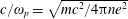
A widely discussed alternative to the shock acceleration mechanism is the particle acceleration accompanying magnetic reconnection. It is well known that magnetic reconnection can lead to explosive release of magnetic energy, e.g. in solar flares. However, properties of plasma in the Crab nebula, as well as magnetospheres of pulsars and magnetars, pulsar winds, active galactic nuclei (AGN) and gamma ray bursts (GRB) jets and other targets of relativistic astrophysics, are very different from those of more conventional solar and laboratory plasmas (Lyutikov & Lazarian Reference Lyutikov and Lazarian2013). In particular, the energy density of magnetic field can exceed not only the thermal energy density but also the rest mass energy density of plasma particles. In order to quantify such a strong magnetization, it is convenient to use the relativistic magnetization parameter
 $$\begin{eqnarray}\unicode[STIX]{x1D70E}=\frac{B^{2}}{4\unicode[STIX]{x03C0}w},\end{eqnarray}$$
where
 $w=\unicode[STIX]{x1D70C}c^{2}+(\hat{\unicode[STIX]{x1D6FE}}p/\hat{\unicode[STIX]{x1D6FE}}-1)$
is the relativistic enthalpy, which includes the rest mass energy density of plasma. In traditional plasmas this parameter is very small but in relativistic astrophysics
$w=\unicode[STIX]{x1D70C}c^{2}+(\hat{\unicode[STIX]{x1D6FE}}p/\hat{\unicode[STIX]{x1D6FE}}-1)$
is the relativistic enthalpy, which includes the rest mass energy density of plasma. In traditional plasmas this parameter is very small but in relativistic astrophysics
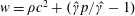
 $\unicode[STIX]{x1D70E}\gg 1$
is quite common. This parameter is uniquely related to the Alfvén speed
$\unicode[STIX]{x1D70E}\gg 1$
is quite common. This parameter is uniquely related to the Alfvén speed
 $v_{A}$
via
$v_{A}$
via
 $$\begin{eqnarray}(v_{A}/c)^{2}=\unicode[STIX]{x1D70E}/(1+\unicode[STIX]{x1D70E}).\end{eqnarray}$$
The physics of particle acceleration in relativistic current sheets has been addressed in a number of recent studies (e.g. Bessho & Bhattacharjee Reference Bessho and Bhattacharjee2012; Deng et al. Reference Deng, Li, Zhang and Li2015; Guo et al. Reference Guo, Liu, Daughton and Li2015; Nalewajko et al. Reference Nalewajko, Uzdensky, Cerutti, Werner and Begelman2015, and others). In particular, the Colorado group (Uzdensky, Cerutti & Begelman Reference Uzdensky, Cerutti and Begelman2011; Cerutti, Uzdensky & Begelman Reference Cerutti, Uzdensky and Begelman2012a ; Cerutti et al. Reference Cerutti, Werner, Uzdensky and Begelman2012b , Reference Cerutti, Werner, Uzdensky and Begelman2013) explored the possibility of explaining the Crab flares. Their two-dimensional (2-D) particle-in-cell (PIC) simulations demonstrated the development of the relativistic tearing instability (see also Lyutikov Reference Lyutikov2003; Komissarov, Barkov & Lyutikov Reference Komissarov, Barkov and Lyutikov2007), followed by a transition to the plasmoid-dominated regime. In addition to a number of useful properties, the current sheet reconnection has some generic features which seem to be in conflict with the observations of the Crab flares.
First, in the collisionless plasma the key length scales of reconnection current sheet are microscopic and determined by to the plasma skin depth. This applies to the thickness of the current sheet, the distance between plasmoids (magnetic ropes) and the correlation scale of the accelerating electric field. As a result the typical potential available for linear acceleration is limited to that over microscopic scales (few skin depths), which is too small to explain the flares spectrum. The correlation scale can be increased with introduction of strong guide field but this leads to a significant reduction of the reconnection rate (Zenitani & Hoshino Reference Zenitani and Hoshino2008).
Second, the recent PIC studies of relativistic reconnection have demonstrated that even in the absence of the guide field the reconnection rate (inflow velocity) in 3-D simulations is significantly lower than in two dimensions (Sironi & Spitkovsky Reference Sironi and Spitkovsky2014). Thus, for a reference magnetization
 $\unicode[STIX]{x1D70E}=10$
the reconnection rate in two dimensions is
$\unicode[STIX]{x1D70E}=10$
the reconnection rate in two dimensions is
 $r_{\text{rec}}\sim 0.1$
whereas in three dimensions it is only
$r_{\text{rec}}\sim 0.1$
whereas in three dimensions it is only
 $r_{\text{rec}}\sim 0.02$
(Sironi & Spitkovsky Reference Sironi and Spitkovsky2014). The slower reconnection rate leads to a weaker accelerating electric field. Moreover, for a given flare duration it translates into a smaller utilized magnetic energy.
$r_{\text{rec}}\sim 0.02$
(Sironi & Spitkovsky Reference Sironi and Spitkovsky2014). The slower reconnection rate leads to a weaker accelerating electric field. Moreover, for a given flare duration it translates into a smaller utilized magnetic energy.
Finally, and most importantly, Crab flares require acceleration to Lorentz factors
 $\unicode[STIX]{x1D6FE}\sim 10^{9}$
. In the simulations of Uzdensky et al. (Reference Uzdensky, Cerutti and Begelman2011) and Cerutti et al. (Reference Cerutti, Uzdensky and Begelman2012a
,Reference Cerutti, Werner, Uzdensky and Begelman
b
, Reference Cerutti, Werner, Uzdensky and Begelman2013) all the particles present within the acceleration region get accelerated to similar energies. In such a case, the terminal Lorentz factor is limited by
$\unicode[STIX]{x1D6FE}\sim 10^{9}$
. In the simulations of Uzdensky et al. (Reference Uzdensky, Cerutti and Begelman2011) and Cerutti et al. (Reference Cerutti, Uzdensky and Begelman2012a
,Reference Cerutti, Werner, Uzdensky and Begelman
b
, Reference Cerutti, Werner, Uzdensky and Begelman2013) all the particles present within the acceleration region get accelerated to similar energies. In such a case, the terminal Lorentz factor is limited by
 $\unicode[STIX]{x1D6FE}_{\max }\sim \unicode[STIX]{x1D70E}$
, which requires unreasonably highly magnetized regions to exist inside the Crab nebula.
$\unicode[STIX]{x1D6FE}_{\max }\sim \unicode[STIX]{x1D70E}$
, which requires unreasonably highly magnetized regions to exist inside the Crab nebula.
These problems may stem from the simplified slab (or, plane-parallel) geometry of the initial configuration, enforced by the periodic boundary conditions, which was considered in the above studies. Indeed, this excludes the large-scale magnetic stresses which in highly magnetized plasma may lead to explosive high-speed dynamics on macroscopic length scales. In this series of papers, we explore the role of the macroscopic factor by considering various initial configurations and studying their macroscopic evolution using fluid-type models of magnetized relativistic plasma. Each such study is accompanied by PIC simulations, which allows us to study the specifics of particle acceleration resulted from the involved magnetic reconnection. We start by considering the classical problem of the X-point collapse.
The theoretical studies of the X-point collapse trace back to the work by Dungey (Reference Dungey1953), who argued that a neutral X-point is unstable and that particles can be accelerated during its collapse. The ideas of Dungey were put on a firm basis by Imshennik & Syrovatskiǐ (Reference Imshennik and Syrovatskiǐ1967), who found corresponding nonlinear MHD solutions (see also Priest & Forbes Reference Priest and Forbes2000). The solutions of Imshennik & Syrovatskiǐ (Reference Imshennik and Syrovatskiǐ1967), Sweet (Reference Sweet1969) and Syrovatskii (Reference Syrovatskii1981) were obtained in what we can nowadays call a quasi-static force-free approximation: neglecting the pressure effects (hence force free), but also neglecting the dynamic effects of the electric field (hence the name quasi-static). In this paper we extend these studies by considering the case of highly magnetized plasma (
 $\unicode[STIX]{x1D70E}\gg 1$
).
$\unicode[STIX]{x1D70E}\gg 1$
).
We start by describing an approximate analytical solution found in the framework of force-free electrodynamics (§ 2). The solution shows that in highly magnetized plasma X-points remain unstable to collapse. This result is verified by our numerical simulations, which also allow a more comprehensive study the dynamics of X-point collapse (§§ 3 and 4). Using 2-D particle-in-cell simulations, we studied the process of non-thermal particle acceleration accompanying the collapse (§ 4). The results show a number features, which have not been seen in previous studies, focused on relativistic reconnection in plane current sheet, and which may have important implications in the theory of Crab flares. In § 5 we summarize our main results and discuss their implications.
2 Asymptotic model of X-point collapse in force-free plasma
2.1 Dynamic force-free plasma
Explosive release of magnetic energy is a common phenomenon in laboratory and space plasmas (e.g. Priest & Forbes Reference Priest and Forbes2000). Syrovatskiǐ (Imshennik & Syrovatskiǐ Reference Imshennik and Syrovatskiǐ1967; Syrovatskii Reference Syrovatskii1975, Reference Syrovatskii1981) argued that it could be related to the macroscopic instability of magnetic X-point configuration and studied it in the framework of non-relativistic MHD (see also Cowley & Artun Reference Cowley and Artun1997). In this section, we develop this theory farther by considering the case of highly magnetized relativistic plasma with
 $\unicode[STIX]{x1D70E}\gg 1$
. In this regime, (i) the mass density of plasma is dominated by the magnetic field, (ii) the Alfvén speed approaches the speed of light, (iii) the conduction current flows mostly along the magnetic fieldlines, (iv) the displacement current
$\unicode[STIX]{x1D70E}\gg 1$
. In this regime, (i) the mass density of plasma is dominated by the magnetic field, (ii) the Alfvén speed approaches the speed of light, (iii) the conduction current flows mostly along the magnetic fieldlines, (iv) the displacement current
 $(c/4\unicode[STIX]{x03C0})\unicode[STIX]{x2202}_{t}\boldsymbol{E}$
may be comparable to the conduction current,
$(c/4\unicode[STIX]{x03C0})\unicode[STIX]{x2202}_{t}\boldsymbol{E}$
may be comparable to the conduction current,
 $\boldsymbol{j}$
, (v) the electric charge density,
$\boldsymbol{j}$
, (v) the electric charge density,
 $\unicode[STIX]{x1D70C}_{e}$
, may be of the order of
$\unicode[STIX]{x1D70C}_{e}$
, may be of the order of
 $j/c$
.
$j/c$
.
The large value of
 $\unicode[STIX]{x1D70E}$
(or small
$\unicode[STIX]{x1D70E}$
(or small
 $1/\unicode[STIX]{x1D70E}$
) can be used as an expansion parameter in the equations of relativistic magnetohydrodynamics. The zero-order equations describe the so-called force-free electrodynamics or magnetodynamics (Komissarov Reference Komissarov2002). In this approximation, the inertia of plasma particle is ignored and hence the macroscopic Lorentz force completely vanishes. Hence the energy and momentum of the electromagnetic fields are conserved. The perfect conductivity condition reduces to
$1/\unicode[STIX]{x1D70E}$
) can be used as an expansion parameter in the equations of relativistic magnetohydrodynamics. The zero-order equations describe the so-called force-free electrodynamics or magnetodynamics (Komissarov Reference Komissarov2002). In this approximation, the inertia of plasma particle is ignored and hence the macroscopic Lorentz force completely vanishes. Hence the energy and momentum of the electromagnetic fields are conserved. The perfect conductivity condition reduces to
 $\boldsymbol{E}\boldsymbol{\cdot }\boldsymbol{B}=0$
and
$\boldsymbol{E}\boldsymbol{\cdot }\boldsymbol{B}=0$
and
 $E^{2}<B^{2}$
, which ensure existence of inertial frames where
$E^{2}<B^{2}$
, which ensure existence of inertial frames where
 $\boldsymbol{E}=0$
.
$\boldsymbol{E}=0$
.
The electric current of ideal force-free electrodynamics can be written entirely in terms of the electromagnetic field and its spatial derivatives
 $$\begin{eqnarray}\boldsymbol{J}=\frac{c}{4\unicode[STIX]{x03C0}}\frac{(\boldsymbol{E}\times \boldsymbol{B})\unicode[STIX]{x1D735}\boldsymbol{\cdot }\boldsymbol{E}+(\boldsymbol{B}\boldsymbol{\cdot }\unicode[STIX]{x1D735}\times \boldsymbol{B}-\boldsymbol{E}\boldsymbol{\cdot }\unicode[STIX]{x1D735}\times \boldsymbol{E})\boldsymbol{B}}{B^{2}}\end{eqnarray}$$
(Uchida Reference Uchida1997; Gruzinov Reference Gruzinov1999). This may be considered as the Ohm’s law of this approximation. Similarly to resistive MHD, one can modify this law and introduce magnetic dissipation (e.g. Lyutikov Reference Lyutikov2003; Li, Spitkovsky & Tchekhovskoy Reference Li, Spitkovsky and Tchekhovskoy2012, see also § 3). Importantly, only the parallel component of the electric current is subject to resistive dissipation.
2.2 Stressed X-point collapse in force-free plasma: analytical solution
The non-current-carrying unstressed X-point configuration with translational symmetry along the
 $z$
axis is described by the vector potential
$z$
axis is described by the vector potential
 $$\begin{eqnarray}A_{z}=-(x^{2}-y^{2})\frac{B_{0}}{2L}.\end{eqnarray}$$
It has null lines intersecting at
 $90^{\circ }$
at the origin, where the magnetic field vanishes.
$90^{\circ }$
at the origin, where the magnetic field vanishes.
 $B_{0}$
is the magnetic field strength at the distance
$B_{0}$
is the magnetic field strength at the distance
 $L$
from the origin. When uniformly squeezed, such an X-point is known to be unstable to collapse in the non-relativistic regime (Dungey Reference Dungey1953; Imshennik & Syrovatskiǐ Reference Imshennik and Syrovatskiǐ1967; Priest & Forbes Reference Priest and Forbes2000). In the force-free limit, such a solution develops a singularity from the start, unless we introduce a guide field. For simplicity, here we consider a uniform guide field
$L$
from the origin. When uniformly squeezed, such an X-point is known to be unstable to collapse in the non-relativistic regime (Dungey Reference Dungey1953; Imshennik & Syrovatskiǐ Reference Imshennik and Syrovatskiǐ1967; Priest & Forbes Reference Priest and Forbes2000). In the force-free limit, such a solution develops a singularity from the start, unless we introduce a guide field. For simplicity, here we consider a uniform guide field
 $B_{z}=B_{0}$
, which makes
$B_{z}=B_{0}$
, which makes
 $L$
a characteristic length scale of our problem: at
$L$
a characteristic length scale of our problem: at
 $r=L$
the guide field has the same strength as the field of the X-point. In the following, we deal with dimensionless equations using
$r=L$
the guide field has the same strength as the field of the X-point. In the following, we deal with dimensionless equations using
 $L$
as the unit length scale,
$L$
as the unit length scale,
 $L/c$
as the unit time scale and
$L/c$
as the unit time scale and
 $B_{0}$
as the unit field strength.
$B_{0}$
as the unit field strength.
Following the previous work on the X-point collapse, we look for approximate solutions in the form
 $$\begin{eqnarray}A_{z}=-\frac{1}{2}\left(\frac{x^{2}}{a(t)^{2}}-\frac{y^{2}}{b(t)^{2}}\right),\end{eqnarray}$$
which assumes that at all times the configuration can be described as uniformly squeezed. This configuration is similar to the unstressed one but the null lines run at an angle determined by the ratio
 $a/b$
. Without loss of generality, we can put
$a/b$
. Without loss of generality, we can put
 $a(0)=1$
and
$a(0)=1$
and
 $b(0)=\unicode[STIX]{x1D706}$
, making
$b(0)=\unicode[STIX]{x1D706}$
, making
 $\unicode[STIX]{x1D706}$
a parameter describing the initial perturbation. Such solutions exists only in the limit
$\unicode[STIX]{x1D706}$
a parameter describing the initial perturbation. Such solutions exists only in the limit
 $x,y\ll 1$
and
$x,y\ll 1$
and
 $t\ll 1$
, where the guide field remains largely unchanged. Hence we put
$t\ll 1$
, where the guide field remains largely unchanged. Hence we put
 $$\begin{eqnarray}\left.\begin{array}{@{}c@{}}\boldsymbol{B}=\text{curl}\,(A_{z}\boldsymbol{e}_{z})+\boldsymbol{e}_{z}\\[4.0pt] \boldsymbol{E}=-\unicode[STIX]{x2202}_{t}\boldsymbol{A}+\unicode[STIX]{x1D6FB}\unicode[STIX]{x1D6F7}(t,x,y)\end{array}\right\}\end{eqnarray}$$
and the force-free condition
 $\boldsymbol{E}\boldsymbol{\cdot }\boldsymbol{B}=0$
reads
$\boldsymbol{E}\boldsymbol{\cdot }\boldsymbol{B}=0$
reads
 $$\begin{eqnarray}\left(-x^{2}\frac{\unicode[STIX]{x2202}_{t}a}{a^{3}}+y^{2}\frac{\unicode[STIX]{x2202}_{t}b}{b^{3}}\right)+\left(\frac{x\unicode[STIX]{x2202}_{y}\unicode[STIX]{x1D6F7}}{a^{2}}+\frac{y\unicode[STIX]{x2202}_{x}\unicode[STIX]{x1D6F7}}{b^{2}}\right)=0.\end{eqnarray}$$
This implies
 $$\begin{eqnarray}\left.\begin{array}{@{}c@{}}b(t)=\unicode[STIX]{x1D706}/a(t)\\[4.0pt] \unicode[STIX]{x1D6F7}=xy{\displaystyle \frac{{\dot{a}}}{a}}\end{array}\right\}\end{eqnarray}$$
and hence
 $a(t)$
(or
$a(t)$
(or
 $b(t)$
) is the only unknown function of the problemFootnote
1
. Substituting the expressions for the electric and magnetic fields into the Maxwell equation yields an ordinary differential equation for
$b(t)$
) is the only unknown function of the problemFootnote
1
. Substituting the expressions for the electric and magnetic fields into the Maxwell equation yields an ordinary differential equation for
 $a(t)$
. Since
$a(t)$
. Since
 $x,y\ll 1$
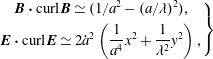 $$\begin{eqnarray}\left.\begin{array}{@{}c@{}}\boldsymbol{B}\boldsymbol{\cdot }\text{curl}\,\boldsymbol{B}\simeq (1/a^{2}-(a/\unicode[STIX]{x1D706})^{2}),\\[4.0pt] \boldsymbol{E}\boldsymbol{\cdot }\text{curl}\,\boldsymbol{E}\simeq 2{\dot{a}}^{2}\left({\displaystyle \frac{1}{a^{4}}}x^{2}+{\displaystyle \frac{1}{\unicode[STIX]{x1D706}^{2}}}y^{2}\right),\end{array}\right\}\end{eqnarray}$$
and the Maxwell equation reduces to
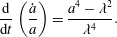 $$\begin{eqnarray}\frac{\text{d}}{\text{d}t}\left(\frac{{\dot{a}}}{a}\right)=\frac{a^{4}-\unicode[STIX]{x1D706}^{2}}{\unicode[STIX]{x1D706}^{4}}.\end{eqnarray}$$
Given
 $a(t)$
the electromagnetic field can be found via
$a(t)$
the electromagnetic field can be found via
 $$\begin{eqnarray}\left.\begin{array}{@{}c@{}}\boldsymbol{B}=\left({\displaystyle \frac{ya^{2}}{\unicode[STIX]{x1D706}^{2}}},{\displaystyle \frac{x}{a^{2}}},1\right),\\[10.0pt] \boldsymbol{E}=\left(y,x,-{\displaystyle \frac{x^{2}\unicode[STIX]{x1D706}^{2}+y^{2}a^{4}}{\unicode[STIX]{x1D706}^{2}a^{2}}}\right){\displaystyle \frac{{\dot{a}}}{a}}.\end{array}\right\}\end{eqnarray}$$
Solutions of (2.8) show that ‘the sqeezinees’ parameter
 $a(t)$
has a finite time singularity for
$a(t)$
has a finite time singularity for
 $\unicode[STIX]{x1D706}<1$
: in finite time
$\unicode[STIX]{x1D706}<1$
: in finite time
 $a$
becomes infinite, figure 1.
$a$
becomes infinite, figure 1.
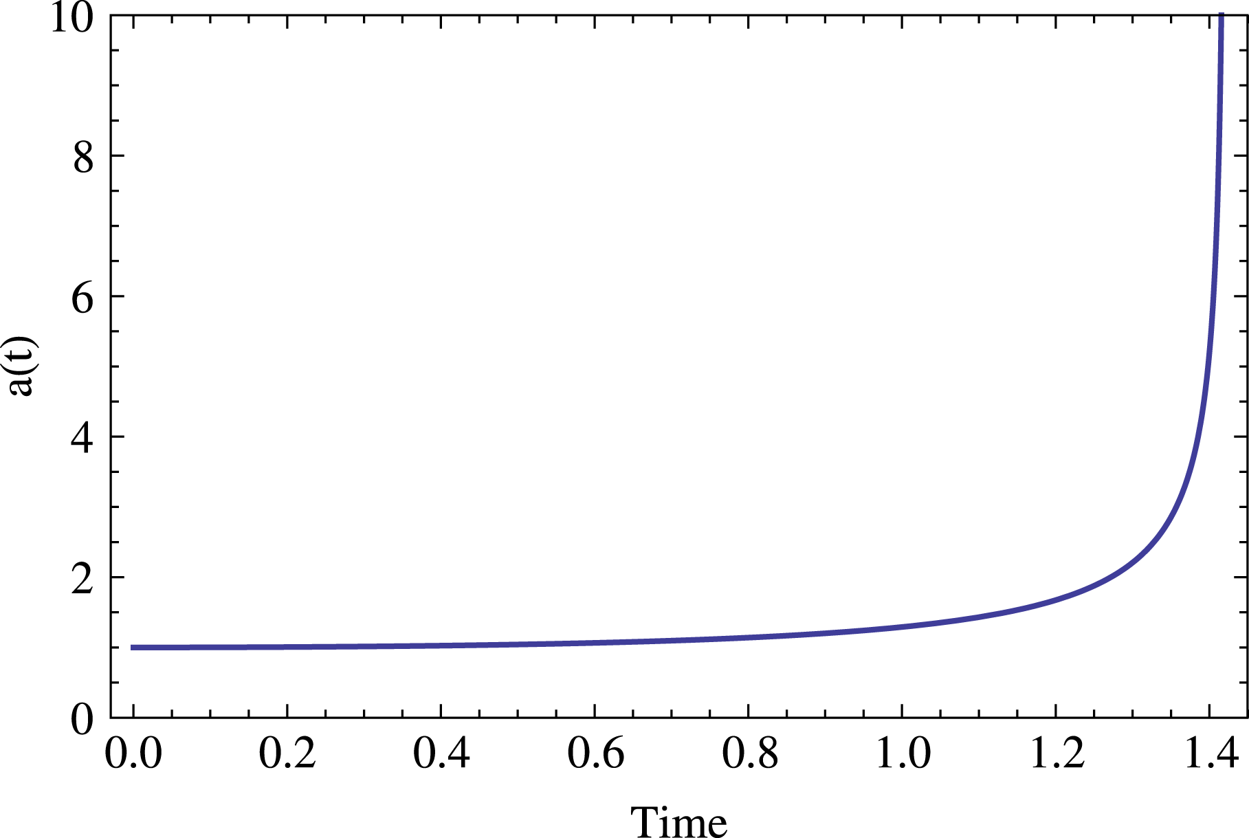
An example of the evolution of the parameter
 $a(t)$
, equation (2.8). Initially an X-point is squeezed by ten per cent,
$a(t)$
, equation (2.8). Initially an X-point is squeezed by ten per cent,
 $\unicode[STIX]{x1D706}=0.9$
, parameter
$\unicode[STIX]{x1D706}=0.9$
, parameter
 ${\mathcal{A}}=1$
. Evolution occurs on the dynamical time scale, until a singularity at
${\mathcal{A}}=1$
. Evolution occurs on the dynamical time scale, until a singularity at
 $t=1.42$
, so that the fast growing stage of the collapse proceeds much quicker.
$t=1.42$
, so that the fast growing stage of the collapse proceeds much quicker.
(For
 $\unicode[STIX]{x1D706}>1$
in finite time
$\unicode[STIX]{x1D706}>1$
in finite time
 $a$
becomes zero, so that
$a$
becomes zero, so that
 $b$
becomes infinite.) Thus, we have generalized the classic solution of Imshennik & Syrovatskiǐ (Reference Imshennik and Syrovatskiǐ1967) to the case of force-free plasma. At the moment when one of the parameters
$b$
becomes infinite.) Thus, we have generalized the classic solution of Imshennik & Syrovatskiǐ (Reference Imshennik and Syrovatskiǐ1967) to the case of force-free plasma. At the moment when one of the parameters
 $a$
or
$a$
or
 $b$
becomes zero, the current sheet forms, see figure 2
Footnote
2
.
$b$
becomes zero, the current sheet forms, see figure 2
Footnote
2
.
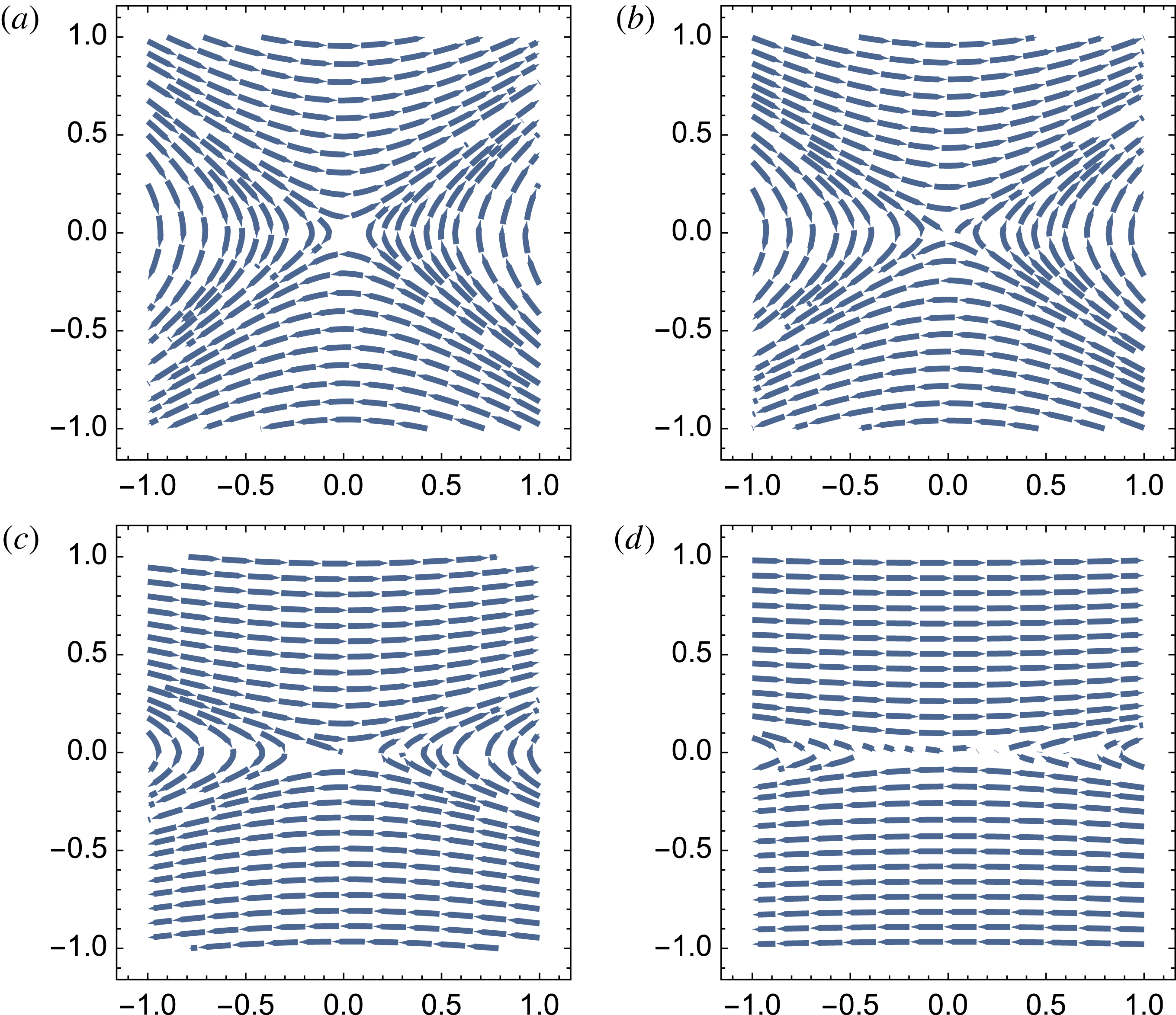
Structure of the magnetic field in the
 $x{-}y$
plane during X-point collapse in force-free plasma. The initial configuration on (a,c) is slightly ‘squeezed’,
$x{-}y$
plane during X-point collapse in force-free plasma. The initial configuration on (a,c) is slightly ‘squeezed’,
 $\unicode[STIX]{x1D706}=0.9$
. On a dynamical time scale the X-point collapses to form a current sheet, (b,d). The structure of the electric field in the
$\unicode[STIX]{x1D706}=0.9$
. On a dynamical time scale the X-point collapses to form a current sheet, (b,d). The structure of the electric field in the
 $x{-}y$
plane does not change during the collapse and qualitatively resembles the
$x{-}y$
plane does not change during the collapse and qualitatively resembles the
 $t=0$
configuration of the magnetic field.
$t=0$
configuration of the magnetic field.
For small initial deformation of the X-point,
 $\unicode[STIX]{x1D706}=1-\unicode[STIX]{x1D716}$
where
$\unicode[STIX]{x1D706}=1-\unicode[STIX]{x1D716}$
where
 $\unicode[STIX]{x1D716}\ll 1$
is a small parameter. Given the initial conditions
$\unicode[STIX]{x1D716}\ll 1$
is a small parameter. Given the initial conditions
 $a(0)=1$
,
$a(0)=1$
,
 ${\dot{a}}(0)=0$
, the corresponding asymptotic solution of (2.8) is
${\dot{a}}(0)=0$
, the corresponding asymptotic solution of (2.8) is
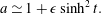 $$\begin{eqnarray}a\simeq 1+\unicode[STIX]{x1D716}\sinh ^{2}t.\end{eqnarray}$$
This solution is not uniform as at
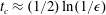 $t_{c}\approx (1/2)\ln (1/\unicode[STIX]{x1D716})$
the perturbation becomes large. This sets the typical time scale of the X-point collapse. Since the unit time is
$t_{c}\approx (1/2)\ln (1/\unicode[STIX]{x1D716})$
the perturbation becomes large. This sets the typical time scale of the X-point collapse. Since the unit time is
 $L/c$
, where
$L/c$
, where
 $L$
is the distance where the guide field has the same strength as the in-plane magnetic field of the X-point, it is obvious that with vanishing guide field the collapse occurs instantaneously.
$L$
is the distance where the guide field has the same strength as the in-plane magnetic field of the X-point, it is obvious that with vanishing guide field the collapse occurs instantaneously.
In this solution, the electric field grows as
 $$\begin{eqnarray}\boldsymbol{E}\simeq \unicode[STIX]{x1D716}(y,x,-x^{2}+y^{2})\sinh 2t,\end{eqnarray}$$
indicating that at
 $t\approx t_{c}$
it may become comparable to the magnetic field. Importantly, the ratio of the electric field, dominated mostly by
$t\approx t_{c}$
it may become comparable to the magnetic field. Importantly, the ratio of the electric field, dominated mostly by
 $E_{z}$
, to the magnetic field, dominated at late times by
$E_{z}$
, to the magnetic field, dominated at late times by
 $B_{x}$
, increases with
$B_{x}$
, increases with
 $y$
(distances away from the newly forming current sheet),
$y$
(distances away from the newly forming current sheet),
 $$\begin{eqnarray}\frac{E_{z}}{B_{x}}\propto y.\end{eqnarray}$$
Thus, the analytical model predicts that the electric field becomes of the order of the magnetic field in a large domain, not only close to the null line. This is confirmed by numerical simulations, see §§ 3 and 4.
2.3 Charge starvation during collapse
During the X-point collapse the electromagnetic fields and currents experience a sharp growth, especially near the null line. The current density at the null line grows exponentially at early times,
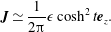 $$\begin{eqnarray}\boldsymbol{J}\simeq \frac{1}{2\unicode[STIX]{x03C0}}\unicode[STIX]{x1D716}\cosh ^{2}t\boldsymbol{e}_{z}.\end{eqnarray}$$
Since
 $a\rightarrow \infty$
during collapse, the current density similarly increases during the collapse. As the parameter
$a\rightarrow \infty$
during collapse, the current density similarly increases during the collapse. As the parameter
 $a$
grows, this imposes larger and larger demand on the velocity of the current-carrying particles. But the maximum current density cannot exceed
$a$
grows, this imposes larger and larger demand on the velocity of the current-carrying particles. But the maximum current density cannot exceed
 $J_{z}<2en_{e}c$
. Thus, if
$J_{z}<2en_{e}c$
. Thus, if
 $$\begin{eqnarray}a(t)>\sqrt{\frac{L}{\unicode[STIX]{x1D6FF}}}\frac{1}{\unicode[STIX]{x1D70E}^{1/4}}\end{eqnarray}$$
the current becomes charge starved (here,
 $\unicode[STIX]{x1D6FF}=c/\unicode[STIX]{x1D714}_{p}$
,
$\unicode[STIX]{x1D6FF}=c/\unicode[STIX]{x1D714}_{p}$
,
 $\unicode[STIX]{x1D714}_{p}^{2}=4\unicode[STIX]{x03C0}n_{e}e^{2}/m_{e}$
are plasma skin depth and plasma frequencies). This charge starvation leads to efficient linear particle acceleration. This is the one of the key points of the model.
$\unicode[STIX]{x1D714}_{p}^{2}=4\unicode[STIX]{x03C0}n_{e}e^{2}/m_{e}$
are plasma skin depth and plasma frequencies). This charge starvation leads to efficient linear particle acceleration. This is the one of the key points of the model.
The analytical estimates given above are in agreement with PIC simulations, § 4. Our typical runs have
 $L/\unicode[STIX]{x1D6FF}\sim$
hundreds, while the magnetization parameter at the outer scale is
$L/\unicode[STIX]{x1D6FF}\sim$
hundreds, while the magnetization parameter at the outer scale is
 $\unicode[STIX]{x1D70E}\sim$
thousands. Thus we expect that the charge starvation occurs approximately at
$\unicode[STIX]{x1D70E}\sim$
thousands. Thus we expect that the charge starvation occurs approximately at
 $a\sim$
few – when the opening of the X-point becomes tens of degrees.
$a\sim$
few – when the opening of the X-point becomes tens of degrees.
3 Force-free simulations
The approximate nature of the analytical solution described in the previous section invites a numerical study of the X-point collapse in the force-free approximation. To this aim we use a computer code, which solves Maxwell equations supplemented with the Ohm law
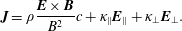 $$\begin{eqnarray}\boldsymbol{J}=\unicode[STIX]{x1D70C}\frac{\boldsymbol{E}\times \boldsymbol{B}}{B^{2}}c+\unicode[STIX]{x1D705}_{\Vert }\boldsymbol{E}_{\Vert }+\unicode[STIX]{x1D705}_{\bot }\boldsymbol{E}_{\bot }.\end{eqnarray}$$
In this equation, the first term represents the drift current (cf. (2.1)), whereas the second and third terms introduce conductivity along and perpendicular to the magnetic field respectively. The parallel conductivity
 $\unicode[STIX]{x1D705}_{\Vert }$
is always set to a high value in order to quickly drive the solution towards the force-free state where
$\unicode[STIX]{x1D705}_{\Vert }$
is always set to a high value in order to quickly drive the solution towards the force-free state where
 $E_{\Vert }=0$
. The perpendicular conductivity
$E_{\Vert }=0$
. The perpendicular conductivity
 $\unicode[STIX]{x1D705}_{\bot }$
is normally set to zero. Only when
$\unicode[STIX]{x1D705}_{\bot }$
is normally set to zero. Only when
 $E>B$
it is set to a high value in order to quickly obtain
$E>B$
it is set to a high value in order to quickly obtain
 $E\leqslant B$
. These two terms also introduce dissipation, which becomes significant inside current sheets. This phenomenological approach adopted from resistive MHD becomes inaccurate inside collisionless current sheets where plasma effects determine the electric current and dissipation. This becomes manifest when we compare our force-free (FF) and PIC simulations. The numerical scheme is described in details in Komissarov et al. (Reference Komissarov, Barkov and Lyutikov2007). It is second order in space and time, with the source terms treated using the strand-splitting algorithm. The method of generalized Lagrange multiplier is employed to keep the magnetic field almost divergence free.
$E\leqslant B$
. These two terms also introduce dissipation, which becomes significant inside current sheets. This phenomenological approach adopted from resistive MHD becomes inaccurate inside collisionless current sheets where plasma effects determine the electric current and dissipation. This becomes manifest when we compare our force-free (FF) and PIC simulations. The numerical scheme is described in details in Komissarov et al. (Reference Komissarov, Barkov and Lyutikov2007). It is second order in space and time, with the source terms treated using the strand-splitting algorithm. The method of generalized Lagrange multiplier is employed to keep the magnetic field almost divergence free.
The X-point collapse simulations are initialized with the magnetic field described by (2.9), with parameters
 $a=1$
,
$a=1$
,
 $\unicode[STIX]{x1D706}=\sqrt{0.5}$
, and vanishing electric field. In the first simulations, we focus on the time scale corresponding to the onset of the X-point collapse,
$\unicode[STIX]{x1D706}=\sqrt{0.5}$
, and vanishing electric field. In the first simulations, we focus on the time scale corresponding to the onset of the X-point collapse,
 $t<1$
. We use a two-dimensional uniform Cartesian grid with
$t<1$
. We use a two-dimensional uniform Cartesian grid with
 $400\times 400$
cells covering the
$400\times 400$
cells covering the
 $x{-}y$
domain
$x{-}y$
domain
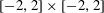 $[-2,2]\times [-2,2]$
and impose the zero-gradient boundary conditions. Such boundary conditions inevitably lead to an additional perturbation of the X-point configuration near the boundaries, which send waves propagate inside the computational domain with the speed of light. However, these waves do not reach the central area of interest,
$[-2,2]\times [-2,2]$
and impose the zero-gradient boundary conditions. Such boundary conditions inevitably lead to an additional perturbation of the X-point configuration near the boundaries, which send waves propagate inside the computational domain with the speed of light. However, these waves do not reach the central area of interest,
 $[-1,1]\times [-1,1]$
, on the simulation time scale. Given the rather strong initial compression of the X-point, with
$[-1,1]\times [-1,1]$
, on the simulation time scale. Given the rather strong initial compression of the X-point, with
 $\unicode[STIX]{x1D716}\approx 0.4$
, the collapse time predicted by the theory is
$\unicode[STIX]{x1D716}\approx 0.4$
, the collapse time predicted by the theory is
 $t_{c}\approx 0.44$
.
$t_{c}\approx 0.44$
.
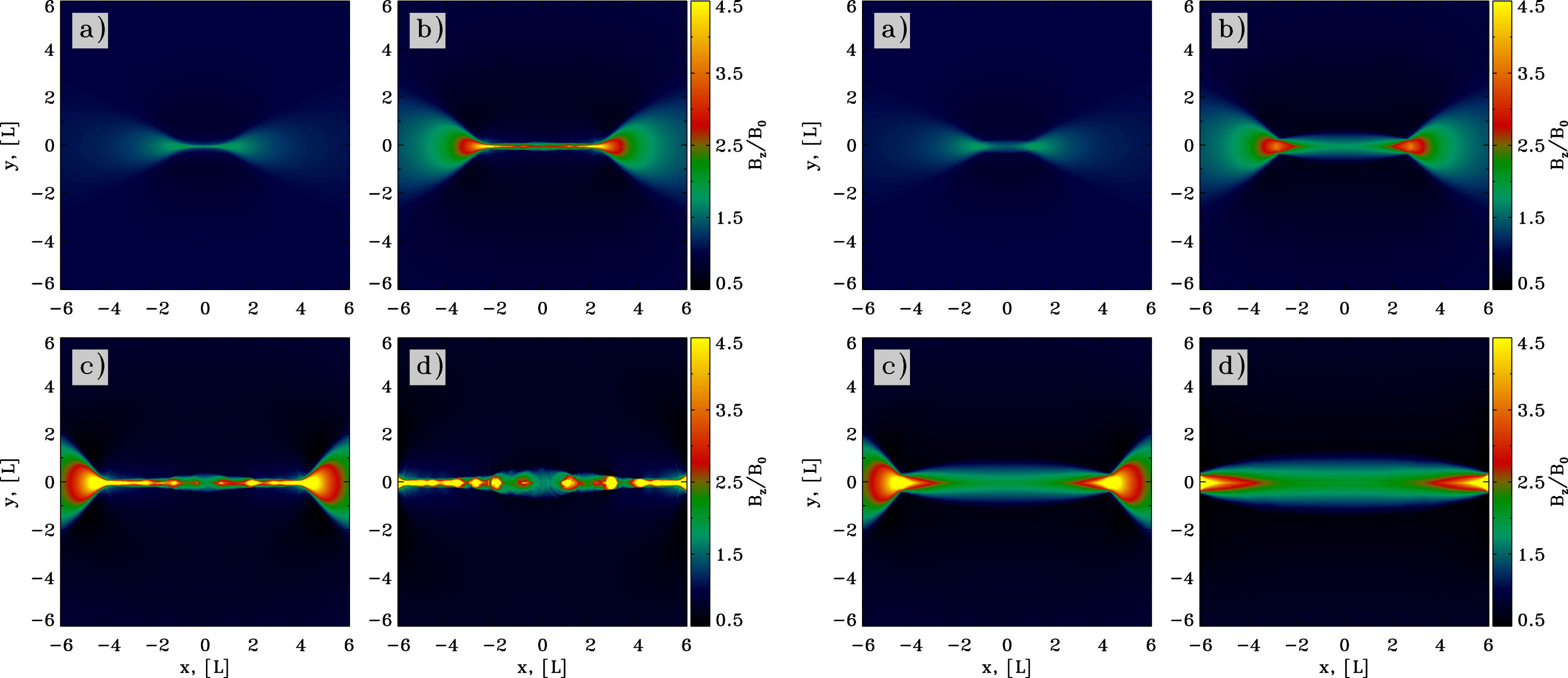
Figure 3 shows the magnetic field lines and the strength of the guide field
 $B_{0}$
in the central area at four instances during the time interval
$B_{0}$
in the central area at four instances during the time interval
 $[0,1]$
. In accord with the theory, the degree of the X-point compression increases with time and becomes visible to naked eye at
$[0,1]$
. In accord with the theory, the degree of the X-point compression increases with time and becomes visible to naked eye at
 $t\simeq t_{c}$
. However, the figure also shows that on this time scale the numerical solution begins to deviate strongly from the analytical one. Indeed, the distribution of the guide field becomes significantly non-uniform – it gets compressed in the plane of collapse (
$t\simeq t_{c}$
. However, the figure also shows that on this time scale the numerical solution begins to deviate strongly from the analytical one. Indeed, the distribution of the guide field becomes significantly non-uniform – it gets compressed in the plane of collapse (
 $y=0$
).
$y=0$
).
Initial phase of a solitary X-point collapse in FF simulations. The plots show
 $B_{z}$
at
$B_{z}$
at
 $t=0.25$
, 0.5, 0.75 and 1. These plots are to be compared with figure 6, which shows the results of PIC simulations with the same initial set-up.
$t=0.25$
, 0.5, 0.75 and 1. These plots are to be compared with figure 6, which shows the results of PIC simulations with the same initial set-up.

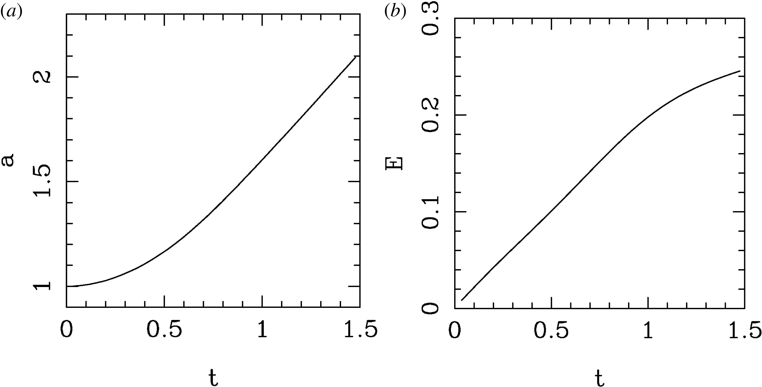
This is confirmed in figure 4, which shows the evolution of the compression parameter
 $a$
and the electric field strength, both computed at the point
$a$
and the electric field strength, both computed at the point
 $(x,y)=(-0.1,0.1)$
. In order to measure the local value of
$(x,y)=(-0.1,0.1)$
. In order to measure the local value of
 $a$
, we use (2.9), which yields
$a$
, we use (2.9), which yields
 $$\begin{eqnarray}a(t)=\unicode[STIX]{x1D706}^{1/2}(xB_{x}/yB_{y})^{1/4}.\end{eqnarray}$$
One can see that although the characteristic time scale is close to
 $t_{c}$
, the numerical solution does not quite follow the analytical one. This is expected as the analytic solution is only accurate for
$t_{c}$
, the numerical solution does not quite follow the analytical one. This is expected as the analytic solution is only accurate for
 $t\ll t_{c}$
. The PIC simulations, which are described in the next section, yield very similar results.
$t\ll t_{c}$
. The PIC simulations, which are described in the next section, yield very similar results.
Evolution of the parameter
 $a(t)$
(a) and the total electric field strength
$a(t)$
(a) and the total electric field strength
 $E(t)$
(b) during the initial phase. The measurements are taken at the point
$E(t)$
(b) during the initial phase. The measurements are taken at the point
 $(x,y)=(-0.1,0.1)$
. The analytical solution gives the collapse time
$(x,y)=(-0.1,0.1)$
. The analytical solution gives the collapse time
 $\unicode[STIX]{x1D70F}=1.0$
. These results are sufficiently close, considering the fact that (2.8) was derived as an asymptotic limit near the
$\unicode[STIX]{x1D70F}=1.0$
. These results are sufficiently close, considering the fact that (2.8) was derived as an asymptotic limit near the
 $X$
-point.
$X$
-point.
Long-term evolution of stressed solitary X-point in FF simulations. (a) Shows the
 $B_{z}$
component of the magnetic field. (b) Shows
$B_{z}$
component of the magnetic field. (b) Shows
 $1-E^{2}/B^{2}$
(colour) and magnetic field lines The plots show the numerical solution at
$1-E^{2}/B^{2}$
(colour) and magnetic field lines The plots show the numerical solution at
 $t=1.5$
, 3, 4.5 and 6. PIC simulations for the same initial configuration are shown in figures 9 and 10.
$t=1.5$
, 3, 4.5 and 6. PIC simulations for the same initial configuration are shown in figures 9 and 10.

In order to study the evolution of the X-point at
 $t>t_{c}$
, we repeated the simulations on in a larger computational domain,
$t>t_{c}$
, we repeated the simulations on in a larger computational domain,
 $[-10,10]\times [-10,10]$
with
$[-10,10]\times [-10,10]$
with
 $800\times 800$
cells. The results are illustrated in figure 5. One can see that at
$800\times 800$
cells. The results are illustrated in figure 5. One can see that at
 $t\approx t_{c}$
the X-point turns into a current sheet, bounded by two Y-points. The separation between these Y-points increase with approximately twice the speed of light. For
$t\approx t_{c}$
the X-point turns into a current sheet, bounded by two Y-points. The separation between these Y-points increase with approximately twice the speed of light. For
 $t\gg t_{c}$
the solution begins to exhibits a self-similar evolution, which is expected as the only characteristic length scale of this problem is
$t\gg t_{c}$
the solution begins to exhibits a self-similar evolution, which is expected as the only characteristic length scale of this problem is
 $l=1$
. Ahead of each of Y-point there are bow-shaped regions where the drift speed is very close to
$l=1$
. Ahead of each of Y-point there are bow-shaped regions where the drift speed is very close to
 $c$
and
$c$
and
 $E\simeq B$
. Inside the current sheet the force-free approximation breaks down completely as the electric field strength tends to exceed that of the magnetic field. Given our prescription for the resistivity some of the electromagnetic field disappears inside the current sheet without a trace. In order to capture the evolution of this current sheet properly particles must be reintroduced into the system, which done in the PIC simulations described in the next section.
$E\simeq B$
. Inside the current sheet the force-free approximation breaks down completely as the electric field strength tends to exceed that of the magnetic field. Given our prescription for the resistivity some of the electromagnetic field disappears inside the current sheet without a trace. In order to capture the evolution of this current sheet properly particles must be reintroduced into the system, which done in the PIC simulations described in the next section.
4 PIC simulations
4.1 Overall principles and parameters of PIC simulations
The most fundamental method for simulating the kinetic dynamics of a reconnecting plasma involves the use of particle-in-cell codes, that evolve the discretized equations of electrodynamics – Maxwell’s equations and the Lorentz force law (Hockney & Eastwood Reference Hockney and Eastwood1981; Birdsall & Langdon Reference Birdsall and Langdon1991). PIC codes can model astrophysical plasmas from first principles, as a collection of charged macro-particles – each representing many physical particles – that are moved by integration of the Lorentz forceFootnote 3 . The electric currents associated with the macro-particles are deposited on a grid, where Maxwell’s equations are discretized. Electromagnetic fields are then advanced via Maxwell’s equations, with particle currents as the source term. Finally, the updated fields are extrapolated to the particle locations and used for the computation of the Lorentz force, so the loop is closed self-consistently.
We study the collapse of a solitary X-point with 2-D PIC simulations, employing the massively parallel electromagnetic PIC code TRISTAN-MP (Buneman Reference Buneman1993; Spitkovsky Reference Spitkovsky, Bulik, Rudak and Madejski2005). Our computational domain is a square in the
 $x{-}y$
plane, which is initialized with a uniform density of cold electron–positron plasma (the composition of pulsar wind nebulae is inferred to have negligible ion/proton component). The simulation is initialized with a vanishing electric field and with the magnetic field appropriate for a stressed X-point collapse (see (2.9)) with
$x{-}y$
plane, which is initialized with a uniform density of cold electron–positron plasma (the composition of pulsar wind nebulae is inferred to have negligible ion/proton component). The simulation is initialized with a vanishing electric field and with the magnetic field appropriate for a stressed X-point collapse (see (2.9)) with
 $\unicode[STIX]{x1D706}=1/\sqrt{2}$
, for direct comparison with the force-free results described aboveFootnote
4
. The stressed X-point configuration would require a particle current in the direction perpendicular to the simulation plane, to sustain the curl of the field (which, on the other hand, is absent in the case of an unstressed X-point). In our set-up, the computational particles are initialized at rest, but such electric current gets self-consistently built up within a few time steps. At the boundaries of the box, the field is reset at every time step to the initial configuration. This leads to an artificial deformation of the self-consistent X-point evolution which propagates from the boundaries toward the centre at the speed of light. However, our domain is chosen to be large enough such that this perturbation does not reach the central area of interest within the timespan covered by our simulations.
$\unicode[STIX]{x1D706}=1/\sqrt{2}$
, for direct comparison with the force-free results described aboveFootnote
4
. The stressed X-point configuration would require a particle current in the direction perpendicular to the simulation plane, to sustain the curl of the field (which, on the other hand, is absent in the case of an unstressed X-point). In our set-up, the computational particles are initialized at rest, but such electric current gets self-consistently built up within a few time steps. At the boundaries of the box, the field is reset at every time step to the initial configuration. This leads to an artificial deformation of the self-consistent X-point evolution which propagates from the boundaries toward the centre at the speed of light. However, our domain is chosen to be large enough such that this perturbation does not reach the central area of interest within the timespan covered by our simulations.
We perform two sets of simulations. First, we explore the physics at relatively early times with a 2-D Cartesian grid of
 $32\,768\times 32\,768$
cells. The spatial resolution is such that the plasma skin depth
$32\,768\times 32\,768$
cells. The spatial resolution is such that the plasma skin depth
 $c/\unicode[STIX]{x1D714}_{p}$
is resolved with 10 cellsFootnote
5
. The unit length is
$c/\unicode[STIX]{x1D714}_{p}$
is resolved with 10 cellsFootnote
5
. The unit length is
 $L=800c/\unicode[STIX]{x1D714}_{p}$
, so that the domain size is a square with
$L=800c/\unicode[STIX]{x1D714}_{p}$
, so that the domain size is a square with
 $\simeq 4L$
on each side. The physical region of interest is the central
$\simeq 4L$
on each side. The physical region of interest is the central
 $2L\times 2L$
square. The simulation is evolved up to
$2L\times 2L$
square. The simulation is evolved up to
 ${\sim}L/c$
, so that the artificial perturbation driven by the boundaries does not affect the region of interest. In a second set of simulations, we explore the physics at late times, with a 2-D Cartesian box of
${\sim}L/c$
, so that the artificial perturbation driven by the boundaries does not affect the region of interest. In a second set of simulations, we explore the physics at late times, with a 2-D Cartesian box of
 $40\,960\times 40\,960$
cells, with spatial resolution
$40\,960\times 40\,960$
cells, with spatial resolution
 $c/\unicode[STIX]{x1D714}_{p}=1.25$
cells. With the unit length still being
$c/\unicode[STIX]{x1D714}_{p}=1.25$
cells. With the unit length still being
 $L=800c/\unicode[STIX]{x1D714}_{p}$
, the overall system is a square of
$L=800c/\unicode[STIX]{x1D714}_{p}$
, the overall system is a square of
 $\simeq 41L$
on each side. At early times, the evolution is entirely consistent with the results of the first set of simulations described above, which suggests that a spatial resolution of
$\simeq 41L$
on each side. At early times, the evolution is entirely consistent with the results of the first set of simulations described above, which suggests that a spatial resolution of
 $c/\unicode[STIX]{x1D714}_{p}=1.25$
cells is still sufficient to capture the relevant physics (more generally, we have checked for numerical convergence from
$c/\unicode[STIX]{x1D714}_{p}=1.25$
cells is still sufficient to capture the relevant physics (more generally, we have checked for numerical convergence from
 $c/\unicode[STIX]{x1D714}_{p}=1.25$
cells up to
$c/\unicode[STIX]{x1D714}_{p}=1.25$
cells up to
 $c/\unicode[STIX]{x1D714}_{p}=20$
cells). We follow the large-scale system up to
$c/\unicode[STIX]{x1D714}_{p}=20$
cells). We follow the large-scale system up to
 ${\sim}6L/c$
, so that the evolution of the physical region at the centre stays unaffected by the boundary conditions.
${\sim}6L/c$
, so that the evolution of the physical region at the centre stays unaffected by the boundary conditions.
For both sets of simulations, each cell is initialized with two macro-positrons and two macro-electrons (with a small thermal dispersion of
 $kT/mc^{2}=10^{-4}$
). Hence the initial plasma density distribution is uniform, whereas the magnetic field is not. This leads to a non-uniform magnetization, which increases with the distance from the centre line of the X-point. We have checked that our results are the same when using up to 24 particles per cell. In order to reduce noise in the simulation, we filter the electric current deposited onto the grid by the particles, effectively mimicking the effect of a larger number of particles per cell (Spitkovsky Reference Spitkovsky, Bulik, Rudak and Madejski2005; Belyaev Reference Belyaev2015).
$kT/mc^{2}=10^{-4}$
). Hence the initial plasma density distribution is uniform, whereas the magnetic field is not. This leads to a non-uniform magnetization, which increases with the distance from the centre line of the X-point. We have checked that our results are the same when using up to 24 particles per cell. In order to reduce noise in the simulation, we filter the electric current deposited onto the grid by the particles, effectively mimicking the effect of a larger number of particles per cell (Spitkovsky Reference Spitkovsky, Bulik, Rudak and Madejski2005; Belyaev Reference Belyaev2015).
We explore the dependence of our results on two physical parameters, namely the strength of the guide field and the flow magnetization. In the simulations with guide field, the guide field is initially uniform and its strength is chosen to be equal to that of the unstressed in-plane field of the X-point at the unit distance from the origin. This case allows for a direct comparison with analytical theory and force-free results. We also studied the case without a guide field. This case will be relevant for our investigation of the collapse of Arnold–Beltrami–Childress (ABC) structures, considered in the second paper of this series. There, we will demonstrate that particle acceleration is most efficient at null points, i.e. where both the in-plane fields and the out-of-plane guide field vanish.
In addition to the guide field strength, we investigate the dependence of our results on the flow magnetization, which for a cold electron–positron plasma reduces to
 $\unicode[STIX]{x1D70E}=B^{2}/4\unicode[STIX]{x03C0}mnc^{2}$
. The physics of X-point collapse has been widely studied in the literature with PIC simulations (Tsiklauri & Haruki Reference Tsiklauri and Haruki2007, Reference Tsiklauri and Haruki2008; Graf von der Pahlen & Tsiklauri Reference Graf von der Pahlen and Tsiklauri2014; von der Pahlen & Tsiklauri Reference von der Pahlen and Tsiklauri2014), but only in the non-relativistic regime
$\unicode[STIX]{x1D70E}=B^{2}/4\unicode[STIX]{x03C0}mnc^{2}$
. The physics of X-point collapse has been widely studied in the literature with PIC simulations (Tsiklauri & Haruki Reference Tsiklauri and Haruki2007, Reference Tsiklauri and Haruki2008; Graf von der Pahlen & Tsiklauri Reference Graf von der Pahlen and Tsiklauri2014; von der Pahlen & Tsiklauri Reference von der Pahlen and Tsiklauri2014), but only in the non-relativistic regime
 $\unicode[STIX]{x1D70E}\ll 1$
. To the best of our knowledge, our investigation is the first to focus on the relativistic regime
$\unicode[STIX]{x1D70E}\ll 1$
. To the best of our knowledge, our investigation is the first to focus on the relativistic regime
 $\unicode[STIX]{x1D70E}\gg 1$
, which is appropriate for relativistic astrophysical outflows. Since the in-plane field of the initial configuration grows linearly with distance from the centre line and the plasma density is uniform, the corresponding magnetization increases quadratically with the distance in the case without guide field and somewhat slower when the guide field is included. For definiteness, we opted to parametrize our runs via the initial value
$\unicode[STIX]{x1D70E}\gg 1$
, which is appropriate for relativistic astrophysical outflows. Since the in-plane field of the initial configuration grows linearly with distance from the centre line and the plasma density is uniform, the corresponding magnetization increases quadratically with the distance in the case without guide field and somewhat slower when the guide field is included. For definiteness, we opted to parametrize our runs via the initial value
 $\unicode[STIX]{x1D70E}_{L}$
of plasma magnetization at the unit distance
$\unicode[STIX]{x1D70E}_{L}$
of plasma magnetization at the unit distance
 $L$
from the origin (along the unstressed
$L$
from the origin (along the unstressed
 $x$
direction), measured only with the in-plane fields (so, excluding the guide field). We explore three values of
$x$
direction), measured only with the in-plane fields (so, excluding the guide field). We explore three values of
 $\unicode[STIX]{x1D70E}_{L}$
:
$\unicode[STIX]{x1D70E}_{L}$
:
 $4\times 10^{2}$
,
$4\times 10^{2}$
,
 $4\times 10^{3}$
and
$4\times 10^{3}$
and
 $4\times 10^{4}$
.
$4\times 10^{4}$
.
Initial phase of an X-point collapse in PIC simulations with guide field, for two different magnetizations:
 $\unicode[STIX]{x1D70E}_{L}=4\times 10^{3}$
(left) and
$\unicode[STIX]{x1D70E}_{L}=4\times 10^{3}$
(left) and
 $\unicode[STIX]{x1D70E}_{L}=4\times 10^{4}$
(right). The plots show the out-of-plane field
$\unicode[STIX]{x1D70E}_{L}=4\times 10^{4}$
(right). The plots show the out-of-plane field
 $B_{z}$
at
$B_{z}$
at
 $ct/L=0.25$
, 0.5, 0.75 and 1, from (a–d). This figure corresponds to figure 3, which shows the results of force-free simulations.
$ct/L=0.25$
, 0.5, 0.75 and 1, from (a–d). This figure corresponds to figure 3, which shows the results of force-free simulations.
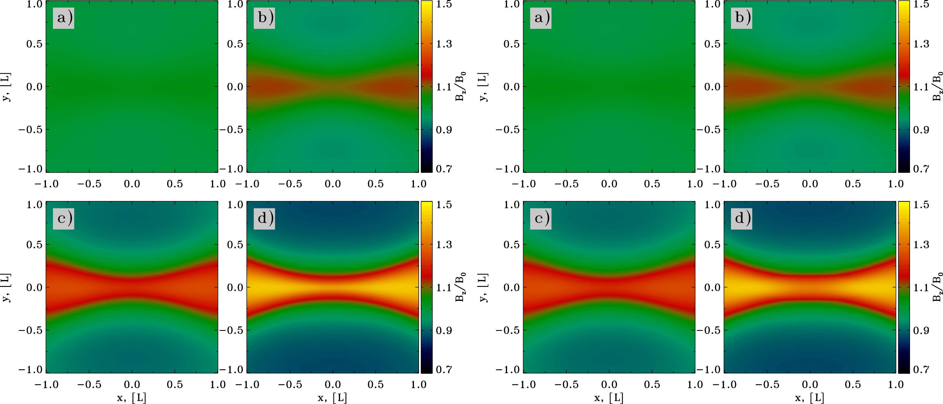
4.2 Stressed X-point collapse with guide field
Figure 6 shows the initial phase (
 $ct/L\leqslant 1$
) of the collapse of a solitary X-point in PIC simulations with
$ct/L\leqslant 1$
) of the collapse of a solitary X-point in PIC simulations with
 $\unicode[STIX]{x1D706}=1/\sqrt{2}$
and with guide field, for two different magnetizations:
$\unicode[STIX]{x1D706}=1/\sqrt{2}$
and with guide field, for two different magnetizations:
 $\unicode[STIX]{x1D70E}_{L}=4\times 10^{3}$
(left) and
$\unicode[STIX]{x1D70E}_{L}=4\times 10^{3}$
(left) and
 $\unicode[STIX]{x1D70E}_{L}=4\times 10^{4}$
(right). The expected rapid collapse of the squeezed X-point is clearly visible, and in excellent agreement with the 2-D results of force-free simulations, as shown in figure 3. The out-of-plane magnetic field
$\unicode[STIX]{x1D70E}_{L}=4\times 10^{4}$
(right). The expected rapid collapse of the squeezed X-point is clearly visible, and in excellent agreement with the 2-D results of force-free simulations, as shown in figure 3. The out-of-plane magnetic field
 $B_{z}$
is compressed toward the
$B_{z}$
is compressed toward the
 $y=0$
plane, in agreement with the force-free results, but in apparent contradiction with the analytical solution, that assumed no evolution of the guide field. The 2-D pattern of
$y=0$
plane, in agreement with the force-free results, but in apparent contradiction with the analytical solution, that assumed no evolution of the guide field. The 2-D pattern of
 $B_{z}$
in PIC simulations is remarkably independent of the magnetization (compare left and right), for the early phases presented in figure 6.
$B_{z}$
in PIC simulations is remarkably independent of the magnetization (compare left and right), for the early phases presented in figure 6.
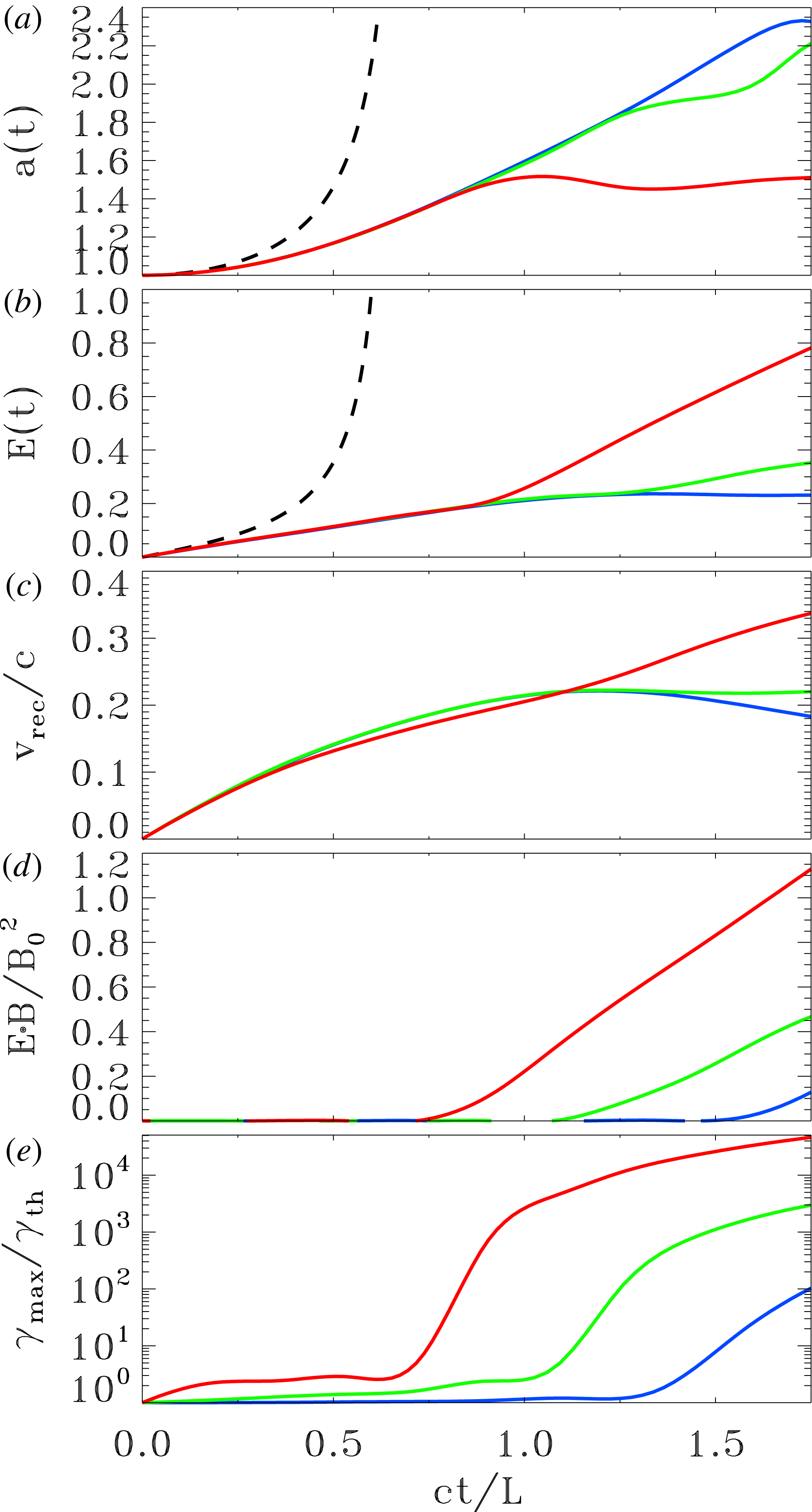
Temporal evolution of various quantities from PIC simulations of an X-point collapse with guide field, for three values of the magnetization:
 $\unicode[STIX]{x1D70E}_{L}=4\times 10^{2}$
(blue),
$\unicode[STIX]{x1D70E}_{L}=4\times 10^{2}$
(blue),
 $\unicode[STIX]{x1D70E}_{L}=4\times 10^{3}$
(green) and
$\unicode[STIX]{x1D70E}_{L}=4\times 10^{3}$
(green) and
 $\unicode[STIX]{x1D70E}_{L}=4\times 10^{4}$
(red). As a function of time, we plot: (a) the value of
$\unicode[STIX]{x1D70E}_{L}=4\times 10^{4}$
(red). As a function of time, we plot: (a) the value of
 $a(t)=\unicode[STIX]{x1D706}^{1/2}(B_{x}/B_{y})^{1/4}$
at the location
$a(t)=\unicode[STIX]{x1D706}^{1/2}(B_{x}/B_{y})^{1/4}$
at the location
 $(-0.1L,0.1L)$
, to be compared with the result of force-free simulations in figure 4(a) and with the analytical estimates (dashed line); (b) the value of the electric field strength
$(-0.1L,0.1L)$
, to be compared with the result of force-free simulations in figure 4(a) and with the analytical estimates (dashed line); (b) the value of the electric field strength
 $E(t)$
at the location
$E(t)$
at the location
 $(-0.1L,0.1L)$
in units of
$(-0.1L,0.1L)$
in units of
 $B_{0}$
, to be compared with the result of force-free simulations in figure 4(b) and with the analytical estimates (dashed line); (c), the reconnection rate, defined as the inflow speed along the
$B_{0}$
, to be compared with the result of force-free simulations in figure 4(b) and with the analytical estimates (dashed line); (c), the reconnection rate, defined as the inflow speed along the
 $y$
direction averaged over a square of side equal to
$y$
direction averaged over a square of side equal to
 $L$
around the central region; (d) the parameter
$L$
around the central region; (d) the parameter
 $\boldsymbol{E}\boldsymbol{\cdot }\boldsymbol{B}/B_{0}^{2}$
at the centre of the domain, which explicitly shows when the force-free condition
$\boldsymbol{E}\boldsymbol{\cdot }\boldsymbol{B}/B_{0}^{2}$
at the centre of the domain, which explicitly shows when the force-free condition
 $\boldsymbol{E}\boldsymbol{\cdot }\boldsymbol{B}=0$
is broken; (e) the maximum particle Lorentz factor
$\boldsymbol{E}\boldsymbol{\cdot }\boldsymbol{B}=0$
is broken; (e) the maximum particle Lorentz factor
 $\unicode[STIX]{x1D6FE}_{\max }$
(as defined in (4.1)), in units of the thermal value
$\unicode[STIX]{x1D6FE}_{\max }$
(as defined in (4.1)), in units of the thermal value
 $\unicode[STIX]{x1D6FE}_{\text{th}}\simeq 1+(\hat{\unicode[STIX]{x1D6FE}}-1)^{-1}kT/mc^{2}$
, which in this case of a cold plasma reduces to
$\unicode[STIX]{x1D6FE}_{\text{th}}\simeq 1+(\hat{\unicode[STIX]{x1D6FE}}-1)^{-1}kT/mc^{2}$
, which in this case of a cold plasma reduces to
 $\unicode[STIX]{x1D6FE}_{\text{th}}\simeq 1$
.
$\unicode[STIX]{x1D6FE}_{\text{th}}\simeq 1$
.
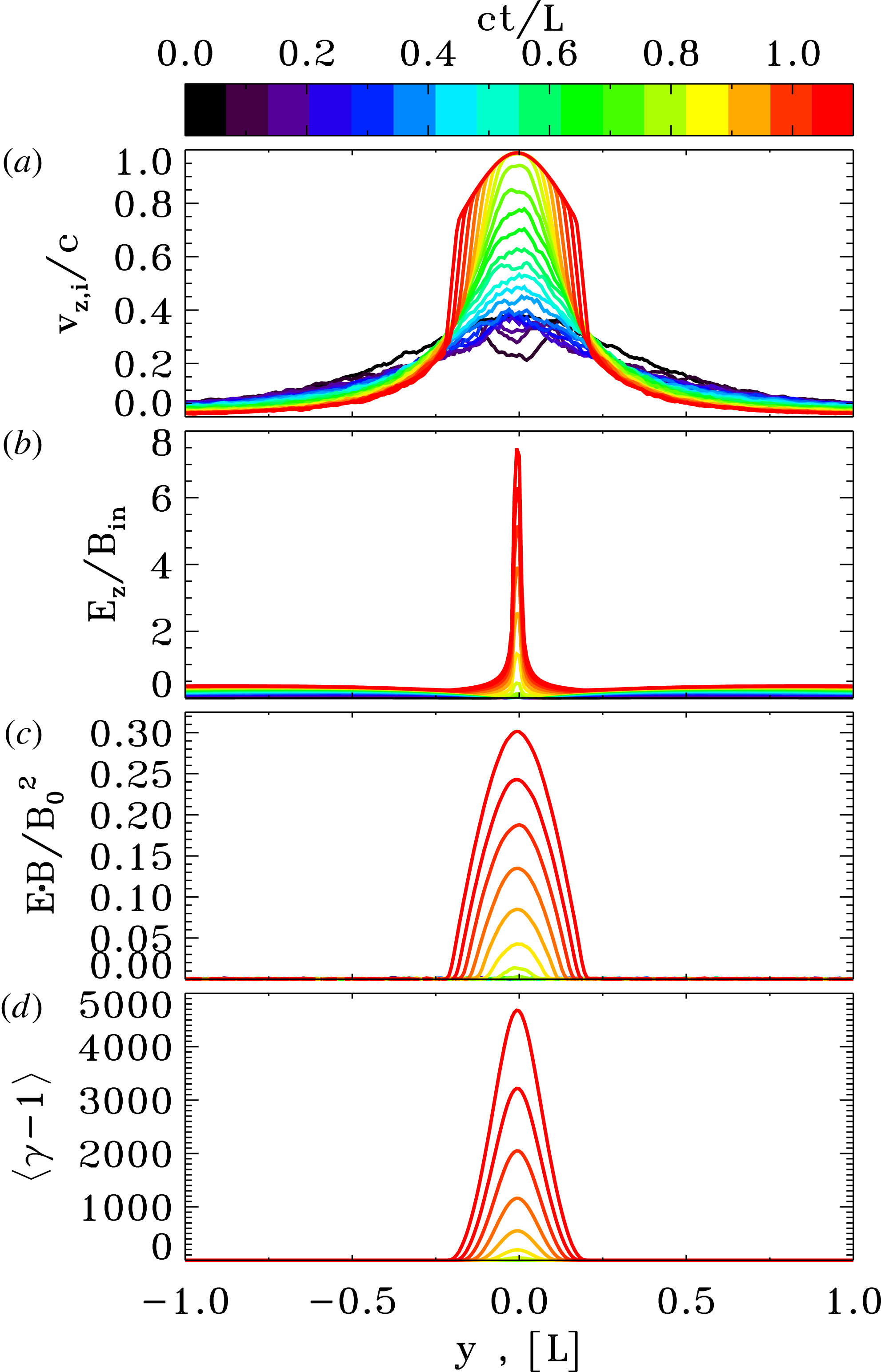
Spatial profiles of various quantities from a PIC simulation of an X-point collapse with guide field and magnetization
 $\unicode[STIX]{x1D70E}_{L}=4\times 10^{4}$
, which corresponds to the red curves in figure 7. As a function of the coordinate
$\unicode[STIX]{x1D70E}_{L}=4\times 10^{4}$
, which corresponds to the red curves in figure 7. As a function of the coordinate
 $y$
along the inflow direction, we plot at
$y$
along the inflow direction, we plot at
 $x=0$
: (a) the bulk speed of positrons, in units of the speed of light (the bulk speed of electrons is equal and opposite); (b) the ratio of the out-of-plane electric field
$x=0$
: (a) the bulk speed of positrons, in units of the speed of light (the bulk speed of electrons is equal and opposite); (b) the ratio of the out-of-plane electric field
 $E_{z}$
to the in-plane magnetic field
$E_{z}$
to the in-plane magnetic field
 $B_{in}=\sqrt{B_{x}^{2}+B_{y}^{2}}$
; (c) the parameter
$B_{in}=\sqrt{B_{x}^{2}+B_{y}^{2}}$
; (c) the parameter
 $\boldsymbol{E}\boldsymbol{\cdot }\boldsymbol{B}/B_{0}^{2}$
, which explicitly shows when the force-free condition
$\boldsymbol{E}\boldsymbol{\cdot }\boldsymbol{B}/B_{0}^{2}$
, which explicitly shows when the force-free condition
 $\boldsymbol{E}\boldsymbol{\cdot }\boldsymbol{B}=0$
is falsified; (d) the mean particle Lorentz factor.
$\boldsymbol{E}\boldsymbol{\cdot }\boldsymbol{B}=0$
is falsified; (d) the mean particle Lorentz factor.
The fact that PIC results at early times are independent of
 $\unicode[STIX]{x1D70E}_{L}$
is further illustrated in figure 7, where we present the temporal evolution of various quantities for three values of the magnetization:
$\unicode[STIX]{x1D70E}_{L}$
is further illustrated in figure 7, where we present the temporal evolution of various quantities for three values of the magnetization:
 $\unicode[STIX]{x1D70E}_{L}=4\times 10^{2}$
(blue),
$\unicode[STIX]{x1D70E}_{L}=4\times 10^{2}$
(blue),
 $\unicode[STIX]{x1D70E}_{L}=4\times 10^{3}$
(green) and
$\unicode[STIX]{x1D70E}_{L}=4\times 10^{3}$
(green) and
 $\unicode[STIX]{x1D70E}_{L}=4\times 10^{4}$
(red). Both the value of
$\unicode[STIX]{x1D70E}_{L}=4\times 10^{4}$
(red). Both the value of
 $a(t)=\unicode[STIX]{x1D706}^{1/2}(B_{x}/B_{y})^{1/4}$
and of the electric field
$a(t)=\unicode[STIX]{x1D706}^{1/2}(B_{x}/B_{y})^{1/4}$
and of the electric field
 $E(t)$
(in units of
$E(t)$
(in units of
 $B_{0}$
) at the location
$B_{0}$
) at the location
 $(-0.1L,0.1L)$
are independent of
$(-0.1L,0.1L)$
are independent of
 $\unicode[STIX]{x1D70E}_{L}$
, as long as
$\unicode[STIX]{x1D70E}_{L}$
, as long as
 $ct/L\lesssim 1$
, and they are in excellent agreement with the results of force-free simulations presented in figure 4. In other words, the physics at early times is entirely regulated by large-scale electromagnetic stresses, with no appreciable particle kinetic effects. Carried along by the converging magnetic fields of the collapsing X-point, particles are flowing into the central region, with a reconnection speed of
$ct/L\lesssim 1$
, and they are in excellent agreement with the results of force-free simulations presented in figure 4. In other words, the physics at early times is entirely regulated by large-scale electromagnetic stresses, with no appreciable particle kinetic effects. Carried along by the converging magnetic fields of the collapsing X-point, particles are flowing into the central region, with a reconnection speed of
 ${\sim}0.2c$
(averaged over a square of side equal to
${\sim}0.2c$
(averaged over a square of side equal to
 $L$
around the centre). This is significantly higher compared to the typical reconnection rate for a plane current sheet configuration. For a relativistic current sheet with guide field of the same strength as the alternating field, the reconnection rate is only
$L$
around the centre). This is significantly higher compared to the typical reconnection rate for a plane current sheet configuration. For a relativistic current sheet with guide field of the same strength as the alternating field, the reconnection rate is only
 $v_{\text{rec}}/c\sim 0.02$
(Sironi & Spitkovsky 2017, in preparation)Footnote
6
.
$v_{\text{rec}}/c\sim 0.02$
(Sironi & Spitkovsky 2017, in preparation)Footnote
6
.
We have argued in § 2 that as the system evolves and the
 $a(t)$
parameter increases, the electric current may become charge starved. In figure 7, this is clearly indicated by the time when the force-free condition
$a(t)$
parameter increases, the electric current may become charge starved. In figure 7, this is clearly indicated by the time when the force-free condition
 $\boldsymbol{E}\boldsymbol{\cdot }\boldsymbol{B}=0$
is violated, as shown in panel (d). Higher values of
$\boldsymbol{E}\boldsymbol{\cdot }\boldsymbol{B}=0$
is violated, as shown in panel (d). Higher values of
 $\unicode[STIX]{x1D70E}_{L}$
lead to an earlier onset of charge starvation: the simulation with
$\unicode[STIX]{x1D70E}_{L}$
lead to an earlier onset of charge starvation: the simulation with
 $\unicode[STIX]{x1D70E}_{L}=4\times 10^{4}$
becomes charge starved at
$\unicode[STIX]{x1D70E}_{L}=4\times 10^{4}$
becomes charge starved at
 $ct/L\simeq 0.75$
, the simulation with
$ct/L\simeq 0.75$
, the simulation with
 $\unicode[STIX]{x1D70E}_{L}=4\times 10^{3}$
at
$\unicode[STIX]{x1D70E}_{L}=4\times 10^{3}$
at
 $ct/L\simeq 1.1$
and the simulation with
$ct/L\simeq 1.1$
and the simulation with
 $\unicode[STIX]{x1D70E}_{L}=4\times 10^{2}$
at
$\unicode[STIX]{x1D70E}_{L}=4\times 10^{2}$
at
 $ct/L\simeq 1.5$
. This is expected as higher
$ct/L\simeq 1.5$
. This is expected as higher
 $\unicode[STIX]{x1D70E}$
corresponds to fewer available charges. The onset of charge starvation is accompanied by a deviation of the curves in panels (a,b) from the results of force-free simulations, where the condition
$\unicode[STIX]{x1D70E}$
corresponds to fewer available charges. The onset of charge starvation is accompanied by a deviation of the curves in panels (a,b) from the results of force-free simulations, where the condition
 $\boldsymbol{E}\boldsymbol{\cdot }\boldsymbol{B}=0$
is imposed by hand at all times.
$\boldsymbol{E}\boldsymbol{\cdot }\boldsymbol{B}=0$
is imposed by hand at all times.
The physics of charge starvation is illustrated in figure 8, for the case
 $\unicode[STIX]{x1D70E}_{L}=4\times 10^{4}$
that corresponds to the red curves in figure 7. In response to the rapidly increasing curl of the magnetic field, the
$\unicode[STIX]{x1D70E}_{L}=4\times 10^{4}$
that corresponds to the red curves in figure 7. In response to the rapidly increasing curl of the magnetic field, the
 $z$
velocity of the charge carriers has to increase (figure 8
a, for positrons), while their density stays nearly unchanged. When the drifting speed reaches the speed of light, at
$z$
velocity of the charge carriers has to increase (figure 8
a, for positrons), while their density stays nearly unchanged. When the drifting speed reaches the speed of light, at
 $ct/L\simeq 0.8$
in figure 8(a), the particle electric current cannot sustain the curl of the magnetic field any longer and the displacement current takes over. As a result, the electric field grows to violate the force-free condition
$ct/L\simeq 0.8$
in figure 8(a), the particle electric current cannot sustain the curl of the magnetic field any longer and the displacement current takes over. As a result, the electric field grows to violate the force-free condition
 $\boldsymbol{E}\boldsymbol{\cdot }\boldsymbol{B}=0$
. In fact, panel (c) shows that the value of
$\boldsymbol{E}\boldsymbol{\cdot }\boldsymbol{B}=0$
. In fact, panel (c) shows that the value of
 $\boldsymbol{E}\boldsymbol{\cdot }\boldsymbol{B}$
departs from zero at
$\boldsymbol{E}\boldsymbol{\cdot }\boldsymbol{B}$
departs from zero at
 $ct/L\simeq 0.8$
, i.e. right when the particle drift velocity approaches the speed of light. The non-zero
$ct/L\simeq 0.8$
, i.e. right when the particle drift velocity approaches the speed of light. The non-zero
 $\boldsymbol{E}\boldsymbol{\cdot }\boldsymbol{B}$
triggers the onset of efficient particle acceleration, as shown by the profile of the mean particle Lorentz factor in panel (d). Indeed, the locations of efficient particle acceleration (i.e. where
$\boldsymbol{E}\boldsymbol{\cdot }\boldsymbol{B}$
triggers the onset of efficient particle acceleration, as shown by the profile of the mean particle Lorentz factor in panel (d). Indeed, the locations of efficient particle acceleration (i.e. where
 $\langle \unicode[STIX]{x1D6FE}\rangle \gg 1$
) are spatially coincident with the regions where
$\langle \unicode[STIX]{x1D6FE}\rangle \gg 1$
) are spatially coincident with the regions where
 $\boldsymbol{E}\boldsymbol{\cdot }\boldsymbol{B}\neq 0$
. There, the pressure of accelerated particles provides a significant back reaction onto the field collapse, and the agreement with the force-free results necessarily fails.
$\boldsymbol{E}\boldsymbol{\cdot }\boldsymbol{B}\neq 0$
. There, the pressure of accelerated particles provides a significant back reaction onto the field collapse, and the agreement with the force-free results necessarily fails.
After the onset of charge starvation, the maximum particle energy dramatically increases (see figure 7 e). It is this period of rapid acceleration that will be extensively studied in the following sections. Here, and hereafter, the maximum particle Lorentz factor plotted in figure 7(e) is defined as
 $$\begin{eqnarray}\unicode[STIX]{x1D6FE}_{\max }=\frac{\displaystyle \int \unicode[STIX]{x1D6FE}^{n_{\text{cut}}}\,\text{d}N/\text{d}\unicode[STIX]{x1D6FE}\,\text{d}\unicode[STIX]{x1D6FE}}{\displaystyle \int \unicode[STIX]{x1D6FE}^{n_{\text{cut}-1}}\,\text{d}N/\text{d}\unicode[STIX]{x1D6FE}\,\text{d}\unicode[STIX]{x1D6FE}},\end{eqnarray}$$
where
 $n_{\text{cut}}$
is empirically chosen to be
$n_{\text{cut}}$
is empirically chosen to be
 $n_{\text{cut}}=6$
(see also Bai et al.
Reference Bai, Caprioli, Sironi and Spitkovsky2015). If the particle energy spectrum takes the form
$n_{\text{cut}}=6$
(see also Bai et al.
Reference Bai, Caprioli, Sironi and Spitkovsky2015). If the particle energy spectrum takes the form
 $\text{d}N/\text{d}\unicode[STIX]{x1D6FE}\propto \unicode[STIX]{x1D6FE}^{-s}\exp (-\unicode[STIX]{x1D6FE}/\unicode[STIX]{x1D6FE}_{\text{cut}})$
with power-law slope
$\text{d}N/\text{d}\unicode[STIX]{x1D6FE}\propto \unicode[STIX]{x1D6FE}^{-s}\exp (-\unicode[STIX]{x1D6FE}/\unicode[STIX]{x1D6FE}_{\text{cut}})$
with power-law slope
 $s$
and exponential cutoff at
$s$
and exponential cutoff at
 $\unicode[STIX]{x1D6FE}_{\text{cut}}$
, then our definition yields
$\unicode[STIX]{x1D6FE}_{\text{cut}}$
, then our definition yields
 $\unicode[STIX]{x1D6FE}_{\max }\sim (n_{\text{cut}}-s)\unicode[STIX]{x1D6FE}_{\text{cut}}$
.
$\unicode[STIX]{x1D6FE}_{\max }\sim (n_{\text{cut}}-s)\unicode[STIX]{x1D6FE}_{\text{cut}}$
.
Late time evolution of the X-point collapse in PIC simulations with guide field, for two different magnetizations:
 $\unicode[STIX]{x1D70E}_{L}=4\times 10^{3}$
(left) and
$\unicode[STIX]{x1D70E}_{L}=4\times 10^{3}$
(left) and
 $\unicode[STIX]{x1D70E}_{L}=4\times 10^{4}$
(right). The plots show the out-of-plane field at
$\unicode[STIX]{x1D70E}_{L}=4\times 10^{4}$
(right). The plots show the out-of-plane field at
 $ct/L=1.5$
, 3, 4.5, 6, from (a–d). This figure corresponds to figure 5(a), which shows the results of force-free simulations.
$ct/L=1.5$
, 3, 4.5, 6, from (a–d). This figure corresponds to figure 5(a), which shows the results of force-free simulations.
Late time evolution of the X-point collapse in PIC simulations with guide field, for two different magnetizations:
 $\unicode[STIX]{x1D70E}_{L}=4\times 10^{3}$
(left) and
$\unicode[STIX]{x1D70E}_{L}=4\times 10^{3}$
(left) and
 $\unicode[STIX]{x1D70E}_{L}=4\times 10^{4}$
(right). The plots show the quantity
$\unicode[STIX]{x1D70E}_{L}=4\times 10^{4}$
(right). The plots show the quantity
 $1-E^{2}/B^{2}$
at
$1-E^{2}/B^{2}$
at
 $ct/L=1.5$
, 3, 4.5, 6, from (a–d) (strictly speaking, we plot
$ct/L=1.5$
, 3, 4.5, 6, from (a–d) (strictly speaking, we plot
 $\max [0,1-E^{2}/B^{2}]$
, for direct comparison with force-free simulations, that implicitly constrain
$\max [0,1-E^{2}/B^{2}]$
, for direct comparison with force-free simulations, that implicitly constrain
 $E\leqslant B$
). This figure corresponds to figure 5(b), which shows the results of force-free simulations.
$E\leqslant B$
). This figure corresponds to figure 5(b), which shows the results of force-free simulations.

As the collapse proceeds beyond
 $ct/L\sim 1$
, the system approaches a self-similar evolution, as we have already emphasized for our force-free simulations (see figure 5). As shown in figure 9, the X-point evolves into a thin current sheet with two Y-points at its ends, which move with speed very close to the speed of light. The current sheet is supported by the pressure of the compressed guide field (as it is apparent in figure 9) and by the kinetic pressure of the accelerated particles. As illustrated in figure 9, the current sheet is thinner for lower magnetizations, at fixed
$ct/L\sim 1$
, the system approaches a self-similar evolution, as we have already emphasized for our force-free simulations (see figure 5). As shown in figure 9, the X-point evolves into a thin current sheet with two Y-points at its ends, which move with speed very close to the speed of light. The current sheet is supported by the pressure of the compressed guide field (as it is apparent in figure 9) and by the kinetic pressure of the accelerated particles. As illustrated in figure 9, the current sheet is thinner for lower magnetizations, at fixed
 $L/c/\unicode[STIX]{x1D714}_{p}$
(compare
$L/c/\unicode[STIX]{x1D714}_{p}$
(compare
 $\unicode[STIX]{x1D70E}_{L}=4\times 10^{3}$
on the left and
$\unicode[STIX]{x1D70E}_{L}=4\times 10^{3}$
on the left and
 $\unicode[STIX]{x1D70E}_{L}=4\times 10^{4}$
on the right). Roughly, the thickness of the current sheet at this stage is set by the Larmor radius
$\unicode[STIX]{x1D70E}_{L}=4\times 10^{4}$
on the right). Roughly, the thickness of the current sheet at this stage is set by the Larmor radius
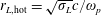 $r_{L,\text{hot}}=\sqrt{\unicode[STIX]{x1D70E}_{L}}c/\unicode[STIX]{x1D714}_{p}$
of the high-energy particles heated/accelerated by reconnection, which explains the variation of the current sheet thickness with
$r_{L,\text{hot}}=\sqrt{\unicode[STIX]{x1D70E}_{L}}c/\unicode[STIX]{x1D714}_{p}$
of the high-energy particles heated/accelerated by reconnection, which explains the variation of the current sheet thickness with
 $\unicode[STIX]{x1D70E}_{L}$
in figure 9. A long thin current sheet is expected to fragment into a chain of plasmoids/magnetic islands (e.g. Uzdensky, Loureiro & Schekochihin Reference Uzdensky, Loureiro and Schekochihin2010), when the length-to-thickness ratio is much larger than unity. At fixed time and hence similar sheet length, it is then more likely that the fragmentation into plasmoids appears at lower magnetizations, since a lower
$\unicode[STIX]{x1D70E}_{L}$
in figure 9. A long thin current sheet is expected to fragment into a chain of plasmoids/magnetic islands (e.g. Uzdensky, Loureiro & Schekochihin Reference Uzdensky, Loureiro and Schekochihin2010), when the length-to-thickness ratio is much larger than unity. At fixed time and hence similar sheet length, it is then more likely that the fragmentation into plasmoids appears at lower magnetizations, since a lower
 $\unicode[STIX]{x1D70E}_{L}$
results in a thinner current sheet. This is in agreement with figure 9, and we have further checked that the current sheet in the simulation with
$\unicode[STIX]{x1D70E}_{L}$
results in a thinner current sheet. This is in agreement with figure 9, and we have further checked that the current sheet in the simulation with
 $\unicode[STIX]{x1D70E}_{L}=4\times 10^{2}$
starts fragmenting at even earlier times.
$\unicode[STIX]{x1D70E}_{L}=4\times 10^{2}$
starts fragmenting at even earlier times.
In the small-scale X-points in between the self-generated plasmoids, the electric field can approach and exceed the magnetic field. This is apparent in figure 10 – referring to the same simulations as in figure 9 – where we show the value of
 $1-E^{2}/B^{2}$
, which quantifies the strength of the electric field relative to the magnetic field. In the case of
$1-E^{2}/B^{2}$
, which quantifies the strength of the electric field relative to the magnetic field. In the case of
 $\unicode[STIX]{x1D70E}_{L}=4\times 10^{3}$
(left side), the microscopic regions in between the plasmoids are characterized by
$\unicode[STIX]{x1D70E}_{L}=4\times 10^{3}$
(left side), the microscopic regions in between the plasmoids are characterized by
 $E>B$
(see, e.g. at the centre of panel (d)). In addition, ahead of each of the two Y-points, a bow-shaped area exists where
$E>B$
(see, e.g. at the centre of panel (d)). In addition, ahead of each of the two Y-points, a bow-shaped area exists where
 $E\sim B$
(e.g. at
$E\sim B$
(e.g. at
 $|x|\sim 5L$
and
$|x|\sim 5L$
and
 $y\sim 0$
in panel (c)). The two Y-points move at the Alfvén speed, which is comparable to the speed of light for our
$y\sim 0$
in panel (c)). The two Y-points move at the Alfvén speed, which is comparable to the speed of light for our
 $\unicode[STIX]{x1D70E}_{L}\gg 1$
plasma. So, the fact that
$\unicode[STIX]{x1D70E}_{L}\gg 1$
plasma. So, the fact that
 $E\sim B$
ahead of the Y-points is just a manifestation of the relativistic nature of the reconnection outflows. For
$E\sim B$
ahead of the Y-points is just a manifestation of the relativistic nature of the reconnection outflows. For
 $\unicode[STIX]{x1D70E}_{L}=4\times 10^{3}$
(left side in figure 10), the electric energy in the bulk of the inflow region is much smaller than the magnetic energy, corresponding to
$\unicode[STIX]{x1D70E}_{L}=4\times 10^{3}$
(left side in figure 10), the electric energy in the bulk of the inflow region is much smaller than the magnetic energy, corresponding to
 $1-E^{2}/B^{2}\sim 0.6$
. Or equivalently, the reconnection speed is significantly smaller than the speed of light. The highly relativistic case of
$1-E^{2}/B^{2}\sim 0.6$
. Or equivalently, the reconnection speed is significantly smaller than the speed of light. The highly relativistic case of
 $\unicode[STIX]{x1D70E}_{L}=4\times 10^{4}$
(right panel in figure 10) shows a different picture. Here, a large volume with
$\unicode[STIX]{x1D70E}_{L}=4\times 10^{4}$
(right panel in figure 10) shows a different picture. Here, a large volume with
 $E\sim B$
develops in the inflow region. In other words, the reconnection speed approaches the speed of light in a macroscopic region. In the next subsection, we will show that an inflow speed near the speed of light (or equivalently,
$E\sim B$
develops in the inflow region. In other words, the reconnection speed approaches the speed of light in a macroscopic region. In the next subsection, we will show that an inflow speed near the speed of light (or equivalently,
 $E\sim B$
) is a generic by-product of high-
$E\sim B$
) is a generic by-product of high-
 $\unicode[STIX]{x1D70E}_{L}$
reconnectionFootnote
7
.
$\unicode[STIX]{x1D70E}_{L}$
reconnectionFootnote
7
.
Initial phase of a solitary X-point collapse in PIC simulations with zero guide field, for two different magnetizations:
 $\unicode[STIX]{x1D70E}_{L}=4\times 10^{3}$
(left) and
$\unicode[STIX]{x1D70E}_{L}=4\times 10^{3}$
(left) and
 $\unicode[STIX]{x1D70E}_{L}=4\times 10^{4}$
(right). The plots show the quantity
$\unicode[STIX]{x1D70E}_{L}=4\times 10^{4}$
(right). The plots show the quantity
 $1-E^{2}/B^{2}$
(strictly speaking, we plot
$1-E^{2}/B^{2}$
(strictly speaking, we plot
 $\max [0,1-E^{2}/B^{2}]$
) at
$\max [0,1-E^{2}/B^{2}]$
) at
 $ct/L=0.25$
, 0.5, 0.75 and 1, from panels (a–d).
$ct/L=0.25$
, 0.5, 0.75 and 1, from panels (a–d).

Late time evolution of the X-point collapse in PIC simulations with zero guide field, for two different magnetizations:
 $\unicode[STIX]{x1D70E}_{L}=4\times 10^{3}$
(left) and
$\unicode[STIX]{x1D70E}_{L}=4\times 10^{3}$
(left) and
 $\unicode[STIX]{x1D70E}_{L}=4\times 10^{4}$
(right). The plots show the quantity
$\unicode[STIX]{x1D70E}_{L}=4\times 10^{4}$
(right). The plots show the quantity
 $1-E^{2}/B^{2}$
(strictly speaking, we plot
$1-E^{2}/B^{2}$
(strictly speaking, we plot
 $\max [0,1-E^{2}/B^{2}]$
) at
$\max [0,1-E^{2}/B^{2}]$
) at
 $ct/L=1.5$
, 3, 4.5, 6, from panels (a–d).
$ct/L=1.5$
, 3, 4.5, 6, from panels (a–d).

4.3 Stressed X-point collapse without guide field
Figure 11 shows the initial phase (
 $ct/L\leqslant 1$
) of the collapse of an X-point in PIC simulations with
$ct/L\leqslant 1$
) of the collapse of an X-point in PIC simulations with
 $\unicode[STIX]{x1D706}=1/\sqrt{2}$
and with zero guide field, for two different magnetizations:
$\unicode[STIX]{x1D706}=1/\sqrt{2}$
and with zero guide field, for two different magnetizations:
 $\unicode[STIX]{x1D70E}_{L}=4\times 10^{3}$
(left) and
$\unicode[STIX]{x1D70E}_{L}=4\times 10^{3}$
(left) and
 $\unicode[STIX]{x1D70E}_{L}=4\times 10^{4}$
(right). We plot the quantity
$\unicode[STIX]{x1D70E}_{L}=4\times 10^{4}$
(right). We plot the quantity
 $1-E^{2}/B^{2}$
(more precisely, we present
$1-E^{2}/B^{2}$
(more precisely, we present
 $\max [0,1-E^{2}/B^{2}]$
), in order to identify the regions where the electric field is comparable to the magnetic field (green or blue areas in the plot). For both
$\max [0,1-E^{2}/B^{2}]$
), in order to identify the regions where the electric field is comparable to the magnetic field (green or blue areas in the plot). For both
 $\unicode[STIX]{x1D70E}_{L}=4\times 10^{3}$
(left) and
$\unicode[STIX]{x1D70E}_{L}=4\times 10^{3}$
(left) and
 $\unicode[STIX]{x1D70E}_{L}=4\times 10^{4}$
(right), the current sheet is subject to copious fragmentation into plasmoids since early times, in contrast with the guide field case (compare with figure 6). There, the current sheet was supported by the pressure of the compressed guide field, and therefore its thickness was larger, making it less prone to fragmentation (at a fixed time
$\unicode[STIX]{x1D70E}_{L}=4\times 10^{4}$
(right), the current sheet is subject to copious fragmentation into plasmoids since early times, in contrast with the guide field case (compare with figure 6). There, the current sheet was supported by the pressure of the compressed guide field, and therefore its thickness was larger, making it less prone to fragmentation (at a fixed time
 $ct/L$
). In addition, a comparison of figure 11, which refers to early times (up to
$ct/L$
). In addition, a comparison of figure 11, which refers to early times (up to
 $ct/L=1$
), with figure 12, that follows the system up to
$ct/L=1$
), with figure 12, that follows the system up to
 $ct/L=6$
, shows the remarkable self-similarity of the evolution, for both magnetizations. First, the macroscopic distribution of
$ct/L=6$
, shows the remarkable self-similarity of the evolution, for both magnetizations. First, the macroscopic distribution of
 $E^{2}/B^{2}$
(and hence that of the drift velocity) at later times is a scaled copy of that at previous times, with the overall length scale increasing linearly with time (at the speed of light). This implies that the reconnection rate over the whole configurations remains fixed in time, as we indeed confirm below. Second, the size of the largest plasmoids generated in the current sheet is also a fixed fraction of the overall scale,
$E^{2}/B^{2}$
(and hence that of the drift velocity) at later times is a scaled copy of that at previous times, with the overall length scale increasing linearly with time (at the speed of light). This implies that the reconnection rate over the whole configurations remains fixed in time, as we indeed confirm below. Second, the size of the largest plasmoids generated in the current sheet is also a fixed fraction of the overall scale,
 ${\sim}0.1$
of the current sheet length.
${\sim}0.1$
of the current sheet length.
In figures 11 and 12, the plasmoids generated by the secondary tearing instability (Uzdensky et al. Reference Uzdensky, Loureiro and Schekochihin2010) appear as yellow structures, i.e. with magnetic energy much larger than the electric energy. In contrast, the region in between each pair of plasmoids harbours a microscopic X-point, where the electric field can exceed the magnetic field. The size of these microscopic X-points is controlled by plasma kinetics, in contrast to the original macroscopic X-point. They play a major role for particle injection into the acceleration process, as we argue in the next subsection.
As observed in the case of guide field collapse, the two bow-shaped regions ahead of the Y-points (to the left and to the right of the reconnection layer) are moving relativistically, yielding
 $E\sim B$
(green and blue colours in the figures). In addition, in the high magnetization case
$E\sim B$
(green and blue colours in the figures). In addition, in the high magnetization case
 $\unicode[STIX]{x1D70E}_{L}=4\times 10^{4}$
(right side of figures 11 and 12), a macroscopic region appears in the bulk inflow where the electric field is comparable to the magnetic field. Here, the inflow rate approaches the speed of light, as we have already described in the case of guide field reconnection (right side of figure 10).
$\unicode[STIX]{x1D70E}_{L}=4\times 10^{4}$
(right side of figures 11 and 12), a macroscopic region appears in the bulk inflow where the electric field is comparable to the magnetic field. Here, the inflow rate approaches the speed of light, as we have already described in the case of guide field reconnection (right side of figure 10).
This is further illustrated in figure 13, where we present the temporal evolution of various quantities, from a suite of PIC simulations of X-point collapse with vanishing guide field, having three different magnetizations:
 $\unicode[STIX]{x1D70E}_{L}=4\times 10^{2}$
(blue),
$\unicode[STIX]{x1D70E}_{L}=4\times 10^{2}$
(blue),
 $\unicode[STIX]{x1D70E}_{L}=4\times 10^{3}$
(green) and
$\unicode[STIX]{x1D70E}_{L}=4\times 10^{3}$
(green) and
 $\unicode[STIX]{x1D70E}_{L}=4\times 10^{4}$
(red). The reconnection rate
$\unicode[STIX]{x1D70E}_{L}=4\times 10^{4}$
(red). The reconnection rate
 $v_{\text{rec}}/c$
(panel b), which is measured as the inflow speed averaged over a macroscopic square of side equal to
$v_{\text{rec}}/c$
(panel b), which is measured as the inflow speed averaged over a macroscopic square of side equal to
 $L$
centred at
$L$
centred at
 $x=y=0$
, shows in the asymptotic state (i.e. at
$x=y=0$
, shows in the asymptotic state (i.e. at
 $ct/L\gtrsim 0.5$
) a clear dependence on
$ct/L\gtrsim 0.5$
) a clear dependence on
 $\unicode[STIX]{x1D70E}_{L}$
, reaching
$\unicode[STIX]{x1D70E}_{L}$
, reaching
 $v_{\text{ rec}}/c\sim 0.8$
for our high magnetization case
$v_{\text{ rec}}/c\sim 0.8$
for our high magnetization case
 $\unicode[STIX]{x1D70E}_{L}=4\times 10^{4}$
(red). This trend has already been described by Liu et al. (Reference Liu, Guo, Daughton, Li and Hesse2015). The critical difference, though, is that their measurement was performed on microscopic skin depth scales, whereas our results show that reconnection velocities near the speed of light can be achieved over macroscopic scales
$\unicode[STIX]{x1D70E}_{L}=4\times 10^{4}$
(red). This trend has already been described by Liu et al. (Reference Liu, Guo, Daughton, Li and Hesse2015). The critical difference, though, is that their measurement was performed on microscopic skin depth scales, whereas our results show that reconnection velocities near the speed of light can be achieved over macroscopic scales
 $L\gg c/\unicode[STIX]{x1D714}_{p}$
. In addition, such inflow speed is significantly larger than what is measured on macroscopic scales in the case of plane-parallel steady-state reconnection, where the reconnection rate typically approaches
$L\gg c/\unicode[STIX]{x1D714}_{p}$
. In addition, such inflow speed is significantly larger than what is measured on macroscopic scales in the case of plane-parallel steady-state reconnection, where the reconnection rate typically approaches
 $v_{\text{ rec}}/c\sim 0.2$
in the high magnetization limit (Sironi & Spitkovsky Reference Sironi and Spitkovsky2014; Guo et al.
Reference Guo, Liu, Daughton and Li2015).
$v_{\text{ rec}}/c\sim 0.2$
in the high magnetization limit (Sironi & Spitkovsky Reference Sironi and Spitkovsky2014; Guo et al.
Reference Guo, Liu, Daughton and Li2015).
The dependence of the reconnection speed on
 $\unicode[STIX]{x1D70E}_{L}$
is also revealed in figure 13(a), where we present the temporal evolution of the electric field
$\unicode[STIX]{x1D70E}_{L}$
is also revealed in figure 13(a), where we present the temporal evolution of the electric field
 $E(t)$
measured at
$E(t)$
measured at
 $(x,y)=(-0.1L,0.1L)$
, in units of the initial magnetic field at
$(x,y)=(-0.1L,0.1L)$
, in units of the initial magnetic field at
 $x=L$
. The variation in slope in figure 13(a) is indeed driven by the different reconnection speeds, since
$x=L$
. The variation in slope in figure 13(a) is indeed driven by the different reconnection speeds, since
 $E\sim v_{\text{rec}}B/c$
in the inflow region.
$E\sim v_{\text{rec}}B/c$
in the inflow region.
Temporal evolution of various quantities from PIC simulations of solitary X-point collapse with zero guide field, for three values of the magnetization:
 $\unicode[STIX]{x1D70E}_{L}=4\times 10^{2}$
(blue),
$\unicode[STIX]{x1D70E}_{L}=4\times 10^{2}$
(blue),
 $\unicode[STIX]{x1D70E}_{L}=4\times 10^{3}$
(green) and
$\unicode[STIX]{x1D70E}_{L}=4\times 10^{3}$
(green) and
 $\unicode[STIX]{x1D70E}_{L}=4\times 10^{4}$
(red). The corresponding plot for the case of non-zero guide field is in figure 7. As a function of time, we plot: (a) the value of the electric field strength
$\unicode[STIX]{x1D70E}_{L}=4\times 10^{4}$
(red). The corresponding plot for the case of non-zero guide field is in figure 7. As a function of time, we plot: (a) the value of the electric field strength
 $E(t)$
at the location
$E(t)$
at the location
 $(-0.1L,0.1L)$
in units of the initial magnetic field at
$(-0.1L,0.1L)$
in units of the initial magnetic field at
 $x=L$
; (b), the reconnection rate, defined as the inflow speed along the
$x=L$
; (b), the reconnection rate, defined as the inflow speed along the
 $y$
direction averaged over a square of side equal to
$y$
direction averaged over a square of side equal to
 $L$
around the central region; (c) the maximum particle Lorentz factor
$L$
around the central region; (c) the maximum particle Lorentz factor
 $\unicode[STIX]{x1D6FE}_{\max }$
(as defined in (4.1)), in units of the thermal value
$\unicode[STIX]{x1D6FE}_{\max }$
(as defined in (4.1)), in units of the thermal value
 $\unicode[STIX]{x1D6FE}_{\text{th}}\simeq 1+(\hat{\unicode[STIX]{x1D6FE}}-1)^{-1}kT/mc^{2}$
, which in this case of a cold plasma reduces to
$\unicode[STIX]{x1D6FE}_{\text{th}}\simeq 1+(\hat{\unicode[STIX]{x1D6FE}}-1)^{-1}kT/mc^{2}$
, which in this case of a cold plasma reduces to
 $\unicode[STIX]{x1D6FE}_{\text{th}}\simeq 1$
; the inset in panel (c) shows the same quantity on a double logarithmic scale, demonstrating that
$\unicode[STIX]{x1D6FE}_{\text{th}}\simeq 1$
; the inset in panel (c) shows the same quantity on a double logarithmic scale, demonstrating that
 $\unicode[STIX]{x1D6FE}_{\max }\propto t^{2}$
(black dashed line).
$\unicode[STIX]{x1D6FE}_{\max }\propto t^{2}$
(black dashed line).

Interestingly, the electric field increases linearly with time. This is ultimately a manifestation of the self-similar macroscopic evolution of the system. Indeed, since in the initial configuration the magnetic field strength grows linearly with distance from the origin (i.e. the centre of the X-point) and the current sheet size grows linearly with time, the mean magnetic and electric fields in the volume surrounding the current sheet must also grow linearly, with their scaled distributions unchanged. The temporal evolution of the electric field has a direct impact on the maximum particle energy, which is shown in figure 13(c). Quite generally, its time evolution will be
 $$\begin{eqnarray}\unicode[STIX]{x1D6FE}_{\max }\propto Et\propto v_{\text{ rec}}Bt.\end{eqnarray}$$
Since both
 $E$
and
$E$
and
 $B$
in the reconnection region are scaling linearly with time (see figure 13
a), one expects
$B$
in the reconnection region are scaling linearly with time (see figure 13
a), one expects
 $\unicode[STIX]{x1D6FE}_{\max }\propto t^{2}$
, as indeed confirmed by the inset of panel (c) (compare with the dashed black line). This scaling is faster than in plane-parallel steady-state reconnection, where
$\unicode[STIX]{x1D6FE}_{\max }\propto t^{2}$
, as indeed confirmed by the inset of panel (c) (compare with the dashed black line). This scaling is faster than in plane-parallel steady-state reconnection, where
 $E(t)$
is constant in time, leading to
$E(t)$
is constant in time, leading to
 $\unicode[STIX]{x1D6FE}_{\max }\propto t$
. From the scaling in (4.2), one can understand the different normalizations of the curves in figure 13(c). Since
$\unicode[STIX]{x1D6FE}_{\max }\propto t$
. From the scaling in (4.2), one can understand the different normalizations of the curves in figure 13(c). Since
 $B\propto \sqrt{\unicode[STIX]{x1D70E}_{L}}$
we find that at fixed time
$B\propto \sqrt{\unicode[STIX]{x1D70E}_{L}}$
we find that at fixed time
 $$\begin{eqnarray}\unicode[STIX]{x1D6FE}_{\max }\propto v_{\text{ rec}}\sqrt{\unicode[STIX]{x1D70E}_{L}}\end{eqnarray}$$
and hence it grows with the magnetization. We find that for the model with
 $\unicode[STIX]{x1D70E}_{L}=4\times 10^{4}$
the reconnection rate is about twice that of the model with
$\unicode[STIX]{x1D70E}_{L}=4\times 10^{4}$
the reconnection rate is about twice that of the model with
 $\unicode[STIX]{x1D70E}_{L}=4\times 10^{2}$
(figure 13
b) and hence
$\unicode[STIX]{x1D70E}_{L}=4\times 10^{2}$
(figure 13
b) and hence
 $\unicode[STIX]{x1D6FE}_{\max }$
should be 20 times higher. This is in excellent agreement with the data in figure 13(c) (compare blue and red curves).
$\unicode[STIX]{x1D6FE}_{\max }$
should be 20 times higher. This is in excellent agreement with the data in figure 13(c) (compare blue and red curves).
4.4 Particle acceleration and emission signatures
In this section, we explore the physics of particle acceleration in a stressed X-point collapse with vanishing guide field, and we present the resulting particle distribution and synchrotron emission spectrum. In figure 14, we follow the trajectories of a number of particles in a simulation with
 $\unicode[STIX]{x1D70E}_{L}=4\times 10^{2}$
. The particles are selected such that their Lorentz factor exceeds a given threshold
$\unicode[STIX]{x1D70E}_{L}=4\times 10^{2}$
. The particles are selected such that their Lorentz factor exceeds a given threshold
 $\unicode[STIX]{x1D6FE}_{0}=30$
within the time interval
$\unicode[STIX]{x1D6FE}_{0}=30$
within the time interval
 $1.4\leqslant ct_{0}/L\leqslant 1.7$
, as indicated by the vertical dashed lines in the top panel. The temporal evolution of the Lorentz factor of such particles, presented in the top panel for the 30 positrons reaching the highest energies, follows the track
$1.4\leqslant ct_{0}/L\leqslant 1.7$
, as indicated by the vertical dashed lines in the top panel. The temporal evolution of the Lorentz factor of such particles, presented in the top panel for the 30 positrons reaching the highest energies, follows the track
 $\unicode[STIX]{x1D6FE}\propto t^{2}-t_{0}^{2}$
that is expected from
$\unicode[STIX]{x1D6FE}\propto t^{2}-t_{0}^{2}$
that is expected from
 $\text{d}\unicode[STIX]{x1D6FE}/\text{d}t\propto E(t)\propto t$
. Here,
$\text{d}\unicode[STIX]{x1D6FE}/\text{d}t\propto E(t)\propto t$
. Here,
 $t_{0}$
is the injection time, when the particle Lorentz factor
$t_{0}$
is the injection time, when the particle Lorentz factor
 $\unicode[STIX]{x1D6FE}$
first exceeds the threshold
$\unicode[STIX]{x1D6FE}$
first exceeds the threshold
 $\unicode[STIX]{x1D6FE}_{0}$
. The individual histories of single positrons might differ substantially, but overall figure 14(a) suggests that the acceleration process is dominated by direct acceleration by the reconnection electric field, as indeed it is expected for our configuration of a large-scale stressed X-point (see Sironi & Spitkovsky Reference Sironi and Spitkovsky2014; Guo et al.
Reference Guo, Liu, Daughton and Li2015; Nalewajko et al.
Reference Nalewajko, Uzdensky, Cerutti, Werner and Begelman2015, for a discussion of acceleration mechanisms in plane-parallel reconnection). We find that the particles presented in figure 14(a) are too energetic to be confined within the small-scale plasmoids in the current sheet, so any acceleration mechanism that relies on plasmoid mergers is found to be unimportant, in our set-up.
$\unicode[STIX]{x1D6FE}_{0}$
. The individual histories of single positrons might differ substantially, but overall figure 14(a) suggests that the acceleration process is dominated by direct acceleration by the reconnection electric field, as indeed it is expected for our configuration of a large-scale stressed X-point (see Sironi & Spitkovsky Reference Sironi and Spitkovsky2014; Guo et al.
Reference Guo, Liu, Daughton and Li2015; Nalewajko et al.
Reference Nalewajko, Uzdensky, Cerutti, Werner and Begelman2015, for a discussion of acceleration mechanisms in plane-parallel reconnection). We find that the particles presented in figure 14(a) are too energetic to be confined within the small-scale plasmoids in the current sheet, so any acceleration mechanism that relies on plasmoid mergers is found to be unimportant, in our set-up.
Physics of particle injection into the acceleration process, from a PIC simulation of stressed X-point collapse with vanishing guide field and
 $\unicode[STIX]{x1D70E}_{L}=4\times 10^{2}$
. (a) We select all the particles that exceed the threshold
$\unicode[STIX]{x1D70E}_{L}=4\times 10^{2}$
. (a) We select all the particles that exceed the threshold
 $\unicode[STIX]{x1D6FE}_{\text{0}}=30$
within a given time interval (chosen to be
$\unicode[STIX]{x1D6FE}_{\text{0}}=30$
within a given time interval (chosen to be
 $1.4\leqslant ct_{0}/L\leqslant 1.7$
, as indicated by the vertical dashed lines), and we plot the temporal evolution of the Lorentz factor of the 30 particles that at the final time reach the highest energies. The particle Lorentz factor increases as
$1.4\leqslant ct_{0}/L\leqslant 1.7$
, as indicated by the vertical dashed lines), and we plot the temporal evolution of the Lorentz factor of the 30 particles that at the final time reach the highest energies. The particle Lorentz factor increases as
 $\unicode[STIX]{x1D6FE}\propto t^{2}-t_{0}^{2}$
, where
$\unicode[STIX]{x1D6FE}\propto t^{2}-t_{0}^{2}$
, where
 $t_{0}$
marks the onset of acceleration (i.e. the time when
$t_{0}$
marks the onset of acceleration (i.e. the time when
 $\unicode[STIX]{x1D6FE}$
first exceeds
$\unicode[STIX]{x1D6FE}$
first exceeds
 $\unicode[STIX]{x1D6FE}_{0}$
). (b) For the same particles as in (a), we plot their locations at the onset of acceleration with open white circles, superimposed over the 2-D plot of
$\unicode[STIX]{x1D6FE}_{0}$
). (b) For the same particles as in (a), we plot their locations at the onset of acceleration with open white circles, superimposed over the 2-D plot of
 $1-E^{2}/B^{2}$
(more precisely, of
$1-E^{2}/B^{2}$
(more precisely, of
 $\max [0,1-E^{2}/B^{2}]$
) at
$\max [0,1-E^{2}/B^{2}]$
) at
 $ct/L=1.55$
. Comparison of (b) with (c) shows that particle injection is localized in the vicinity of the X-points in the current sheet (i.e. the blue regions where
$ct/L=1.55$
. Comparison of (b) with (c) shows that particle injection is localized in the vicinity of the X-points in the current sheet (i.e. the blue regions where
 $E>B$
).
$E>B$
).

Particle injection into the acceleration process happens in the charge-starved regions where
 $E>B$
, i.e. in the small-scale X-points that separate each pair of secondary plasmoids in the current sheet. Indeed, for the same particles as in figure 14(a,b) presents their locations at the onset of acceleration with open white circles, superimposed over the 2-D plot of
$E>B$
, i.e. in the small-scale X-points that separate each pair of secondary plasmoids in the current sheet. Indeed, for the same particles as in figure 14(a,b) presents their locations at the onset of acceleration with open white circles, superimposed over the 2-D plot of
 $1-E^{2}/B^{2}$
(more precisely, of
$1-E^{2}/B^{2}$
(more precisely, of
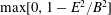 $\max [0,1-E^{2}/B^{2}]$
). Comparison of (b) with (c) shows that particle injection is localized in the vicinity of the small-scale X-points in the current sheet (i.e. the blue regions where
$\max [0,1-E^{2}/B^{2}]$
). Comparison of (b) with (c) shows that particle injection is localized in the vicinity of the small-scale X-points in the current sheet (i.e. the blue regions where
 $E>B$
). Despite occupying a relatively small fraction of the overall volume, such regions are of paramount importance for particle acceleration.
$E>B$
). Despite occupying a relatively small fraction of the overall volume, such regions are of paramount importance for particle acceleration.
Particle energy spectrum and synchrotron spectrum from a PIC simulation of stressed X-point collapse with vanishing guide field and
 $\unicode[STIX]{x1D70E}_{L}=4\times 10^{2}$
. Time is measured in units of
$\unicode[STIX]{x1D70E}_{L}=4\times 10^{2}$
. Time is measured in units of
 $L/c$
, see the colour bar at the top. (a) Evolution of the electron energy spectrum normalized to the total number of electrons. At late times, the spectrum approaches a hard distribution
$L/c$
, see the colour bar at the top. (a) Evolution of the electron energy spectrum normalized to the total number of electrons. At late times, the spectrum approaches a hard distribution
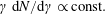 $\unicode[STIX]{x1D6FE}\,\text{d}N/\text{d}\unicode[STIX]{x1D6FE}\propto \text{const.}$
, much harder than the dotted line, which shows the case
$\unicode[STIX]{x1D6FE}\,\text{d}N/\text{d}\unicode[STIX]{x1D6FE}\propto \text{const.}$
, much harder than the dotted line, which shows the case
 $\unicode[STIX]{x1D6FE}\,\text{d}N/\text{d}\unicode[STIX]{x1D6FE}\propto \unicode[STIX]{x1D6FE}^{-1}$
corresponding to equal energy content in each decade of
$\unicode[STIX]{x1D6FE}\,\text{d}N/\text{d}\unicode[STIX]{x1D6FE}\propto \unicode[STIX]{x1D6FE}^{-1}$
corresponding to equal energy content in each decade of
 $\unicode[STIX]{x1D6FE}$
. (b) Evolution of the angle-averaged synchrotron spectrum emitted by electrons. The frequency on the horizontal axis is in units of
$\unicode[STIX]{x1D6FE}$
. (b) Evolution of the angle-averaged synchrotron spectrum emitted by electrons. The frequency on the horizontal axis is in units of
 $\unicode[STIX]{x1D708}_{B,0}=\sqrt{\unicode[STIX]{x1D70E}_{L}}\unicode[STIX]{x1D714}_{\text{p}}/2\unicode[STIX]{x03C0}$
. At late times, the synchrotron spectrum approaches a power law with
$\unicode[STIX]{x1D708}_{B,0}=\sqrt{\unicode[STIX]{x1D70E}_{L}}\unicode[STIX]{x1D714}_{\text{p}}/2\unicode[STIX]{x03C0}$
. At late times, the synchrotron spectrum approaches a power law with
 $\unicode[STIX]{x1D708}L_{\unicode[STIX]{x1D708}}\propto \unicode[STIX]{x1D708}$
, which just follows from the fact that the electron spectrum is
$\unicode[STIX]{x1D708}L_{\unicode[STIX]{x1D708}}\propto \unicode[STIX]{x1D708}$
, which just follows from the fact that the electron spectrum is
 $\unicode[STIX]{x1D6FE}\,\text{d}N/\text{d}\unicode[STIX]{x1D6FE}\propto \text{const.}$
This is much harder than the dotted line, which indicates the slope
$\unicode[STIX]{x1D6FE}\,\text{d}N/\text{d}\unicode[STIX]{x1D6FE}\propto \text{const.}$
This is much harder than the dotted line, which indicates the slope
 $\unicode[STIX]{x1D708}L_{\unicode[STIX]{x1D708}}\propto \unicode[STIX]{x1D708}^{1/2}$
resulting from an electron spectrum
$\unicode[STIX]{x1D708}L_{\unicode[STIX]{x1D708}}\propto \unicode[STIX]{x1D708}^{1/2}$
resulting from an electron spectrum
 $\unicode[STIX]{x1D6FE}\,\text{d}N/\text{d}\unicode[STIX]{x1D6FE}\propto \unicode[STIX]{x1D6FE}^{-1}$
(dotted line in the top panel).
$\unicode[STIX]{x1D6FE}\,\text{d}N/\text{d}\unicode[STIX]{x1D6FE}\propto \unicode[STIX]{x1D6FE}^{-1}$
(dotted line in the top panel).
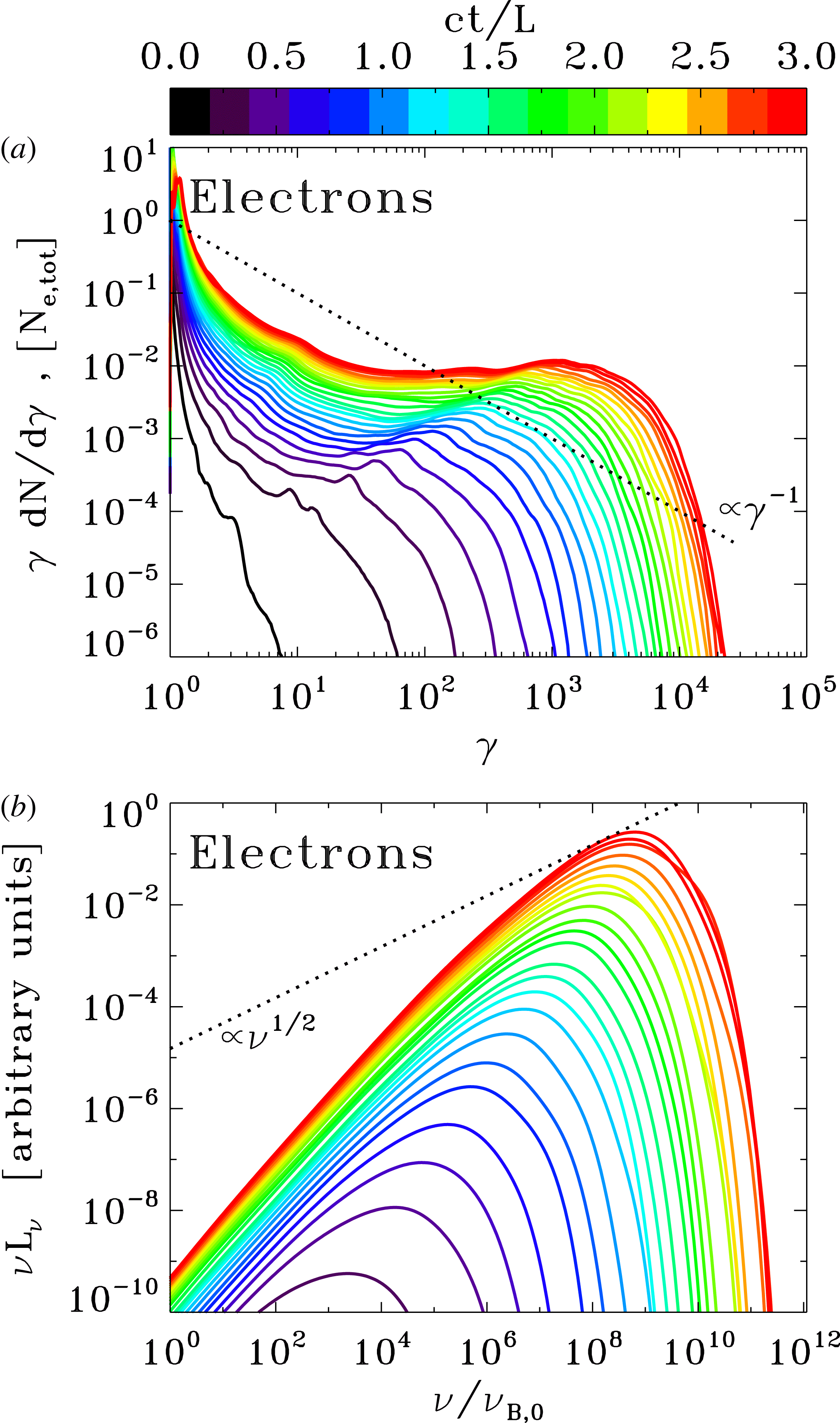
The temporal evolution of the electron energy spectrum is presented in figure 15(a), for a simulation with
 $\unicode[STIX]{x1D70E}_{L}=4\times 10^{2}$
. As the spectral cutoff grows as
$\unicode[STIX]{x1D70E}_{L}=4\times 10^{2}$
. As the spectral cutoff grows as
 $\unicode[STIX]{x1D6FE}_{\max }\propto t^{2}$
(see also the inset in figure 13
c), the spectrum approaches a hard power law
$\unicode[STIX]{x1D6FE}_{\max }\propto t^{2}$
(see also the inset in figure 13
c), the spectrum approaches a hard power law
 $\unicode[STIX]{x1D6FE}\,\text{d}N/\text{d}\unicode[STIX]{x1D6FE}\propto \text{const}.$
The measured spectral slope is consistent with the asymptotic power-law index obtained in the limit of high magnetizations from PIC simulations of relativistic plane-parallel reconnection (Sironi & Spitkovsky Reference Sironi and Spitkovsky2014; Guo et al.
Reference Guo, Liu, Daughton and Li2015; Werner et al.
Reference Werner, Uzdensky, Cerutti, Nalewajko and Begelman2016). Due to energy conservation, such hard slopes would not allow the spectrum to extend much beyond the instantaneous value of the magnetization just upstream of the current sheet (as we have explained before, in our set-up the magnetization at the current sheet increases quadratically with time, since
$\unicode[STIX]{x1D6FE}\,\text{d}N/\text{d}\unicode[STIX]{x1D6FE}\propto \text{const}.$
The measured spectral slope is consistent with the asymptotic power-law index obtained in the limit of high magnetizations from PIC simulations of relativistic plane-parallel reconnection (Sironi & Spitkovsky Reference Sironi and Spitkovsky2014; Guo et al.
Reference Guo, Liu, Daughton and Li2015; Werner et al.
Reference Werner, Uzdensky, Cerutti, Nalewajko and Begelman2016). Due to energy conservation, such hard slopes would not allow the spectrum to extend much beyond the instantaneous value of the magnetization just upstream of the current sheet (as we have explained before, in our set-up the magnetization at the current sheet increases quadratically with time, since
 $B(t)\propto t$
), in line with the arguments of Sironi & Spitkovsky (Reference Sironi and Spitkovsky2014) and Werner et al. (Reference Werner, Uzdensky, Cerutti, Nalewajko and Begelman2016).
$B(t)\propto t$
), in line with the arguments of Sironi & Spitkovsky (Reference Sironi and Spitkovsky2014) and Werner et al. (Reference Werner, Uzdensky, Cerutti, Nalewajko and Begelman2016).
Particle momentum spectrum and anisotropy of the synchrotron spectrum from a PIC simulation of stressed X-point collapse with vanishing guide field and
 $\unicode[STIX]{x1D70E}_{L}=4\times 10^{2}$
. (a) Electron momentum spectrum at the final time
$\unicode[STIX]{x1D70E}_{L}=4\times 10^{2}$
. (a) Electron momentum spectrum at the final time
 $ct/L=3$
along different directions, as indicated in the legend. The total momentum spectrum (i.e. independent of direction) is indicated with a solid black line for comparison. The highest-energy electrons are beamed along the direction
$ct/L=3$
along different directions, as indicated in the legend. The total momentum spectrum (i.e. independent of direction) is indicated with a solid black line for comparison. The highest-energy electrons are beamed along the direction
 $x$
of the reconnection outflow (blue lines) and along the direction
$x$
of the reconnection outflow (blue lines) and along the direction
 $-z$
of the accelerating electric field (red dashed line; positrons will be beamed along
$-z$
of the accelerating electric field (red dashed line; positrons will be beamed along
 $+z$
, due to the opposite charge). The inset shows the 1-D profile along
$+z$
, due to the opposite charge). The inset shows the 1-D profile along
 $x$
of the bulk four-velocity in the outflow direction (i.e. along
$x$
of the bulk four-velocity in the outflow direction (i.e. along
 $x$
), measured at
$x$
), measured at
 $y=0$
. (b) Synchrotron spectrum at the final time
$y=0$
. (b) Synchrotron spectrum at the final time
 $ct/L=3$
along different directions (within a solid angle of
$ct/L=3$
along different directions (within a solid angle of
 $\unicode[STIX]{x0394}\unicode[STIX]{x1D6FA}/4\unicode[STIX]{x03C0}\sim 3\times 10^{-3}$
), as indicated in the legend. The resulting anisotropy of the synchrotron emission is consistent with the particle anisotropy illustrated in (a).
$\unicode[STIX]{x0394}\unicode[STIX]{x1D6FA}/4\unicode[STIX]{x03C0}\sim 3\times 10^{-3}$
), as indicated in the legend. The resulting anisotropy of the synchrotron emission is consistent with the particle anisotropy illustrated in (a).
Dependence of the electron energy spectrum on the magnetization, for three values of
 $\unicode[STIX]{x1D70E}_{L}$
(same values and colour coding as in figure 13) and vanishing guide field:
$\unicode[STIX]{x1D70E}_{L}$
(same values and colour coding as in figure 13) and vanishing guide field:
 $\unicode[STIX]{x1D70E}_{L}=4\times 10^{2}$
(blue),
$\unicode[STIX]{x1D70E}_{L}=4\times 10^{2}$
(blue),
 $\unicode[STIX]{x1D70E}_{L}=4\times 10^{3}$
(green) and
$\unicode[STIX]{x1D70E}_{L}=4\times 10^{3}$
(green) and
 $\unicode[STIX]{x1D70E}_{L}=4\times 10^{4}$
(red). All the spectra are computed at
$\unicode[STIX]{x1D70E}_{L}=4\times 10^{4}$
(red). All the spectra are computed at
 $ct/L=1.8$
. At high magnetizations, two components can be seen in the spectrum: a steep low-energy component and a hard high-energy population that can be fitted as
$ct/L=1.8$
. At high magnetizations, two components can be seen in the spectrum: a steep low-energy component and a hard high-energy population that can be fitted as
 $\unicode[STIX]{x1D6FE}\,\text{d}N/\text{d}\unicode[STIX]{x1D6FE}\propto \unicode[STIX]{x1D6FE}^{1/2}$
(black dotted line). The red dashed line is the particle spectrum for
$\unicode[STIX]{x1D6FE}\,\text{d}N/\text{d}\unicode[STIX]{x1D6FE}\propto \unicode[STIX]{x1D6FE}^{1/2}$
(black dotted line). The red dashed line is the particle spectrum for
 $\unicode[STIX]{x1D70E}_{L}=4\times 10^{4}$
at the same time as the red solid line, but including only the particles located in regions where
$\unicode[STIX]{x1D70E}_{L}=4\times 10^{4}$
at the same time as the red solid line, but including only the particles located in regions where
 $E>B$
.
$E>B$
.
However, we find evidence for a possible solution of this ‘energy crisis’. In figure 17, we explore the dependence of the particle energy spectrum on the magnetization at
 $ct/L=1.8$
, in the case of vanishing guide field. We find that at high
$ct/L=1.8$
, in the case of vanishing guide field. We find that at high
 $\unicode[STIX]{x1D70E}_{L}$
the population of accelerated particles is composed of two components, separated by a break energy (for the red solid curve corresponding to
$\unicode[STIX]{x1D70E}_{L}$
the population of accelerated particles is composed of two components, separated by a break energy (for the red solid curve corresponding to
 $\unicode[STIX]{x1D70E}_{L}=4\times 10^{4}$
in figure 17, the break occurs at a Lorentz factor
$\unicode[STIX]{x1D70E}_{L}=4\times 10^{4}$
in figure 17, the break occurs at a Lorentz factor
 $\unicode[STIX]{x1D6FE}\sim 200$
): a low-energy soft component, whose spectral slope is slightly steeper than
$\unicode[STIX]{x1D6FE}\sim 200$
): a low-energy soft component, whose spectral slope is slightly steeper than
 $\unicode[STIX]{x1D6FE}\,\text{d}N/\text{d}\unicode[STIX]{x1D6FE}\propto \unicode[STIX]{x1D6FE}^{-1}$
(corresponding to equal energy content per decade)Footnote
8
; and a high-energy hard population, with
$\unicode[STIX]{x1D6FE}\,\text{d}N/\text{d}\unicode[STIX]{x1D6FE}\propto \unicode[STIX]{x1D6FE}^{-1}$
(corresponding to equal energy content per decade)Footnote
8
; and a high-energy hard population, with
 $\unicode[STIX]{x1D6FE}\,\text{d}N/\text{d}\unicode[STIX]{x1D6FE}\propto \unicode[STIX]{x1D6FE}^{1/2}$
(so, with the highest energy particles dominating both the number and the energy census). The presence of the soft component, whose energy per particle is significantly lower than the average energy (namely, of the local magnetization), allows the high-energy component to stretch to higher energies, potentially offsetting the energy crisis.
$\unicode[STIX]{x1D6FE}\,\text{d}N/\text{d}\unicode[STIX]{x1D6FE}\propto \unicode[STIX]{x1D6FE}^{1/2}$
(so, with the highest energy particles dominating both the number and the energy census). The presence of the soft component, whose energy per particle is significantly lower than the average energy (namely, of the local magnetization), allows the high-energy component to stretch to higher energies, potentially offsetting the energy crisis.
The two sub-populations have different origins: by tracking individual particles, we find that the soft component is dominated by particles belonging to secondary plasmoids, that are accelerated during plasmoid mergers; in contrast, the hard component is populated by particles that are accelerated by the strong electric fields of the charged-starved regions with
 $E>B$
, and are nearly unaffected by the presence of secondary plasmoids. In fact, the spectrum of the particles located in
$E>B$
, and are nearly unaffected by the presence of secondary plasmoids. In fact, the spectrum of the particles located in
 $E>B$
regions, presented in figure 17 with a dashed red line, only shows the hard component.
$E>B$
regions, presented in figure 17 with a dashed red line, only shows the hard component.
Our simulations of X-point collapse in the presence of a non-zero guide field provide further support to this conclusion. At early times, when no secondary plasmoids are present (in fact, the guide field suppresses the secondary tearing mode), particle energization can only occur via direct acceleration by the charge-starved electric fields in
 $\boldsymbol{E}\boldsymbol{\cdot }\boldsymbol{B}\neq 0$
regions. At these times, only the hard component with
$\boldsymbol{E}\boldsymbol{\cdot }\boldsymbol{B}\neq 0$
regions. At these times, only the hard component with
 $\unicode[STIX]{x1D6FE}\,\text{d}N/\text{d}\unicode[STIX]{x1D6FE}\propto \unicode[STIX]{x1D6FE}^{1/2}$
appears in the corresponding particle spectrum (not shown). At later times, when the guide field at the current sheet becomes sub-dominant with respect to the in-plane fields, secondary plasmoids can be generated, and an additional soft component appears in the particle spectrum.
$\unicode[STIX]{x1D6FE}\,\text{d}N/\text{d}\unicode[STIX]{x1D6FE}\propto \unicode[STIX]{x1D6FE}^{1/2}$
appears in the corresponding particle spectrum (not shown). At later times, when the guide field at the current sheet becomes sub-dominant with respect to the in-plane fields, secondary plasmoids can be generated, and an additional soft component appears in the particle spectrum.
We conclude by analysing the anisotropy of the particle distribution, for
 $\unicode[STIX]{x1D70E}_{L}=4\times 10^{2}$
. In figure 16(a), we plot the electron momentum spectrum at the final time
$\unicode[STIX]{x1D70E}_{L}=4\times 10^{2}$
. In figure 16(a), we plot the electron momentum spectrum at the final time
 $ct/L=3$
along different directions, as indicated in the legend. The particle distribution is significantly anisotropic. The highest-energy electrons are beamed along the direction
$ct/L=3$
along different directions, as indicated in the legend. The particle distribution is significantly anisotropic. The highest-energy electrons are beamed along the direction
 $x$
of the reconnection outflow (blue lines) and along the direction
$x$
of the reconnection outflow (blue lines) and along the direction
 $-z$
of the accelerating electric field (red dashed line; positrons will be beamed along
$-z$
of the accelerating electric field (red dashed line; positrons will be beamed along
 $+z$
, due to the opposite charge). This is consistent with earlier PIC simulations of plane-parallel reconnection in a small computational box, where the X-point acceleration phase was still appreciably imprinting the resulting particle anisotropy (Cerutti et al.
Reference Cerutti, Werner, Uzdensky and Begelman2012b
, Reference Cerutti, Werner, Uzdensky and Begelman2013, Reference Cerutti, Werner, Uzdensky and Begelman2014; Kagan, Nakar & Piran Reference Kagan, Nakar and Piran2016). In contrast, plane-parallel reconnection in larger computational domains generally leads to quasi-isotropic particle distributions (Sironi & Spitkovsky Reference Sironi and Spitkovsky2014). In our set-up of a large-scale X-point, we would expect the same level of strong anisotropy measured in small-scale X-points of plane-parallel reconnection, as indeed demonstrated in figure 16(a). Most of the anisotropy is to be attributed to the ‘kinetic beaming’ discussed by Cerutti et al. (Reference Cerutti, Werner, Uzdensky and Begelman2012b
), rather than beaming associated with the bulk motion (which is only marginally relativistic, see the inset in figure 16
a).
$+z$
, due to the opposite charge). This is consistent with earlier PIC simulations of plane-parallel reconnection in a small computational box, where the X-point acceleration phase was still appreciably imprinting the resulting particle anisotropy (Cerutti et al.
Reference Cerutti, Werner, Uzdensky and Begelman2012b
, Reference Cerutti, Werner, Uzdensky and Begelman2013, Reference Cerutti, Werner, Uzdensky and Begelman2014; Kagan, Nakar & Piran Reference Kagan, Nakar and Piran2016). In contrast, plane-parallel reconnection in larger computational domains generally leads to quasi-isotropic particle distributions (Sironi & Spitkovsky Reference Sironi and Spitkovsky2014). In our set-up of a large-scale X-point, we would expect the same level of strong anisotropy measured in small-scale X-points of plane-parallel reconnection, as indeed demonstrated in figure 16(a). Most of the anisotropy is to be attributed to the ‘kinetic beaming’ discussed by Cerutti et al. (Reference Cerutti, Werner, Uzdensky and Begelman2012b
), rather than beaming associated with the bulk motion (which is only marginally relativistic, see the inset in figure 16
a).
The angle-averaged synchrotron spectrum expected from a relativistic X-point collapse is shown in figure 15(b). For each macro-particle in our PIC simulation, we compute the instantaneous radius of curvature and the corresponding synchrotron emission spectrum. We neglect synchrotron cooling in the particle equations of motion (unlike Cerutti et al.
Reference Cerutti, Werner, Uzdensky and Begelman2013, Reference Cerutti, Werner, Uzdensky and Begelman2014; Kagan et al.
Reference Kagan, Nakar and Piran2016), and we do not consider the effect of synchrotron self-absorption and the Razin suppression at low frequencies. At late times, the synchrotron spectrum approaches a power law with
 $\unicode[STIX]{x1D708}L_{\unicode[STIX]{x1D708}}\propto \unicode[STIX]{x1D708}$
, which just follows from the fact that the electron spectrum is
$\unicode[STIX]{x1D708}L_{\unicode[STIX]{x1D708}}\propto \unicode[STIX]{x1D708}$
, which just follows from the fact that the electron spectrum is
 $\unicode[STIX]{x1D6FE}\,\text{d}N/\text{d}\unicode[STIX]{x1D6FE}\propto \text{const}.$
This is consistent with the spectrum of the Crab flares. The frequency on the horizontal axis is in units of
$\unicode[STIX]{x1D6FE}\,\text{d}N/\text{d}\unicode[STIX]{x1D6FE}\propto \text{const}.$
This is consistent with the spectrum of the Crab flares. The frequency on the horizontal axis is in units of
 $\unicode[STIX]{x1D708}_{B,0}=\sqrt{\unicode[STIX]{x1D70E}_{L}}\unicode[STIX]{x1D714}_{p}/2\unicode[STIX]{x03C0}$
. Given the maximum particle energy in the top panel,
$\unicode[STIX]{x1D708}_{B,0}=\sqrt{\unicode[STIX]{x1D70E}_{L}}\unicode[STIX]{x1D714}_{p}/2\unicode[STIX]{x03C0}$
. Given the maximum particle energy in the top panel,
 $\unicode[STIX]{x1D6FE}_{\max }\sim 10^{4}$
, one would expect the synchrotron spectrum to cutoff at
$\unicode[STIX]{x1D6FE}_{\max }\sim 10^{4}$
, one would expect the synchrotron spectrum to cutoff at
 $\unicode[STIX]{x1D708}_{\max }\sim \unicode[STIX]{x1D6FE}_{\max }^{2}\unicode[STIX]{x1D708}_{B,0}\sim 10^{8}\unicode[STIX]{x1D708}_{B,0}$
, as indeed confirmed in the bottom panel. Figure 16(b) shows the synchrotron spectrum at the final time
$\unicode[STIX]{x1D708}_{\max }\sim \unicode[STIX]{x1D6FE}_{\max }^{2}\unicode[STIX]{x1D708}_{B,0}\sim 10^{8}\unicode[STIX]{x1D708}_{B,0}$
, as indeed confirmed in the bottom panel. Figure 16(b) shows the synchrotron spectrum at the final time
 $ct/L=3$
along different directions (within a solid angle of
$ct/L=3$
along different directions (within a solid angle of
 $\unicode[STIX]{x0394}\unicode[STIX]{x1D6FA}/4\unicode[STIX]{x03C0}\sim 3\times 10^{-3}$
), as indicated in the legend. The resulting anisotropy of the synchrotron emission is consistent with the particle anisotropy illustrated in figure 16(a). In addition, one can see that the resulting synchrotron spectrum along the direction
$\unicode[STIX]{x0394}\unicode[STIX]{x1D6FA}/4\unicode[STIX]{x03C0}\sim 3\times 10^{-3}$
), as indicated in the legend. The resulting anisotropy of the synchrotron emission is consistent with the particle anisotropy illustrated in figure 16(a). In addition, one can see that the resulting synchrotron spectrum along the direction
 $-z$
of the accelerating electric field (dashed red line) appears even harder than the spectrum along
$-z$
of the accelerating electric field (dashed red line) appears even harder than the spectrum along
 $x$
or
$x$
or
 $y$
.
$y$
.
5 Discussion and conclusions
In highly magnetized plasma, the collapse of a uniformly compressed X-point proceeds very rapidly, on the light crossing time of the configuration. As a result, the collapse cannot be described using classical quasi-static approach and the generated electric field is of the order of the magnetic one. In the framework of force-free electrodynamics, we find that without guide field, the X-point immediately develops a singularity – collapses into a current sheet bounded by two Y-points, which fly away at the speed of light. With guide field, the development of singularities is delayed and the initial phase of the collapse can be described analytically. We have shown that for the central region of the X-point, where the guide field strength exceeds that of the in-plane magnetic field, the problem reduces to a single ODE for the squeeze parameter and we have found a simple asymptotic solution to this equation. The solution describes a systematic increase of this parameter, thus indicating that in highly magnetized plasma X-points remain unstable to collapse. This conclusion is confirmed by the results of computer simulations, both force free and PIC.
The force-free and PIC simulations agree very well until the point where the development of strong electric field leads to a breakdown of the force-free approximation near the plane of the collapse. Before this point, the plasma kinetic effects are weak and the evolution is totally controlled by the large-scale magnetic stresses. After this point, the kinetic effects become increasingly important in determining the current sheet structure and its feedback to the surrounding electromagnetic field. Although qualitatively, and in many ways quantitatively, the force-free and PIC solutions remain similar, a number of differences become manifest. For example, in the PIC simulations the current sheet develops magnetic islands (plasmoids) whereas the force-free current sheet remains rather featurelessFootnote 9 .
As the current sheet expands into the region where the guide field is week, its evolution becomes self-similar. This is observed both in the force-free and PIC simulations. Without a guide field, the transition to this regime is very quick. In PIC simulations this occurs as soon as the length of the current sheet significantly exceeds the skin depth. In the self-similar regime, the macroscopic distribution of the magnetic and electric fields around the current sheet remains unchanged but the field strengths scale with the size of the current sheet, which increases at almost the speed of light. Hence the strength of average electric and magnetic fields in the reconnecting region grows linearly with time, whereas the overall reconnection rate remains unchanged.
We find that as
 $\unicode[STIX]{x1D70E}$
increases the reconnection rate approaches the speed of light on a macroscopic scale. This is in contrast with the previous PIC simulations of magnetic reconnection where such high rates have been seen only on the microscopic scales. The large macroscopic stresses typical for the collapsing X-point configuration appear to be the main factor behind the increase. As the strength of the magnetic field brought into the reconnection zone grows linearly with time, so does the strength of the reconnection electric field. This allows the maximum energy of accelerated particles to increase as
$\unicode[STIX]{x1D70E}$
increases the reconnection rate approaches the speed of light on a macroscopic scale. This is in contrast with the previous PIC simulations of magnetic reconnection where such high rates have been seen only on the microscopic scales. The large macroscopic stresses typical for the collapsing X-point configuration appear to be the main factor behind the increase. As the strength of the magnetic field brought into the reconnection zone grows linearly with time, so does the strength of the reconnection electric field. This allows the maximum energy of accelerated particles to increase as
 $\propto t^{2}$
.
$\propto t^{2}$
.
Particle acceleration is a self-consistent by-product of the X-point collapse. Regardless of whether or not a guide field is present in the initial configuration, the highest-energy particles are injected into the acceleration process in charged-starved regions (i.e. where
 $\boldsymbol{E}\boldsymbol{\cdot }\boldsymbol{B}\neq 0$
in the case with guide field, or where
$\boldsymbol{E}\boldsymbol{\cdot }\boldsymbol{B}\neq 0$
in the case with guide field, or where
 $E>B$
for zero guide field), and energized via direct acceleration by the reconnection electric field. As a result, the maximum particle energy does increase as
$E>B$
for zero guide field), and energized via direct acceleration by the reconnection electric field. As a result, the maximum particle energy does increase as
 $\propto t^{2}$
. While secondary plasmoids are continuously generated in the current sheet (in the cases with guide field, at sufficiently late times), in our set-up they are not instrumental for the acceleration of the highest-energy particles. The high-energy part of the spectrum is hard, with power-law slope even harder than
$\propto t^{2}$
. While secondary plasmoids are continuously generated in the current sheet (in the cases with guide field, at sufficiently late times), in our set-up they are not instrumental for the acceleration of the highest-energy particles. The high-energy part of the spectrum is hard, with power-law slope even harder than
 $-1$
, and populated by highly anisotropic particles, beamed primarily along the direction of the accelerating electric field.
$-1$
, and populated by highly anisotropic particles, beamed primarily along the direction of the accelerating electric field.
The hard high-energy tail can be problematic if it includes a large fraction of the accelerated particles as in this case the particle energy is limited by the mean magnetization
 $\unicode[STIX]{x1D70E}$
of plasma brought into the reconnection zone. This would require unrealistic
$\unicode[STIX]{x1D70E}$
of plasma brought into the reconnection zone. This would require unrealistic
 $\unicode[STIX]{x1D70E}\approx 10^{10}$
in order to explain Crab’s flares. However, as soon as the secondary plasmoids are formed in the current sheet, we observe an emergence of the second population of the accelerated particles. These particles are trapped inside the plasmoids, they are accelerated mostly during plasmoid mergers and their spectrum is significantly softer. By the end of our simulations, the number of particles trapped in the plasmoids exceeds that of the hard-energy tail by several orders of magnitude, thus indicating the possible route of resolving this kind of
$\unicode[STIX]{x1D70E}\approx 10^{10}$
in order to explain Crab’s flares. However, as soon as the secondary plasmoids are formed in the current sheet, we observe an emergence of the second population of the accelerated particles. These particles are trapped inside the plasmoids, they are accelerated mostly during plasmoid mergers and their spectrum is significantly softer. By the end of our simulations, the number of particles trapped in the plasmoids exceeds that of the hard-energy tail by several orders of magnitude, thus indicating the possible route of resolving this kind of
 $\unicode[STIX]{x1D70E}$
-problem. Unfortunately, due to the computational limitations we have not been able to reach the particle energies
$\unicode[STIX]{x1D70E}$
-problem. Unfortunately, due to the computational limitations we have not been able to reach the particle energies
 $\unicode[STIX]{x1D6FE}\approx 10^{10}$
typical for the Crab flares. Additional studies are needed to clarify this issue.
$\unicode[STIX]{x1D6FE}\approx 10^{10}$
typical for the Crab flares. Additional studies are needed to clarify this issue.
Since magnetic X-points are unstable to collapse, this brings about the question of how they can be formed in the first place. We cannot exclude that static macroscopic configurations of the sort can be maintained in controlled laboratory experiments, but they are most unlikely to be found in highly dynamic conditions of astrophysical plasma. Here we studied this configuration as an example of a system where large-scale magnetic stresses drive magnetic reconnection and dictate its rate. In the second paper of the series, we consider another artificial example of initially steady-state configuration, the so-called ABC magnetic structure. This periodic configuration has local macroscopic X-points. We find that this configuration is unstable and that the development of this instability triggers collapse of these X-points in the similar fashion to what we described here. This result suggests that highly magnetized plasma configurations are generally unstable and exist mainly in the state of rapid restructuring on the light crossing time. During this restructuring, macroscopic stresses drive magnetic reconnection, causing local magnetic dissipation and acceleration of non-thermal particles. In the final paper of the series, we no longer consider a static initial configuration but study a collision of magnetic current tubes. Such a collision is also accompanied by development of X-points (highly compressed ones) and also leads to magnetic reconnection driven by macroscopic magnetic stresses. Thus, it seems that we are dealing with a rather general phenomenon which may have important applications in relativistic astrophysics.
Acknowledgements
We would like to thank R. Blandford, K. Nalewajko, D. Uzdensky and J. Zrake for numerous and helpful discussions. The PIC simulations were performed on XSEDE resources under contract no. TG-AST120010, and on NASA High-End Computing (HEC) resources through the NASA Advanced Supercomputing (NAS) Division at Ames Research Center. M.L. would like to thank for hospitality Osservatorio Astrofisico di Arcetri and Institut de Ciencies de l’Espai, where large parts of this work were conducted. S.S.K. thanks Purdue University for hospitality during his sabbatical in 2014. This work had been supported by NASA grant NNX12AF92G, NSF grant AST-1306672 and DoE grant DE-SC0016369. O.P. is supported by the ERC Synergy Grant ‘BlackHoleCam – Imaging the Event Horizon of Black Holes’ (grant 610058). S.S.K. is supported by the STFC grant ST/N000676/1.
Appendix A. Stability of unstressed X-point
The above analytical solution shows that the steady-state X-point solution is kind of unstable. This raises the question of how such configuration can be created in a first place. Indeed, unstable states of a dynamical system cannot be reached via its natural evolution. However, the X-point configuration considered in this analysis occupies the whole space and so is the perturbation that leads to its collapse. In reality, X-points and their perturbations occupy only finite volume and in order to address the stability issue comprehensively one has to study finite size configurations.
In this section we describe the response of X-point to small-scale perturbations studied via force-free simulations. In one of our experiments, we perturbed the steady-state X-point configuration by varying only the
 $x$
-component of the magnetic field:
$x$
-component of the magnetic field:
 $$\begin{eqnarray}\unicode[STIX]{x1D6FF}B_{x}=B_{\bot }\sin (\unicode[STIX]{x03C0}y/L)\exp (-(y/L)^{2}).\end{eqnarray}$$
Obviously, the length scale this perturbation is
 $L$
and to ensure that it is small we select a computational domain whose size is much larger than
$L$
and to ensure that it is small we select a computational domain whose size is much larger than
 $L$
. In this particular case we put
$L$
. In this particular case we put
 $B_{\bot }=L=1$
and use the computational domain
$B_{\bot }=L=1$
and use the computational domain
 $(-6,6)\times (-6,6)$
with 300 cells in each direction. Figure 18 shows the initial configuration and the solution at
$(-6,6)\times (-6,6)$
with 300 cells in each direction. Figure 18 shows the initial configuration and the solution at
 $t=7$
. One can see that the perturbation does not push the X-point away from its steady state. On the contrary, the waves created by the perturbation leave the central area on the light crossing time and the steady-state configuration is restored. Although, here we present the results only for this particular type of perturbation, we have tried several other types and obtained the same outcome. Thus, we conclude that the magnetic X-point is stable to perturbations on a length scale which is much smaller compared to its size, even when the perturbation amplitude is substantial.
$t=7$
. One can see that the perturbation does not push the X-point away from its steady state. On the contrary, the waves created by the perturbation leave the central area on the light crossing time and the steady-state configuration is restored. Although, here we present the results only for this particular type of perturbation, we have tried several other types and obtained the same outcome. Thus, we conclude that the magnetic X-point is stable to perturbations on a length scale which is much smaller compared to its size, even when the perturbation amplitude is substantial.
Stability of the X-point to small-scale perturbations in force-free simulations. (a) Shows the
 $x$
component of the magnetic field along the line
$x$
component of the magnetic field along the line
 $y=0$
. The dashed line corresponds to the initial perturbed solution. The solid line corresponds to the numerical solution at
$y=0$
. The dashed line corresponds to the initial perturbed solution. The solid line corresponds to the numerical solution at
 $t=7$
. (b) Shows the magnetic field lines of the initial solution (dashed lines) and the solution at
$t=7$
. (b) Shows the magnetic field lines of the initial solution (dashed lines) and the solution at
 $t=7$
.
$t=7$
.
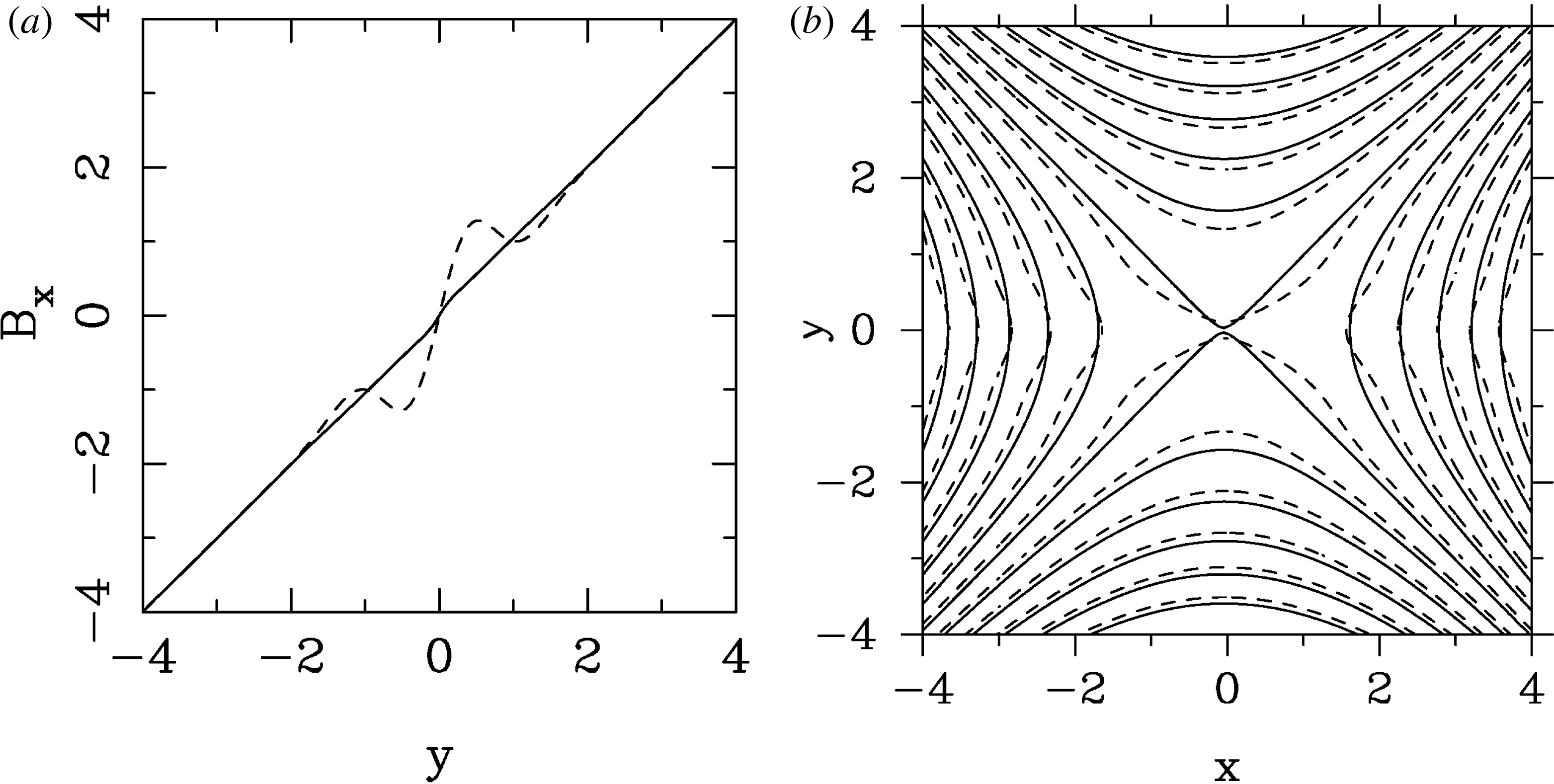
We have also verified the stability of unstressed X-points with PIC simulations. Here, no initial perturbation is imposed on the system. In the standard set-up of anti-parallel reconnection, the system would grow unstable from particle noise. Here, we have demonstrated that an unstressed X-point is stable to noise level fluctuations.