Introduction
Microbial biofilms are able to naturally colonize electrodes and form conductive matrices consisting of living cells and extracellular polymeric substance (EPS) (proteins, sugars, DNA) (for a review, see Ref. Reference Flemming and Wingender1). This phenomenon is well-known and the growth of such biofilms is standard lab practice for research groups in the field of microbial electrochemistry and electromicrobiology.[Reference Yates, Strycharz-Glaven, Golden, Roy, Tsoi, Erickson, El-Naggar, Calabrese Barton and Tender2] Since conductive biofilms have been shown to possess the characteristics of redox conducting polymers,[Reference Snider, Strycharz-Glaven, Tsoi, Erickson and Tender3] we can consider them as biologic materials in order to create new molecules, sensors, and bio-derived materials.[Reference Joshi, Cook and Mannoor4] However, creation of these new materials requires the ability to precisely engineer the living component. Synthetic biology aims to confer design and engineering principles with living organisms, an approach now being implemented to re-engineer natural living conductive biofilms or engineer extracellular electron transfer (EET) pathways into organisms that do not naturally have them. Precise control over microbial EET could enable the use of such materials to address long-standing problems, such as corrosion and biofouling, as well as for new applications such as sensing/reporting with electrical signals,[Reference Zhou, Baruch, Ajo-Franklin and Maharbiz5] increased conductivity for electronic applications,[Reference Zhirnov6] and improved catalysis for power and energy from microbial fuel cells.
Although microbial electrochemical activity was first observed over 100 years ago,[Reference Potter7] and rediscovered in the early 2000s where it grew into the field of microbial electrochemistry, the development of engineered conductive biofilms as living materials has been hampered by the fact that many basic research questions regarding the spatial assembly and organization of electron-transfer mediators and components of EET pathways of these systems remain unanswered. In developing living conductive materials as a technology, we must define the rules that govern our ability to intentionally connect cells to electrodes and to each other. Synthetic biology offers rapidly advancing tools in genetic engineering and, as we establish these rules, we will be able to make fuller use of the entire toolkit. This includes our ability to successfully move electron transport proteins from natural host organisms to those that are genetically tractable or more operationally relevant, such as those with a tolerance for high salinity or extreme pH.
Natural conductive biofilms consist of cells that self-“wire” to electrodes and form protein or protein/small-molecule conduits for electrons to travel directly between the cell and electrode interface, as well as between cells. Our current knowledge of these conduits, which are described briefly below, forms the basis for creating engineered living conductive materials. Natural conductive films are able to self-replicate and self-repair in order to maintain cellular energy flux and growth. This self-repairing property has been exploited for persistent power generation in microbial fuel cells.[Reference Tender, Reimers, Stecher, Holmes, Bond, Lowy, Pilobello, Fertig and Lovley8] Biofilms associated with electrodes serve as living catalysts, mediating electron transfer to and from the electrode surface to catalyze reactions such as the oxidation of acetate (Geobacter sulfurreducens) or to generate energy and reductant for CO2 fixation (“Candidatus Tenderia electrophaga”[Reference Eddie, Wang, Malanoski, Hall, Oh, Heiner, Lin and Strycharz-Glaven9]). In anodic bioelectrochemical systems (BES), where electrons are transferred across the cell membrane to a solid electron acceptor, EET pathways are fairly well-characterized for the gram-negative metal-reducing bacteria, Shewanella oneidensis [Reference Coursolle, Baron, Bond and Gralnick10] and G. sulfurreducens,[Reference Jiménez Otero, Chan and Bond11, Reference Lovley, Ueki, Zhang, Malvankar, Shrestha, Flanagan, Aklujkar, Butler, Giloteaux, Rotaru, Holmes, Franks, Orellana, Risso and Nevin12] and in both cases include a number of multiheme c-type cytochromes to shuttle the electrons from the inner membrane to the outside of the cell. In G. sulfurreducens biofilms, which can be up to tens of micrometers thick, immuno-gold labeling[Reference Stephen, LaBelle, Brantley and Bond13, Reference Leang, Qian, Mester and Lovley14] and confocal resonance Raman microscopy of c-type cytochromes[Reference Lebedev, Strycharz-Glaven and Tender15] have shown that they are located on the cell membrane and in the extracellular matrix outside of the cell. This observation, as well as biofilm conductivity measurements indicating redox hopping,[Reference Yates, Golden, Roy, Strycharz-Glaven, Tsoi, Erickson, El-Naggar, Calabrese Barton and Tender16, Reference Yates, Strycharz-Glaven, Golden, Roy, Tsoi, Erickson, El-Naggar, Barton and Tender17] have substantiated the hypothesis that c-type cytochromes are primarily responsible for electron transfer between cells and from cells to the electrode[Reference Snider, Strycharz-Glaven, Tsoi, Erickson and Tender3, Reference Lebedev, Strycharz-Glaven and Tender15] in living biofilms. Shewanella biofilms are thin and interspersed with outer-membrane extensions (OME) decorated with c-type cytochromes of the Mtr pathway,[Reference Coursolle, Baron, Bond and Gralnick10, Reference Pirbadian, Barchinger, Leung, Byun, Jangir, Bouhenni, Reed, Romine, Saffarini, Shi, Gorby, Golbeck and El-Naggar18, Reference Subramanian, Pirbadian, El-Naggar and Jensen19] which have recently been shown to support a conductive matrix.[Reference Xu, Barrozo, Tender, Krylov and El-Naggar20] In addition, Shewanella secretes redox-active flavins which have a role in EET.[Reference Kotloski and Gralnick21] Conductivity measurements have also been performed on mixed species anodic biofilms which exhibited redox conductivity, however, the underlying mechanism was not explored.[Reference Li, Lesnik, Fan and Liu22] Many mixed species anodic biofilms are enriched in Geobacter spp., all of which contain the genes for c-type cytochromes, so it is often assumed that these are the primary electron-transfer mediators.
Less is known about direct electron transfer in cathodic systems. Although direct electron transfer has been proposed as a mechanism for acetogenic or methanogenic BES used for microbial electrosynthesis,[Reference Lovley23, Reference Rabaey and Rozendal24] it has been difficult to decouple from the possibility that H2 generated at the electrode surface is the electron-transfer mediator due to the negative electrode potentials required to thermodynamically drive CO2 reduction. In one case, it has been demonstrated that electrode-associated enzymes catalyze H2 and formate production at the electrode which then serve as electron donors for methanogenesis.[Reference Deutzmann, Sahin and Spormann25] While acetogenic and methanogenic BES are anaerobic, other cathodic organisms displaying electrochemical characteristics consistent with direct EET are aerobic. Neutrophilic iron-oxidizing bacteria,[Reference Summers, Gralnick and Bond26] as well as certain microbial communities enriched at the cathode of benthic microbial fuel cells, use O2 as the terminal electron acceptor and are proposed to fix CO2 autotrophically through the Calvin–Benson cycle. One such community, Biocathode MCL, has been extensively characterized by our group[Reference Wang, Leary, Malanoski, Li, Hervey, Eddie, Tender, Yanosky, Vora, Tender, Lin and Strycharz-Glaven27–Reference Eddie, Wang, Hervey, Leary, Malanoski, Tender, Lin and Strycharz-Glaven29] and has been demonstrated to create a conductive biofilm matrix containing c-type cytochromes and other redox-active proteins as the primary redox mediators.[Reference Yates, Strycharz-Glaven, Golden, Roy, Tsoi, Erickson, El-Naggar, Barton and Tender17] The most highly active member of the Biocathode MCL community, “Candidatus Tenderia electrophaga” contains a proposed direct EET pathway similar to that of some neutrophilic, autotrophic iron-oxidizing bacteria, although the strain has not yet been cultivated in isolation. Proteins that participate in direct EET in the examples given above reside in the cell membrane, or in the extracellular matrix surrounding the cell, and make direct contact with the electrode surface. We can use synthetic biology to re-engineer these pathways in native and non-native host organisms through the use of protein engineering,[Reference Du, Catania and Bazan30] precise control over transcription using genetic circuits,[Reference Nakamura, Kai, Okamoto, Newton and Hashimoto31] and the use of data generated from metabolic modeling and functional genome analysis of electroactive bacteria to inform machine learning—which could lead to rational design of electron transport pathways. Throughout the rest of this prospective, we will outline key areas we have identified that could transform our ability to create engineered living conductive materials using synthetic biology, including membrane shaping and abiotic/biotic surface modifications that more precisely align cells with the electrode interface, as well as better tools to measure this interaction using a more high-throughput approach to evaluate organisms genetically modified to carry out direct EET on an electrode.
The abiotic/biotic interface
In order to engineer direct electron transfer to an electrode, we must first consider the connection between the cell and the electrode itself. BES are used to grow and assay the electrochemical activity of natural and engineered bacteria using biologically compatible electrode materials. Labs performing microbial electrochemistry use a somewhat shotgun approach to BES design because the contribution from all components of the reactor cannot be fully controlled (pH changes, gas concentrations, small molecules produced by intact or lysed cells, and chemical changes to the composition of the medium due to biological or electrochemical activation). These variations can make it difficult to fully characterize BES—establishing a list of defined mediators and understanding the details of the electrode surface and the biologic interface has been challenging even in the best studied electrochemically active microorganisms. Here we describe what is known and should be considered for BES design moving forward.
Electrode surface composition and cell attachment
Promotion of cell attachment and biofilm formation at the electrode may be two of the most important parameters for increasing current through higher electron-transfer rates.[Reference Du, Catania and Bazan30] Typically, carbon-based electrodes, such as carbon cloth or graphite coupons, are used to evaluate natural EET. In order to obtain maximum current and achieve a high efficiency, the electrode should be porous with a high-surface area to allow for maximum colonization and biofilm production (biocompatibility), while also exhibiting high electrical conductivity and low susceptibility to corrosion. Individual labs typically focus on one specific organism, and a universal high-efficiency electrode material is yet to be discovered. Given the variability in electrochemically active organisms, a universal electrode configuration may not exist.
Surface modifications involving metal oxides or conducting polymers have been incorporated in order to enhance bacterial adhesion or increased EET. In addition, nanostructures, geometries, particle sizes, and chemical composition all affect current production,[Reference Du, Catania and Bazan30] although the mechanism is not always understood. Electrodes coated with metals or metal-based nanoparticles, including gold, palladium, osmium, and nickel, result in increased electron transfer. Nakamura et al.[Reference Nakamura, Kai, Okamoto, Newton and Hashimoto31] increased current production for Shewanella loihica PV-4 over 300-fold compared to an unmodified biofilm by adding α-Fe2O3 nanocolloids to a growing, anaerobic culture, which enhanced biofilm formation and enabled long-distance electron transfer through a conductive network of bacterial cells connected by nanocolloids. A recent review offers a detailed comparison of nanostructured electrode materials.[Reference Zhao, Gai, Song, Chen, Zhang and Zhu32] Although they produce lower current densities due to their smooth surfaces, electrodes made out of gold- or indium tin oxide-coated glass can also support growth of conductive biofilms. Synthetic biology may have a role to play in increasing the rate of EET via modifications to cell surface attachment: several studies have shown that genetic changes can increase biofilm formation and current output in S. oneidensis. Kouzuma et al.[Reference Kouzuma, Oba, Tajima, Hashimoto and Watanabe33] demonstrated that, in a library of random S. oneidensis mutants, those with higher current production also had thicker biofilms, while Liu et al.[Reference Liu, Yu, Deng, Ng, Cao, Wang, Rice, Kjelleberg and Song34] were able to boost current production 2.8-fold by increasing the production of the biofilm-promoting molecule bis-(3′–5′)-cyclic dimeric guanosine monophosphate (cyclic-di-GMP). It is interesting to note, however, that a recent effort to engineer S. oneidensis to bind gold electrodes,[Reference Kane, Bond and Gralnick35] as well as a study in which Escherichia coli expressing the S. oneidensis Mtr pathway were immobilized at the electrode through the expression of mannose binding proteins,[Reference Lienemann, TerAvest, Pitkanen, Stuns, Penttila, Ajo-Franklin and Jantti36] led to increased cell binding but decreased current production relative to the non-binding strains. These studies highlight the complexity of engineering cell–surface interactions. Once these hurdles are overcome, surface attached cells could be programed to organize with more efficient architectures for substrate and product diffusion which could alleviate mass transport limitations to the electrode surface. One way this may be achieved would be for cells to produce nanostructures themselves by coordinating cell-produced nanoparticles and polysaccharides in a directed way.
An additional aspect of BES design that requires consideration for engineering living conductive materials are the pH, temperature, nutrient concentration, and physical arrangement of the electrodes. The former are important from the physiological perspective of the cell, while the latter can impact the overall performance of the BES. Not discussed here, but worth mentioning, is the opportunity to design biologically produced membrane materials to act as separators in microbial fuel cells.
Undefined electron-transfer mediators at the electrode surface
We have defined electron-transfer mediators in this review as proteins fixed in the cell membrane or in the immediate extracellular matrix. It is well-known that many bacteria also produce a variety of soluble mediators that can facilitate electron transfer between the cell and abiotic surface, such as flavins, phenazines, and hydrogenases (though not covered here, recent overviews of soluble redox mediators can be found in Liu et al.[Reference Liu, Shi and Gu37]). In addition to organic (produced by the bacteria) and metal (trace elements in the medium) mediators, redox-active sulfur can potentially cycle between solid and soluble states, effectively trapping it within the biofilm. Initial metagenomics and metatranscriptomics analyses of a recently-characterized reversible BES[Reference Yates, Ma, Sack, Golden, Strycharz-Glaven, Yates and Tender38] suggest that sulfur species may be acting as intermediaries between cells and the electrode, in both oxidizing and reducing functions (Mickol et al., 2019; in preparation). Both sulfate-reducing[Reference Yu, Duan, Zhao, Huang and Hou39, Reference Agostino and Rosenbaum40] and sulfur-oxidizing[Reference Gong, Ebrahim, Feist, Embree, Zhang, Lovley and Zengler41] microorganisms are found in BES, suggesting that sulfur species may operate as electron-transfer mediators. Much of what we know regarding the redox potential of natural electron-transfer mediators is based on voltammetric techniques which have limitations in sensitivity depending on the electrode and potentiostat used. Additionally, voltammetry cannot provide absolute identification of a redox species without control experiments, which are difficult to achieve if redox-active moieties can be produced through biologic transformations inherent to the BES. The potential for microbial transformation of trace elements or metabolic products into redox-active moieties should be considered when designing engineered living conductive materials. In some cases, if such transformations can be elucidated, they may be exploited for biofilm functionalization.
Role of extracellular polymeric substances and broader environment
Bacterial cells are surrounded by the EPS, a network of cell-secreted polymers composed of polysaccharides, proteins, DNA, and redox-active moieties. The EPS contributes to biofilm formation, protects the cell from the environment,[Reference Xiao, Zhang, Zhang, Dai, Yang, Christensen, Ulstrup and Zhao42] and, as has been demonstrated for G. sulfurreducens,[Reference Stephen, LaBelle, Brantley and Bond13, Reference Leang, Qian, Mester and Lovley14] contains EET mediators. The overall role of the EPS in EET has been difficult to decipher due to limitations in our ability to separate out the contribution of each component listed above. Rollefson et al.[Reference Rollefson, Stephen, Tien and Bond43] demonstrated that the G. sulfurreducens xap gene cluster is required to create an EPS rich in c-type cytochromes where it acts as a scaffold for electron-transfer mediators enabling long-range electron transport. Xiao et al.[Reference Xiao, Zhang, Zhang, Dai, Yang, Christensen, Ulstrup and Zhao42] performed electrochemical characterization of S. oneidensis MR-1 containing naturally-produced concentrations of EPS and under conditions where EPS was depleted. Maximum current achieved was 40–90% higher in EPS-depleted cultures and differential pulse voltammetry showed that the EPS layer may shield cell-associated cytochromes from direct contact with the electrode, indicating the EPS may be insulating in Shewanella. Whether the native EPS aids or inhibits the conductivity of a biofilm therefore appears to be organism-specific and dependent on the presence of extracellular redox-active moieties.
These results suggest that the composition of the EPS could be tuned to be more or less conductive. There are, of course, tradeoffs when considering engineered modifications to the EPS. For example, EPS-depleted cells are more susceptible to disruption and surface proteins could be more susceptible to inactivation.[Reference Xiao, Zhang, Zhang, Dai, Yang, Christensen, Ulstrup and Zhao42]
Making connections—membrane shaping
Thus far, we have considered the role of the extracellular space between the electrode and the cell. However, the cell membrane is the connection between the energy generating processes of the cell and the extracellular matrix and its architecture has an unknown impact on direct EET.
In living organisms, electron-transfer reactions are mediated by proteins embedded in complex membrane structures, from the folds of mitochondrial cristae,[Reference Wittig, Carrozzo, Santorelli and Schagger44] to cyanobacterial thylakoid membranes,[Reference Rexroth, Mullineaux, Ellinger, Sendtko, Rogner and Koenig45] and even to structures that extend out from the cell in the case of S. oneidensis.[Reference Pirbadian, Barchinger, Leung, Byun, Jangir, Bouhenni, Reed, Romine, Saffarini, Shi, Gorby, Golbeck and El-Naggar18, Reference Subramanian, Pirbadian, El-Naggar and Jensen19] The membrane compartmentalizes electron-transfer proteins into hydrophilic and hydrophobic fractions, where soluble mediators carry charge from the hydrophilic fraction to transmembrane complexes. In thylakoid membranes and mitochondrial cristae, membrane curvature is suspected to influence the rate of diffusion-limited electron-transfer reactions by affecting the localization of soluble and membrane-bound cytochromes.[Reference Kirchhoff46–Reference Kirchhoff48] Recently, cristae membrane morphology has shown to have a direct impact on mitochondrial respiratory function, where increased curvature, and by extension, increased inner membrane surface area, were associated with higher respiratory efficiency.[Reference Cogliati, Frezza, Soriano, Varanita, Quintana-Cabrera, Corrado, Cipolat, Costa, Casarin, Gomes, Perales-Clemente, Salviati, Fernandez-Silva, Enriquez and Scorrano49] Both mitochondrial cristae and thylakoid membrane structures display localized regions of tightly packed electron-transfer protein clustering,[Reference Kirchhoff46] suggesting that compartmentalization of electron-transfer proteins/complexes through membrane curvature formation is a common feature of bioenergetic membranes and may improve electron-transfer efficiency.
In bacteria that form living conductive biofilms, OMEs could impact the spatial arrangement of EET protein conduits altering the rate of EET with the extracellular environment or periplasmic mediators. S. oneidensis OMEs are comprised of the outer membrane and periplasm, and progress from elongated vesicle chains into narrow tubules decorated with membrane-bound EET proteins.[Reference Pirbadian, Barchinger, Leung, Byun, Jangir, Bouhenni, Reed, Romine, Saffarini, Shi, Gorby, Golbeck and El-Naggar18, Reference Subramanian, Pirbadian, El-Naggar and Jensen19] Although the contribution of these OMEs to the overall conductivity of S. oneidensis biofilms is not known, reductase activity from proteins of the Mtr pathway has been observed suggesting they are still able to facilitate EET. A qualitatively similar membrane structure has been observed in cultures of sulfate-reducing bacteria, which have been shown to produce conductive nanofilaments when no soluble electron acceptor was added.[Reference Eaktasang, Kang, Lim, Kwean, Cho, Kim and Kim50]
Although the genetic basis of OME biogenesis in Shewanella is currently not known, identification of membrane sculpting proteins could be used to initiate OME formation. Control over membrane shape could enable directed biofilm structural control through the use of optimized small-molecule sensors[Reference Meyer, Segall-Shapiro, Glassey, Zhang and Voigt51] for tunable protein expression. Additionally, cell–cell or cell–electrode membrane contact could be designed for programed self-healing in engineered living conductive materials. For example, a sudden shift in the biofilm redox gradient could be sensed (described below) and trigger expression of membrane extension-promoting proteins, signaling cells to reestablish a membrane tether to neighboring cells.
Electron-transfer conduits, potential sensors, and chassis strains
As discussed above, the cell membrane is the point of contact between the metabolic processes of the cell and the extracellular environment. Our current state of understanding of bacterial EET is that electron-transfer conduits made of c-type cytochromes reside within the outer membrane of gram-negative bacteria and can make direct contact with the electrode and to redox mediators of neighboring cells, creating a living conductive material. One of these pathways has been heterologously expressed in E. coli (described below), demonstrating that they are portable and that the tools of synthetic biology could be used to design and engineer living conductive materials. In addition to EET conduits, membrane-bound sensors that can detect a change in the surface potential of the electrode may exist although none have been demonstrated to date. Here, we describe our current understanding of engineering EET pathways into non-native hosts for both anodic (outward) EET and cathodic (inward) EET, as well as the potential to develop electrode surface potential sensors that can directly actuate cellular response to a change in applied potential at the electrode.
Controlling EET pathways with synthetic biology
The transfer of functional EET pathways to heterologous hosts presents significant challenges. Although there are common themes emerging in the various EET pathways studied (Fig. 1), these pathways often consist of proteins and complexes that have multiple cofactors, must be localized correctly, operate in complexes and pathways that depend on the proper protein ratios, and are all too often insufficiently understood to rapidly and reliably port to new organisms. To date, the primary EET pathway used for engineering has been the anodic Mtr pathway from S. oneidensis MR-1 which allows for extracellular respiration of metals. The Mtr pathway is the best studied of the EET pathways, with the primary components known: electrons travel through a tetraheme cytochrome in the inner membrane (CymA), via a small tetraheme cytochrome in the periplasm (CctA) to the outer membrane, where they pass through a multiheme cytochrome-porin complex (MtrCAB) to the extracellular space, where they are transferred to a solid or soluble electron acceptor.[Reference Hartshorne, Reardon, Ross, Nuester, Clarke, Gates, Mills, Fredrickson, Zachara and Shi52, Reference TerAvest and Ajo-Franklin53] Some success has been shown both in control of the Mtr pathway in its native host[Reference West, Jain and Gralnick54] as well as in E. coli.[Reference TerAvest, Zajdel and Ajo-Franklin55] However, though successful, the work in E. coli shows that transferring this pathway to a heterologous host is not trivial. The system requires a great deal of optimization,[Reference Jensen, TerAvest, Kokish and Ajo-Franklin56–Reference Jensen, Albers, Malley, Londer, Cohen, Helms, Weigele, Groves and Ajo-Franklin58] at least in E. coli: separate expression of the E. coli’s cytochrome c maturation pathway proteins, the addition of a cytochrome c maturation protein from the Shewanella pathway, and specific ratios of the proteins from the Mtr pathway, are all required for maximum current production. Even when optimized this system does not form a stable BES; the cells must be grown and induced, then added to the electrochemical reactor at high density. Our own work has shown that transferring the pathway into a new host (Marinobacter in this case) produces inconsistent results (Fig. 2)—suggesting that significant optimization will be required for each new host organism. These difficulties are not too surprising, considering the complexity of the proteins themselves. Four of the five proteins required are multiheme c-type cytochromes, which require specialized machinery to correctly process; the overexpression of five EET proteins, as well as the heme maturation pathway, can reasonably be expected to come at a metabolic cost. Additionally, the MtrCAB conduit must not only be correctly localized to the periplasm for cytochrome maturation, but must further be targeted to the outer membrane, using localization signals that are not well understood and may or may not be easily transferable between bacterial species. Given these complications, successfully transferring the Mtr pathway as an efficient pathway for electron flow in heterologous hosts is a significant challenge.
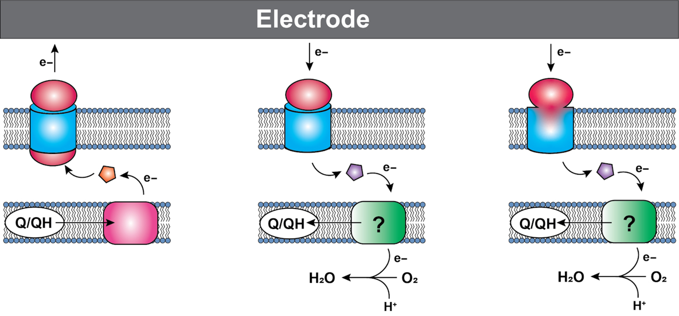
General configuration of various electron conduits. Cytochromes are shown in red/pink/orange, membrane porins are shown in blue, and proteins that vary depending on the pathway are shown in purple. The green boxes denote variable and poorly understood acceptors. Anodic conduits (left) in both Shewanella and Geobacter consist of a cytochrome in the inner membrane that accepts electrons from the quinone pool, and transfers them to a soluble periplasmic cytochrome, which transfers them to a multiprotein cytochrome/porin complex. The number of proteins in the complex is variable depending on the organisms and specific conduit. Some cathodic organisms use a similar outer-membrane complex (middle), with a multiheme cytochrome and porin, though whether all the components of these complexes have been identified is unclear. From there, the electrons pass to a soluble membrane carrier, which can be a cytochrome, iron sulfur protein, or copper containing protein. Finally, a potentially more widespread system consists of a fused monoheme porin protein (right), which also makes use of a soluble electron carrier to deliver electrons to the inner membrane. The path that electrons take once they leave the outer-membrane mediator varies among organisms, and is in many cases incompletely understood.
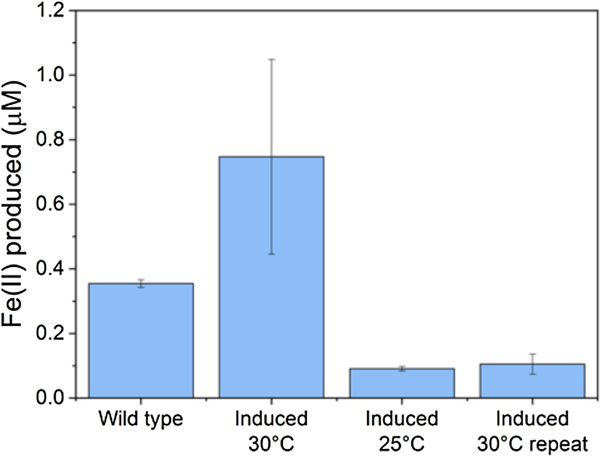
Iron reduction in wild-type versus engineered Marinobacter atlanticus CP1 cells. M. atlanticus CP1 was engineered to contain the MtrCAB operon under isopropyl β-d-1-thiogalactopyranoside (IPTG) induction in single copy on the chromosome, and CymA and CctA under 2,4-diacetylphloroglucinol (DAPG) induction on a plasmid. Cells were pre-grown in artificial seawater medium with 50 mM lactate, and diluted 1:5 into fresh medium with 50 mM lactate, 10 µM IPTG, and 250 nM DAPG in balch tubes with 1 mM iron(III)-citrate. The tubes were stoppered and incubated at the indicated temperatures for 48 h. The wild-type control was grown at 30 °C; wild-type cultures at 25 °C showed similar levels of iron reduction. Although in some experiments (induced 30 °C) showed increased iron reduction over the wild type, repeat experiments (induced 25 °C, induced 30 °C repeat) showed lower iron reduction that the wild-type strain, despite having similar cell densities at the end of the experiments. These results suggest that the conditions required for successful expression and operation of the Mtr pathway in Marinobacter is so delicate that slight variations between experiments are enough to upset the balance, and indicates that we have not yet determined the optimal requirements for expression of the Mtr pathway in Marinobacter.

Although the Mtr pathway is the best studied of the anodic EET pathways, it is not the only one. The mechanisms of electron transfer in Geobacter have also been extensively investigated[Reference Jiménez Otero, Chan and Bond11, Reference Leang, Qian, Mester and Lovley14, Reference Liu, Wang, Liu, Levar, Edwards, Babauta, Kennedy, Shi, Beyenal, Bond, Clarke, Butt, Richardson, Rosso, Zachara, Fredrickson and Shi59, Reference Zacharoff, Morrone and Bond60] and recently have proven somewhat similar to those in Shewanella, featuring several multiheme cytochromes and an outer-membrane porin which, though not homologous to those in Shewanella, appear to operate in a similar fashion—indicating the possible significance of porin–cytochrome complexes for EET across multiple species.[Reference TerAvest and Ajo-Franklin53, Reference Costa, Clarke, Philipp, Gescher, Louro and Paquete61] The barriers to successful deployment of the Mtr pathway in heterologous organisms also exist for the Geobacter pathways: multiheme cytochromes which must be correctly processed and localized. However, the ease with which E. coli, at least, expresses various multiheme cytochromes varies depending on the specific protein for reasons that are not entirely understood.[Reference Londer, Giuliani, Peppler and Collart62] It is therefore possible that the use of the Geobacter EET pathway may prove easier, at least for some hosts. Thus far, no studies have been published using the Geobacter proteins in heterologous expression systems to recapitulate EET to an electrode. This may, in part, be due to the fact that the function of the many multiheme proteins present in Geobacter have proven to be redundant with a definitive outer-membrane EET conduit not suggested until recently.[Reference Jiménez Otero, Chan and Bond11]
On the cathodic side, the known pathways can be divided into two general categories: those that include outer-membrane multiheme cytochromes (similar to the anodic pathways), and those that use Cyc2, a small monoheme cytochrome that in a number of iron-oxidizing microbes is fused to an outer-membrane porin.[Reference Talla, Hedrich, Mangenot, Ji, Johnson, Barbe and Bonnefoy63] Homologs of this protein have been found in a number of iron oxidizers, both acidophilic and neutrophilic (Chan, unpublished[Reference Chan, McAllister, Garber, Hallahan and Rozovsky64]). There are examples of iron-oxidizing bacteria with these pathways able to produce cathodic current on electrodes, suggesting that these pathways too can operate with solid substrates.[Reference Summers, Gralnick and Bond26, Reference Bose, Gardel, Vidoudez, Parra and Girguis65] While the smaller size of the monoheme protein may make it easier to express in heterologous hosts, the downstream portion of the pathway is considerably more complicated. Recent proteomic analysis of the neutrophilic microaerobic iron oxidizer Mariprofundus ferrooxydans showed additional inner membrane and periplasmic components, some of them with no homology to known enzymes.[Reference Barco, Emerson, Sylvan, Orcutt, Jacobson Meyers, Ramirez, Zhong and Edwards66] Additionally, putative cathodic EET conduits have been identified from “Ca. Tenderia electrophaga” with similarity to those described for iron-oxidizing bacteria;[Reference Wang, Leary, Malanoski, Li, Hervey, Eddie, Tender, Yanosky, Vora, Tender, Lin and Strycharz-Glaven27–Reference Eddie, Wang, Hervey, Leary, Malanoski, Tender, Lin and Strycharz-Glaven29] however, this pathway has yet to be experimentally validated. Since many of the organisms in question are lithotrophs, surviving on an electron donor more oxidized than the organic carbon fixed by the cell, a bifurcation is required, in which electrons traveling to oxygen or nitrate provide energy for a reverse electron-transfer chain. The extent to which the autotroph-based oxidation pathways can be repurposed in heterotrophs remains to be seen.
Cellular sensing of the electrode potential
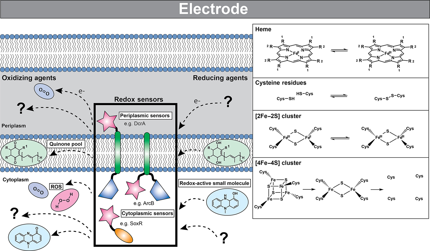
Microorganisms sense and respond to the redox state of their environment via redox sensors; proteins that when oxidized or reduced produce a cellular response through mechanisms such as transcription or taxis. Microbial redox sensors characterized to date are either integral to the plasma membrane (with either periplasmic or cytoplasmic sensing domains) or are located in the cytosol (Fig. 3). The sensing domain interacts with redox-active small molecules (e.g., pyridine nucleotides (NAD(H), NADP(H)), quinones, oxygen, hydrogen peroxide, and superoxide) via cofactors such as iron–sulfur clusters, hemes, protein thiols, and flavins (FAD, FMN).[Reference Green and Paget67] As described below, these sensors can be either one- or two-component systems that interact with DNA directly to elicit a response or transmit a signal to downstream protein partners. To date, no redox sensor has been described that can detect the potential of an electrode or other extracellular electron acceptors through direct electron transfer from an EET conduit. All characterized redox sensors depend on soluble mediators as a proxy for the redox state of the cell and periplasm.
Cells can detect redox changes using both one- and two-component systems via sensor domains residing in either the intracellular or periplasmic space. These sensor domains contain redox-active moieties such as hemes, disulfide bond-forming cysteine residues, and iron–sulfur clusters that are sensitive to a variety of oxidizing and reducing agents. The reduced (left) and oxidized (right) forms of these redox-active moieties are shown in the inset. The loss of the iron–sulfur cluster is indicated by the unligated protein cysteine residues. In many cases, the identities of the physiological oxidizing and reducing agents are unknown. Some of the known redox molecules are depicted: quinones residing in the intracellular membrane are shown in green, redox-active small molecules such as pyocyanin are shown in blue, and reactive oxygen species such as molecular oxygen and hydrogen peroxide are shown in purple and pink, respectively. Although many of these sensors exist as dimers, they are depicted here as monomers for simplicity. Sensor domains are indicated by pink stars, transmembrane domains by green oblongs, signal transducing catalytic domains by blue trapezoids, and DNA binding domains by orange ovals. Partner proteins of two-component systems are not shown.
One-component systems are protein complexes with signal input and output domains that actuate a downstream response directly.[Reference Ulrich, Koonin and Zhulin68] Two of the most well-studied cytosolic one-component redox sensors from E. coli are SoxR and FNR, both of which are broadly conserved across bacteria. SoxR and FNR are transcriptional activators that contain iron–sulfur clusters affected by the oxidation state of molecules in the cytosol. SoxR exists as a DNA-binding dimer, regardless of the oxidation state of the iron; however, for transcription to be initiated, the [2Fe–2S] cluster must be oxidized[Reference Ding, Hidalgo and Demple69] by small redox-active molecules, such as phenazines.[Reference Gu and Imlay70] The feasibility of using SoxR for redox control of cellular activity using an electrode has recently been explored.[Reference Tschirhart, Kim, McKay, Ueda, Wu, Pottash, Zargar, Negrete, Shiloach, Payne and Bentley71] A plasmid containing the genes for either fluorescence or bacterial taxis were put under the control of the PsoxS promoter and the gene for SoxR was introduced into E. coli. Through redox cycling with the electrode, the cell-permeable redox-active mediator ferricyanide could control the oxidation state of the phenazine pyocyanin, which can oxidize or reduce SoxR, controlling fluorescence or taxis. While an interesting first step toward electrode control of cellular activity, this approach ultimately relies on a small-molecule mediator that may be dependent on cell permeability and/or diffusion, and may have numerous non-specific interactions within the cell.
FNR uses a [4Fe–4S] cluster to regulate the cellular metabolic response to oxidizing or reducing conditions.[Reference Lazazzera, Beinert, Khoroshilova, Kennedy and Kiley72] In the presence of oxygen, the labile [4Fe–4S] first degrades to a [2Fe–2S] cluster, which upon further exposure to oxygen is completely lost from the protein; both of these degradation events lead to loss of DNA binding activity and the silencing of various genes for anaerobic growth.[Reference Khoroshilova, Popescu, Munck, Beinert and Kiley73] While the SoxR redox reaction is reversible, it is likely that both the [2Fe–2S]-containing and fully apo FNR require iron–sulfur cluster assembly proteins to reset the activator. The sensitivity of the FNR cluster to oxygen, as well as the need for additional proteins for reversibility, may limit an FNR potential sensor to use in anaerobic environments if it could be specifically wired to an EET pathway.
In two-component systems, the sensor domain receives an input signal and a catalytic domain becomes activated, which in turn activates a partner protein responsible for inducing the downstream cellular response. There are many examples of redox-active two-component systems, four of which are briefly described here for their possible use in electrode-potential sensing.
The sensor histidine kinase ArcB contains an N-terminal transmembrane domain as well as a sensor domain and catalytic signal transducing domain that both reside in the cytosol.[Reference Kwon, Georgellis, Lynch, Boyd and Lin74] ArcB relies on the reduction of intermolecular disulfide bonds to activate the catalytic domain.[Reference Malpica, Franco, Rodriguez, Kwon and Georgellis75] The ArcB redox-active cysteine residues do not respond to oxidants such as O2 or H2O2, but can be oxidized or reduced by the quinone pool,[Reference Georgellis, Kwon and Lin76] although exactly which quinones is still debated. Although not by any means a direct electron-transfer sensor, the ability to monitor the oxidation state of the quinone pool might be useful in conjunction with the EET conduits described above. As the conduits are generally between the quinone pool and the electrode, a change in electrode potential could quickly lead to a reduction or oxidation of the quinone pool, and translated to further cellular responses via ArcB. The putative two-component redox sensors GSU0935 and GSU0582 from G. sulfurreducens, and DcrA from Desulfovibrio vulgaris, contain N-terminal periplasmic sensor domains with a covalently bound heme, a transmembrane domain, and a catalytic domain responsible for transmitting the signal to partner proteins. A change in oxidation state and coordination of the bound heme is believed to result in a conformational change that activates or deactivates the catalytic domain.[Reference Pokkuluri, Pessanha, Londer, Wood, Duke, Wilton, Catarino, Saigueiro and Schiffer77, Reference Freeman, Hong, Schiavoni, Bandara and Pletneva78] Although the sensor domains of these proteins have been fairly well characterized in vitro the redox inputs that actuate the signaling cascade are unknown.
If candidate electrode-potential sensors can be identified, similar technical issues to those described above for the introduction of EET pathways to heterologous hosts could arise. For example, one- and two-component sensor proteins must be correctly processed and localized, the cofactors must be correctly inserted in the proteins, and the full functional requirements of the sensing system are not always known. It may be possible through protein engineering to direct electrons from inward EET pathways to these sensors. Some progress in engineering two-component systems has already been made; the modular nature of two-component systems has allowed for the construction of several chimeric proteins boasting the sensor domain from a sensor histidine kinase or chemotaxis protein and the catalytic domain from a well-characterized sensor histidine kinase.[Reference Levskaya, Chevalier, Tabor, Simpson, Lavery, Levy, Davidson, Scouras, Ellington, Marcotte and Voigt79, Reference Ganesh, Ravikumar, Lee, Park and Hong80] Ultimately, electrode-potential sensors would not only allow for direct abiotic surface potential sensing, but allow cells to feel the surface potential of neighboring cells, or OMEs as described above, based on the oxidation state of outer-membrane proteins.
Choosing the right chassis
When using synthetic biology to develop electronic materials and functions, it is important to choose the right organism to serve as the framework (known as a chassis). To achieve this, several routes are available: (1) use a well-studied laboratory strain (such as E. coli laboratory strains) as the chassis, and engineer to express the electroactive proteins in the correct ratio, as well as any supporting proteins required, (2) isolate a genetically tractable organism from the target environment, and engineer it to express electro-active and support proteins, (3) isolate an organism from the target environment with the desired electrochemical capability, and engineer to replace key components of the electron-transfer pathway with a protein controlled by the desired stimulus, or (4) target DNA directly to microorganisms in the environment for in situ engineering.
As described above, expressing a functional electron-transfer pathway in a heterologous host organism is a non-trivial process, whether that organism is a well-studied lab strain or a new isolate, and may never work satisfactorily in some model organisms. Choosing the best chassis is therefore a balance between finding an organism that can survive and thrive in the environment it will be deployed in and one that can successfully perform the functions desired. Added to this is the requirement for genetic tractability, since without the option to deliver DNA, and a library of genetic parts that will work in the target organism, control of an organism through genetic engineering is impossible. A well-studied laboratory strain usually has the advantage of well-developed genetic tools, while a new isolate has the advantage of thriving in the target environment.
In many instances, if the organism in question is widespread, easy to isolate, and amenable to genome editing, a good solution may be to isolate a strain from the desired environment, delete the native pathway, then re-insert the genes under the appropriate control. For example, if an organism with the Mtr pathway that functions under external control in the Atlantic Ocean is desired, it may be possible to isolate a Shewanella strain from the Atlantic, delete its native Mtr pathway, then add back a plasmid with the Mtr genes under a promoter that allows it to perform the desired function. While this route is not without obstacles, it is likely in many cases that adapting a new strain of a well-characterized species or genus to genetic alteration may be easier than adapting an organism to host a pathway for which it is not naturally suited. Several strains of electrochemically active bacteria have proven amenable to this approach: as mentioned above, Shewanella is genetically tractable, as are some strains of Geobacter. Several iron-oxidizing bacteria have also proven amenable to gene editing: Rhodopseudomonas palustris [Reference Jiao, Kappler, Croal and Newman81] and Acidithiobacillus ferrooxidans [Reference Wang, Liu, Liu, Yu, Lin, Lin, Pang and Zhao82] in particular.
The final option, in situ engineering, is an intriguing but extremely challenging possibility. While some progress has been made in techniques to deliver DNA to environmental isolates[Reference Brophy, Triassi, Adams, Renberg, Stratis-Cullum, Grossman and Voigt83] and microbial communities with high specificity and efficiency,[Reference Sheth, Cabral, Chen and Wang84] the targeting of DNA to an uncultivated organism remains difficult.
Regardless of the host or strategy chosen, it is important to keep in mind that the genetic changes we make to living bacteria are self-propagating and, if they take root in the broader environment, are difficult or impossible to eradicate. It is thus important, when engineering microorganisms for specific purposes, to include safeguards against their release into the broader environment. Such safeguards include, in addition to physical barriers, genetic barriers, such as auxotrophies, to reduce the likelihood of persistence in the environment, kill switches to actively kill the microorganisms under certain conditions, and separation of genetic components to reduce the likelihood of horizontal gene transfer. For further exploration of this topic, see Wright et al.[Reference Wright, Stan and Ellis85]
Modeling the redox state of a biofilm
Biofilms are not a static material, but rather dynamic living systems sustained by hundreds to thousands of different biochemical reactions. In order to design and build a living conductive material using the tools of synthetic biology, an integrated model is needed that connects the metabolic processes of the host cell and EET. Blindly modifying host native EET pathways, or inserting non-native pathways, will create unpredictable metabolisms and the resulting phenotypes may be highly context specific as pointed out by TerAvest and Ajo-Franklin.[Reference TerAvest and Ajo-Franklin53] Computational models that include redox balance, ion-motive force, thermodynamics, and kinetics are required to predict the direction of electrons from anodic or cathodic EET and can aid in the design of combinatorial logic circuits using an automated approach.[Reference Moser, Espah Borujeni, Ghodasara, Cameron, Park and Voigt86–Reference Nielsen, Der, Shin, Vaidyanathan, Paralanov, Strychalski, Ross, Densmore and Voigt88] Just as flux balance models are used in metabolic engineering to direct carbon toward the desired products, the flux of electrons coming to or from electrodes to cells, as well as those traveling through the biofilm matrix, should also be predicted for rational engineering of living conductive biofilms.
Numerous confounding variables need to be taken into account in order to create a model that most accurately predicts electron flux within a single cell at the electrode surface or within the biofilm matrix. Gibbs free energy (ΔG) of the reactions occurring within the biofilm is calculated solely from the difference in redox potential of the initial and terminal reactions at standard temperature and pressure (ΔE 0′), energy conservation, and therefore burden on the proton motive force and adenosine triphosphate synthesis will not be accurately predicted. Other factors including local concentrations of electron donors or acceptors, pH, and ion gradients must be taken into account to prevent an electron imbalance, which could ultimately impede EET.[Reference Kracke and Krömer89] Furthermore, in order to extrapolate to EET occurring through the biofilm matrix, it is essential to predict whether electrons transported between cells will cycle through energy metabolism, or whether the cell is only acting as an electron-transfer mediator.[Reference Bond, Strycharz-Glaven, Tender and Torres90] Attempts to genetically modify G. sulfurreducens to produce more anodic current based on constraint-based, in silico modeling have been preliminarily successful,[Reference Izallalen, Mahadevan, Burgard, Postier, Didonato, Sun, Schilling and Lovley91] showing that is it possible to model and engineer the respiratory rate for EET. For electrons entering central metabolism from cathodic EET, modeling will be critical to understand how to drive specific reactions using the electrode potential, an example of which has been borne out recently by modeling product formation during electrofermentation.[Reference Kracke, Lai, Yu and Krömer92] In this case, the energy demand (electron balance) of the metabolic pathways chosen to convert substrate to product resulted in either an electron surplus or deficit. Whether it was a surplus or deficit depended not on the degree of reduction of the product itself, but on the by-products of the chosen pathway, which could be mitigated by the electrode potential. An integrated model that takes all of these variables into account will aid in the design of systems with minimal cross-talk between essential endogenous pathways of the host cell and EET pathways that impart functionality onto the engineered material.
For cells undergoing EET to an electrode or to another cell the efficiency, energy yield, and rate of reactions in each cell also depends upon the local concentration of substrates within the biofilm.[Reference Marshall, Ross, Handley, Weisenhorn, Edirisinghe, Henry, Gilbert, May and Norman93, Reference Feist, Nagarajan, Rotaru, Tremblay, Zhang, Nevin, Lovley and Zengler94] Fig. 4 shows some of the variables that can influence the energetic yield of a reaction in an electrode biofilm, many of which are well covered by a number of recent reviews.[Reference Popat and Torres95, Reference Gildemyn, Rozendal and Rabaey96] Local concentration gradients can be affected by diffusion limits of substrates, products, and ions through the biofilm matrix and can drive the thermodynamics of a reaction far enough to reverse the direction under standard conditions. Modeling will help to establish which of these variables will need to be considered for designing a living material under the physiological conditions in which it is expected to be deployed.
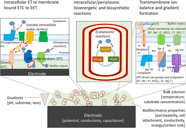
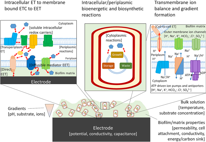
Possible components of a bioelectronic system that may contribute to the efficiency of EET. To the best of our knowledge, no model has taken into account all of these components, although they have been considered separately. The importance of each component varies, with some likely having little impact on the overall performance of the model. Electron-transfer reactions are shown by red arrows, ion translocation by blue arrows, and chemical reactions by black arrows. ET, electron transfer.

High-throughput microbial electrochemistry
Heterologous expression of non-native electron transport pathways in new chassis, or the redesign of these pathways or metabolisms in their native host, requires many iterations to optimize the desired functionality. Although not discussed above, the possibility for further optimization of engineered EET pathways through directed evolution will also require a parallelized culturing approach where cell growth is dependent on interactions with an electrode. High-throughput characterization and testing techniques must be developed to keep pace with the speed that EET pathway variants may be produced. In the case of engineered living conductive materials, the measured signal output is current from a complex protein system that enables electronic/ionic communication between living cells and a surface. High-throughput screening platforms to measure direct EET must take into account that: (i) the engineered organisms must be attached to a solid surface for the output to be detected, (ii) the output depends on the surface potential, and (iii) the biofilm system has significant mass transport limitations compared to a well-mixed batch reactor system (e.g. shaking culture flask) and may require continuous replenishment of medium. Expertise in microbiology, electrochemistry, and other fields, such as electronic engineering and microfluidics, will be required to develop new tools and adapt the existing tools to overcome these challenges.
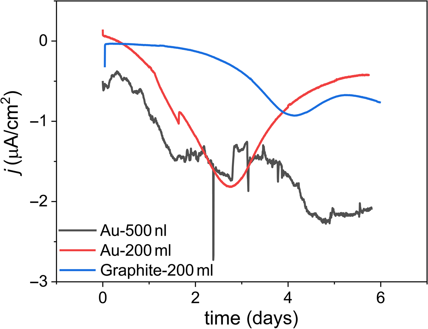
We propose that an electrochemical system for high-throughput microbial electrochemistry: (i) leverages microfluidic techniques to small test volumes in a continuous flow configuration, (ii) utilizes a three-electrode system to provide control over the surface potential of the electrode and a readout of the electrochemical response, (iii) incorporates sensitive electronic components to enable single- or few-cell measurements to decouple the need for cell growth from the testing of the engineered genetic circuit, and (iv) enables the capture of individual variants after testing. Some examples exist that incorporate (i) and (ii) above. High-throughput two-electrode microbial fuel cells were developed to increase the rate of isolation and enrichment of electrogenic organisms.[Reference Biffinger, Ribbens, Ringeisen, Pietron, Finkel and Nealson97, Reference Hou, Li, Ceylan, Haynes, Cope, Wilkinson, Erbay, de Figueiredo and Han98] These systems ranged from ~0.5 mL to 1.5 µL and were either operated in batch or continuous flow, but did not contain a built-in reference electrode for control over the electrode potential, which is required to precisely and quantitatively gate EET. In other studies, G. sulfurreducens was grown in a 0.3–24 µL flow cell chamber in either a two- or three-electrode configuration,[Reference Zarabadi, Charette and Greener99, Reference Yoon, Ahn and Schroder100] but only a single organism could be tested at a time in these setups. When microfluidics and nanoliter scale reaction volumes are used for microbial electrochemistry, initial electrochemical characterization on previously characterized strains, such as G. sulfurreducens, should be carried out to determine optimal flow rates and inoculation conditions before testing engineered strains. As a proof of concept, we replicated the current output of a biocathodic community (MCL)[Reference Yates, Strycharz-Glaven, Golden, Roy, Tsoi, Erickson, El-Naggar, Barton and Tender17] typically observed from 200 mL batch reactors in a continuous flow system that supports simultaneous testing of up to eight conductive biofilms in 0.5 µL chambers, each with a three-electrode system (Fig. 5). These initial results indicate that it is possible to scale down the size of the reaction volume 400,000× and still achieve a comparable biofilm output.
Comparison of representative chronoamperometry data from mL- and nL-scale electrochemical reactors with different electrode materials using the well-characterized Biocathode MCL as a model conductive biofilm. The nL-scale flow cell has a similar electrochemical profile to the larger reactors, indicating that testing engineered electroactive organisms at small volumes is a viable strategy for high-throughput characterization. All tests were run at 30 °C with artificial seawater as the electrolyte.[Reference Eddie, Wang, Malanoski, Hall, Oh, Heiner, Lin and Strycharz-Glaven9] The traces labeled Au-200 mL and Graphite-200 mL were operated in batch mode with a stir bar rotating at 200 rpm, while the Au-500 nL trace was operated in continuous flow mode at a flow rate of 40 µL/h. The working electrode potential of the batch reactors was set to 0.1 V versus Ag/AgCl, while the continuous flow reactor was set to −0.2 V versus Au quasi-reference electrode. The Au quasi-reference electrode potential was calibrated to the Ag/AgCl scale using a soluble redox shuttle, ferrocene methanol (E 0′ = 0.23 V versus Ag/AgCl in artificial seawater).
Throughput in the abovementioned devices could be dramatically improved if cells do not need to be grown for long periods of time before a detectable signal is produced. Improvements in the sensitivity of electrochemical instrumentation has enabled detection of electrochemical processes with a high femtoamp (fA) to low picoamp (pA) output.[Reference Wang, Noel, Velmurugan, Nogala, Mirkin, Lu, Guille Collignon, Lemaitre and Amatore101, Reference Batchelor-McAuley, Ellison, Tschulik, Hurst, Boldt and Compton102] Sensitivity in this current range should allow resolution of current output from single to tens of cells (~0.4 pA/cell; assuming a per cell output of electrons of ~2 × 10⁶ electrons/s/cell[Reference El-Naggar, Wanger, Leung, Yuzvinsky, Southam, Yang, Lau, Nealson and Gorby103]) instead of 106 cells in some cases,[Reference Yoon, Ahn and Schroder100] which should be detectable shortly after inoculation. Signal to noise can also be improved by the use of small electrodes where capacitive current will not obscure biologic signal at the electrode surface. Techniques which utilize signatures other than current output may also be leveraged for detection of EET at the single or few cell levels. For example, Raman[Reference Lebedev, Strycharz-Glaven and Tender15] and nano-Auger[Reference Avci, Davis, Wolfenden, Beech, Lucas and Paul104] spectroscopies have been used to characterize biotic/abiotic interactions, including redox gradients within electroactive cells and localized microbially-induced pitting corrosion processes, with sub-cellular resolution. Additionally, electrochemical surface plasmon resonance imaging, an extremely sensitive surface analysis technique with resolution limited by the number of pixels in the detector, has been correlated with current production from a G. sulfurreducens biofilm.[Reference Golden, Yates, Halsted and Tender105] If further developed into a high-throughput platform, such measurement could complement or replace three-electrode measurements. Ideally, any high-throughput platform will also enable cell-sorting for variant selection.[Reference Wang, Jones, Gralnick, Lin and Buie106]
Conclusion
The development of living conductive materials by leveraging the tools of synthetic biology and electromicrobiology is still in its infancy, and opens the door to improved applications for microbial EET, such as new catalytic coatings for electrodes of microbial fuel cells, as well as new applications in bioelectronics. Here, we have touched on the state of knowledge regarding natural living conductive biofilms and the challenges associated with designing and engineering them into functional living conductive materials. It is clear that a great deal of research and development remains before a living conductive material can approach the reliability and control currently available in conducting polymers. However, living organisms are capable of growth, self-repair, and a dizzying array of chemical reactions—in many cases with rates and specificities human chemists can only dream of. If we can harness these properties in organisms capable of wiring to electronic devices, this biologic–machine interface could have functionalities difficult or impossible to achieve with current technology—self healing coatings for machines and vehicles, sensitive and specific sensors that can report directly to a computer, and electronics that can “adapt”, in real time, to changing conditions.
Acknowledgments
We acknowledge Professor Chris Voigt (MIT) and Dr. Adam Meyer for providing both DAPG and IPTG sensors modified here for use in Marinobacter. This work was funded through the NRL Base 6.1 program and the Office of the Assistant Secretary of Defense for Research and Engineering Applied Research for the Advancement of S&T Priorities (ARAP) program, and Laboratory University Collaboration Initiative (LUCI).