

1. Background and design considerations
The Agile Sub-Ice Geological (ASIG) Drill system was developed in response to science goals identified in the Ice Drilling Program Office (IDPO) Long Range Science Plan 2013. Specifically recognized was a need to better understand the extent and volume of ice sheets under paleoclimatic conditions warmer than the present (e.g. Eemian) through the analysis of cosmogenic nuclides in the rock beneath ice sheets. A set of specific requirements was developed by the science community for the proposed drill system:
1.1. Science requirements
(1) Produce 700 m borehole to the base of ice with drilling and retrieval of 10 m of bedrock core and/or unconsolidated frozen sediment core.
(2) Ice drilling will include the possibility that the ice is entrained with rocks.
(3) Ice drilling will be to dry, frozen-bed conditions, and will not be done in areas where there is subglacial water.
(4) Retrieve several short ice cores (~50 cm long) at up to 700 m depth.
(5) Ice drilling may be in ice that is 2.0°C or more below the pressure melting point.
(6) Required ability to drill at ice borehole temperatures as low as −40°C, and surface temperatures as low as −30°C.
(7) Retrieve 10 m of bedrock cores of maximum 33 mm (1.3 in) diameter beneath the ice sheet.
(8) Maximum site altitude for the design should be 2500 m.
(9) Maximum time at a site, including set up and core retrieval, should be 6 d.
(10) Stand-alone capability is needed for operation at small field camps at remote sites.
(11) Minimal staff (4) for drilling operations in the field; other field camp staff in support of drilling operations to be provided separately.
(12) Drilling fluid or a fluid ‘system’ (to be determined) will be immiscible with water.
(13) Drilling fluid should not be a boron-rich fluid.
(14) Drill system must be transportable by Twin Otter, or helicopter with sling load.
(15) Drilling depth of each core collected should be determined and recorded.
(16) Drilling and core handling history should be recorded.
1.2. Cable-suspended drill option
An initial analysis of existing ice coring drills was conducted to determine whether any could be modified to meet the requirements for the ASIG Drill system. Traditional cable-suspended ice coring drills had been used for sampling beneath ice sheets and glaciers in several past projects but had only been able to collect limited quantities of subglacial material. The most successful of these efforts produced <5 m of subglacial material (Talalay, Reference Talalay2013). Success in true bedrock, especially in rock species of interest for cosmogenic analysis such as granite, was even more limited (Gow and Meese, Reference Gow and Meese1996). Drill systems beyond the size and scope envisioned for the ASIG Drill were necessary to obtain even these modest results. Additionally, the time-to-depth (TTD) for these conventional coring drills was far too high to meet the requirements set for the ASIG Drill system. It was therefore determined that a modified, traditional ice coring drill was unsuitable for the requirements of the ASIG Drill system.
1.3. Final concept
Rapid access to bedrock through an overlying ice sheet was explored in an Ice Drilling Design and Operations (IDDO, previous name of the US Ice Drilling Program or IDP) unpublished white paper in support of the development of the Rapid Access Ice Drill (RAID). A modified commercial minerals exploration drill rig was identified as best able to meet the requirements of such a project. A scaled-down version of the rig built and tested for RAID (Goodge and Severinghaus, Reference Goodge and Severinghaus2016) was determined to reliably meet all of the requirements for the proposed ASIG Drill system (Fig. 1).
ASIG Drill system concept model.
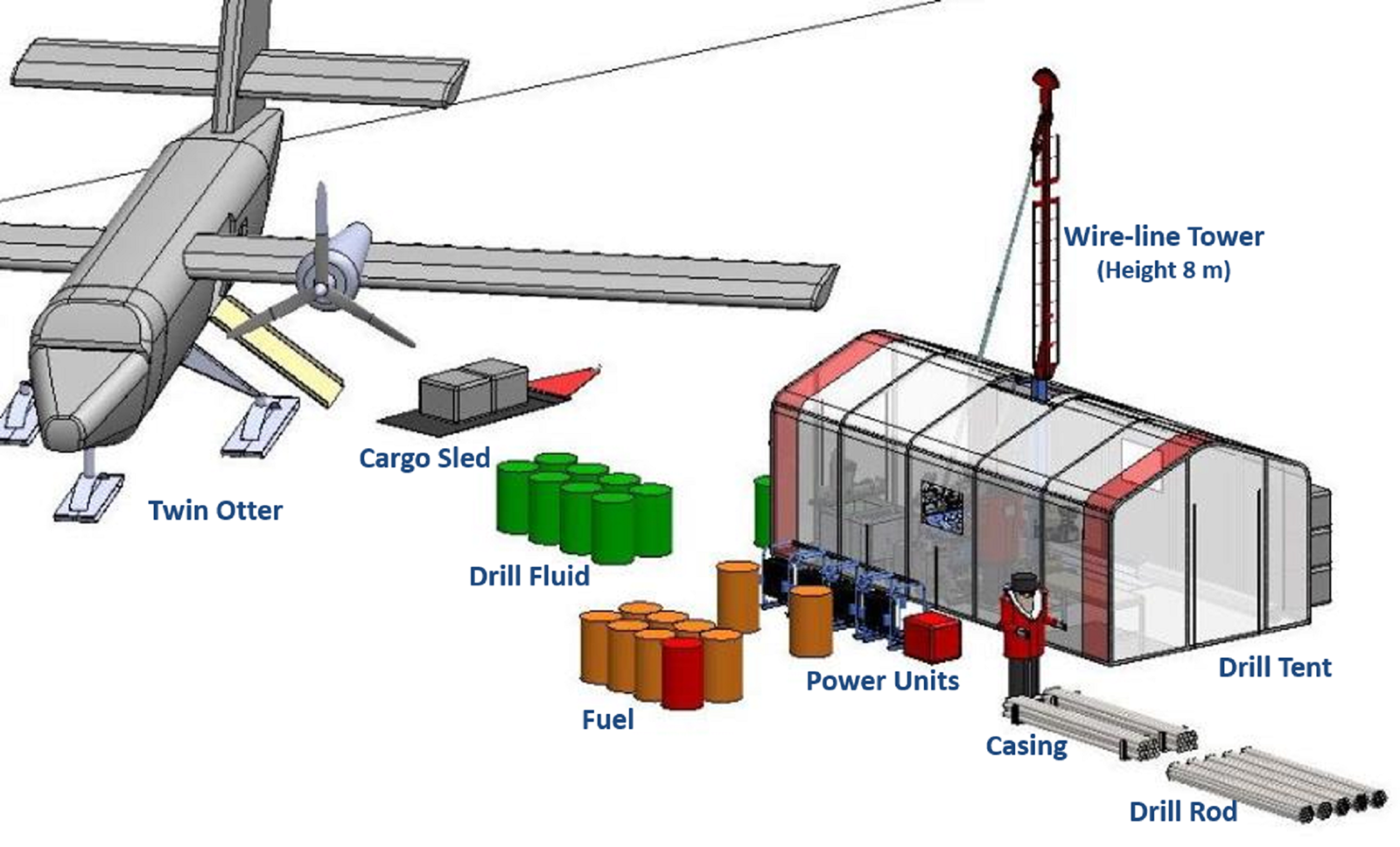
Minerals exploration drill rigs utilize a surface-driven, segmented pipe string tipped with a diamond-impregnated coring bit. Cuttings from the bit are carried to the surface via a circulating drill fluid. A filtration system removes cuttings from the drilling fluid as it circulates. Most modern rigs utilize wireline core retrieval, allowing cores to be recovered without pulling the entire string of drill pipe out of the hole.
2. Subsystems
The following subsections detail the features of the commercial drill rig that was procured and the modifications and additions completed to meet the ASIG Drill science requirements.
2.1. Drill rig
A thorough review of commercially available minerals exploration drill rigs (also known as diamond core drills) in the size range needed for the ASIG Drill was conducted. The rig ultimately procured was a customized version of the Discovery MP1000 Man Portable Diamond Core Drill built by Multi-Power Products Ltd. of Kelowna, British Columbia, Canada. The rig features a lightweight, modular design that allows for transport and assembly at remote field sites without the use of heavy equipment (i.e. forklift, crane, etc.). Individual components were sized to be transportable via De Havilland DHC-6 Twin Otter aircraft commonly used for remote site access in polar regions.
The drill rig consists of eight primary modules (Fig. 2): mast module with top drive, footclamp and wireline winch/tower; control module; hydraulic tank module with oil cooler; four diesel engine modules driving individual hydraulic pumps; and a diesel fuel bulk tank. The customized version of the drill rig built for the ASIG Drill was reengineered by Multi-Power to use aluminum in place of steel wherever possible to reduce weight. The modules are assembled and interconnected with hydraulic/fuel hoses and electrical/throttle cables at the drill site. Modules located outside the drilling tent are fitted with vinyl-coated polyester fabric enclosures to prevent snow infiltration and reduce pre-warming time in cold temperatures. Specifics of the final drill rig are given in Table 1.
ASIG Drill rig during initial acceptance testing in Madison, Wisconsin, USA in 2015.

Multi-Power Man Portable Drill Rig model MPP-001-7484 specifications (customized for ASIG Drill system)
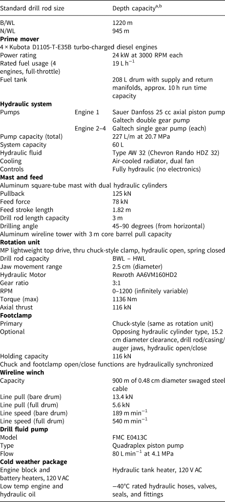
a Depth capacity may be increased with the use of thin-kerf or other lightweight drill rods.
b Based on maximum rig pullback with 25% safety factor.
A load-spreading footing of aluminum I-beams, polyethylene sheeting and aluminum perforated planking was designed to interface with the standard rig base. The footing reduces the snow pressure of the operating drill rig to a maximum of 0.2 kg cm−2.
A variety of electronic sensors were added to the standard rig by IDP. These include feed rate and payout of the top drive via a linear encoder, RPM via a proximity sensor on the rotation unit and winch payout via a rotary encoder on the wireline tower crown sheave. Sensors are output on four LCD displays added to the operator's console.
2.2. Pilot hole auger/corer
Most potential ASIG Drill sites are covered with permeable snow and firn. A larger-diameter pilot hole must be created through these permeable layers into impermeable ice so that a sealed casing can be installed. The drill rig is used to drive continuous-flight augers or a corer assembly to create a 146 mm diameter hole. Blue ice sites require a short pilot hole to get below any surface cracking and allow for sealing to un-cracked ice. Exposed rock can be cored without a pilot hole in most situations.
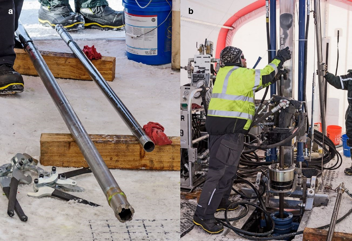
Solid-stem, continuous-flight augers have successfully been used to drill the pilot hole for the ASIG Drill (Fig. 3a). Augers provide fast TTD but cannot recover samples for density analysis. Hollow-stem augers can also be used to create the pilot hole. The stem of these augers is made from pipe, rather than a solid rod. Wireline-deployed tooling can be run through the center bore, allowing the exchange of a center bit and sampling tube for ice sample retrieval (for density verification). A significant quantity of cuttings is left in the hole following augering, anywhere from 2 to 30% of the hole depth, depending on multiple factors. Other downsides of augers are their tendency to increase the borehole diameter in soft formations and the increased probability of micro-cracking of the borehole wall (which can contribute to hydraulic fracturing) from the aggressive cutting action.
(a) Pilot hole creation with solid-stem continuous-flight augers. (b) An ice corer barrel used to remove cuttings and/or deepen the pilot hole. Coring barrels can retrieve samples of the firn for use in density verification before setting the packer.
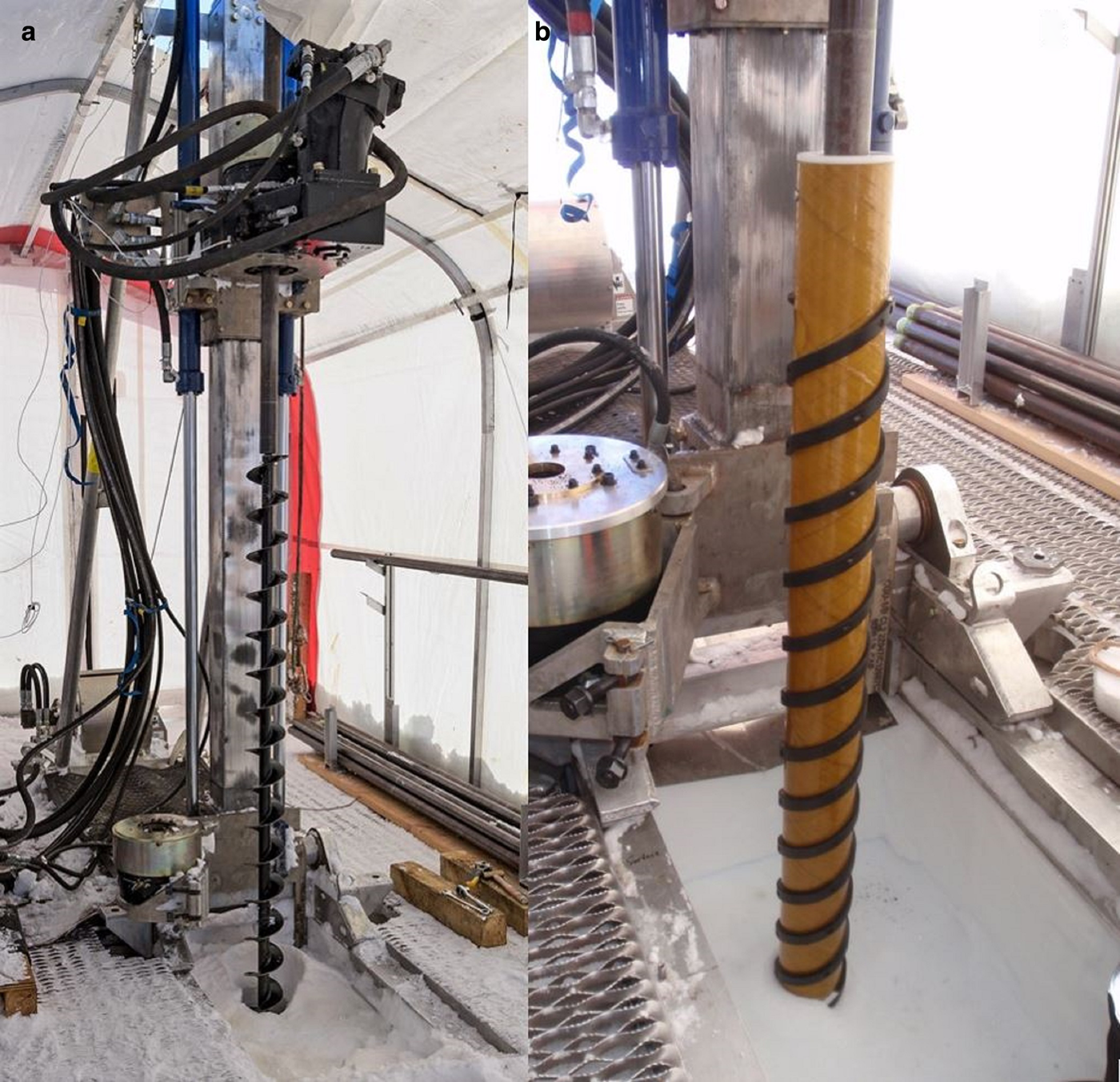
Several existing corer assemblies can be used to drill the pilot hole. The corer assembly is driven by standard drill pipe in a conventional manner (i.e. cores and cuttings are recovered by removing the entire drill string). Coring the pilot hole is relatively slow (compared to augers) but has the advantage of collecting samples for density analysis to confirm when impermeable ice has been reached (Fig. 3b). Also, the corer assembly leaves almost no chips in the bottom of the hole and creates a better borehole wall surface finish for the packer.
Cuttings remaining from augering can cause problems during subsequent drilling operations. A corer assembly can be used to remove cuttings from the bottom of the augered hole, but is inefficient due to the amount of time needed to trip drill pipe in and out of the hole. A stand-alone, wireline-deployed, electromechanical chips bailer/corer was developed for use with the ASIG Drill from the existing IDP 4-Inch Drill to speed operations. The bailer attachment collects cuttings with a continuous-flight auger section rotating inside a splined outer barrel. A traditional two-barrel corer assembly can also be used in place of the bailer assembly on the same motor/anti-torque section and cable to collect ice samples for density verification and deepen the borehole to improve borehole wall surface finish for the packer to seal against.
2.3. Casing, packer and diverter
A conduit between impermeable ice and the surface is needed for the drill to operate. Three-meter sections of 76.2 mm outer/66.6 mm inner diameter aluminum tubing with fluid-tight threaded joints are used to form the casing connecting the packer at the bottom of the pilot hole to the diverter just above the surface. A bow-type centralizer is attached to each section of the casing to prevent the casing from deflecting excessively in the large pilot hole diameter necessary for the packer.
An inflatable packer commonly used in the oil and gas industry terminates the casing string downhole. The packer consists of a central pipe surrounded by an inflatable rubber element (Fig. 4a). Fittings at the top of the packer allow connection of nylon inflation/deflation line(s) that are run alongside the casing to the surface. The packer can be inflated with compressed gas (nitrogen or ambient air) or a liquid, such as Isopar K. Liquid inflation requires the use of separate supply and return tubes so that compressed air can be used to purge liquid from the packer (against hydrostatic pressure), allowing the packer to deflate before removal. Common liquid-inflation pressure is ~1.38 MPa, while for gas-inflation, a pressure of ~1.10 MPa has been used (limited by compressor capacity, but adequate to achieve a seal).
(a) Inflatable packer installation. (b) Diverter and sump pit liner installation.
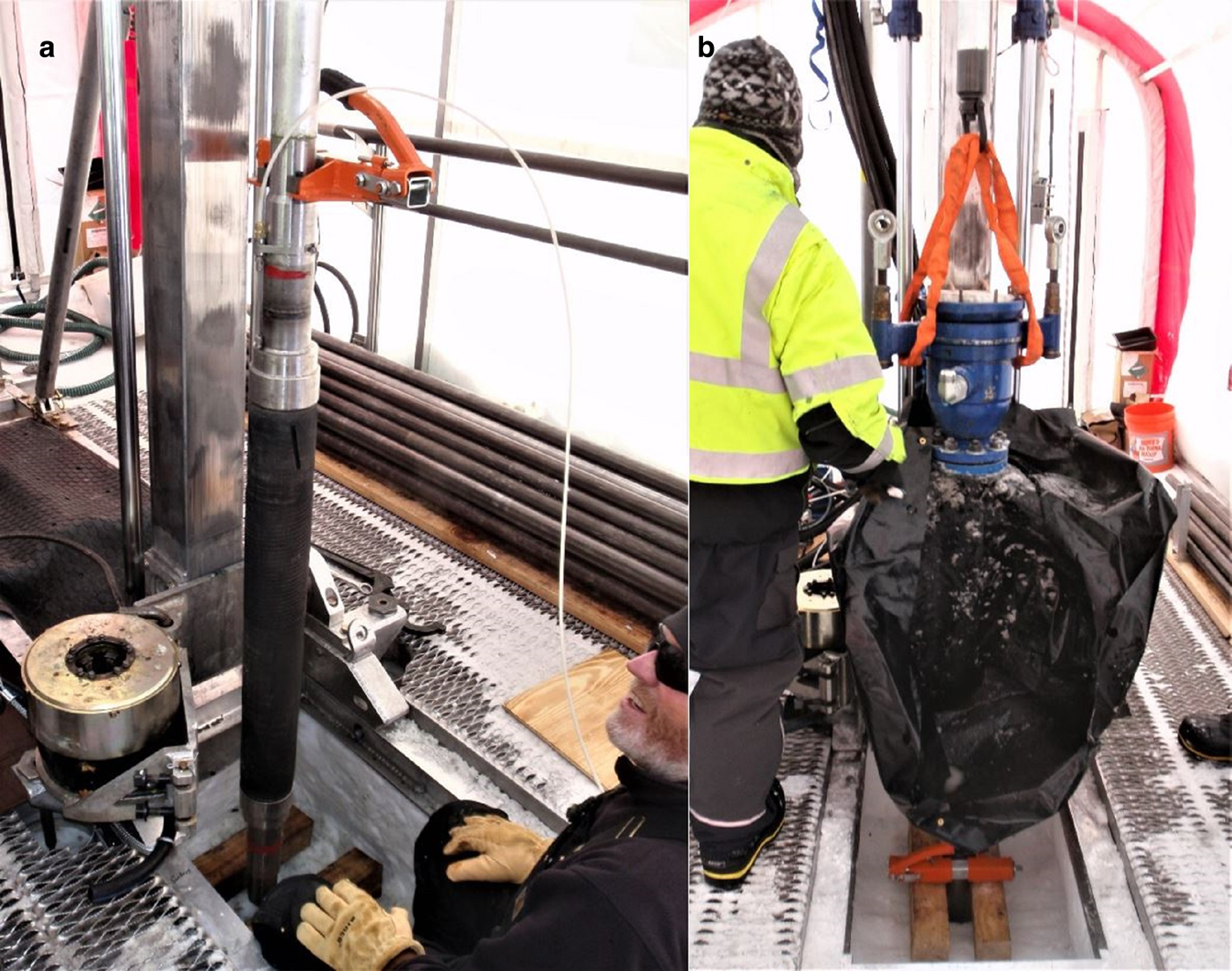
The diverter is another commonly used oil and gas industry device that provides a sealed feed-through for the drill pipe to enter the casing filled with pressurized drilling fluid. It is composed of an outer metal body that connects to the casing on the bottom and to a hose running to/from the drilling fluid circulation manifold (Fig. 4b). An elastomeric stripping-rubber seals between the drill rod and the diverter body. Drilling fluid can flow in either direction through the diverter. The system can be configured to operate in normal (forward) or reverse circulation (see Section 2.5). The diverter is necessary to operate in reverse circulation, while normal circulation can also be accomplished by use of a sump pit/pump.
2.4. Downhole tooling
Sandvik WL56 thin-kerf drill pipe and TK56 wireline coring components were selected for use with the ASIG Drill rig. The WL56 drill pipe has 53.2 mm outer diameter, 46.0 mm inner diameter and weighs 11.3 kg 3 m−1 pipe section (compared to 18.0 kg for standard B-size pipe).
A non-coring (or ‘full face’) bottom hole assembly (BHA) is used to create the access hole from the bottom of the pilot hole to the depth at which core samples are desired. The ASIG Drill uses an IDP-designed full face bit with 62.5 mm diameter to create the access hole (Fig. 5a). The bit features three A2 tool steel cutters with R58c cryogenic heat treatment for durability, each with a rake angle of 30° and clearance angle of 15°. A rate of penetration (ROP) of up to 2 m min−1 at 200 RPM is possible with this bit geometry. Two custom ice reaming shells, or centralizers, with zero borehole clearance, are placed on the BHA, one behind the bit and one between the TK56 Outer Tube and the bottommost drill pipe, to stabilize the drill string at the bit. The access hole BHA components are designed to be used while reverse-circulating drilling fluid in order to keep ice cuttings within the drill string. Normal circulation is possible as well but with the increased risk of clogging in the tight annular space around the drill pipe.
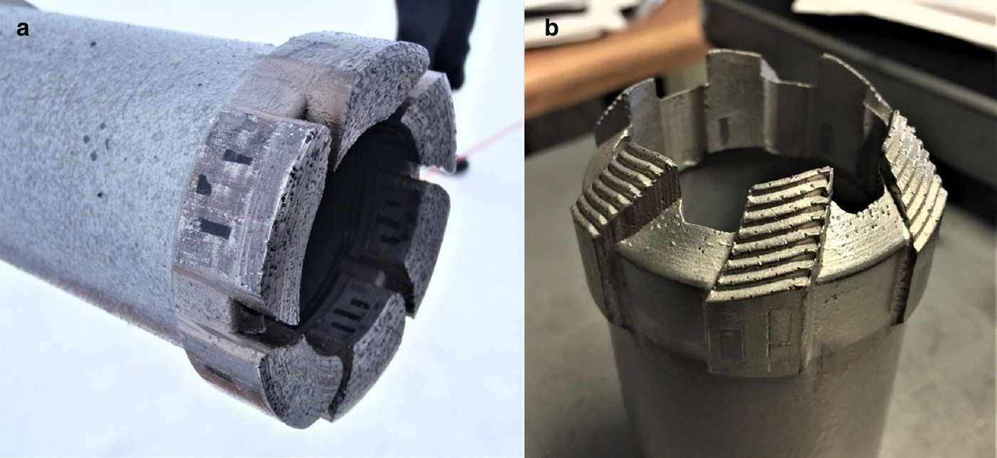
(a) Full face ice bit and lower reaming shell for drilling the access hole. (b) PDC coring bit for ice and rock.

An ice coring bit can be used in place of the full face access bit described above. This requires pulling the drill string to swap the bit. All ASIG Drill ice coring bits create a 39.0 mm core and maintain the 62.5 mm borehole diameter of the access hole. Three ice coring bit types have been developed for the drill system: polycrystalline diamond compact (PDC), thermally stable polycrystalline (TSP) geoset and diamond-impregnated. All bit types are designed for use in mixed formations (ice with entrained rock, sand, etc.) as well. The PDC coring bits feature six 1308-grade disc cutters (8 mm diameter, 1.5 mm thick) with 20° back-rake (negative rake angle) and 20° clearance angle (Fig. 5b). Geoset bits feature small TSP-type diamond elements set in a wear-resistant matrix. The custom diamond-impregnated (i.e. ‘hybrid’) bits built for ASIG have a toothed cutter geometry cast into the matrix. PDC-type coring bits have performed best of the designs used so far. Geoset bits have worked moderately well but tend to produce more melting. The toothed hybrid coring bits have been unsuccessful due to excessively high pump pressure, likely because of clogged waterways in the bit face. A traditional coring bit for ice (positive rake, hardened tool steel cutters) could be used with ASIG to maximize ice core quality but has not yet been designed. All coring bits are designed for use with normal fluid circulation.
A variety of custom drill bits for rock have been designed for use with the ASIG Drill, both full face and coring. Full face rock bits are designed for drilling through unconsolidated or highly fractured formations where the core is not desired or is difficult to collect. Full face and coring rock bits are available in PDC, geoset, standard diamond-impregnated (Fig. 6a) and toothed hybrid geometry (Fig. 6b). Good quality rock core (granite) has been recovered with PDC and diamond-impregnated coring bits. The full face rock bits have not been used extensively yet. Coring bits are designed for use with normal fluid circulation, while full face rock bits can be used with normal or reverse circulation (although normal circulation is standard).
(a) Worn diamond-impregnated coring bit for rock. (b) Hybrid diamond-impregnated coring bit, designed to core through the ice-rock transition, have been mostly unsuccessful due to the excessive pump pressure required.
Reaming shells to stabilize the BHA and gauge the borehole while rock drilling/coring are included with the ASIG Drill system. They are used in pairs, one directly behind the bit and one between the outer core barrel and the first drill pipe. The outer surface of the reamers includes diamond-impregnated surfaces with zero borehole clearance separated by waterways for drilling fluid circulation.
The TK56 wireline coring tools allow a core barrel assembly to be alternately latched and unlatched into the BHA to recover ice and rock core to the surface without having to pull the entire drill string every run (Fig. 7a). The core barrel assembly is pumped down with normal circulating drill fluid to the BHA, where it automatically latches into the outer core barrel (Fig. 7b). An optional dry-hole lowering device can be used to trip the inner core barrel assembly to the bottom using the wireline winch. The bottom of the inner core barrel, which sits directly behind the coring bit face when latched into the outer core barrel, contains a split-ring tapered core lifter that grips the core (ice and rock) when the drill string is lifted slightly during core break and retains the core in the inner core barrel. The wireline winch is used in conjunction with an overshot to connect to the core barrel head assembly at the top of the inner core barrel, unlatch the head assembly from the outer core barrel and pull the core barrel assembly to the surface. Core barrels are available for 1.5 and 3 m core lengths.
(a) BHA with coring bit and rock reaming shell (left) and inner core barrel assembly (right). (b) Deploying the inner core barrel assembly into the drill pipe string.
Several fishing tools are available to help retrieve broken tooling from the borehole. Tapered recovery taps with sharp, right-hand threads are available for both drill pipe and casing. They are run downhole on drill pipe and rotated to thread into the top of broken or dropped pipe/casing for retrieval. An expanding recovery tap can also be used for recovering drill pipe without rotation. A casing cutter is included with ASIG for cutting off stuck casing that cannot be otherwise retrieved. It is run downhole on drill pipe and features a milling cutter that expands with hydraulic pressure from the drilling fluid. For recovering broken wireline downhole, both internal- and external-toothed spears can be run downhole on a drill pipe or with the winch. Magnets of both borehole and drill pipe inner diameter are included for recovering ferrous metal parts from the borehole via drill pipe or wireline winch.
Drilling fluid can be removed from a borehole with a swab assembly or with a bailer. The swab assembly runs on the wireline winch inside the drill pipe string. Swab cups with tight clearance to the drill pipe bore slide on a mandrel, alternately sealing to pull fluid from the hole on the up stroke and releasing to allow fluid to bypass on the down stroke so that the swab assembly can be tripped to the bottom of the drill string. Swabbing fluid from the borehole is very efficient initially, but loses effectiveness as the empty portion of the borehole increases due to unavoidable fluid bypass in the swab mechanism. A completely empty borehole is not achievable with a swab alone. The fluid bailer assembly consists of a section of drill pipe (up to 6 m long) with a one-way valve attached to the bottom. The bailer is run up and down the borehole with the wireline winch, removing ~10 L of drilling fluid per run. A completely empty borehole is achievable, barring borehole closure from unbalanced hydrostatic pressure. Fluid brought to the surface via either method is collected and filtered for reuse.
2.5. Drill fluid circulation and cuttings filtration
Circulating drilling fluid is essential to ASIG Drill operation in order to cool and clear the bit of ice cuttings, to transport cuttings out of the borehole, and to pressure balance the hydrostatic force on the borehole from the surrounding ice. A variety of hydrophobic liquids of sufficiently low freezing point and material compatibility are suitable for use with the ASIG Drill. Liquids of various viscosity and density can be used, with corresponding benefits and trade-offs for pumping pressure, necessary flow velocity to lift cuttings, amount of borehole pressure-compensation, etc. Currently, the ASIG Drill is configured to use Exxon Mobil Isopar K, a low-VOC naphtha isoparaffin fluid. Isopar K has a boiling point of 183°C, flash point of 58°C, aromatic content of 0.01 wt%, density of 0.762 g mL−1 at 15.6°C, vapor pressure of 0.05 kPa at 20°C and kinematic viscosity of 1.58 mm2 s−1 at 25°C. Drilling fluid is generally transported in 200 L drums and supplied to the drill system bulk tank with the aid of a 12 volt DC electric drum pump. Large projects with tractor traverse support can utilize drilling fluid in 1000 L totes or 10 000-plus liter flexible bladders.
A hydraulically-driven piston pump common to the minerals exploration industry (see Table 1) pumps drilling fluid from a bulk tank to a custom-built manifold of manual valves that can be used to supply fluid to the borehole in normal or reverse circulation direction (Fig. 8a). An adjustable pressure relief valve on the pump outlet bypasses fluid above a set-point to prevent over-pressurization of the ice formation (Fig. 8b).
(a) Driller's control console, with drilling fluid manifold and rig sensor displays mounted on top. (b) Quadraplex piston pump for drilling fluid circulation, with pressure relief valve shown in the upper right.

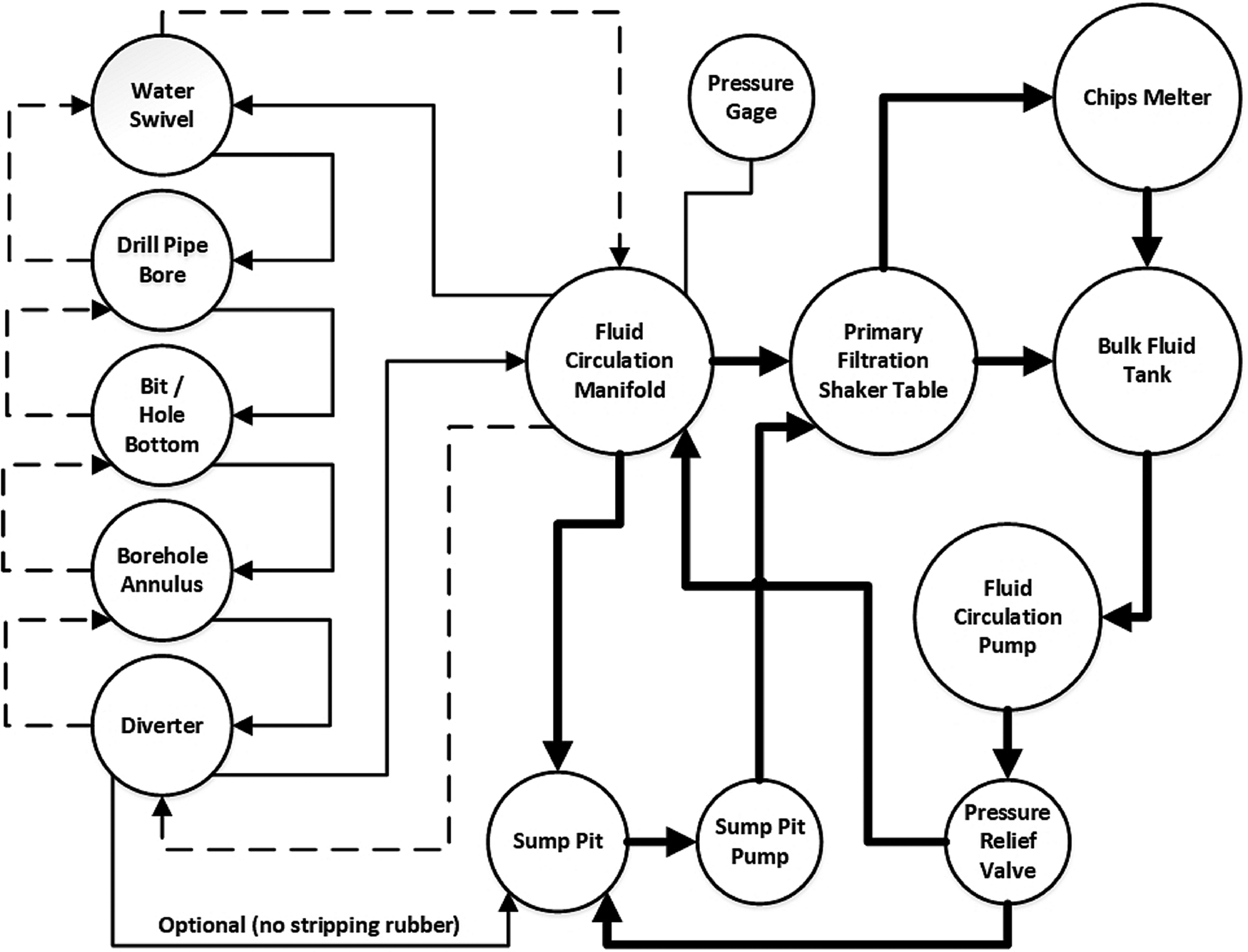
When the manifold is in the normal circulation configuration, drilling fluid is pumped to the bit down the bore of the drill pipe string and returns to the surface in the annular space. Reverse circulation, where supply fluid from the pump flows downhole in the annular space and returns to the surface within the drill string, is set by actuating two three-way valves on the manifold. An additional valve on the manifold allows fluid to bypass the borehole entirely to quickly remove pressure from the system. This circuit can also be used to quickly fill a partially empty drill pipe string before redeploying the inner core barrel assembly downhole (Fig. 9).
Drilling fluid circulation overview diagram for the ASIG Drill system. Thin solid lines indicate fluid flow in normal circulation, dashed lines indicate reverse circulation, and bold solid lines indicate fluid flow direction that is common for both.
A rotary coupling called a water swivel is used to connect the drilling fluid circuit to the rotating drill string. It threads to the uppermost drill pipe and routes fluid between the drill string and the manifold. Separate water swivels and hoses are used for normal and reverse circulation to account for the different pressure and cuttings concentration inherent in each drilling mode. The diverter assembly on top of the casing provides the other rotary seal to the drill string and routes fluid between the borehole and the manifold in both flow directions.
Drill fluid returning from the borehole, in both normal and reverse circulation, flows back through the manifold to the primary filtration system located on top of the bulk tank. The initial version of the filtration system featured a combination of wedge-wire filter screen, continuous-flow screw press and 100 μ filter bags to remove most of the drilling fluid from the ice cuttings. The system was prone to clogging and unable to continuously process the necessary fluid/cuttings volume during normal drilling operations. An upgraded primary filtration system was subsequently designed and built for the ASIG Drill that uses a hydraulically-driven shaker table with mesh screens of various micron rating (Fig. 10a). An additional 600 μ strainer is installed inline from the fluid outlet of the shaker table to the bulk tank. The upgraded primary filtration system has undergone limited testing but has not yet been used for production drilling with the ASIG Drill.
(a) Shaker table filtration system undergoing testing to separate ice cuttings from drilling fluid. (b) Chips melter tank in use at Pirrit Hills, Antarctica.

The ice cuttings slurry from the primary filtration system contains a significant quantity of drilling fluid that can be recovered in a melter tank included with the drill system (Fig. 10b). Waste heat from Engine 1 is utilized to melt the cuttings by routing warm engine coolant through a length of copper tubing in the bottom of an insulated tank. The cuttings slurry is added to the melter tank in batches. The melter system can heat a 30/70% ice/fluid slurry from −20 to 0°C in ~15 min. Ball valves located in the tank wall at slightly different heights allow water, which is denser than the drilling fluid, to be drawn off with the lower valve, while drilling fluid can be recovered from the upper valve. A small amount of fluid remains in the tank to assist in melting the next batch. Drilling fluid from the melter is warm and must be cooled ambiently, or with a fan-forced radiator and pump assembly, before it can be added back into the bulk tank. Nearly 100% of the drilling fluid in the cuttings can be recovered with the melter system, excepting some evaporation and spills.
Additional equipment for drilling fluid containment and handling is included with the drill system. A sump pit with a flexible liner is located at the top of borehole (surrounding the diverter) to contain drilling fluid lost during routine operations. A debris-tolerant drum pump can be energized to move fluid from the sump pit to the filtration system. The sump pit and pump can also facilitate normal circulation drilling without the diverter stripping rubber installed, if needed. A container known as a ‘slobber pot’ seals to the top of the drill pipe string when pulling the overshot/inner core barrel and fluid bailing swab assembly to catch the drilling fluid coming from the drill string and route it to the filtration system via the sump pump. An additional fluid containment device for a ‘wet trip’, pulling a drill string full of fluid due to a clog somewhere in the pipe string, utilizes wiper seals on both sides of a cylindrical housing so that the pipe joint can be separated within the sealed cavity without spraying drill fluid on the operators. A hose from the housing drains drilling fluid to the sump pit.
2.6. Shelter
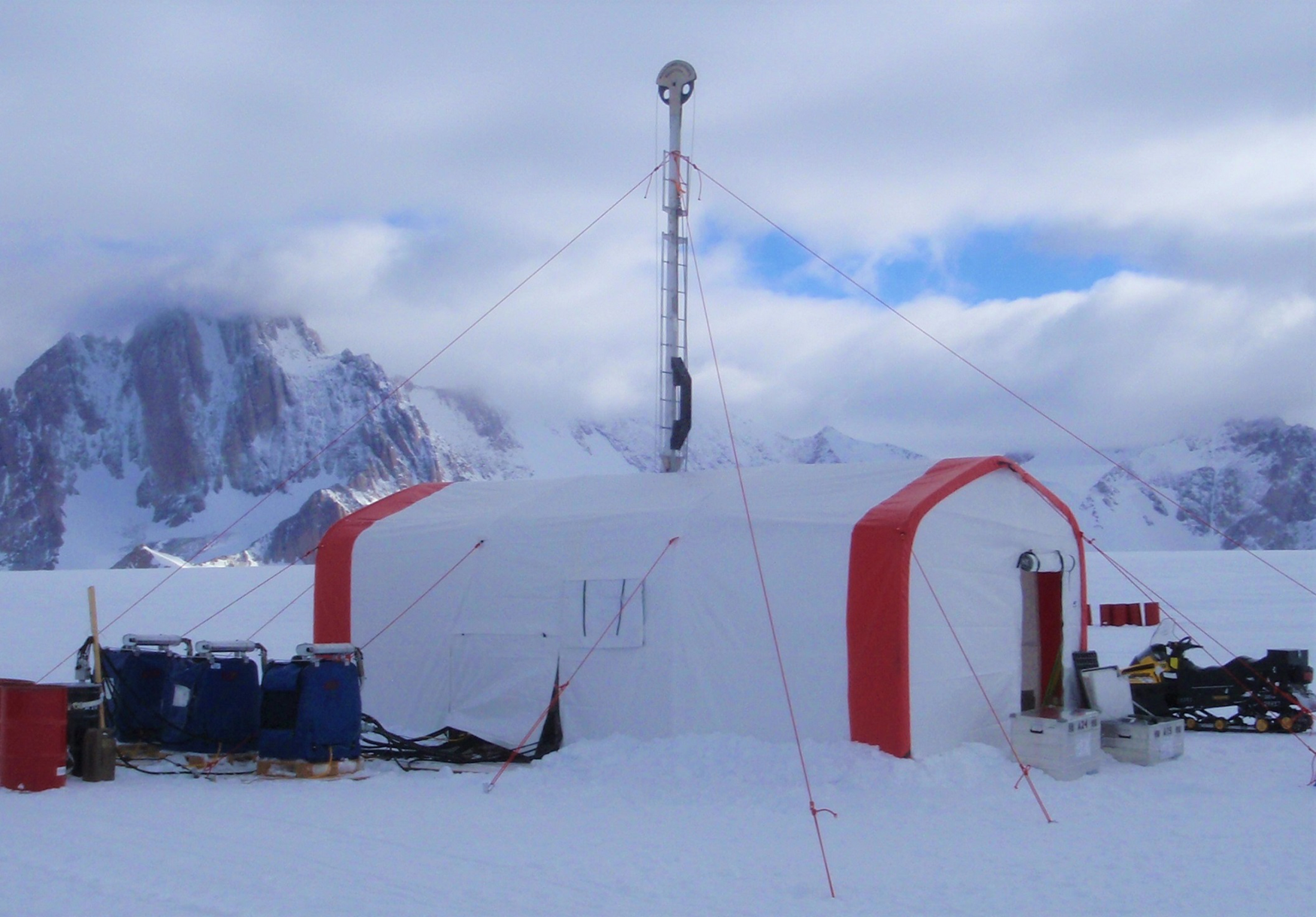
A custom tent was designed and built for the ASIG Drill system by WeatherPort Shelter Systems of Delta, Colorado, USA (Fig. 11). The 3.66 × 7.62 × 3.05 (width × length × peak height) meter tent consists of cable-tensioned fabric over a tubular aluminum frame. A valence runs along the entire perimeter to anchor the tent with piled snow. Guylines and pickets are used for additional anchoring. Zippered doors are located at each end of the tent, with openable vinyl windows in the sidewalls. Access panels in the roof and one sidewall provide openings for the rig mast/wireline tower and hydraulic hoses, respectively. The structure is rated to withstand −50°C temperature and 32 m s−1 sustained winds with 38 m s−1 gusts. Shipping weight is ~365 kg.
ASIG Drill tent in use at Pirrit Hills, Antarctica in 2017.
3. Operations
3.1. Logistics and shipping
The ASIG Drill system is designed to deploy to remote field sites in polar and other glaciated regions via a variety of means (Fig. 12a). All modules can be packaged to fit within the maximum cargo dimensions of the DHC-6 Twin Otter, or larger, aircraft. Helicopter transport is also feasible, generally with external loads. Many flights are required for small fixed and rotary-wing aircraft to transport the entire system, with the exact number of flights depending upon multiple factors. Large cargo aircraft, such as the LC-130 Hercules, can field the entire system in as few as one flight. The system is particularly well-suited to field transport via over-snow tractor traverse (Fig. 12b). Table 2 details the system component weights and transport details.
(a) Palletized ASIG Drill cargo at McMurdo Station, Antarctica. (b) ASIG Drill cargo on traverse sleds after completing the 2016–17 field season at Pirrit Hills, Antarctica.

ASIG Drill system weights and logistics for shallow and deep projectsa
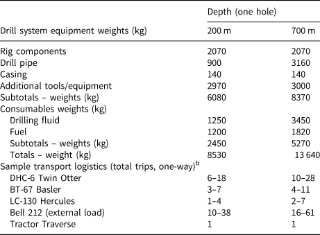
a Sample projects. Weights are highly dependent upon exact project requirements.
b Depending on distance, elevation, fuel availability and skiway condition (fixed-wing).
3.2. Drill system assembly
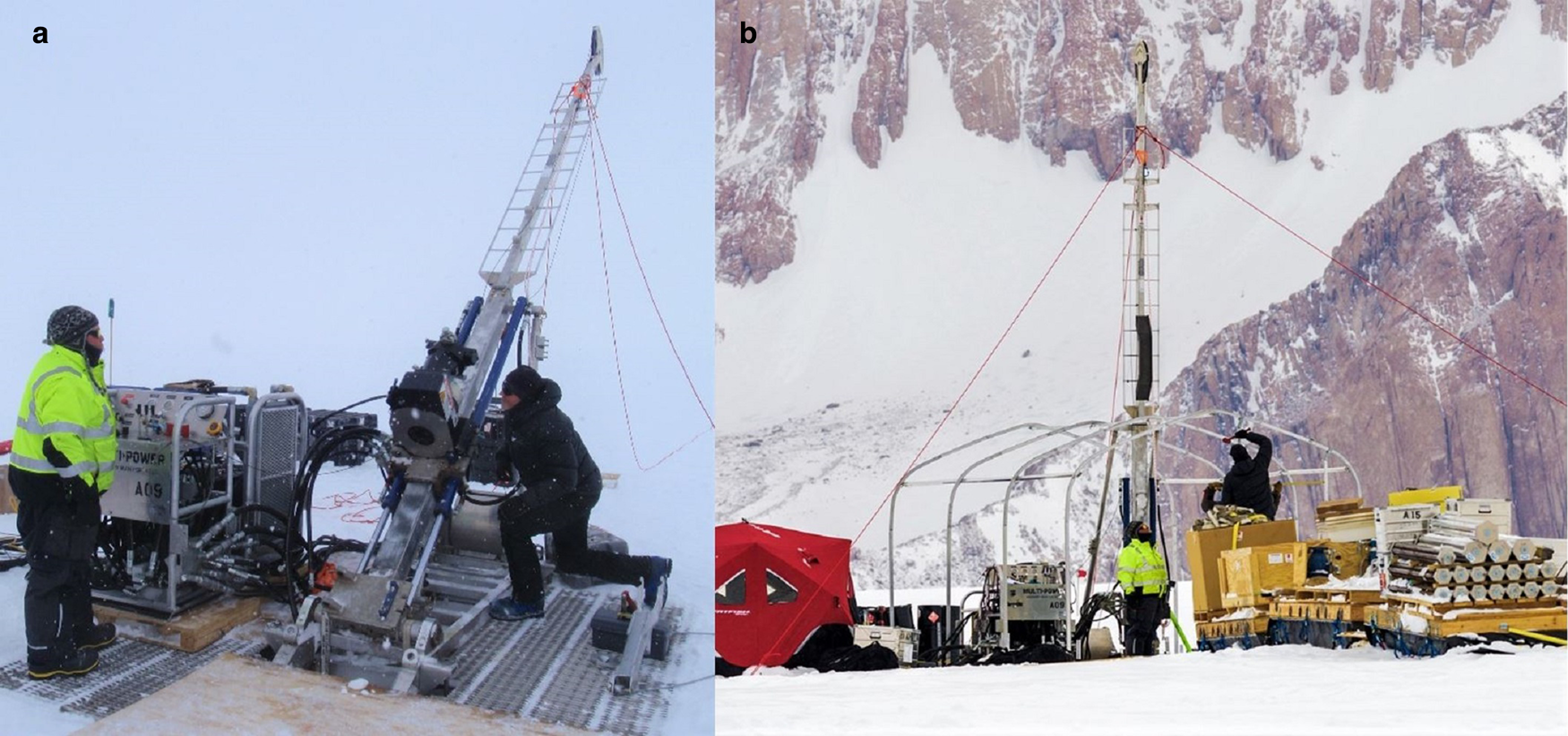
Drill system assembly in the field is best accomplished with four or more people, although the system can be assembled with as few as two people with heavy equipment support. Initial unpacking and total system construction has taken ~30 h previously, but this time depends heavily upon site conditions, the availability of support equipment for site preparation and cargo handling, and the degree of operator experience with the drill system. A level pad for the drill rig footing and shelter is required. Large drill modules such as the footing and rig base, mast, control, hydraulics and filtration modules are moved into place initially, and then the tent is assembled around them to protect the system from the weather while subsequent interconnection of components is done. The drill mast and wireline tower are raised to vertical with the aid of the hydraulic feed cylinders. Complete disassembly and packing of the drill system requires ~20 h. Disassembly to move between relatively close sites may take significantly less time. Figure 13 shows drill system construction at the Pirrit Hills, Antarctica during the 2016–17 field season.
(a) Initial drill set-up involves setting the footing, rig base/mast/wireline tower and hydraulic control system. (b) The drill tent frame being assembled around the drill mast/tower at Pirrit Hills, Antarctica.
3.3. Drill system performance
Table 3 gives performance values for the ASIG Drill system, as demonstrated over various tests and a field season of operations with the drill.
ASIG Drill system operational performance values
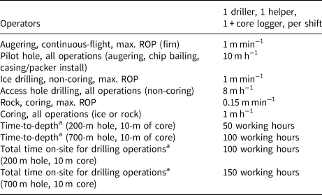
a Estimated (system at maximum efficiency). Deep firn, difficult formations, mechanical issues, weather, operator experience, etc. can significantly alter performance estimates.
4. Field tests
Several separate field tests were conducted during the development of the ASIG Drill. In February of 2016, packer and hydraulic fracture testing was conducted outside of McMurdo Station, Antarctica. The tests confirmed that the inflatable packer could reliably seal to an ice borehole wall with either compressed gas or liquid inflation media at 700–2800 MPa (at pump outlet). Fracturing of the ice due to the pressure exerted by the packer itself was shown to be unlikely to occur. However, hydraulic fracturing of the ice below the packer by pressurized drilling fluid was shown to be a concern (see Section 7). Tests indicated hydraulic fracturing could occur with as little as 690 kPa borehole pressure (measured with a downhole pressure transducer below the packer), although the warm, shallow and stressed ice at the test site was thought to be weaker than future ASIG drilling sites. Pilot hole creation with a continuous-flight auger was also tested and shown to be feasible. Several anchoring schemes for the drill rig were tested during separate fieldwork at the South Pole, Antarctica in January of 2016.
A drill system test was completed at an ice well facility at the Physical Sciences Lab of the University of Wisconsin-Madison during February and March of 2016 (Fig. 14a). A steel casing of 25.4 cm inner diameter and 15 m length was filled with water in increments and frozen over several weeks by circulating chilled glycol (from a refrigeration unit on the surface) around the casing. The bottom 1.8 m of the casing contained a granite block secured with concrete for rock coring tests. The test served as the initial commissioning of the drill rig with a mechanic from the manufacturer onsite. Access hole drilling (non-coring) in clean ice was tested, in both normal and reverse circulation, with different cutter geometries. Ice and rock coring was tested with a variety of bit types. Drilling fluid flow rates and pump pressures were characterized for various drilling configurations. The drilling fluid filtration system was tested for throughput and filtration efficiency. Several IDP personnel were familiarized with rig operations for future involvement in field projects.
(a) ASIG Drill rig during initial system commissioning outside Madison, WI, USA in 2016. (b) Transition core from ice to rock (concrete) during ASIG Drill system testing in 2016.

The test demonstrated the basic functionality of the ASIG Drill system and indicated the drill was likely to satisfy the science requirements established for field projects (Fig. 14b). A variety of system deficiencies were also identified that were able to be addressed prior to the first field use later that same year at the Pirrit Hills, Antarctica.
5. Pirrit Hills, Antarctica field season
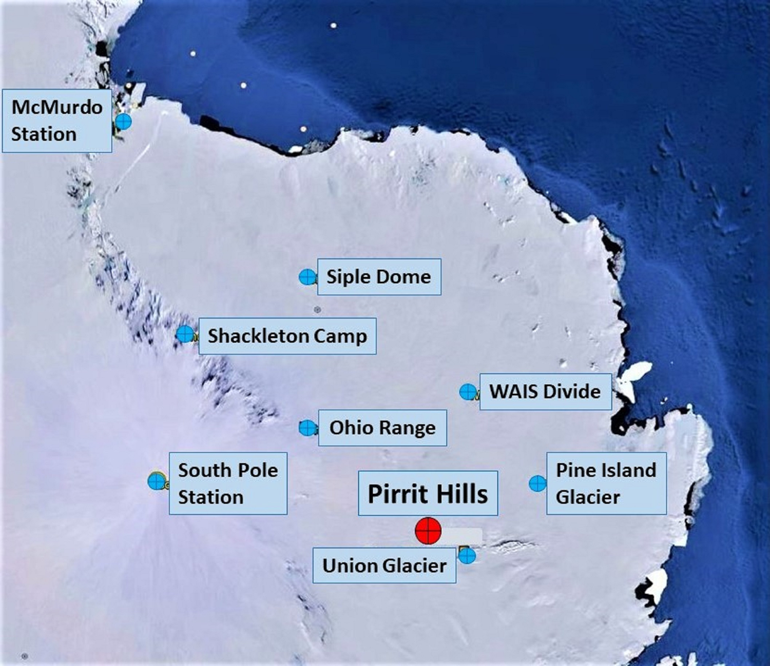
This project was the initial field use of the ASIG Drill system and was conducted from October through January of 2016–17. Project goals were to drill two holes, ~100 and 200 m deep, respectively, retrieving 10 m of ice and 5 m of rock core from the bottom of each hole (Spector and others, Reference Spector2018). Transport to the field site in western Antarctica was accomplished by LC-130 Hercules aircraft from McMurdo Station to WAIS Divide field camp (two flights) and by over-snow tractor traverse from WAIS Divide to the Pirrit Hills site (7 d, Fig. 15). Resupplies and personnel movement were also facilitated with DHC-6 Twin Otter aircraft support out of WAIS Divide. The project was hampered by long logistical delays, with only about a third of the total project days available for drill operations. Three IDP personnel deployed with the project: an experienced driller from the minerals exploration industry, a drill helper and a project lead/engineer. Three science personnel from the University of Washington directed the project, led by Dr John Stone. The US Antarctic Support Contractor supplied the traverse operations and camp support personnel and equipment. All field operations were accomplished with single-shift operations.
The Pirrit Hills is an isolated area of exposed rock located in western Antarctica, near the Union Glacier blue ice area.
Drill system construction at Site 1 (100 m estimated ice depth) began on 16 December 2016 and required 4 d to complete. Pilot hole drilling was accomplished with a corer assembly run on drill pipe in a conventional manner, which proved highly inefficient due to drill rod tripping time and poor corer performance (clogging). The casing and packer were initially set on 23 December 2016 at a depth of 26 m in the ice of 810 kg m−3 density. An attempt at access hole drilling with reverse-circulating drilling fluid was immediately unsuccessful, as the ice surrounding the packer was not sufficiently dense to prevent fluid leakage. The casing/packer string was pulled and the pilot hole deepened to ~37 m deep with the corer assembly, with the packer then sealed to the ice of 870 kg m−3 density. The drilling fluid was used for packer inflation at 1.38 MPa. The second attempt at access hole drilling began on 29 December 2016 and rapidly advanced to ~90 m depth in 1.5 work days (Fig. 16). Access hole drilling was accomplished at 210 RPM with ~0.78 m min−1 ROP. Drilling fluid flow was in the reverse circulation configuration and ~32 L min−1 at <138 kPa at the pump outlet. Two strokes of the top drive were required to advance each 3 m drill pipe. Fluid flow was continued after each pipe was advanced until the return fluid from the borehole was clear of ice cuttings, before stopping the pump so that the next drill pipe could be added, to prevent cuttings in the annulus from settling in the less-dense drilling fluid and creating a blockage. It was unclear whether this was actually necessary. Additional experience is needed to see if TTD could be improved by eliminating this extra pumping time.
Access hole drilling operations with the ASIG Drill system at Site 1 during the Pirrit Hills, Antarctica field project in 2016.
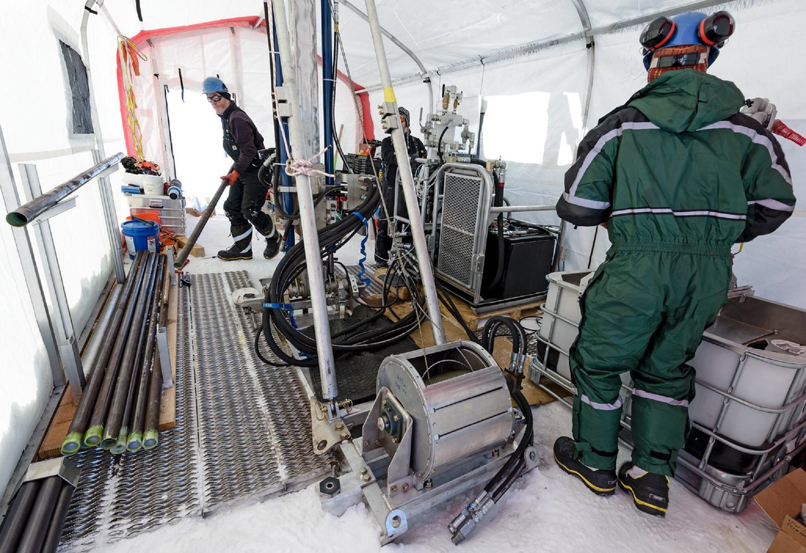
Ice coring operations began the afternoon of 30 December 2016. The hybrid coring bit was used at 300 RPM and 0.18 m min−1 ROP, with normal fluid circulation at 19 L min−1 and ~590 kPa (intermittent spikes to 1030 kPa, measured at the pump outlet). A 1.5 m ice core of poor quality (multiple pieces, internally fractured) was recovered. Coring was unstable, with higher fluid pressure than anticipated. The same downhole equipment and parameters were used the following run, but return drilling fluid flow to the filtration system could not be established at any pump rate. No pressure spikes were registered on the drilling fluid gage. It eventually became clear that the ice surrounding the borehole had fractured, likely very near the hole bottom, and that fluid pumped downhole was flowing into the expanding crack. A conclusive cause of the hydraulic fracturing was not determined, but it was speculated that the crack may have been initiated when the inner core barrel assembly was dropped into the drill string with the fluid level in the pipe ~10 m below the surface (a common practice in rock drilling known as ‘air-mailing’). The resulting pressure pulse exiting the bottom of the drill string may have been sufficient to fracture the surrounding ice, as subsequent testing has suggested (see Section 7). Several attempts were made to deepen the hole to bedrock by reverse-circulation drilling with the full face ice bit, but all attempts ended quickly with the bit plugging completely. Forward-circulation may have been more successful, but it was determined that ‘lost-fluid’ drilling was too risky given the limited supply of drilling fluid on-site. Drilling operations at Site 1 were ceased, as much fluid as possible was bailed from the hole (crack volume decreased as fluid was bailed from the hole, allowing most of the drill fluid to be recovered), and the drill system was disassembled to move to a second site.
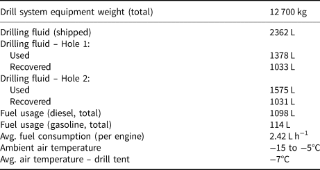
The move to Site 2 was accomplished in 3.5 d total (end of drilling at Site 1 to start of drilling at Site 2) with the aid of the heavy equipment from the tractor traverse so that not all rig components required full disassembly to move. Site 2 was located ~200 m from Site 1 on an estimated 150 m of ice depth. During the drill move, a crate of continuous-flight augers was transported to the field site from McMurdo Station via WAIS Divide by Twin Otter aircraft to speed the drilling of the pilot hole. On 9 January 2017 only 3 h was required to auger to 31 m depth at 300 RPM and nearly 1 m min−1 ROP. Seven meters of ice cuttings remained in the hole bottom following augering. These were cleared and the hole deepened (only 31 m of augers were available) to nearly 34 m depth the following day with the corer assembly. The packer was set in the ice of 870 kg m−3 density and inflated with compressed air to 1100 kPa. On 11 January 2017, access hole drilling commenced with the same drilling parameters as Site 1, down to a depth of 143 m. Ice coring began on 13 January 2017 with the PDC coring bit, which proved to have much improved drilling dynamics (130 RPM, 0.24 m min−1 ROP, 19 L min−1 drilling fluid flow, normal circulation, up to 827 kPa drilling fluid pressure at pump outlet). A total of 4.8 m of poor quality ice core (multiple pieces, internally fractured) was recovered. Bedrock was reached the following day at 149.8 m depth. The same PDC drill bit was used to core the first 5 m of granite (130 RPM, 0.15 m min−1 ROP, 19 L min−1 drilling fluid flow, up to 620 kPa drilling fluid pressure at pump outlet). A diamond-impregnated coring bit was swapped in and used to core the remaining 3 m of granite (300 RPM, 0.06 m min−1 ROP, 19 L min−1 drilling fluid flow, up to 1030 kPa drilling fluid pressure at pump outlet) after the PDC bit wore out. A total of six rock coring runs were required, with 100% core recovery and excellent core quality (Fig. 17). The swab assembly and fluid bailer was used to recover drilling fluid from the borehole before the drill system was disassembled and packed, requiring 3 d, for the return traverse to WAIS Divide. Table 4 lists some additional project data.
Granite bedrock core recovered from Site 2 during the 2016–17 Pirrit Hills, Antarctica field project. Both the PDC and diamond-impregnated bits produced similar quality core.

ASIG Drill system statistics from the Pirrit Hills field project
6. Future work
The Pirrit Hills project identified a variety of deficiencies in the original ASIG Drill system. Primary among these was the drilling fluid filtration system, which has since been upgraded to the shaker table system described earlier. An improved chip melter tank assembly has also been implemented. In addition, a variety of fluid containment devices have been added or upgraded to reduce drilling fluid lost to spills and to protect operators from the fluid spray. Several improvements were made to operator safety, including a cage around the rotating components on the rig mast. Modeling of drilling fluid flow rate and pressure, in normal and reverse circulation, for various borehole geometries and drilling fluids is ongoing to assess depth limits and best-practices for future projects.
7. Hydraulic fracture
Experience with the ASIG and RAID drills has demonstrated the reality of hydraulic fracturing of the ice from the pressurized drilling fluid necessary for these drills to operate. Both percussive shock and excessive pump pressure have resulted in hydraulic fracturing with both systems. Drilling fluid pressure as low as 520 kPa (measured at the pump outlet) has resulted in borehole fracture, although typical fracture pressures have generally been between 1000 and 1380 kPa. Often, it is not possible to record the actual fracture pressure, as pressure spikes can occur very quickly and may not be noticed by the drill operators.
Measures must be taken to ensure high-pressure spikes are not transmitted to the borehole. Use of accurate and reliable pressure-relief valves on the drilling fluid pump outlet has proven invaluable. Adding an accumulator tank to the pump outlet plumbing has also helped dampen the pressure pulses inherent to a piston pump. Conservative drilling practices and operator experience with ice drilling (as opposed to only rock drilling) have also proven important. Borehole pressure models have been developed and continue to be refined in order to make future decisions on equipment, drilling fluids, depth targets and operational parameters (Chen and others, Reference Chen2019). Site selection may also play an important role, as there is evidence that highly stressed ice, such as in shear zones, has a lower fracture threshold than stagnant, unstressed ice. Ice temperature and depth also appear to affect hydraulic fracture potential.
Additional experience is needed with the various drill systems to identify operational best-practices, optimal equipment and pressure thresholds to avoid hydraulic fracture as depth targets increase.
8. Conclusion
The US IDP has developed the capability to reliably drill and recover bedrock core samples of significant length from below several hundred meters of ice with a drill system agile enough to deploy to remote sites with small aircraft. Drill system modularity and scalability makes the ASIG Drill customizable to various project parameters, optimizing project logistics and reducing costs, and allowing the system to be used at sites ranging from inland ice sheets to high-altitude mountain glaciers. Depths of scientific interest can be accessed rapidly with non-coring techniques, where both ice and rock cores can then be drilled and retrieved with wireline coring tools. The system has been designed to maximize project efficiency in the field and limit environmental impacts. Several successful field trials and an Antarctic field season have demonstrated the capabilities of the drill system. Rates of penetration up to 1 m min−1 have been achieved with a non-coring bit in ice. Ten meters of high-quality granite rock core has been recovered through 150 m of overlying ice. Various shortcomings of the original design have been addressed to improve project efficiency, safety and success. Hydraulic fracturing of the ice borehole has been experienced repeatedly and remains a focus of future drill system development. Drill system upgrades and adaptations to meet future scientific project requirements continue.
Acknowledgements
The US Ice Drilling Program thank the US National Science Foundation (NSF) Office of Polar Programs for support of IDP operations, including the development, maintenance and modification of drill systems as well as fieldwork; The University of Wisconsin – Madison, particularly the Space Science and Engineering Center for program support; the Antarctic Support Contract for operational and logistics support in Antarctica; the 109th New York Air National Guard for airlift support in Antarctica; the USAP science cargo team for their cargo support; and the entire Pirrit Hills field team. This work was supported by NSF Cooperative Agreements OPP-0841135 and OPP-1327315.


 Open access