





1. Introduction
When an elastic structure is exposed to a flow, it reconfigures to maintain a deformed quasi-static state by balancing external fluid force and resistive bending force. In most cases, the effective frontal area of the structure decreases because of streamlining deformation, weakening the drag imposed on the structure (Vogel Reference Vogel1984, Reference Vogel1989). Such reconfiguration of elastic structures leads to substantial changes in drag characteristics in comparison to their rigid counterparts and has therefore been widely investigated in the context of drag reduction and drag-based propulsion (i.e. de Langre Reference de Langre2008; Gosselin, de Langre & Machado-Almeida Reference Gosselin, de Langre and Machado-Almeida2010; Luhar & Nepf Reference Luhar and Nepf2011; Leclercq & de Langre Reference Leclercq and de Langre2016; Song et al. Reference Song, Yoo, Ham and Kim2022, Reference Song, Yoo and Kim2023)
As a model of flow-induced reconfiguration, kirigami structures present compelling features. A kirigami structure is a thin, two-dimensional sheet including cutting lines that allow it to undergo significant out-of-plane deformation under external loading and dramatically reconfigure into a three-dimensional form. By virtue of their ability to change shape, accommodate extensive stretching and offer tuneable, effective stiffness through the design of cutting patterns, kirigami structures have been considered for various engineering applications, such as robotic skins, electronics, sensors and actuators (i.e. Blees et al. Reference Blees2015; Firouzeh & Paik Reference Firouzeh and Paik2015; Lamoureux et al. Reference Lamoureux, Lee, Shlian, Forrest and Shtein2015; Wu et al. Reference Wu, Wang, Lin, Guo and Wang2016; Dias et al. Reference Dias, McCarron, Rayneau-Kirkhope, Hanakata, Campbell, Park and Holmes2017; Wang et al. Reference Wang, Li, Rodrigue, Yuan, Han, Cho and Ahn2017; Rafsanjani et al. Reference Rafsanjani, Zhang, Liu, Rubinstein and Bertoldi2018). Recently, kirigami structures have been of interest to the fluid–structure interaction community because their hydrodynamic coupling with a surrounding flow reveals novel phenomena and suggests potential fluid dynamics applications. Marzin et al. (Reference Marzin, Le Hay, de Langre and Ramananarivo2022) experimentally investigated a rectangular kirigami sheet with vertical cutting lines under a uniform flow. As fluid force is applied to the kirigami sheet, reconfiguration occurs, transforming the cutting lines on the two-dimensional sheet into holes on the three-dimensional curved surface. While Marzin et al. (Reference Marzin, Le Hay, de Langre and Ramananarivo2022) focused on structural deformation and its mechanical modelling based on a simple unit structure, Carleton & Modarres-Sadeghi (Reference Carleton and Modarres-Sadeghi2024), who also experimentally examined the interaction of a kirigami sheet with a uniform flow, paid attention to various formation patterns of holes and wake flows in the reconfiguration process, suggesting kirigami sheets as jet generators for the passive control of wake dynamics. Additionally, kirigami structures have been used to design parachutes that can stably descend through the air, taking advantage of their programmable and reconfigurable nature (Lamoureux et al. Reference Lamoureux, Fillion, Ramananarivo, Gosselin and Melancon2025a ).
In the fluid–structure interactions of deformable porous structures such as kirigami structures, the size and distribution of holes (or gaps) within the structure, collectively referred to as porosity, play a crucial role in determining the characteristics of structural deformation and drag (Gosselin & de Langre Reference Gosselin and de Langre2011; Jin et al. Reference Jin, Kim, Cheng, Barry and Chamorro2020). While an incoming flow penetrates directly through the gap of the structure in the high-Reynolds-number flow regime, in the low-Reynolds-number flow regime, thicker shear layers develop and overlap in the gap within the structure because of strong viscous diffusion, forming a virtual fluid barrier in the gap (Nawroth et al. Reference Nawroth, Feitl, Colin, Costello and Dabiri2010). This phenomenon, known as hydrodynamic blockage, has drawn attention in the fields of low-Reynolds-number aerodynamics and hydrodynamics, particularly in the bio-inspired aerodynamics of bristled wings found in small-scale insects (i.e. Sunada et al. Reference Sunada, Takashima, Hattori, Yasuda and Kawachi2002; Weihs & Barta Reference Weihs and Barta2008; Santhanakrishnan et al. Reference Santhanakrishnan, Robinson, Jones, Lowe, Gadi, Hedrick and Miller2014; Lee & Kim Reference Lee and Kim2017; Lee et al. Reference Lee, Lahooti and Kim2018, Reference Lee, Lee and Kim2020b ; Lee & Kim Reference Lee and Kim2021; Luna Lin, Pezzulla & Reis Reference Luna Lin, Pezzulla and Reis2023).
(a) Schematic of the experimental set-up. The dotted line indicates the initial flat configuration of the kirigami sheet and the solid line indicates the outline of the kirigami sheet after flow-induced reconfiguration. (b) Two-dimensional design of the kirigami sheet and rigid frame. The thick black line represents the rigid frame and the red square represents the unit structure of the sheet. (c) Cutting lines in the unit structure. (d) Definition of cutting angle $\theta _{c}$
and non-cutting angle
$\theta _{c}$
and non-cutting angle $\theta _{nc}$
for the unit structure; the red line marks the boundary between the cutting and non-cutting regions. (e) Cutting lines for (i) the minimum (
$\theta _{nc}$
for the unit structure; the red line marks the boundary between the cutting and non-cutting regions. (e) Cutting lines for (i) the minimum ( $\gamma = 2.6$
) and (ii) the maximum (
$\gamma = 2.6$
) and (ii) the maximum ( $\gamma = 8.0$
) cutting ratios.
$\gamma = 8.0$
) cutting ratios.

Recently, Lee, Mahravan & Kim (Reference Lee, Mahravan and Kim2024) studied an array of elastically mounted cylinders arranged in a circular configuration, incorporating both porosity and elasticity to elucidate their combined effects on hydrodynamic blockage at low Reynolds number. Hydrodynamic blockage strongly affects the rearrangement of the cylinders, increasing the frontal area of the entire array and the resultant total drag, highlighting the importance of viscous diffusion in the fluid-dynamic performance of a deformable porous structure at the low Reynolds number. However, the inherent configuration of this cylinder-array model limits the degree of deformation in the overall array shape and the range of achievable porosity in the deformed quasi-static state. A new model is needed to deepen our understanding of flow-induced reconfiguration and hydrodynamic blockage effects at low Reynolds number. Kirigami structures undergo structural deformation and simultaneously form holes under fluid forces, exhibiting features of both elasticity and porosity. Furthermore, because deformation is enabled by cutting lines, kirigami structures can easily achieve large deformation without requiring extreme conditions such as high pressure (Gehrke, King & Breuer Reference Gehrke, King and Breuer2025) or high fluid velocity. The flow structure and drag characteristics of kirigami structures at low Reynolds number are expected to differ significantly from those reported in previous studies for the interaction between high-Reynolds-number flows and kirigami structures (Marzin et al. Reference Marzin, Le Hay, de Langre and Ramananarivo2022; Carleton & Modarres-Sadeghi Reference Carleton and Modarres-Sadeghi2024; Lamoureux et al. Reference Lamoureux, Fillion, Ramananarivo, Gosselin and Melancon2025a ).
In this study, we experimentally investigate the flow-induced reconfiguration of a kirigami sheet moving in the flow with strong viscous diffusion. The model is initially immersed in a highly viscous fluid and translates at a constant velocity, eventually undergoing quasi-static deformation (figure 1 a). By elucidating the correlation between reconfiguration, hydrodynamic blockage and drag generation, this work aims to explore fluid-dynamic design principles for the potential use of kirigami sheets in small-scale transport and propulsion systems operating in high-viscosity environments. The kirigami sheet designs and experimental procedures are described in § 2. In § 3.1, the flow distribution in the wake of a kirigami sheet is compared with that at high Reynolds number to emphasise hydrodynamic blockage effects. The deflection and porosity of the deformed kirigami sheet are characterised by a dimensionless parameter derived from the force balance in § 3.2. Section 3.3 examines the drag generated by the deformed kirigami sheet and discusses the implications of the hydrodynamic blockage effects. Finally, concluding remarks are presented in § 4.
2. Experimental set-up
Two glass tanks with dimensions 1200 mm $\times$
490 mm and a water level of 300 mm were constructed to contain two different working fluids: glycerine and water, used for low- and high-Reynolds-number conditions, respectively. The kinematic viscosity
$\times$
490 mm and a water level of 300 mm were constructed to contain two different working fluids: glycerine and water, used for low- and high-Reynolds-number conditions, respectively. The kinematic viscosity $\nu$
and density
$\nu$
and density $\rho _{\kern-1pt f}$
of the glycerine were 1306 mm
$\rho _{\kern-1pt f}$
of the glycerine were 1306 mm $^{2}$
s
$^{2}$
s $^{-1}$
and
$^{-1}$
and $1.26\times 10^3$
kg m
$1.26\times 10^3$
kg m $^{-3}$
, respectively, at room temperature (20
$^{-3}$
, respectively, at room temperature (20 $^\circ$
C), and those of the water were 1.0 mm
$^\circ$
C), and those of the water were 1.0 mm $^{2}$
s
$^{2}$
s $^{-1}$
and
$^{-1}$
and $9.98\times 10^2$
kg m
$9.98\times 10^2$
kg m $^{-3}$
. An initially flat kirigami sheet was mounted vertically and connected to the block of a linear guide (LST10-1000-T56.4, MISUMI Inc.) positioned above the tank (figure 1
a). The linear guide block was driven by a stepper motor through a motor driver (MW-VSTB24D3S-v2, NTREX.) and a data acquisition board (PCIe-6321, National Instruments Co.) with motion prescribed by a MATLAB code (The MathWorks, Inc.) to produce steady translation in the quiescent fluid. The translation speed
$^{-3}$
. An initially flat kirigami sheet was mounted vertically and connected to the block of a linear guide (LST10-1000-T56.4, MISUMI Inc.) positioned above the tank (figure 1
a). The linear guide block was driven by a stepper motor through a motor driver (MW-VSTB24D3S-v2, NTREX.) and a data acquisition board (PCIe-6321, National Instruments Co.) with motion prescribed by a MATLAB code (The MathWorks, Inc.) to produce steady translation in the quiescent fluid. The translation speed $U$
(to the left in figure 1
a) varied between 5.0 and 20.0 cm s
$U$
(to the left in figure 1
a) varied between 5.0 and 20.0 cm s $^{-1}$
, and the total travel distance of each case was fixed as 60 cm. To ensure smooth acceleration at the start of each case, a quarter-sinusoidal velocity profile was applied over the first 10 cm of displacement. The flow was allowed to rest for several minutes between successive runs to eliminate residual disturbance.
$^{-1}$
, and the total travel distance of each case was fixed as 60 cm. To ensure smooth acceleration at the start of each case, a quarter-sinusoidal velocity profile was applied over the first 10 cm of displacement. The flow was allowed to rest for several minutes between successive runs to eliminate residual disturbance.
Throughout this study, a closed-loop kirigami sheet (Carleton & Modarres-Sadeghi Reference Carleton and Modarres-Sadeghi2024; Lamoureux et al. Reference Lamoureux, Fillion, Ramananarivo, Gosselin and Melancon2025a
) was considered with radially spaced cutting lines (figure 1
b). The kirigami patterns were fabricated by laser-cutting silicon rubber (Young’s modulus $E$
=
$E$
= $2.0\times 10^6$
N m
$2.0\times 10^6$
N m $^{-2}$
, Poisson’s ratio 0.49, density
$^{-2}$
, Poisson’s ratio 0.49, density $2.3\times 10^3$
kg m
$2.3\times 10^3$
kg m $^{-3}$
) with four different sheet thickness values of
$^{-3}$
) with four different sheet thickness values of $h$
= [0.3, 0.4, 0.5, 0.6] mm. To satisfy needs for both a finite (non-negligible) bending stiffness and negligible in-plane tension, we selected silicone rubber. This material allows us to systematically vary the bending stiffness across a broad range by changing its thickness. Furthermore, although silicone rubber can stretch generally, we confirmed that no measurable in-plane stretching occurred under our experimental conditions. A rigid frame in the shape of a circular ring was constructed to clamp the edges of the circular kirigami sheet. The inner and outer diameters of the rigid ring frame were 100 and 120 mm, respectively. A vertical rigid frame connected the top of the rigid ring frame to a load cell above the free surface. Although the rigid frame clamping the kirigami structure was initially aligned vertically, slight tilting of the rigid frame was observed as it translated through the fluid. However, the maximum tilt angle was 4
$h$
= [0.3, 0.4, 0.5, 0.6] mm. To satisfy needs for both a finite (non-negligible) bending stiffness and negligible in-plane tension, we selected silicone rubber. This material allows us to systematically vary the bending stiffness across a broad range by changing its thickness. Furthermore, although silicone rubber can stretch generally, we confirmed that no measurable in-plane stretching occurred under our experimental conditions. A rigid frame in the shape of a circular ring was constructed to clamp the edges of the circular kirigami sheet. The inner and outer diameters of the rigid ring frame were 100 and 120 mm, respectively. A vertical rigid frame connected the top of the rigid ring frame to a load cell above the free surface. Although the rigid frame clamping the kirigami structure was initially aligned vertically, slight tilting of the rigid frame was observed as it translated through the fluid. However, the maximum tilt angle was 4 $^{\circ }$
, which is sufficiently small to justify that the sheet is deflected along the
$^{\circ }$
, which is sufficiently small to justify that the sheet is deflected along the $x$
-axis.
$x$
-axis.
Due to the circular geometry, the unit structure of the kirigami sheet was chosen by dividing it into four equal segments, as depicted in figure 1(c). Because the angle of the unit structure was $90^{\circ }$
, adjacent cutting lines in the unit structure were rotated by
$90^{\circ }$
, adjacent cutting lines in the unit structure were rotated by $45^{\circ }$
(= half the angle of the unit structure) to create a pattern with adjacent cutting lines staggered. The diameter of the circular sheet was
$45^{\circ }$
(= half the angle of the unit structure) to create a pattern with adjacent cutting lines staggered. The diameter of the circular sheet was $D$
= 100 mm and the distance between adjacent cutting lines was
$D$
= 100 mm and the distance between adjacent cutting lines was $d$
= 5 mm. The sum of cutting angle
$d$
= 5 mm. The sum of cutting angle $\theta _{c}$
and non-cutting angle
$\theta _{c}$
and non-cutting angle $\theta _{nc}$
was equal to
$\theta _{nc}$
was equal to $90^{\circ }$
(figure 1
d). To investigate the effect of the kirigami pattern, four different cutting angles
$90^{\circ }$
(figure 1
d). To investigate the effect of the kirigami pattern, four different cutting angles $\theta _{c}$
= [65, 70, 75, 80]
$\theta _{c}$
= [65, 70, 75, 80] $^{\circ }$
were considered, with corresponding non-cutting angles of
$^{\circ }$
were considered, with corresponding non-cutting angles of $\theta _{nc}$
= [25, 20, 15, 10]
$\theta _{nc}$
= [25, 20, 15, 10] $^{\circ }$
, respectively. To characterise the kirigami pattern, a ratio between the cutting and non-cutting regions was defined as the cutting ratio
$^{\circ }$
, respectively. To characterise the kirigami pattern, a ratio between the cutting and non-cutting regions was defined as the cutting ratio $\gamma = \theta _{c}/\theta _{nc}$
. The cutting ratios for the four different models were 2.6, 3.5, 5.0 and 8.0, respectively (figure 1
e).
$\gamma = \theta _{c}/\theta _{nc}$
. The cutting ratios for the four different models were 2.6, 3.5, 5.0 and 8.0, respectively (figure 1
e).
The Reynolds number is based on the translational speed and diameter of the kirigami sheet ( $ \textit{Re}_{D}= \textit{UD}/\nu$
) and ranged from 4 to 15 for glycerine and 5000–20 000 for water. In studies of hydrodynamic blockage at low Reynolds number, the gap distance within the structure was found to better characterise the effects of hydrodynamic blockage than the length of the entire structure (Lee, Lee & Kim Reference Lee, Lee and Kim2020b
; Lee & Kim Reference Lee and Kim2024). However, because the gap (hole) in the kirigami sheet cannot be predetermined, its diameter
$ \textit{Re}_{D}= \textit{UD}/\nu$
) and ranged from 4 to 15 for glycerine and 5000–20 000 for water. In studies of hydrodynamic blockage at low Reynolds number, the gap distance within the structure was found to better characterise the effects of hydrodynamic blockage than the length of the entire structure (Lee, Lee & Kim Reference Lee, Lee and Kim2020b
; Lee & Kim Reference Lee and Kim2024). However, because the gap (hole) in the kirigami sheet cannot be predetermined, its diameter $D$
was used instead of the gap for the Reynolds number. Alternatively, the characteristic length for the Reynolds number could be chosen as the cutting line spacing
$D$
was used instead of the gap for the Reynolds number. Alternatively, the characteristic length for the Reynolds number could be chosen as the cutting line spacing $d$
instead of
$d$
instead of $D$
, reducing the corresponding
$D$
, reducing the corresponding $ \textit{Re}_d$
to the ranges of 0.20–0.75 and 250–1000 for glycerine and water, respectively. The cutting line spacing
$ \textit{Re}_d$
to the ranges of 0.20–0.75 and 250–1000 for glycerine and water, respectively. The cutting line spacing $d$
is more closely related to the hole size and may be a better characteristic length for hydrodynamic blockage than the diameter
$d$
is more closely related to the hole size and may be a better characteristic length for hydrodynamic blockage than the diameter $D$
. Nevertheless,
$D$
. Nevertheless, $ \textit{Re}_D$
will be used consistently in this study, as the conversion to
$ \textit{Re}_D$
will be used consistently in this study, as the conversion to $ \textit{Re}_d$
is straightforward.
$ \textit{Re}_d$
is straightforward.
A high-speed camera (FASTCAM MINI-UX50, Photron, Inc.) with a resolution of $1280\times 1024$
pixels was employed to capture the deformed shape of the kirigami sheet at 250 frames per second. The image plane was illuminated using a light-emitting diode lamp. A load cell (MB-5, Interface Inc.) was attached between the linear guide and the model to obtain the drag force acting on the combination of the kirigami sheet and rigid frame (figure 1
a). The load cell was calibrated with various static loads and exhibited repeatable, reliable results. A quasi-steady drag force was acquired at a sampling rate of 100 Hz by taking the arithmetic mean of the measured values over a certain period of the constant translational speed (roughly 1–3 s), during which the time series data of the force formed a plateau. The time history of the force showed minor variations during steady translation, and the standard deviation of the drag during the plateau was less than 5.2 % of its mean value. To eliminate the effect of the submerged rigid frame connecting the kirigami sheet to the linear guide, force measurements were also conducted without the kirigami sheet and with only the rigid frame. By subtracting the force measured in the absence of the kirigami sheet from the force measured with it present, the drag force of the kirigami sheet alone could be obtained. Force measurements were repeated three times, and the standard deviation was within 4.8 % and 6.7 % of the mean for the water and glycerine cases, respectively.
$1280\times 1024$
pixels was employed to capture the deformed shape of the kirigami sheet at 250 frames per second. The image plane was illuminated using a light-emitting diode lamp. A load cell (MB-5, Interface Inc.) was attached between the linear guide and the model to obtain the drag force acting on the combination of the kirigami sheet and rigid frame (figure 1
a). The load cell was calibrated with various static loads and exhibited repeatable, reliable results. A quasi-steady drag force was acquired at a sampling rate of 100 Hz by taking the arithmetic mean of the measured values over a certain period of the constant translational speed (roughly 1–3 s), during which the time series data of the force formed a plateau. The time history of the force showed minor variations during steady translation, and the standard deviation of the drag during the plateau was less than 5.2 % of its mean value. To eliminate the effect of the submerged rigid frame connecting the kirigami sheet to the linear guide, force measurements were also conducted without the kirigami sheet and with only the rigid frame. By subtracting the force measured in the absence of the kirigami sheet from the force measured with it present, the drag force of the kirigami sheet alone could be obtained. Force measurements were repeated three times, and the standard deviation was within 4.8 % and 6.7 % of the mean for the water and glycerine cases, respectively.
Furthermore, planar particle image velocimetry (PIV) was conducted to obtain the flow field near the reconfigured kirigami sheet in the quasi-steady state. Micro polypropylene spherical particles with an average diameter of 50 $\mu$
m and an average density of
$\mu$
m and an average density of $1.06\times 10^3$
kg m
$1.06\times 10^3$
kg m $^{-3}$
were seeded into the glass tank. A 10 W continuous laser (MGL-W-532A, CNI Co.) illuminated the particles and images were recorded using the same high-speed camera. Because of the circular geometry and cutting lines of the sheet, the
$^{-3}$
were seeded into the glass tank. A 10 W continuous laser (MGL-W-532A, CNI Co.) illuminated the particles and images were recorded using the same high-speed camera. Because of the circular geometry and cutting lines of the sheet, the $xy$
-plane for PIV was placed to include the centre of the sheet. The frame rate was set to 250 frames per second, corresponding to a time interval of 0.004 s between two images in a pair. PIVview2C software (PIVTEC GmbH) was used to cross-correlate the image pairs. The total fluid domain size was 315 mm in width and 252 mm in height on the
$xy$
-plane for PIV was placed to include the centre of the sheet. The frame rate was set to 250 frames per second, corresponding to a time interval of 0.004 s between two images in a pair. PIVview2C software (PIVTEC GmbH) was used to cross-correlate the image pairs. The total fluid domain size was 315 mm in width and 252 mm in height on the $xy$
-plane. In the multi-grid interrogation method, the initial window size was 32
$xy$
-plane. In the multi-grid interrogation method, the initial window size was 32 $\times$
32 pixels with 50 % overlap, which was reduced to 16
$\times$
32 pixels with 50 % overlap, which was reduced to 16 $\times$
16 pixels.
$\times$
16 pixels.
3. Results and discussion
3.1. Flow distribution
First, we justify the process of selecting the circular kirigami sheet described in § 2 as an experimental model. Although not included in this paper, preliminary experiments were conducted with a rectangular ribbon-type kirigami sheet with transverse cutting lines, the configuration adopted by Marzin et al. (Reference Marzin, Le Hay, de Langre and Ramananarivo2022). These experiments at high Reynolds number with water as the working fluid revealed that when the fluid force exceeds a certain threshold, the sheet undergoes complex three-dimensional deformation to resemble a saddle shape. With this model, however, it is difficult to quantify deformation and porosity. The porosity of the sheet is determined by transforming the cutting lines in the initial flat sheet into the holes of a complex, three-dimensional curved surface. Furthermore, due to the geometrical complexity of the structure, force balance analysis is also challenging. For these reasons, we adopted the circular kirigami sheet described by Carleton & Modarres-Sadeghi (Reference Carleton and Modarres-Sadeghi2024). Its initial two-dimensional planar shape satisfies both point and line symmetry, and its three-dimensional deformed shape retains axisymmetry as it undergoes steady translation in the quiescent fluid (figure 2). This axisymmetric geometry makes the quantification of kirigami sheet deformation easier and enables the estimation of porosity from the surface area and its variation.
Raw images of the reconfigured kirigami sheet of diameter $D$
= 100 mm during steady translation at four different translation speeds
$D$
= 100 mm during steady translation at four different translation speeds $U$
: (a)
$U$
: (a) $U$
= 5.0 cm s
$U$
= 5.0 cm s $^{-1}$
; (b)
$^{-1}$
; (b) $U$
= 10.0 cm s
$U$
= 10.0 cm s $^{-1}$
; (c)
$^{-1}$
; (c) $U$
= 15.0 cm s
$U$
= 15.0 cm s $^{-1}$
; (d)
$^{-1}$
; (d) $U$
= 20.0 cm s
$U$
= 20.0 cm s $^{-1}$
(sheet thickness
$^{-1}$
(sheet thickness $h$
= 0.4 mm, cutting ratio
$h$
= 0.4 mm, cutting ratio $\gamma$
= 5.0).
$\gamma$
= 5.0).

For a specific kirigami sheet with the fixed sheet thickness $h$
and cutting ratio
$h$
and cutting ratio $\gamma$
, the effect of the translation speed
$\gamma$
, the effect of the translation speed $U$
on quasi-static deformation is briefly reported for the cases of low Reynolds number (with glycerine as the working fluid). At the lowest translation speed tested in this study (
$U$
on quasi-static deformation is briefly reported for the cases of low Reynolds number (with glycerine as the working fluid). At the lowest translation speed tested in this study ( $U$
= 5.0 cm s
$U$
= 5.0 cm s $^{-1}$
), a relatively small deformation is observed in the quasi-steady state (figure 2
a). Even though this deformation is the smallest among the tested cases, the cutting line at the edge of the circular sheet clearly transitions into a hole, with a three-dimensional, axisymmetric curved surface. The extent of this deformation becomes greater as the translation speed increases. The holes of the sheet continue to grow as the translation speed
$^{-1}$
), a relatively small deformation is observed in the quasi-steady state (figure 2
a). Even though this deformation is the smallest among the tested cases, the cutting line at the edge of the circular sheet clearly transitions into a hole, with a three-dimensional, axisymmetric curved surface. The extent of this deformation becomes greater as the translation speed increases. The holes of the sheet continue to grow as the translation speed $U$
increases further (figure 2
b–d). This pronounced axisymmetric deformation in the quasi-steady state is clearly distinct from those reported in previous studies. Compared with the work of Carleton & Modarres-Sadeghi (Reference Carleton and Modarres-Sadeghi2024), the present circular sheet also exhibits axisymmetric deformation owing to the clamping of the outer edge by a rigid frame. However, since their working fluid was water, the Reynolds number range was significantly higher than in the present study, producing some oscillations that prevented the sheet from maintaining a truly quasi-static configuration. Lamoureux et al. (Reference Lamoureux, Fillion, Ramananarivo, Gosselin and Melancon2025a
) enforced a boundary condition that fixed the centre of the circular kirigami sheet, under which the kirigami sheet could exhibit non-axisymmetric deformation due to much higher Reynolds number.
$U$
increases further (figure 2
b–d). This pronounced axisymmetric deformation in the quasi-steady state is clearly distinct from those reported in previous studies. Compared with the work of Carleton & Modarres-Sadeghi (Reference Carleton and Modarres-Sadeghi2024), the present circular sheet also exhibits axisymmetric deformation owing to the clamping of the outer edge by a rigid frame. However, since their working fluid was water, the Reynolds number range was significantly higher than in the present study, producing some oscillations that prevented the sheet from maintaining a truly quasi-static configuration. Lamoureux et al. (Reference Lamoureux, Fillion, Ramananarivo, Gosselin and Melancon2025a
) enforced a boundary condition that fixed the centre of the circular kirigami sheet, under which the kirigami sheet could exhibit non-axisymmetric deformation due to much higher Reynolds number.
To clarify the relationship between boundary conditions and the reconfiguration of the circular kirigami sheet, additional experiments were conducted using a rigid frame that fixed only the centre of the sheet with its outer edge free. According to the experiments, the boundary condition has a substantial influence on the reconfiguration behaviour. For relatively thin sheets (i.e. with low bending stiffness), large deformation leads to a breakdown of axisymmetry. In contrast, for thicker sheets (i.e. with high bending stiffness), cutting lines do not reconfigure into holes; instead, the structure deforms in a manner analogous to the bending of an elastic circular disk interacting with a high-Reynolds-number flow (Schouveiler & Eloy Reference Schouveiler and Eloy2013; Lamoureux et al. Reference Lamoureux, Fillion, Ramananarivo, Gosselin and Melancon2025a ). These findings indicate that the axisymmetric deformation observed in the present study is governed primarily by the edge-clamped boundary condition, rather than by the Reynolds-number regime.
The velocity field around the reconfigured kirigami sheet in the quasi-steady state provides important insights into the deformation and drag generation of the sheet at low Reynolds number. For flow visualisation on the $xy$
-plane passing through the centre of the sheet, two cases were considered as representatives: the small-deflection case ([
$xy$
-plane passing through the centre of the sheet, two cases were considered as representatives: the small-deflection case ([ $U$
,
$U$
, $h$
,
$h$
, $\gamma$
] = [15.0 cm s
$\gamma$
] = [15.0 cm s $^{-1}$
, 0.6 mm, 3.5]) and the large-deflection case ([
$^{-1}$
, 0.6 mm, 3.5]) and the large-deflection case ([ $U$
,
$U$
, $h$
,
$h$
, $\gamma$
] = [15.0 cm s
$\gamma$
] = [15.0 cm s $^{-1}$
, 0.3 mm, 8.0]). In addition to the kirigami sheet, a solid shell structure with zero porosity was used as a reference model. Based on the quasi-static deformation profile of the kirigami sheet, a corresponding solid shell model was approximated to be an ideal truncated cone and fabricated using a three-dimensional (3-D) printer (ProJet MJP 2500, 3D SYSTEMS Inc.); the approximation of the deformed shape as the truncated cone is detailed in § 3.2. In the experiments, the fluid in the tank was initially stationary, while the rigid frame to which the kirigami sheet was attached was mechanically translated. For convenience of analysis, the coordinate system is fixed to the rigid frame hereafter, and in this coordinate system, the uniform free stream of velocity
$^{-1}$
, 0.3 mm, 8.0]). In addition to the kirigami sheet, a solid shell structure with zero porosity was used as a reference model. Based on the quasi-static deformation profile of the kirigami sheet, a corresponding solid shell model was approximated to be an ideal truncated cone and fabricated using a three-dimensional (3-D) printer (ProJet MJP 2500, 3D SYSTEMS Inc.); the approximation of the deformed shape as the truncated cone is detailed in § 3.2. In the experiments, the fluid in the tank was initially stationary, while the rigid frame to which the kirigami sheet was attached was mechanically translated. For convenience of analysis, the coordinate system is fixed to the rigid frame hereafter, and in this coordinate system, the uniform free stream of velocity $U$
flows along the positive
$U$
flows along the positive $x$
-axis.
$x$
-axis.
We first examine the flow distribution for the small-deflection case with relatively small deformation (figure 3). In the low-Reynolds-number regime ( $ \textit{Re}_D$
= 12), because of strong viscous diffusion and the absence of flow separation at the edge of the solid shell model, the
$ \textit{Re}_D$
= 12), because of strong viscous diffusion and the absence of flow separation at the edge of the solid shell model, the $x$
-directional velocity relative to the rigid frame,
$x$
-directional velocity relative to the rigid frame, $u_{\textit{rel}}/U$
, is positive behind the solid shell, roughly ranging from 0.2 to 0.4 (figure 3
ai). When the wakes at low
$u_{\textit{rel}}/U$
, is positive behind the solid shell, roughly ranging from 0.2 to 0.4 (figure 3
ai). When the wakes at low $ \textit{Re}_D$
are compared between the solid shell and the kirigami sheet, no significant difference is identified (figure 3
aii). This similarity can be attributed to relatively low porosity and viscosity-induced hydrodynamic blockage within the holes of the kirigami sheet. In contrast, in the high-Reynolds-number regime (
$ \textit{Re}_D$
are compared between the solid shell and the kirigami sheet, no significant difference is identified (figure 3
aii). This similarity can be attributed to relatively low porosity and viscosity-induced hydrodynamic blockage within the holes of the kirigami sheet. In contrast, in the high-Reynolds-number regime ( $ \textit{Re}_{D}$
= 15 000), a region where
$ \textit{Re}_{D}$
= 15 000), a region where $u_{\textit{rel}}/U$
has negative values below
$u_{\textit{rel}}/U$
has negative values below $-0.2$
is widely distributed downstream of the solid shell model (white region in figure 3
bi). Even at high
$-0.2$
is widely distributed downstream of the solid shell model (white region in figure 3
bi). Even at high $ \textit{Re}_D$
, the
$ \textit{Re}_D$
, the $x$
-velocity distributions of the solid shell and the kirigami sheet appear to be similar (figure 3
bii). In the small-deflection case, the structural deformation of the kirigami sheet is relatively small, resulting in low porosity (
$x$
-velocity distributions of the solid shell and the kirigami sheet appear to be similar (figure 3
bii). In the small-deflection case, the structural deformation of the kirigami sheet is relatively small, resulting in low porosity ( $\phi =0.12$
); the definition of porosity is provided in § 3.2. When the degree of deformation and the porosity are sufficiently low, the
$\phi =0.12$
); the definition of porosity is provided in § 3.2. When the degree of deformation and the porosity are sufficiently low, the $x$
-directional flow is effectively blocked by the kirigami sheet, detouring along the
$x$
-directional flow is effectively blocked by the kirigami sheet, detouring along the $y$
-direction. Thus, the distribution of
$y$
-direction. Thus, the distribution of $u_{\textit{rel}}/U$
at high
$u_{\textit{rel}}/U$
at high $ \textit{Re}_D$
does not show a significant difference from that of the solid shell model, although the viscosity-induced hydrodynamic blockage is absent.
$ \textit{Re}_D$
does not show a significant difference from that of the solid shell model, although the viscosity-induced hydrodynamic blockage is absent.
Superimposed images of the model and the normalised relative $x$
-velocity field
$x$
-velocity field $u_{\textit{rel}}/U$
for the small-deflection case of [
$u_{\textit{rel}}/U$
for the small-deflection case of [ $U$
,
$U$
, $h$
,
$h$
, $\gamma$
] = [15.0 cm s
$\gamma$
] = [15.0 cm s $^{-1}$
, 0.6 mm, 3.5]: (a)
$^{-1}$
, 0.6 mm, 3.5]: (a) $ \textit{Re}_{D}$
= 12 and (b)
$ \textit{Re}_{D}$
= 12 and (b) $ \textit{Re}_{D}$
= 15 000. Panels (i) and (ii) present the results of the corresponding solid shell and the kirigami sheet, respectively. A reference frame is fixed with the kirigami sheet.
$ \textit{Re}_{D}$
= 15 000. Panels (i) and (ii) present the results of the corresponding solid shell and the kirigami sheet, respectively. A reference frame is fixed with the kirigami sheet.

Superimposed images of the model and the normalised relative $x$
-velocity field
$x$
-velocity field $u_{\textit{rel}}/U$
for the large-deflection case of [
$u_{\textit{rel}}/U$
for the large-deflection case of [ $U$
,
$U$
, $h$
,
$h$
, $\gamma$
] = [15.0 cm s
$\gamma$
] = [15.0 cm s $^{-1}$
, 0.3 mm, 8.0]: (a)
$^{-1}$
, 0.3 mm, 8.0]: (a) $ \textit{Re}_{D}$
= 12 and (b)
$ \textit{Re}_{D}$
= 12 and (b) $ \textit{Re}_{D}$
= 15 000. Panels (i) and (ii) present the results of the corresponding solid shell and the kirigami sheet, respectively. A reference frame is fixed with the kirigami sheet.
$ \textit{Re}_{D}$
= 15 000. Panels (i) and (ii) present the results of the corresponding solid shell and the kirigami sheet, respectively. A reference frame is fixed with the kirigami sheet.

Superimposed images of the model and the normalised relative $y$
-velocity field
$y$
-velocity field $v_{\textit{rel}}/U$
: (a)
$v_{\textit{rel}}/U$
: (a) $ \textit{Re}_{D}$
= 12 and (b)
$ \textit{Re}_{D}$
= 12 and (b) $ \textit{Re}_{D}$
= 15 000. Panels (i) and (ii) are for the small-deflection case ([
$ \textit{Re}_{D}$
= 15 000. Panels (i) and (ii) are for the small-deflection case ([ $U$
,
$U$
, $h$
,
$h$
, $\gamma$
] = [15.0 cm s
$\gamma$
] = [15.0 cm s $^{-1}$
, 0.6 mm, 3.5]) and the large-deflection case ([
$^{-1}$
, 0.6 mm, 3.5]) and the large-deflection case ([ $U$
,
$U$
, $h$
,
$h$
, $\gamma$
] = [15.0 cm s
$\gamma$
] = [15.0 cm s $^{-1}$
, 0.3 mm, 8.0]), respectively.
$^{-1}$
, 0.3 mm, 8.0]), respectively.

The effect of hydrodynamic blockage on the velocity field is more pronounced in the large-deflection case, with relatively large deformation and an increased hole size. Despite a notable hole size within the kirigami sheet and high porosity ( $\phi =0.52$
), the overall flow distribution is similar to that of the solid shell model at low
$\phi =0.52$
), the overall flow distribution is similar to that of the solid shell model at low $ \textit{Re}_D$
(figure 4
a). This result is consistent with the hydrodynamic blockage effect reported in previous studies using highly porous models (Lee & Kim Reference Lee and Kim2017; Lee et al. Reference Lee, Lee and Kim2020a
,Reference Lee, Lee and Kim
b
, Reference Lee, Mahravan and Kim2024). The notion of hydrodynamic blockage does not refer to the flow being physically obstructed by a solid bluff structure. Rather, for a porous structure, the overlap of thick shear layers in the low-Reynolds-number regime can give rise to a virtual fluid barrier even when holes or gaps are present, which makes the structure hydrodynamically opaque. Through this hydrodynamic blockage, the structure regulates its overall flow permeability, thereby preventing the fluid from penetrating the gaps and, instead, forcing it to bypass them. However, at high
$ \textit{Re}_D$
(figure 4
a). This result is consistent with the hydrodynamic blockage effect reported in previous studies using highly porous models (Lee & Kim Reference Lee and Kim2017; Lee et al. Reference Lee, Lee and Kim2020a
,Reference Lee, Lee and Kim
b
, Reference Lee, Mahravan and Kim2024). The notion of hydrodynamic blockage does not refer to the flow being physically obstructed by a solid bluff structure. Rather, for a porous structure, the overlap of thick shear layers in the low-Reynolds-number regime can give rise to a virtual fluid barrier even when holes or gaps are present, which makes the structure hydrodynamically opaque. Through this hydrodynamic blockage, the structure regulates its overall flow permeability, thereby preventing the fluid from penetrating the gaps and, instead, forcing it to bypass them. However, at high $ \textit{Re}_D$
, the incoming flow penetrates the holes of the kirigami sheet, producing localised regions of strong
$ \textit{Re}_D$
, the incoming flow penetrates the holes of the kirigami sheet, producing localised regions of strong $x$
-velocity
$x$
-velocity $u_{\textit{rel}}/U$
near the holes. Thus, the velocity distribution differs significantly from that of the solid shell model (figure 4
b).
$u_{\textit{rel}}/U$
near the holes. Thus, the velocity distribution differs significantly from that of the solid shell model (figure 4
b).
The dependence of the $y$
-velocity distribution on the Reynolds number is examined in addition to the
$y$
-velocity distribution on the Reynolds number is examined in addition to the $x$
-velocity. At
$x$
-velocity. At $ \textit{Re}_D$
= 12, the normalised
$ \textit{Re}_D$
= 12, the normalised $y$
-velocity
$y$
-velocity $v_{\textit{rel}}/U$
near the holes ranges roughly from
$v_{\textit{rel}}/U$
near the holes ranges roughly from $-0.2$
to 0.2 for both the small-deflection case and the large-deflection case, demonstrating the effective hydrodynamic blockage (figure 5
a). By contrast, at
$-0.2$
to 0.2 for both the small-deflection case and the large-deflection case, demonstrating the effective hydrodynamic blockage (figure 5
a). By contrast, at $ \textit{Re}_D$
= 15 000, regions of high
$ \textit{Re}_D$
= 15 000, regions of high $y$
-velocity emerge in the vicinity of the holes, having upward velocity in the
$y$
-velocity emerge in the vicinity of the holes, having upward velocity in the $y\gt 0$
domain and downward velocity in the
$y\gt 0$
domain and downward velocity in the $y\lt 0$
domain (figure 5
b). The magnitude of the
$y\lt 0$
domain (figure 5
b). The magnitude of the $y$
-velocity varies with the extent of sheet deformation. For the case of smaller deformation, the flow velocity through the holes is higher due to the reduced hole size, considering that the total flow rate through the entire sheet remains similar at high
$y$
-velocity varies with the extent of sheet deformation. For the case of smaller deformation, the flow velocity through the holes is higher due to the reduced hole size, considering that the total flow rate through the entire sheet remains similar at high $ \textit{Re}_D$
regardless of the extent of deformation. Accordingly, the magnitude of
$ \textit{Re}_D$
regardless of the extent of deformation. Accordingly, the magnitude of $v_{\textit{rel}}/U$
around the holes in the large-deflection case (figure 5
bii) is generally smaller than that in the small-deflection case (figure 5
bi). Even when the kirigami sheet reaches quasi-static deformation, the corresponding wake flow can be unsteady at high
$v_{\textit{rel}}/U$
around the holes in the large-deflection case (figure 5
bii) is generally smaller than that in the small-deflection case (figure 5
bi). Even when the kirigami sheet reaches quasi-static deformation, the corresponding wake flow can be unsteady at high $ \textit{Re}_D$
(Carleton & Modarres-Sadeghi Reference Carleton and Modarres-Sadeghi2024). Nevertheless, the instantaneous
$ \textit{Re}_D$
(Carleton & Modarres-Sadeghi Reference Carleton and Modarres-Sadeghi2024). Nevertheless, the instantaneous $x$
- and
$x$
- and $y$
-velocity fields presented herein are sufficient to highlight a distinct difference in flow patterns between low- and high-Reynolds-number regimes for the kirigami sheet.
$y$
-velocity fields presented herein are sufficient to highlight a distinct difference in flow patterns between low- and high-Reynolds-number regimes for the kirigami sheet.
Schematic illustrating the definition of inlet flow rate $Q_{\textit{in}}$
(calculated based on the blue arrows) and outlet flow rate
$Q_{\textit{in}}$
(calculated based on the blue arrows) and outlet flow rate $Q_{\textit{out}}$
(calculated based on the red arrows).
$Q_{\textit{out}}$
(calculated based on the red arrows).

In addition to the qualitative description of the velocity distribution, the hydrodynamic blockage must be quantified. Recently, Lee & Kim (Reference Lee and Kim2024) proposed a quantitative metric to characterise hydrodynamic blockage by appropriately defining the flow rate passing through a simple cylinder-array model. Following this approach, we obtain the flow rate penetrating the deformed kirigami sheet from the velocity field data. On the $xy$
-plane, the cross-section of the deformed sheet can be approximated as an isosceles trapezoid (figure 6). To quantify the extent to which the fluid leaks through the holes of the deformed kirigami sheet, we define the outlet flow rate
$xy$
-plane, the cross-section of the deformed sheet can be approximated as an isosceles trapezoid (figure 6). To quantify the extent to which the fluid leaks through the holes of the deformed kirigami sheet, we define the outlet flow rate $Q_{\textit{out}}$
as
$Q_{\textit{out}}$
as
 \begin{align} Q_{\textit{out}}=\int \boldsymbol{n} \boldsymbol{\cdot }\boldsymbol{u}_{\textit{rel}}\,{\rm d}l, \end{align}
where $\boldsymbol{u}_{\textit{rel}}$
is the relative flow velocity vector,
$\boldsymbol{u}_{\textit{rel}}$
is the relative flow velocity vector, $l$
is the line for the integral and
$l$
is the line for the integral and $\boldsymbol{n}$
is the outward unit vector perpendicular to
$\boldsymbol{n}$
is the outward unit vector perpendicular to $l$
(figure 6). The offset between the isosceles-trapezoid approximation of the sheet (solid line in the figure) and the integral line
$l$
(figure 6). The offset between the isosceles-trapezoid approximation of the sheet (solid line in the figure) and the integral line $l$
(dashed line) is set to
$l$
(dashed line) is set to $0.1D$
. Actually, it is more reasonable to estimate a three-dimensional volumetric flow rate by revolving the two-dimensional planar PIV data and assuming flow axisymmetry. However, this assumption becomes invalid in the high-Reynolds-number regime due to wake unsteadiness (figure 4). Therefore, we simply evaluate the outflow
$0.1D$
. Actually, it is more reasonable to estimate a three-dimensional volumetric flow rate by revolving the two-dimensional planar PIV data and assuming flow axisymmetry. However, this assumption becomes invalid in the high-Reynolds-number regime due to wake unsteadiness (figure 4). Therefore, we simply evaluate the outflow $Q_{\textit{out}}$
using a two-dimensional line integral on the
$Q_{\textit{out}}$
using a two-dimensional line integral on the $xy$
-plane. As the primary purpose of this quantification is not to acquire the exact volumetric flow rate, but rather to evaluate the hydrodynamic blockage effect, this approach provides a consistent metric for relative comparison across all Reynolds-number conditions.
$xy$
-plane. As the primary purpose of this quantification is not to acquire the exact volumetric flow rate, but rather to evaluate the hydrodynamic blockage effect, this approach provides a consistent metric for relative comparison across all Reynolds-number conditions.
A flow blockage ratio is defined as $\eta = 1 - Q_{\textit{out}}/Q_{\textit{in}}$
, where the inlet flow rate,
$\eta = 1 - Q_{\textit{out}}/Q_{\textit{in}}$
, where the inlet flow rate, $Q_{\textit{in}} = \textit{UD}$
is the flow rate of the free stream velocity on the vertical line of length
$Q_{\textit{in}} = \textit{UD}$
is the flow rate of the free stream velocity on the vertical line of length $D$
(figure 6). Here,
$D$
(figure 6). Here, $\eta = 1$
indicates complete blockage of the flow, whereas
$\eta = 1$
indicates complete blockage of the flow, whereas $\eta = 0$
corresponds to perfect leakage. Because the wake behind the kirigami sheet is not completely steady,
$\eta = 0$
corresponds to perfect leakage. Because the wake behind the kirigami sheet is not completely steady, $\eta$
is also expected to vary over time. Therefore,
$\eta$
is also expected to vary over time. Therefore, $\eta$
is sampled from five consecutive flow-field datasets at a time interval of
$\eta$
is sampled from five consecutive flow-field datasets at a time interval of $\Delta t = 0.5$
s. For the large-deflection case with high porosity, the mean of
$\Delta t = 0.5$
s. For the large-deflection case with high porosity, the mean of $\eta$
is 0.29 for
$\eta$
is 0.29 for $ \textit{Re}_D = 15\,000$
and 0.83 for
$ \textit{Re}_D = 15\,000$
and 0.83 for $ \textit{Re}_D = 12$
. Despite the substantial deformation and significant hole size,
$ \textit{Re}_D = 12$
. Despite the substantial deformation and significant hole size, $\eta$
remains notably high at low Reynolds number, highlighting the dominance of hydrodynamic blockage.
$\eta$
remains notably high at low Reynolds number, highlighting the dominance of hydrodynamic blockage.
The dominance of hydrodynamic blockage can also be explained by comparing the thickness of the local shear layer around the sheet segment (segment between adjacent cutting lines) with the characteristic hole size of the reconfigured kirigami sheet. To scale the local shear layer thickness (viscous diffusion length), first the Reynolds number $ \textit{Re}_d$
based on the distance between adjacent cutting lines,
$ \textit{Re}_d$
based on the distance between adjacent cutting lines, $d$
, should be considered. In the low-Reynolds-number regime of our study,
$d$
, should be considered. In the low-Reynolds-number regime of our study, $ \textit{Re}_d$
is between 0.20 and 0.75. Because the shear layer thickness around the sheet segment scales as
$ \textit{Re}_d$
is between 0.20 and 0.75. Because the shear layer thickness around the sheet segment scales as $\delta _{sl} \sim d/Re_d$
in this
$\delta _{sl} \sim d/Re_d$
in this $ \textit{Re}_d$
range (Proudman & Pearson Reference Proudman and Pearson1957; Lee et al. Reference Lee, Lee and Kim2020b
),
$ \textit{Re}_d$
range (Proudman & Pearson Reference Proudman and Pearson1957; Lee et al. Reference Lee, Lee and Kim2020b
), $\delta _{sl}$
is estimated to be
$\delta _{sl}$
is estimated to be $O(d)$
, which is comparable to the hole size, indicating effective flow blockage within the holes by strong viscous diffusion. Conversely, in the high-Reynolds-number regime (
$O(d)$
, which is comparable to the hole size, indicating effective flow blockage within the holes by strong viscous diffusion. Conversely, in the high-Reynolds-number regime ( $ \textit{Re}_d = 250$
–1000) where the shear layer thickness scales as
$ \textit{Re}_d = 250$
–1000) where the shear layer thickness scales as $\delta _{sl} \sim d/Re_d^{1/2}$
, it is
$\delta _{sl} \sim d/Re_d^{1/2}$
, it is $O(10^{-2}d)$
, which is much smaller than the hole size. Thus, the flow can easily pass through the holes.
$O(10^{-2}d)$
, which is much smaller than the hole size. Thus, the flow can easily pass through the holes.
3.2. Deflection and porosity
To characterise the deformation of the kirigami sheet in viscosity-dominant conditions, a new dimensionless parameter is proposed based on the force balance. In studies of fluid–structure interactions, a governing dimensionless parameter is typically obtained by balancing the fluid force imposed on the structure with the elastic force within the structure. At high Reynolds number, the fluid force scales with the dynamic pressure of the surrounding flow, $\rho _{\kern-1pt f}U^2$
. Accordingly, the interactions of a flow and an elastic structure have been investigated in terms of the Cauchy number
$\rho _{\kern-1pt f}U^2$
. Accordingly, the interactions of a flow and an elastic structure have been investigated in terms of the Cauchy number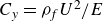 $C_y = \rho _{\kern-1pt f} U^{2}/E$
, where
$C_y = \rho _{\kern-1pt f} U^{2}/E$
, where $E$
is the Young’s modulus of the structure (i.e. Gosselin et al. Reference Gosselin, de Langre and Machado-Almeida2010; Gosselin & de Langre Reference Gosselin and de Langre2011; Lamoureux et al. Reference Lamoureux, Fillion, Ramananarivo, Gosselin and Melancon2025a
,
Reference Lamoureux, Ramananarivo, Melancon and Gosselinb
) or its variations, such as the dimensionless velocity that represents the ratio of the fluid inertia force and the bending force (i.e. Alben, Shelley & Zhang Reference Alben, Shelley and Zhang2002; Kim et al. Reference Kim, Cossé, Cerdeira and Gharib2013; Jung, Song & Kim Reference Jung, Song and Kim2021; Lee et al. Reference Lee, Kim and Kim2022, Reference Lee, Jung, Lee and Kim2023).
$E$
is the Young’s modulus of the structure (i.e. Gosselin et al. Reference Gosselin, de Langre and Machado-Almeida2010; Gosselin & de Langre Reference Gosselin and de Langre2011; Lamoureux et al. Reference Lamoureux, Fillion, Ramananarivo, Gosselin and Melancon2025a
,
Reference Lamoureux, Ramananarivo, Melancon and Gosselinb
) or its variations, such as the dimensionless velocity that represents the ratio of the fluid inertia force and the bending force (i.e. Alben, Shelley & Zhang Reference Alben, Shelley and Zhang2002; Kim et al. Reference Kim, Cossé, Cerdeira and Gharib2013; Jung, Song & Kim Reference Jung, Song and Kim2021; Lee et al. Reference Lee, Kim and Kim2022, Reference Lee, Jung, Lee and Kim2023).
However, at low Reynolds number, the viscous force dominates over the inertial force, and the scaling of the fluid force should be appropriately modified. For our kirigami sheet in the low-Reynolds-number regime, the holes within the sheet are hydrodynamically blocked and the flow distribution is similar to that of the solid shell model with the same diameter $D$
; see figures 3(a) and 4(a). Thus, rather than the internal hole size or the cutting line spacing
$D$
; see figures 3(a) and 4(a). Thus, rather than the internal hole size or the cutting line spacing $d$
, the diameter of the sheet,
$d$
, the diameter of the sheet, $D$
, is a more appropriate length when scaling the viscous stress acting on it at low Reynolds number;
$D$
, is a more appropriate length when scaling the viscous stress acting on it at low Reynolds number; $\tau \sim \mu U / D$
. To scale the viscous fluid force acting on the kirigami sheet, it is necessary to determine the effective area. Although the deformed kirigami sheet is not flat, the projected frontal area can be used to represent the effective area, without considering the porosity of the sheet, because the holes within the sheet are blocked hydrodynamically. Although the holes are not completely blocked, porosity is neglected in calculating the effective area, regardless of the degree of structural deformation. The effective area
$\tau \sim \mu U / D$
. To scale the viscous fluid force acting on the kirigami sheet, it is necessary to determine the effective area. Although the deformed kirigami sheet is not flat, the projected frontal area can be used to represent the effective area, without considering the porosity of the sheet, because the holes within the sheet are blocked hydrodynamically. Although the holes are not completely blocked, porosity is neglected in calculating the effective area, regardless of the degree of structural deformation. The effective area $A_{\textit{eff}}$
then scales as
$A_{\textit{eff}}$
then scales as $D^{2}$
without considering porosity, and the viscous fluid force scales as
$D^{2}$
without considering porosity, and the viscous fluid force scales as
 \begin{align} F_{\kern-1pt f} \sim \mu \textit{UD}. \end{align}
The viscous fluid force should be balanced by the bending force of the kirigami sheet. For kirigami structures, the presence of cutting lines introduces geometric discontinuity that reduces the effective bending stiffness $B_{\textit{eff}}$
. Hence, the scaling of the bending force must account for the cutting ratio. Although the detailed geometry of the kirigami sheet may vary, the previous study on the interaction of fluids and kirigami structures introduced geometric parameters to capture variations in the effective bending stiffness arising from the cutting pattern (Marzin et al. Reference Marzin, Le Hay, de Langre and Ramananarivo2022). As described in § 2, the kirigami sheet was designed using a single design parameter, cutting ratio
$B_{\textit{eff}}$
. Hence, the scaling of the bending force must account for the cutting ratio. Although the detailed geometry of the kirigami sheet may vary, the previous study on the interaction of fluids and kirigami structures introduced geometric parameters to capture variations in the effective bending stiffness arising from the cutting pattern (Marzin et al. Reference Marzin, Le Hay, de Langre and Ramananarivo2022). As described in § 2, the kirigami sheet was designed using a single design parameter, cutting ratio $\gamma$
. However, in general, multiple parameters may be employed in the design of a circular kirigami sheet (Lamoureux et al. Reference Lamoureux, Fillion, Ramananarivo, Gosselin and Melancon2025a
). In addition to the cutting ratio
$\gamma$
. However, in general, multiple parameters may be employed in the design of a circular kirigami sheet (Lamoureux et al. Reference Lamoureux, Fillion, Ramananarivo, Gosselin and Melancon2025a
). In addition to the cutting ratio $\gamma$
, one may consider the number of sectors
$\gamma$
, one may consider the number of sectors $N$
, by which the circular sheet is divided into unit segments, and the distance between adjacent cutting lines
$N$
, by which the circular sheet is divided into unit segments, and the distance between adjacent cutting lines $d$
, which is normalised by the sheet diameter
$d$
, which is normalised by the sheet diameter $D$
(distance ratio
$D$
(distance ratio $d^{*} = d/D$
).
$d^{*} = d/D$
).
In the present study, we assume that the effective bending stiffness $B_{\textit{eff}}=B_{\textit{eff}}(E, h, \gamma , N, d^{*})$
can be expressed as the product of the bending stiffness of a flat circular sheet (uncut sheet) and an empirical function
$B_{\textit{eff}}=B_{\textit{eff}}(E, h, \gamma , N, d^{*})$
can be expressed as the product of the bending stiffness of a flat circular sheet (uncut sheet) and an empirical function $f(\gamma , N, d^{*})$
, where
$f(\gamma , N, d^{*})$
, where $\gamma$
,
$\gamma$
, $N$
and
$N$
and $d^{*}$
denote the cutting ratio, number of sectors and distance ratio, respectively. The bending force then scales as
$d^{*}$
denote the cutting ratio, number of sectors and distance ratio, respectively. The bending force then scales as $F_{b} \sim f(\gamma , N, d^{*}) E h^{3}/D$
. Based on mechanical loading tests of circular kirigami sheets reported by Tani et al. (Reference Tani, Hong, Tomizawa, Lepoivre, Bico and Roman2024), the relationship between point loading and the resulting deflection was examined for our model, and an empirical function of the form
$F_{b} \sim f(\gamma , N, d^{*}) E h^{3}/D$
. Based on mechanical loading tests of circular kirigami sheets reported by Tani et al. (Reference Tani, Hong, Tomizawa, Lepoivre, Bico and Roman2024), the relationship between point loading and the resulting deflection was examined for our model, and an empirical function of the form $f(\gamma , N, d^{*}) = C N^4 d^{*2} / \gamma$
was derived, where
$f(\gamma , N, d^{*}) = C N^4 d^{*2} / \gamma$
was derived, where $C$
is a proportionality constant; see Appendix A for the details of the empirical function. Substituting this relation into the scaling of the bending force yields
$C$
is a proportionality constant; see Appendix A for the details of the empirical function. Substituting this relation into the scaling of the bending force yields
 \begin{align} F_{b} \sim Eh^3 N^4 d^{*2} /\gamma D. \end{align}
From the ratio of the viscous fluid force (3.2) to the bending force (3.3), the dimensionless velocity $U^*$
is given as
$U^*$
is given as
 \begin{align} U^{*} =\mu \textit{UD}^{2} \gamma / E h ^{3} N^{4} d^{*2}. \end{align}
This dimensionless velocity has a form similar to that of the dimensionless parameters proposed in prior studies on the flow-induced deformation of an elastic structure in a highly viscous flow (Pezzulla et al. Reference Pezzulla, Strong, Gallaire and Reis2020; Luna Lin et al. Reference Luna Lin, Pezzulla and Reis2023). The key distinction here is that the design parameters of the circular kirigami (cutting ratio, number of sectors, distance ratio) are explicitly embedded in the formulation.
We quantitatively analyse the quasi-static deformation of the kirigami sheet in the low-Reynolds-number regime. Although the actual deformation of the sheet is geometrically complex, the deformed surface can be simply approximated as the surface of a truncated cone owing to the axisymmetry of the deformed surface. The surface of a truncated cone is represented by the variables shown in figure 7. The displacement of the sheet in the direction opposite to the translation motion, relative to the rigid frame, is defined as $\delta$
, which corresponds to the height of the truncated cone. For a given kirigami sheet design, the magnitude of the streamwise deflection
$\delta$
, which corresponds to the height of the truncated cone. For a given kirigami sheet design, the magnitude of the streamwise deflection $\delta$
increases almost linearly with the translation speed
$\delta$
increases almost linearly with the translation speed $U$
(figure 8). This result matches the scaling of the viscous fluid force,
$U$
(figure 8). This result matches the scaling of the viscous fluid force, $F_{\kern-1pt f} \sim \mu \textit{UD}$
(3.2), where the imposed fluid force is proportional to the translation speed. For a given cutting ratio
$F_{\kern-1pt f} \sim \mu \textit{UD}$
(3.2), where the imposed fluid force is proportional to the translation speed. For a given cutting ratio $\gamma$
,
$\gamma$
, $\delta$
decreases as the sheet thickness
$\delta$
decreases as the sheet thickness $h$
increases because of the higher bending stiffness (figure 8
a). For a given
$h$
increases because of the higher bending stiffness (figure 8
a). For a given $h$
, the increase in
$h$
, the increase in $\gamma$
leads to a greater
$\gamma$
leads to a greater $\delta$
due to the reduction in the effective bending stiffness caused by the cutting lines (figure 8
b); note that the bending force scales inversely with the cutting ratio,
$\delta$
due to the reduction in the effective bending stiffness caused by the cutting lines (figure 8
b); note that the bending force scales inversely with the cutting ratio, $F_{b} \sim Eh^3 N^4 d^{*2}/\gamma D$
(3.3).
$F_{b} \sim Eh^3 N^4 d^{*2}/\gamma D$
(3.3).
(a) Raw image of the reconfigured kirigami sheet with diameter $D$
= 100 mm and (b) approximation of the kirigami sheet as a truncated cone.
$D$
= 100 mm and (b) approximation of the kirigami sheet as a truncated cone.

(a) Streamwise deflection $\delta$
versus translation speed
$\delta$
versus translation speed $U$
for (a) different sheet thicknesses
$U$
for (a) different sheet thicknesses $h$
and a fixed cutting ratio
$h$
and a fixed cutting ratio $\gamma$
= 8.0, and for (b) different
$\gamma$
= 8.0, and for (b) different $\gamma$
and a fixed
$\gamma$
and a fixed $h$
= 0.4 mm.
$h$
= 0.4 mm.

The undeformed reference area of the sheet is $S_0 = \pi D^2/4$
. After flow-induced reconfiguration, the lateral surface area of the truncated cone is expressed as
$S_0 = \pi D^2/4$
. After flow-induced reconfiguration, the lateral surface area of the truncated cone is expressed as $A_1 = \pi (D+a)[(D-a)^2/4 + \delta ^2]^{1/2}/2$
and its right surface area (truncated area) is given as
$A_1 = \pi (D+a)[(D-a)^2/4 + \delta ^2]^{1/2}/2$
and its right surface area (truncated area) is given as $A_2 = \pi a^2/4$
(figure 7). The total area of the deformed surface is
$A_2 = \pi a^2/4$
(figure 7). The total area of the deformed surface is $S = A_1 + A_2$
. The difference between the deformed and initial surface areas can be approximated as the total area of the holes formed on the deformed sheet:
$S = A_1 + A_2$
. The difference between the deformed and initial surface areas can be approximated as the total area of the holes formed on the deformed sheet: $G = S - S_0$
. The porosity
$G = S - S_0$
. The porosity $\phi$
of the sheet is then defined by normalising the hole area
$\phi$
of the sheet is then defined by normalising the hole area $G$
using the deformed surface area
$G$
using the deformed surface area $S$
:
$S$
: $\phi = G/S = 1 - S_0/S$
. Consequently, the porosity is obtained from the initial diameter
$\phi = G/S = 1 - S_0/S$
. Consequently, the porosity is obtained from the initial diameter $D$
and the variables
$D$
and the variables $\delta$
and
$\delta$
and $a$
describing the deformed shape:
$a$
describing the deformed shape:
 \begin{align} \phi = 1-\frac {D^2}{a^2 + (D+a)[(D-a)^2+4\delta ^2]^{1/2}}. \end{align}
In previous studies on fluid–structure interactions involving elastic porous structures, the porosity of the structure was defined using the geometric parameters of the initial undeformed configuration, and thus it was independent of flow conditions and the mechanical properties of the structure (Guttag et al. Reference Guttag, Karimi, Falcón and Reis2018; Jin et al. Reference Jin, Kim, Cheng, Barry and Chamorro2020; Lee et al. Reference Lee, Mahravan and Kim2024). Because the porous state did not change dramatically during the reconfiguration process, the porosity based on the initial geometry was sufficient. In contrast, for the kirigami sheet, the porosity of the initial geometry is zero and the porosity is dependent on the reconfiguration.
To examine the combined effects of the flow conditions and effective bending stiffness on the streamwise deflection and porosity, the dimensionless velocity $U^*$
introduced in (3.4) is employed. This dimensionless parameter incorporates all key variables (
$U^*$
introduced in (3.4) is employed. This dimensionless parameter incorporates all key variables ( $\mu , U, D, \gamma , N, d, E, h$
) that determine the reconfiguration. When the normalised streamwise deflection
$\mu , U, D, \gamma , N, d, E, h$
) that determine the reconfiguration. When the normalised streamwise deflection $\delta /D$
(figure 9
a) and the reconfiguration-dependent porosity
$\delta /D$
(figure 9
a) and the reconfiguration-dependent porosity $\phi$
(figure 9
b), which is calculated based on (3.5), are plotted with respect to
$\phi$
(figure 9
b), which is calculated based on (3.5), are plotted with respect to $U^{*}$
, the data obtained from all the combinations of
$U^{*}$
, the data obtained from all the combinations of $U$
,
$U$
, $h$
and
$h$
and $\gamma$
considered in this study tend to collapse onto a single curve. When
$\gamma$
considered in this study tend to collapse onto a single curve. When $U^*$
is low (
$U^*$
is low ( $U^*\lt 110$
),
$U^*\lt 110$
), $\delta /D$
and
$\delta /D$
and $\phi$
increase almost linearly with
$\phi$
increase almost linearly with $U^*$
, but the slopes of
$U^*$
, but the slopes of $\delta /D$
and
$\delta /D$
and $\phi$
begin to decline near
$\phi$
begin to decline near $U^{*} = 110$
, having a saturated value of roughly
$U^{*} = 110$
, having a saturated value of roughly $\phi = 0.45$
beyond
$\phi = 0.45$
beyond $U^{*} = 310$
.
$U^{*} = 310$
.
(a) Normalised streamwise deflection $\delta /D$
and (b) reconfiguration-dependent porosity
$\delta /D$
and (b) reconfiguration-dependent porosity $\phi$
versus dimensionless velocity
$\phi$
versus dimensionless velocity $U^*$
.
$U^*$
.

The data in figure 9 do not perfectly collapse onto a single curve. This result can be explained from two perspectives. First, there is a limitation of the function $f(\gamma ,N,d^*)$
. This function is empirically determined from deflection measurements under a point load applied at the centre of the kirigami sheet. However, the kirigami sheet experiences fluid force over its entire surface, including the central region, so the function may not fully account for distributed hydrodynamic loading. Second, the simple force scaling described earlier is fundamentally based on the assumption that the structural deformation is sufficiently small; i.e. the system has a linear response. However, the deformation of the kirigami sheet can be large and highly nonlinear. Once
$f(\gamma ,N,d^*)$
. This function is empirically determined from deflection measurements under a point load applied at the centre of the kirigami sheet. However, the kirigami sheet experiences fluid force over its entire surface, including the central region, so the function may not fully account for distributed hydrodynamic loading. Second, the simple force scaling described earlier is fundamentally based on the assumption that the structural deformation is sufficiently small; i.e. the system has a linear response. However, the deformation of the kirigami sheet can be large and highly nonlinear. Once $U^{*}$
exceeds a certain threshold, the data exhibit deviations due to this nonlinearity. Here, linear and nonlinear responses are simply from the kinematic standpoint based on deflection and porosity, rather than a fluid-dynamic standpoint. For all cases considered in this study, the flow is not in the linear Stokes regime and fluid force is not proportional to translation speed
$U^{*}$
exceeds a certain threshold, the data exhibit deviations due to this nonlinearity. Here, linear and nonlinear responses are simply from the kinematic standpoint based on deflection and porosity, rather than a fluid-dynamic standpoint. For all cases considered in this study, the flow is not in the linear Stokes regime and fluid force is not proportional to translation speed $U$
.
$U$
.
In figure 9, the number of sectors, $N$
, and the distance ratio,
$N$
, and the distance ratio, $d^{*}$
, are fixed at
$d^{*}$
, are fixed at $N=4$
and
$N=4$
and $d^{*}=0.05$
, respectively. Therefore, it cannot be verified from the figure that the dimensionless velocity
$d^{*}=0.05$
, respectively. Therefore, it cannot be verified from the figure that the dimensionless velocity $U^*$
successfully characterises the changes in the sheet kinematics when
$U^*$
successfully characterises the changes in the sheet kinematics when $N$
and
$N$
and $d^*$
vary. To resolve this issue, we fabricated additional kirigami sheets and performed supplementary experiments to obtain the data of
$d^*$
vary. To resolve this issue, we fabricated additional kirigami sheets and performed supplementary experiments to obtain the data of $\delta /D$
and
$\delta /D$
and $\phi$
for different values of
$\phi$
for different values of $N$
and
$N$
and $d^*$
. These additional data match well with the original data of figure 9 in the small-deflection regime, although some deviations exist in the large-deflection regime; see figure 13 and Appendix B for details.
$d^*$
. These additional data match well with the original data of figure 9 in the small-deflection regime, although some deviations exist in the large-deflection regime; see figure 13 and Appendix B for details.
Instead of $U^*$
based on the viscous fluid force, we may consider an alternative dimensionless parameter based on the inertial fluid force that scales with dynamic pressure,
$U^*$
based on the viscous fluid force, we may consider an alternative dimensionless parameter based on the inertial fluid force that scales with dynamic pressure, $F_{\kern-1pt f} \sim \rho _{\kern-1pt f}U^2D^2$
, commonly adopted for the fluid force scaling in the high-Reynolds-number regime (Kim et al. Reference Kim, Cossé, Cerdeira and Gharib2013; Jung et al. Reference Jung, Song and Kim2021; Lee et al. Reference Lee, Jung, Lee and Kim2023). However, compared with
$F_{\kern-1pt f} \sim \rho _{\kern-1pt f}U^2D^2$
, commonly adopted for the fluid force scaling in the high-Reynolds-number regime (Kim et al. Reference Kim, Cossé, Cerdeira and Gharib2013; Jung et al. Reference Jung, Song and Kim2021; Lee et al. Reference Lee, Jung, Lee and Kim2023). However, compared with $U^*$
, this alternative dimensionless parameter is not suitable for characterising
$U^*$
, this alternative dimensionless parameter is not suitable for characterising $\delta /D$
and
$\delta /D$
and $\phi$
; see Appendix C for details.
$\phi$
; see Appendix C for details.
3.3. Drag force
The hydrodynamic blockage discussed in § 3.1 dramatically influences the drag force imposed on the reconfigured kirigami sheet in the quasi-steady state. The dimensional drag of the kirigami sheet, $F_{\textit{kirigami}}$
, is plotted with respect to the translation speed
$F_{\textit{kirigami}}$
, is plotted with respect to the translation speed $U$
for four sheet thicknesses
$U$
for four sheet thicknesses $h$
and two cutting ratios
$h$
and two cutting ratios $\gamma$
in figure 10. The drag force acting on a flat rigid disk representing the undeformed configuration is also included (black dashed lines in figure 10); the diameter of the flat rigid disk is identical to that of the kirigami sheet. For each case, the drag averaged over three trials is presented. In the low-Reynolds-number regime
$\gamma$
in figure 10. The drag force acting on a flat rigid disk representing the undeformed configuration is also included (black dashed lines in figure 10); the diameter of the flat rigid disk is identical to that of the kirigami sheet. For each case, the drag averaged over three trials is presented. In the low-Reynolds-number regime $ \textit{Re}_{D}$
= 4–15 (using glycerine), the drag force of the reconfigured kirigami sheet is comparable to that of the undeformed flat disk, regardless of
$ \textit{Re}_{D}$
= 4–15 (using glycerine), the drag force of the reconfigured kirigami sheet is comparable to that of the undeformed flat disk, regardless of $h$
and
$h$
and $\gamma$
(figure 10
a). Interestingly, a considerable portion of the data points lie above the black dashed line, indicating that, despite the formation of holes, the drag force increases as a result of flow-induced reconfiguration. In contrast, in the high-Reynolds-number regime
$\gamma$
(figure 10
a). Interestingly, a considerable portion of the data points lie above the black dashed line, indicating that, despite the formation of holes, the drag force increases as a result of flow-induced reconfiguration. In contrast, in the high-Reynolds-number regime $ \textit{Re}_{D}$
= 5000–20 000 (using water), the drag force of the reconfigured kirigami sheet is clearly less than that of the flat rigid disk (figure 10
b). This reduction is obviously attributed to hole formation in the kirigami sheet and significant flow permeation through the holes.
$ \textit{Re}_{D}$
= 5000–20 000 (using water), the drag force of the reconfigured kirigami sheet is clearly less than that of the flat rigid disk (figure 10
b). This reduction is obviously attributed to hole formation in the kirigami sheet and significant flow permeation through the holes.
Drag force acting on the kirigami sheet, $F_{\textit{kirigami}}$
, with respect to translation speed
$F_{\textit{kirigami}}$
, with respect to translation speed $U$
: (a) low-Reynolds-number regime (
$U$
: (a) low-Reynolds-number regime ( $ \textit{Re}_{D}$
= 4–15) and (b) high-Reynolds-number regime (
$ \textit{Re}_{D}$
= 4–15) and (b) high-Reynolds-number regime ( $ \textit{Re}_{D}$
= 5000–20 000). Panels (i) and (ii) present the results of a low cutting ratio
$ \textit{Re}_{D}$
= 5000–20 000). Panels (i) and (ii) present the results of a low cutting ratio $\gamma = 2.6$
and a high cutting ratio
$\gamma = 2.6$
and a high cutting ratio $\gamma = 8.0$
, respectively. The black dashed lines denote the drag force acting on the flat rigid disk. The schematic inside the panel shows the unit structure corresponding to the cutting ratio
$\gamma = 8.0$
, respectively. The black dashed lines denote the drag force acting on the flat rigid disk. The schematic inside the panel shows the unit structure corresponding to the cutting ratio $\gamma$
of each model.
$\gamma$
of each model.

The drag of the kirigami sheet in the low-Reynolds-number regime exhibits non-intuitive behaviour with respect to the cutting ratio $\gamma$
and sheet thickness
$\gamma$
and sheet thickness $h$
. For instance, for a sheet with a thickness of
$h$
. For instance, for a sheet with a thickness of $h = 0.6$
mm, the drag is larger than that of a flat rigid disk at
$h = 0.6$
mm, the drag is larger than that of a flat rigid disk at $\gamma = 2.6$
(figure 10
ai), but becomes smaller at
$\gamma = 2.6$
(figure 10
ai), but becomes smaller at $\gamma = 8.0$
(figure 10
aii). Interestingly, this trend is reversed for a sheet with a thickness of
$\gamma = 8.0$
(figure 10
aii). Interestingly, this trend is reversed for a sheet with a thickness of $h = 0.4$
mm. These opposing results do not appear in the high-Reynolds-number regime, where the lower
$h = 0.4$
mm. These opposing results do not appear in the high-Reynolds-number regime, where the lower $h$
generally results in the smaller drag at each
$h$
generally results in the smaller drag at each $\gamma$
(figure 10
bi, bii). At high Reynolds number, a thinner sheet undergoes greater deformation, which consequently forms larger holes. Because the fluid readily passes through these holes, the relationship between the drag and the sheet thickness is straightforward. However, at low Reynolds number, the drag is governed by a strong coupling between the structural reconfiguration and the hydrodynamic blockage. Because both
$\gamma$
(figure 10
bi, bii). At high Reynolds number, a thinner sheet undergoes greater deformation, which consequently forms larger holes. Because the fluid readily passes through these holes, the relationship between the drag and the sheet thickness is straightforward. However, at low Reynolds number, the drag is governed by a strong coupling between the structural reconfiguration and the hydrodynamic blockage. Because both $h$
and
$h$
and $\gamma$
are key design parameters determining the reconfiguration and hydrodynamic blockage, their effects on the drag are intertwined, making it difficult to isolate the influence of a single parameter.
$\gamma$
are key design parameters determining the reconfiguration and hydrodynamic blockage, their effects on the drag are intertwined, making it difficult to isolate the influence of a single parameter.
Drag ratio $F_{{kirigami}} / F_{\textit{disk}}$
with respect to dimensionless velocity
$F_{{kirigami}} / F_{\textit{disk}}$
with respect to dimensionless velocity $U^{*}$
in the low-Reynolds-number regime (
$U^{*}$
in the low-Reynolds-number regime ( $ \textit{Re}_{D}$
= 4–15).
$ \textit{Re}_{D}$
= 4–15).

In the low-Reynolds-number regime, the majority of drag ratio data $F_{\textit{kirigami}} / F_{\textit{disk}}$
cluster around unity in the broad range of
$F_{\textit{kirigami}} / F_{\textit{disk}}$
cluster around unity in the broad range of $U^{*}$
considered in this study (figure 11);
$U^{*}$
considered in this study (figure 11); $F_{\textit{disk}}$
is the drag acting on the flat rigid disk. The drag ratio is actually similar to the reconfiguration number, commonly used to quantify how reconfiguration affects drag force in general elastic structures (Gosselin et al. Reference Gosselin, de Langre and Machado-Almeida2010; Gosselin & de Langre Reference Gosselin and de Langre2011; Satheesh & Huera-Huarte Reference Satheesh and Huera-Huarte2019; Song et al. Reference Song, Yoo, Ham and Kim2022; Lamoureux et al. Reference Lamoureux, Ramananarivo, Melancon and Gosselin2025b
). The drag force of the kirigami sheet does not significantly deviate from that of the flat rigid disk when significant structural deformation and hole formation occur, and the drag ratio can be greater than unity even under high
$F_{\textit{disk}}$
is the drag acting on the flat rigid disk. The drag ratio is actually similar to the reconfiguration number, commonly used to quantify how reconfiguration affects drag force in general elastic structures (Gosselin et al. Reference Gosselin, de Langre and Machado-Almeida2010; Gosselin & de Langre Reference Gosselin and de Langre2011; Satheesh & Huera-Huarte Reference Satheesh and Huera-Huarte2019; Song et al. Reference Song, Yoo, Ham and Kim2022; Lamoureux et al. Reference Lamoureux, Ramananarivo, Melancon and Gosselin2025b
). The drag force of the kirigami sheet does not significantly deviate from that of the flat rigid disk when significant structural deformation and hole formation occur, and the drag ratio can be greater than unity even under high $U^*$
. In contrast, the drag ratio is near 0.5 in most cases in the high-Reynolds-number regime, as can be seen in figure 10(b).
$U^*$
. In contrast, the drag ratio is near 0.5 in most cases in the high-Reynolds-number regime, as can be seen in figure 10(b).
When elastic structures such as sheets and fibres undergo reconfiguration under flow, the drag generally declines from that of their initial configuration. However, a few studies have reported the opposite effect. Under specific flow conditions and structure designs, the frontal area of the deforming structure can instead become greater after reconfiguration, enhancing the drag; for example, a model of multiple fibres attached to a central structure at high Reynolds number (Gosselin & de Langre Reference Gosselin and de Langre2011) and an array of elastically mounted cylinders under strong hydrodynamic blockage (Lee et al. Reference Lee, Mahravan and Kim2024). In the present study, the radial expansion of the outer edge of the kirigami sheet is constrained by the rigid frame, and the physical frontal area decreases due to hole formation. Nevertheless, the drag of the reconfigured kirigami sheet can exceed that of the flat rigid disk with the same diameter in many experimental cases of low Reynolds number, by virtue of strong hydrodynamic blockage.
Furthermore, to more clearly evaluate the blockage effect of the kirigami sheet, drag measurements were performed for the specific truncated-cone-shaped solid shell model described in figure 4, which corresponds to the large-deflection case ([ $U$
,
$U$
, $h$
,
$h$
, $\gamma$
] = [15 cm s
$\gamma$
] = [15 cm s $^{-1}$
, 0.3 mm, 8.0]). The kirigami sheet of the large-deflection case exhibits a drag ratio of
$^{-1}$
, 0.3 mm, 8.0]). The kirigami sheet of the large-deflection case exhibits a drag ratio of $F_{\textit{kirigami}} / F_{\textit{disk}} = 1.15$
despite the formation of large holes and the high porosity (
$F_{\textit{kirigami}} / F_{\textit{disk}} = 1.15$
despite the formation of large holes and the high porosity ( $\phi = 0.52$
). Although the kirigami sheet in the large-deflection case has a thickness of
$\phi = 0.52$
). Although the kirigami sheet in the large-deflection case has a thickness of $h = 0.3$
mm, the solid shell model could not be fabricated with the same thickness because the printed structure could not maintain its shape and failed due to the mechanical properties of the printer filament. Therefore, the shell was fabricated with a larger thickness of
$h = 0.3$
mm, the solid shell model could not be fabricated with the same thickness because the printed structure could not maintain its shape and failed due to the mechanical properties of the printer filament. Therefore, the shell was fabricated with a larger thickness of $h = 1.0$
mm to ensure structural integrity. The drag force acting on the solid shell model is 0.21 N. For reference, the drag force of the reconfigured kirigami sheet of the large-deflection case is 0.18 N. Although the hydrodynamic blockage is strong, it does not completely prevent flow through the holes, so the kirigami sheet produces slightly lower drag than the solid shell model. Nevertheless, it is notable that in the low-Reynolds-number regime, the reconfigured kirigami sheet can retain approximately 90 % of the drag generated by the corresponding solid shell model. Because of its many holes, the reconfigured kirigami sheet has a considerably lower mass than the corresponding solid shell model and can modulate its shape passively in response to external conditions. Along with these inherent advantages, the generation of comparable drag suggests that the kirigami sheet holds potential for future application to the design of small-scale drag-based transport and propulsion systems in viscosity-dominant environments.
$h = 1.0$
mm to ensure structural integrity. The drag force acting on the solid shell model is 0.21 N. For reference, the drag force of the reconfigured kirigami sheet of the large-deflection case is 0.18 N. Although the hydrodynamic blockage is strong, it does not completely prevent flow through the holes, so the kirigami sheet produces slightly lower drag than the solid shell model. Nevertheless, it is notable that in the low-Reynolds-number regime, the reconfigured kirigami sheet can retain approximately 90 % of the drag generated by the corresponding solid shell model. Because of its many holes, the reconfigured kirigami sheet has a considerably lower mass than the corresponding solid shell model and can modulate its shape passively in response to external conditions. Along with these inherent advantages, the generation of comparable drag suggests that the kirigami sheet holds potential for future application to the design of small-scale drag-based transport and propulsion systems in viscosity-dominant environments.
If a drag-based propulsion system is designed using a kirigami sheet, the sheet should move freely in response to the external flow. From this perspective, it is necessary to examine the stability of the kirigami sheet in the absence of any constraining parts such as the rigid frame. We conducted simple free-fall experiments under low-Reynolds-number conditions. A weight of mass was attached at the centre of the kirigami sheet, which was similar to the model of Lamoureux et al. (Reference Lamoureux, Fillion, Ramananarivo, Gosselin and Melancon2025a ), and the sheet was released in a vertical glass tank filled with glycerine. Depending on the bending stiffness of the sheet, the reconfigured shape differed markedly; however, the falling trajectory remained nearly vertical, indicating highly stable descent. These observations contrast with those from free-fall experiments performed in air (Lamoureux et al. Reference Lamoureux, Fillion, Ramananarivo, Gosselin and Melancon2025a ), in which a pronounced horizontal drift occurred during the descent of the kirigami sheet. Although the experimental model considered here is simple and idealised, these results suggest that systems designed with kirigami sheets may exhibit a high level of stability in viscosity-dominated environments.
4. Concluding remarks
In this study, we have investigated the flow-induced reconfiguration and drag of a kirigami sheet in the low-Reynolds-number regime. Flow visualisation revealed a clear contrast in flow distribution between the low- and high-Reynolds-number regimes. At high Reynolds number, the flow penetrates through the holes formed by the reconfigured kirigami sheet. In contrast, at low Reynolds number, a significant portion of the flow bypasses the sheet due to the hydrodynamic blockage imposed by strong viscous diffusion. The dimensionless velocity based on force scaling at quasi-static deformation effectively captures the trends in both the deflection and porosity of the kirigami sheet, even under pronounced deformation with a notable hole size. In the low-Reynolds-number regime, the reconfigured kirigami sheet can enhance drag compared with a flat rigid disk, providing quantitative evidence that the formation of virtual fluid barriers is crucial in determining the hydrodynamic performance of the kirigami sheet.
Although the present study has unravelled the novel features of a highly poroelastic structure in viscosity-dominant flow, a simple circular geometry and ideal flow conditions were used, along with a limited range of cutting patterns. Moreover, the analysis focused on quasi-static deformation, without considering fully unsteady or transient effects that may occur under more complex operating scenarios and external environments. To generalise the ideas proposed herein regarding reconfiguration under strong viscous diffusion, future work should explore diverse kirigami patterns and dynamic interactions with unsteady flows. Comprehensive analysis of the underlying low-Reynolds-number fluid–structure interaction will enable the aero- and hydrodynamic designs of efficient and morphable kirigami-based small-scale systems.
Funding
This research was supported by the National Research Foundation of Korea (NRF) grant funded by the Korea government (MSIT) (RS-2024-00355146) and the Challengeable Future Defense Technology Research and Development Program through the Agency for Defense Development (ADD) funded by the Defense Acquisition Program Administration (DAPA) (No.915143101)
Declaration of interests
The authors report no conflict of interest.
Appendix A. Relationship between effective bending stiffness and design parameters
To establish the relationship between the effective bending stiffness $B_{\textit{eff}}$
and geometric design parameters (
$B_{\textit{eff}}$
and geometric design parameters ( $\gamma$
,
$\gamma$
, $N$
and
$N$
and $d^{*}$
) of the kirigami sheet, we conducted point-load tests to measure the sheet deformation while systematically varying the design parameters, following the approach of Tani et al. (Reference Tani, Hong, Tomizawa, Lepoivre, Bico and Roman2024). The horizontal rigid frame was fixed without prescribed translation and a vertical point load
$d^{*}$
) of the kirigami sheet, we conducted point-load tests to measure the sheet deformation while systematically varying the design parameters, following the approach of Tani et al. (Reference Tani, Hong, Tomizawa, Lepoivre, Bico and Roman2024). The horizontal rigid frame was fixed without prescribed translation and a vertical point load $P$
was applied at the centre of the kirigami sheet (figure 12
a). The resulting deflection
$P$
was applied at the centre of the kirigami sheet (figure 12
a). The resulting deflection $\delta$
was measured as the downward displacement of the sheet at the loading point by varying the cutting ratio
$\delta$
was measured as the downward displacement of the sheet at the loading point by varying the cutting ratio $\gamma$
while fixing the other parameters at
$\gamma$
while fixing the other parameters at $N = 4$
and
$N = 4$
and $d^* = 0.05$
(figure 12
bi). When
$d^* = 0.05$
(figure 12
bi). When $\delta /\gamma$
is used instead of
$\delta /\gamma$
is used instead of $\delta$
, the data collapse onto a single curve (figure 12
ci). Similarly, for the given
$\delta$
, the data collapse onto a single curve (figure 12
ci). Similarly, for the given $\gamma = 5.0$
and
$\gamma = 5.0$
and $d^* = 0.05$
,
$d^* = 0.05$
, $\delta N^4$
is an appropriate variable to depict the deflection trend by the variations in
$\delta N^4$
is an appropriate variable to depict the deflection trend by the variations in $N$
(figure 12
bii, cii), and for the given
$N$
(figure 12
bii, cii), and for the given $\gamma = 5.0$
and
$\gamma = 5.0$
and $N =4$
,
$N =4$
, $\delta d^{*2}$
captures the deflection trend by the variations in
$\delta d^{*2}$
captures the deflection trend by the variations in $d^*$
(figure 12
biii, ciii). Accordingly, the geometric factor governing the effective bending stiffness can be expressed empirically as
$d^*$
(figure 12
biii, ciii). Accordingly, the geometric factor governing the effective bending stiffness can be expressed empirically as $f(\gamma , N, d^*) = C N^{4}d^{*2}/\gamma$
, where
$f(\gamma , N, d^*) = C N^{4}d^{*2}/\gamma$
, where $C$
is an empirically determined constant:
$C$
is an empirically determined constant: $B_{\textit{eff}} = f(\gamma , N, d^{*})Eh^3=(C N^{4}d^{*2}/\gamma )Eh^3$
.
$B_{\textit{eff}} = f(\gamma , N, d^{*})Eh^3=(C N^{4}d^{*2}/\gamma )Eh^3$
.
(a) Raw image of the point-load deformation test for the kirigami sheet with diameter $D$
= 100 mm ([
$D$
= 100 mm ([ $h$
,
$h$
, $\gamma$
,
$\gamma$
, $N$
,
$N$
, $d^*$
] = [0.5 mm, 2.6, 4, 0.05]) and point load
$d^*$
] = [0.5 mm, 2.6, 4, 0.05]) and point load $P$
= 0.049 N. (b) Vertical deflection
$P$
= 0.049 N. (b) Vertical deflection $\delta$
with respect to point load
$\delta$
with respect to point load $P$
for different values of each design variable; (i)
$P$
for different values of each design variable; (i) $\gamma$
, (ii)
$\gamma$
, (ii) $N$
and (iii)
$N$
and (iii) $d^*$
. (c) Vertical deflection rescaled as (i)
$d^*$
. (c) Vertical deflection rescaled as (i) $\delta /\gamma$
, (ii)
$\delta /\gamma$
, (ii) $\delta N^4$
and (iii)
$\delta N^4$
and (iii) $\delta d^{*2}$
from the corresponding plots of panels (bi)–(biii), respectively.
$\delta d^{*2}$
from the corresponding plots of panels (bi)–(biii), respectively.

Appendix B. Effects of additional design parameters on sheet deformation
To examine the effects of additional design parameters $N$
and
$N$
and $d^*$
on sheet deformation, supplementary experiments were conducted. In addition to
$d^*$
on sheet deformation, supplementary experiments were conducted. In addition to $N = 4$
,
$N = 4$
, $N$
= 3, 5 and 6 were considered while the other design parameters were fixed (
$N$
= 3, 5 and 6 were considered while the other design parameters were fixed ( $h$
= 0.5 mm,
$h$
= 0.5 mm, $\gamma =5.0$
,
$\gamma =5.0$
, $d^*$
= 0.05), and similarly
$d^*$
= 0.05), and similarly $d^*$
= 0.06, 0.07, 0.08 were considered in addition to
$d^*$
= 0.06, 0.07, 0.08 were considered in addition to $d^* = 0.05$
with the other design parameters unchanged (
$d^* = 0.05$
with the other design parameters unchanged ( $h$
= 0.5 mm,
$h$
= 0.5 mm, $\gamma =5.0$
,
$\gamma =5.0$
, $N$
= 4). The data of these supplementary cases are added to figure 9. Both the normalised streamwise deflection
$N$
= 4). The data of these supplementary cases are added to figure 9. Both the normalised streamwise deflection $\delta /D$
(figure 13
a) and the reconfiguration-dependent porosity
$\delta /D$
(figure 13
a) and the reconfiguration-dependent porosity $\phi$
(figure 13
b) match well with the original data in the small-deflection regime although some deviations exist in the large-deflection regime. It indicates that the dimensionless velocity
$\phi$
(figure 13
b) match well with the original data in the small-deflection regime although some deviations exist in the large-deflection regime. It indicates that the dimensionless velocity $U^{*}$
(3.4) appropriately captures the effects of not only the cutting ratio
$U^{*}$
(3.4) appropriately captures the effects of not only the cutting ratio $\gamma$
, but also the additional design parameters
$\gamma$
, but also the additional design parameters $N$
and
$N$
and $d^{*}$
.
$d^{*}$
.
Original and supplementary (black hexagram) deformation data: (a) normalised streamwise deflection $\delta /D$
and (b) reconfiguration-dependent porosity
$\delta /D$
and (b) reconfiguration-dependent porosity $\phi$
versus dimensionless velocity
$\phi$
versus dimensionless velocity $U^*$
.
$U^*$
.

Appendix C. Dimensionless velocity based on dynamic pressure
In the low-Reynolds-number regime, the pressure-induced drag generally accounts for a finite portion of the overall drag. However, in this study, the scaling of the fluid force with viscous stress characterises the deformation of the kirigami sheet more accurately. To confirm this, we introduce alternative dimensionless velocity $\hat {U}$
based on the fluid force that scales with dynamic pressure (
$\hat {U}$
based on the fluid force that scales with dynamic pressure (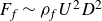 $F_{\kern-1pt f} \sim \rho _{\kern-1pt f}U^2D^2$
) and the bending force (
$F_{\kern-1pt f} \sim \rho _{\kern-1pt f}U^2D^2$
) and the bending force ( $F_{b} \sim Eh^3 N^4 d^{*2}/\gamma D$
):
$F_{b} \sim Eh^3 N^4 d^{*2}/\gamma D$
):
 \begin{align} \hat {U} = \big(\rho _{\kern-1pt f} U^2 D^{3} \gamma / E h ^{3} N^4 d^{*2} \big)^{1/2}. \end{align}
Figure 9 is replotted with respect to $\hat {U}$
in figure 14. Although the monotonic increasing trend is captured, the data scatter to a greater extent for both the streamwise deflection and porosity, compared with figure 9 with respect to
$\hat {U}$
in figure 14. Although the monotonic increasing trend is captured, the data scatter to a greater extent for both the streamwise deflection and porosity, compared with figure 9 with respect to $U^{*}$
.
$U^{*}$
.
(a) Normalised streamwise deflection $\delta /D$
and (b) reconfiguration-dependent porosity
$\delta /D$
and (b) reconfiguration-dependent porosity $\phi$
versus alternative dimensionless velocity
$\phi$
versus alternative dimensionless velocity $\hat {U}$
(C1).
$\hat {U}$
(C1).


 θc
θc θnc
θnc γ=2.6
γ=2.6 γ=8.0
γ=8.0
 D
D U
U U
U −1
−1 U
U −1
−1 U
U −1
−1 U
U −1
−1 h
h γ
γ
 x
x urel/U
 U
U h
h γ
γ −1
−1 ReD
ReD ReD
ReD
 x
x urel/U
 U
U h
h γ
γ −1
−1 ReD
ReD ReD
ReD
 y
y vrel/U
 ReD
ReD ReD
ReD U
U h
h γ
γ −1
−1 U
U h
h γ
γ −1
−1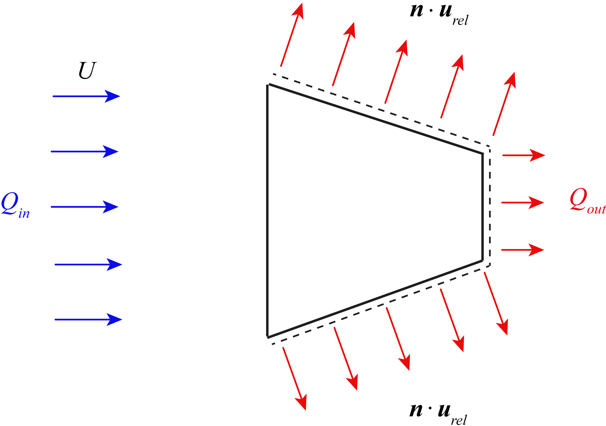
 Qin
Qin Qout
Qout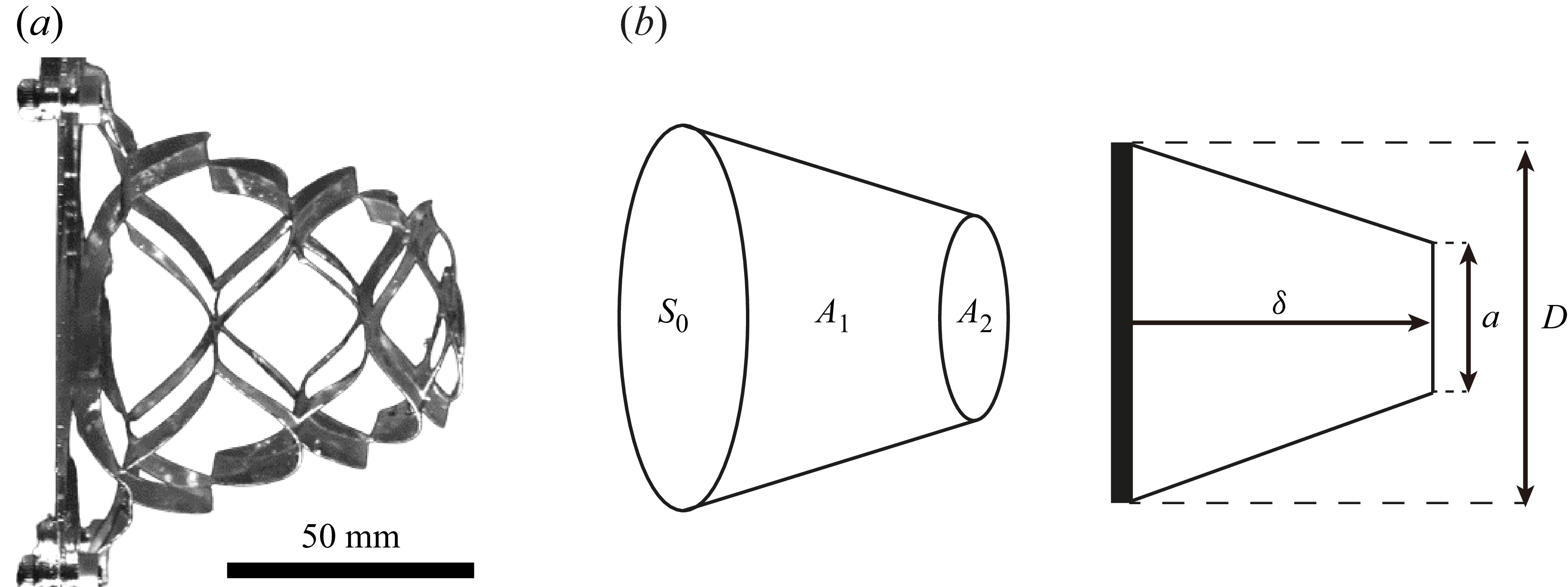
 D
D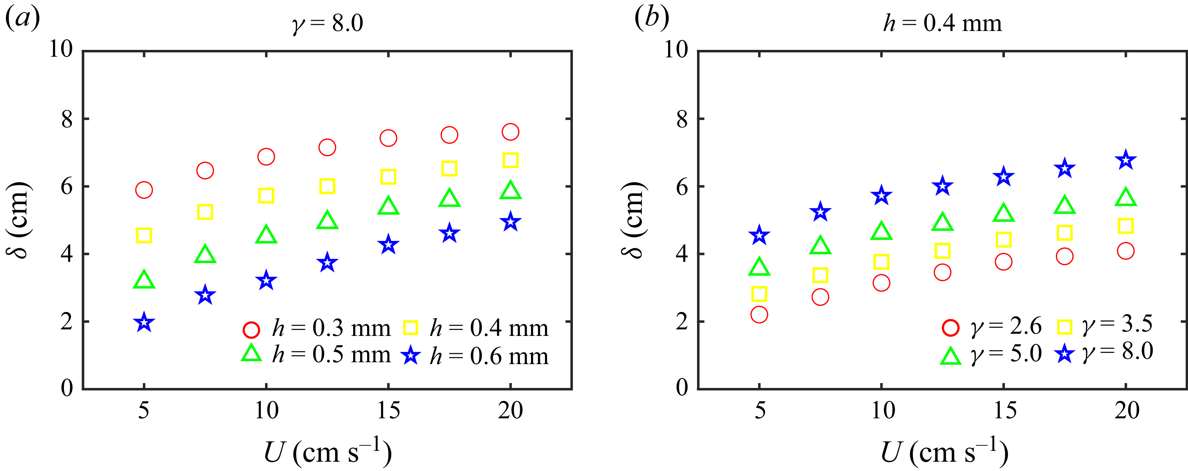
 δ
δ U
U h
h γ
γ γ
γ h
h
 δ/D
δ/D ϕ
ϕ U∗
U∗
 Fkirigami
 U
U ReD
ReD ReD
ReD γ=2.6
γ=2.6 γ=8.0
γ=8.0 γ
γ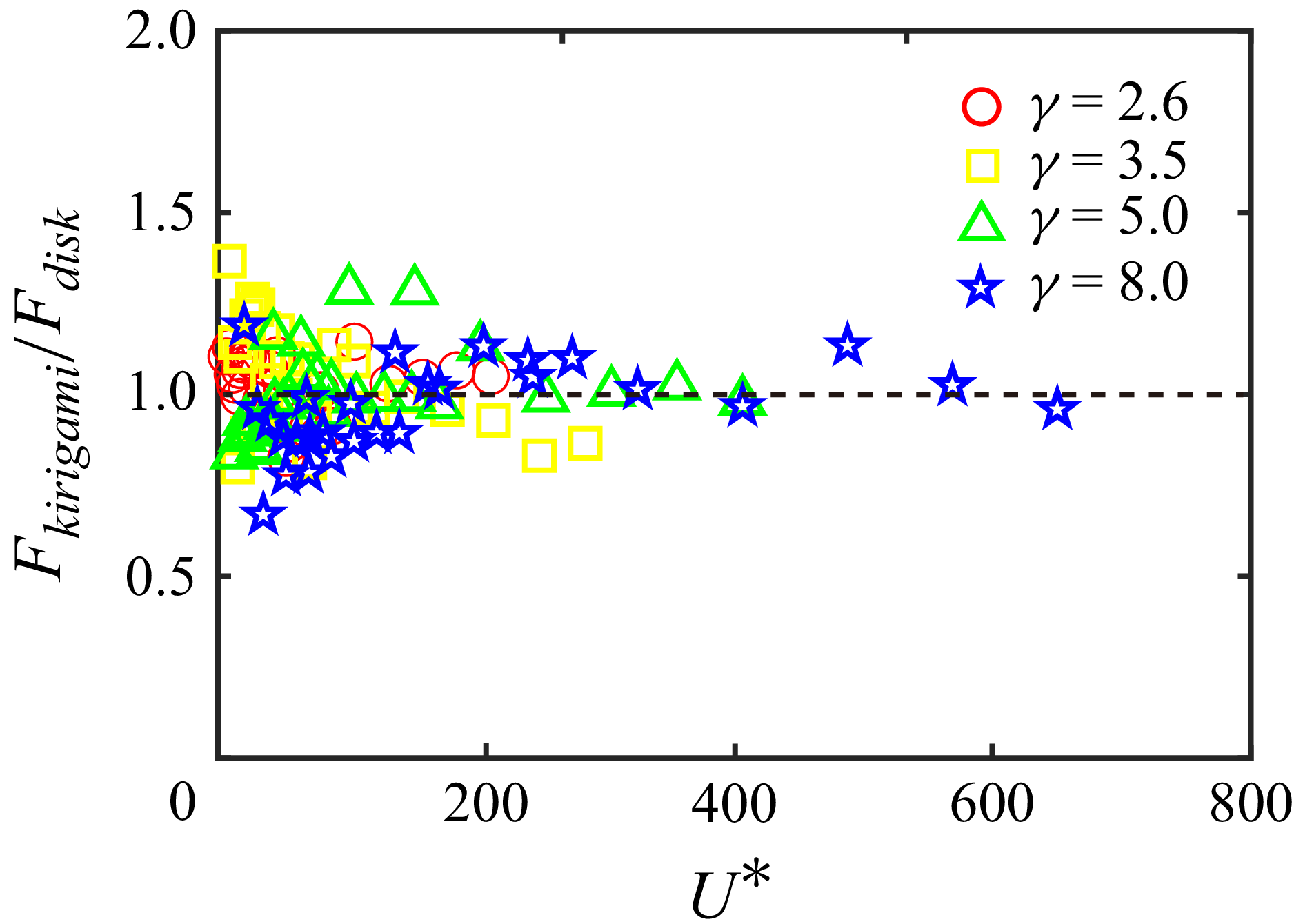
 Fkirigami/Fdisk
 U∗
U∗ ReD
ReD
 D
D h
h γ
γ N
N d∗
d∗ P
P δ
δ P
P γ
γ N
N d∗
d∗ δ/γ
δ/γ δN4
δN4 δd∗2
δd∗2
 δ/D
δ/D ϕ
ϕ U∗
U∗
 δ/D
δ/D ϕ
ϕ U^
U^
 Open access

