


1 Introduction
Since the invention of lasers in 1960[ Reference Maiman 1 ], laser peak power has been increased continuously in two ways: by reducing the pulse duration through methods such as Q-switching, mode-locking and pulse compression, and increasing pulse energy through laser amplification. However, the laser peak power has stagnated due to the laser crystal damage problem during the amplification of ultrashort laser pulses. With the invention of chirped pulse amplification (CPA)[ Reference Strickland and Mourou 2 ] and optical parametric chirped pulse amplification (OPCPA)[ Reference Dubietis, Jonusauskas and Piskarskas 3 ], the laser peak power has continually increased again since 1985. Currently, two 10-petawatt (PW) lasers are already in operation at SULF (China) and ELI-NP (Europe)[ Reference Danson, White, Barr, Bett, Blyth, Bowley, Brenner, Collins, Croxford, Dangor, Devereux, Dyer, Dymoke-Bradshaw, Edwards, Ewart, Ferguson, Girkin, Hall, Hanna, Harris, Hillier, Hooker, Hooker, Hopps, Hull, Hunt, Jaroszynski, Kempenaars, Kessler, Knight, Knight, Knowles, Lewis, Lipton, Littlechild, Littlechild, Maggs, Malcolm, Mangles, Martin, McKenna, Moore, Morrison, Najmudin, Neely, New, Norman, Paine, Parker, Penman, Pert, Pietraszewski, Randewich, Rizvi, Seddon, Sheng, Slater, Smith, Spindloe, Taylor, Thomas, Tisch, Wark, Webb, Wiggins, Willford and Winstone 4 – Reference Zhang, Wu, Hu, Yang, Gui, Ji, Liu, Wang, Liu, Lu, Xu, Leng, Li and Xu 7 ]. According to a recent review, nearly 50 laser facilities with PW-level peak power exist worldwide[ Reference Danson, Haefner, Bromage, Butcher, Chanteloup, Chowdhury, Galvanauskas, Gizzi, Hein, Hillier, Hopps, Kato, Khazanov, Kodama, Korn, Li, Li, Limpert, Ma, Nam, Neely, Papadopoulos, Penman, Qian, Rocca, Shaykin, Siders, Spindloe, Szatmári, Trines, Zhu, Zhu and Zuegel 8 ]. Moreover, severalinstitutions in Europe, the USA, Russia, Japan and China have reported ambitious plans to achieve 10s–100s PW lasers based on OPCPA: ELI-200PW (Europe), EP-OPAL-75PW (USA), XCELS-200PW (Russia), GEKKO-EXA-50PW (Japan) and SEL-100PW (China). The focused intensities of these lasers are expected to be higher than 1023 W/cm2 [ Reference Danson, Haefner, Bromage, Butcher, Chanteloup, Chowdhury, Galvanauskas, Gizzi, Hein, Hillier, Hopps, Kato, Khazanov, Kodama, Korn, Li, Li, Limpert, Ma, Nam, Neely, Papadopoulos, Penman, Qian, Rocca, Shaykin, Siders, Spindloe, Szatmári, Trines, Zhu, Zhu and Zuegel 8 ]. This ultrahigh peak-power laser can push the fundamental light–electron interaction to quantum electrodynamics; facilitate nuclear quantum optics; and potentially lead to the discovery of new particles beyond the standard model[ Reference Di Piazza, Muller, Hatsagortsyan and Keitel 9 ].
For all planned 10s–100s PW laser facilities, the main problem is the absence of compression gratings with a sufficiently high damage threshold and large enough size, where the last grating withstanding the shortest pulse duration is the fuse of the grating-based compressor. As a result, phase-locking of multiple channels of 10-PW lasers is a starting solution to achieve 100s PW for XCELS-200PW, ELI-200PW and SEL-100PW[ Reference Danson, Haefner, Bromage, Butcher, Chanteloup, Chowdhury, Galvanauskas, Gizzi, Hein, Hillier, Hopps, Kato, Khazanov, Kodama, Korn, Li, Li, Limpert, Ma, Nam, Neely, Papadopoulos, Penman, Qian, Rocca, Shaykin, Siders, Spindloe, Szatmári, Trines, Zhu, Zhu and Zuegel 8 ]. However, this phase-locking is very sensitive to many laser parameters across the laser channels, such as the optical delay, pointing stability, beam wavefront and spectral chirp[ Reference Wang and Leng 10 ]. A method called the multistep pulse compressor (MPC) has been proposed recently to solve the compression problem. In this method, the pulse-energy-limitation problem in the grating-based compressor is transferred to the spatiotemporal properties of the input/output laser beams[ Reference Liu, Shen, Du and Li 11 ]. As an improvement of the typical MPC, a multistage-smoothing MPC (MS-MPC) based on an asymmetric four-grating compressor (AFGC) was also proposed to achieve ultrahigh peak-power output and safe operation simultaneously[ Reference Shen, Du, Liang, Wang, Liu and Li 12 , Reference Du, Shen, Liang, Wang, Liu and Li 13 ].
In this study, the MPC method is further improved based on a single-pass single-grating-pair (SSGP) main compressor. In comparison to the AFGC main compressor, only two parallel gratings with relatively long perpendicular distance are used to generate the same amount of spectral chirp in the main compressor. Furthermore, the grating pair can induce the largest spatial chirp compared to the AFGC, which can achieve the best beam-smoothing effect. Besides saving compared with two expensive gratings, the total compression efficiency of the SSGP compressor is even larger than that of the AFGC because there are only two gratings to induce diffraction loss. Moreover, the wavefront distortion of the gratings at the central wavelength can be compensated directly by using deformable mirrors in the proposed SSGP-based MPC design. However, the wavefront distortion cannot be compensated effectively inside a four-grating main compressor[ Reference Li and Miyanaga 14 – Reference Pariente, Gallet, Borot, Gobert and Quéré 16 ], which will reduce the final focused intensity seriously.
2 Single-pass single-grating-pair-based main compressor
2.1 Optical scheme
In the previous work[ Reference Du, Shen, Liang, Wang, Liu and Li 13 ], an AFGC was used as the main compressor to compensate for the spectral chirp and induce a suitably small spatial chirp to smooth the laser beam simultaneously. This is because an AFGC is equal to a symmetric four-grating compressor and an SSGP compressor with a short grating-pair distance. In fact, only the equivalent SSGP compressor induces spatial chirp. The distance difference can be increased between the two grating pairs, L 2 –L 1 in Figure 1(a), to introduce the maximum spatial chirp width, which is limited by the optical block between the grating pair.
Optical schemes of the (a) AFGC and (b) SSGP compressor. G1–G4 are diffraction gratings; L = L 1 + L 2. In the four beam profiles, the dark gray areas contain full spectra, and the red and blue areas contain partial longer and shorter spectra, respectively.

The optical schemes of the AFGC and SSGP compressor are shown in Figures 1(a) and 1(b), respectively. The two compressors can induce the same amounts of spectral chirp but different amounts of spatial chirp. The induced spatial chirp ratio between the AFGC and SSGP compressor is (L
2–L
1) / L, where $L=L_1+L_2$
for an identical input chirped pulse.
$L=L_1+L_2$
for an identical input chirped pulse.
In a grating-pair-based pulse compressor[ Reference Treacy 17 ], the induced phase shift can be expressed as follows:
 $$ \begin{align}\varPhi \left(\omega \right)=\omega {L}_0\left[1+\cos \left({\theta}_\mathrm{r}-{\theta}_\mathrm{i}\right)\right]\sec \left({\theta}_\mathrm{r}\right)/c,\end{align}$$
where ω is the laser frequency, L
0 is the perpendicular distance of the grating pair and θ
r and θ
i are the diffraction angle and the incident angle, respectively. The induced spectral chirps are the Taylor coefficients of $\varPhi$
(ω), all linearly related to L
0. For example, the second-order phase dispersion can be expressed as follows:
$\varPhi$
(ω), all linearly related to L
0. For example, the second-order phase dispersion can be expressed as follows:
 $$\begin{align}{\varPhi}_2=-8\pi 2{cL}_\mathrm{g}/\left[{\omega_0}^3{d}^2{\cos}^2\left({\theta}_{\mathrm{r}0}\right)\right],\end{align}$$
where L g = L 0sec(θ r0) is the central distance of the two parallel gratings, d is the grating groove density and ω 0 and θr 0 are the laser frequency and diffraction angle at the central wavelength, respectively. According to the expression, the induced spectral chirp of an SSGP compressor can equal that of a four-grating compressor when the total grating pair central distance is equal, that is, L = L 1 + L 2. As a result, a typical four-grating compressor can be replaced by using a compressor with only two parallel gratings separated by a relatively long distance.
In fact, the SSGP compressor has already been successfully applied in several PW facilities, such as the Vulcan and the PHELIX PW laser facilities[ Reference Danson, Brummitt, Clarke, Collier, Fell, Frackiewicz, Hancock, Hawkes, Hernandez-Gomez, Holligan, Hutchinson, Kidd, Lester, Musgrave, Neely, Neville, Norreys, Pepler, Reason, Shaikh, Winstone, Wyatt and Wyborn 18 , Reference Neumayer, Bock, Borneis, Brambrink, Brand, Caird, Campbell, Gaul, Goette, Haefner, Hahn, Heuck, Hoffmann, Javorkova, Kluge, Kuehl, Kunzer, Merz, Onkels, Perry, Reemts, Roth, Samek, Schaumann, Schrader, Seelig, Tauschwitz, Thiel, Ursescu, Wiewior, Wittrock and Zielbauer 19 ], which have relatively narrow spectral bandwidths and hundreds of femtoseconds output pulse duration. So far, there is no report on the application of an SSGP compressor in PW lasers with a broad spectral bandwidth. As a result, a detailed study of using an SSGP compressor in PW lasers with broad spectra is necessary and important. This is because the spatial chirp induced beam-smoothing and spectral-clipping effects are different between PW laser facilities with hundreds of femtoseconds and recently proposed 10s–100s PW lasers with broad spectral bandwidth.
2.2 Beam-smoothing effect
Beam-smoothing in output beams is decided by the spatial chirps introduced by the compressors. In a typical symmetric four-grating compressor, the second grating pair compensates for the spatial chirp introduced by the first grating pair, and the introduced total spatial chirp is zero. An AFGC can introduce a suitably small spatial chirp to smooth the output laser beam in the MPC. An SSGP compressor introduces the maximum spatial chirp to the output laser beam.
According to previous work, the spatial chirp induced beam-smoothing effect is proportional to the induced spatial chirp width[ Reference Liu, Shen, Du and Li 11 – Reference Du, Shen, Liang, Wang, Liu and Li 13 ], which can be expressed as follows:
 $$\begin{align}D={L}_0\left[\tan \left({\theta}_\mathrm{s}\right)-\tan \left({\theta}_\mathrm{l}\right)\right]\;\cos \left({\theta}_\mathrm{i}\right),\end{align}$$
where L 0 is the perpendicular distance of the grating pair, θ i is the incident angle of the grating, and θ s and θ l are the diffraction angles of the shortest wavelength λ s and the longest wavelength λ l, respectively. Obviously, D, the induced spatial chirp width, is proportional to the laser spectral bandwidth. From previous simulation results[ Reference Liu, Shen, Du and Li 11 ], an induced 60 mm spatial chirp width reduces the spatial intensity modulation ratio, which is the peak intensity over the average intensity, from 2.0 to about 1.1. The SSGP compressor induces a spatial chirp width of hundreds of millimeters to the output laser beam. As the induced spatial chirp width is so large, the output laser beam is well smoothed even for a laser beam with a larger spatial intensity modulation ratio and very low spatial modulation frequency.
A simulation has been done to verify the beam-smoothing effect of the SSGP compressor. In the spectral domain, the laser beam has a sixth-order super-Gaussian spectrum profile and is centered at 925 nm with 200 nm full spectral bandwidth, as shown in Figure 2(a). In the spatial domain, the output laser beam has a 10th-order super-Gaussian profile with 860 mm × 860 mm beam size. The compressor grating density is 1400 grooves/mm with a size of 1600 mm × 1000 mm, and the incident angle is 57o. The distance between the two parallel gratings is set to be approximately 2.3 m to compensate the input 4 ns chirped pulse. As large as 520 mm spatial chirp width is introduced at the output laser beam.
(a) Spectral profile. (b) Input beam with five Gaussian shape hot spots and different FWHM diameters (10, 20, 40, 80 and 160 mm, respectively). (c) Output beam from the SSGP compressor with the introduced 520 mm spatial chirp. (d) Intensity profiles at X = 0 of the input (blue curve) and output (red curve) beams in (b) and (c), respectively. (e) Intensity profiles without (dash blue curve) and with (solid purple curves) hot spots along the horizontal direction across the five peak points in (b). (f) Intensity profiles without (dash blue curve) and with (solid purple curves) hot spots along the horizontal direction across the five peak points in (c).
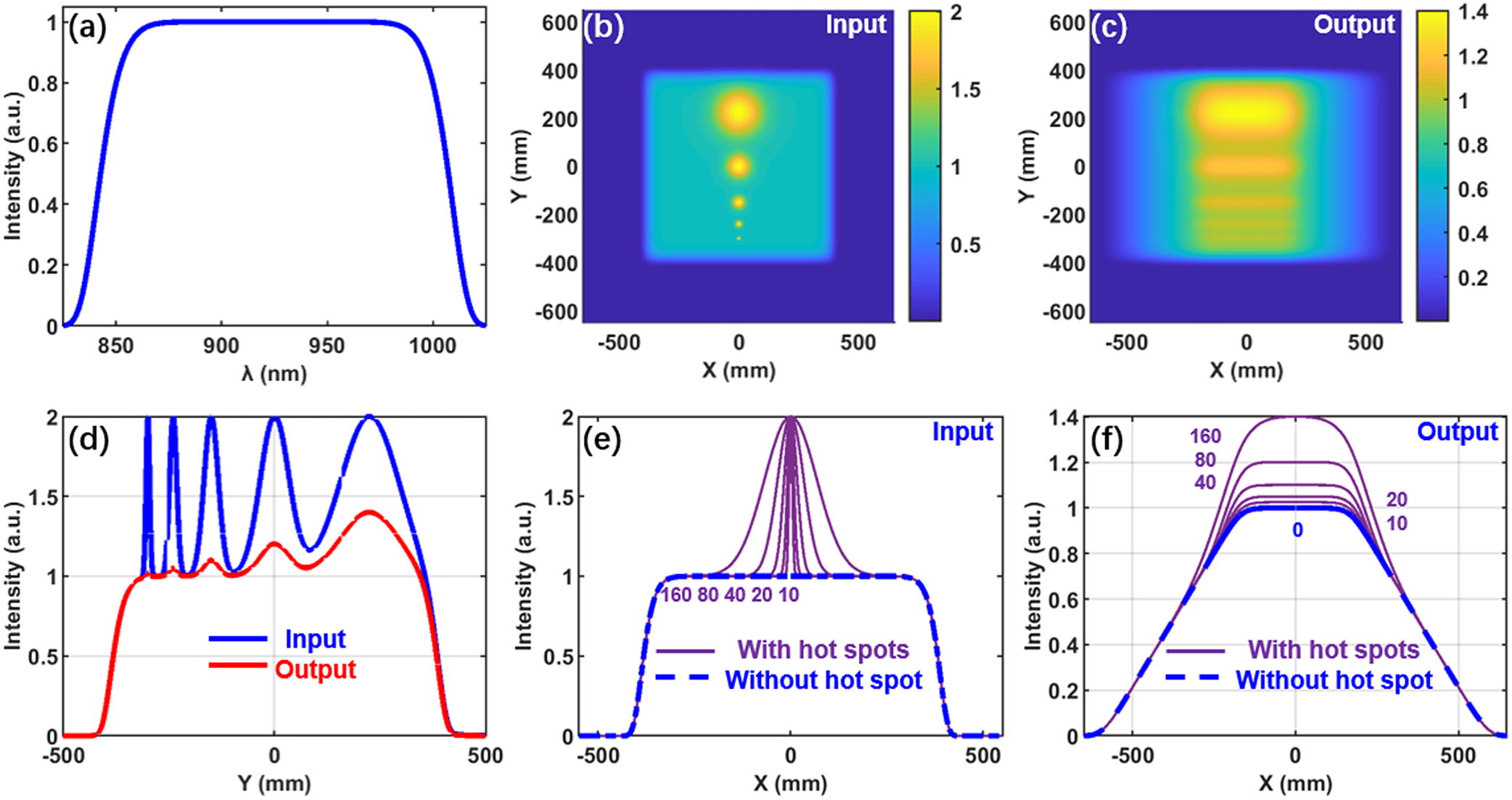
In the input beam, five Gaussian shape hot spots with different full width at half maximum (FWHM) diameters (10, 20, 40, 80 and 160 mm, respectively) but equal intensity are added to the beam so that the spatial intensity modulation is 2.0, as shown in Figure 2(b). The blue curve in Figure 2(d) shows the intensity profile in Figure 2(b) at X = 0, and the purple curves in Figure 2(e) show the intensity profiles with hot spots along the horizontal direction across the five peak points in Figure 2(b).
In the output beam, the introduced 520 mm spatial chirp smooths the beam, as shown in Figure 2(c). The red curve in Figure 2(d) shows the smoothed intensity profile in Figure 2(c) when X = 0, and the purple curves in Figure 2(f) show that the smoothed intensity profiles with hot spots along the horizontal direction pass the five peak points in Figure 2(c).
The simulation shows that spatial intensity modulations of input beams with hot spot FWHM diameters of less than 40 mm can be smoothed from 2.0 to less than 1.1 effectively, which illustrates that the SSGP compressor can smooth the output beam and protect the last compressor grating.
2.3 Near-field properties
The spectral-clipping effect occurred on both sides of G2 because of the limited grating size. Considering the gratings used are with the same size, 1600 mm × 1000 mm, and the input beam size is 860 mm × 860 mm, Figures 3(a) and 3(b) show the output beam profiles without and with spectral clipping, respectively, and the spectral clipping introduces an energy loss of about 7.8%, as shown in Figure 3(c).
Output beam profiles without (a) and with (b) spectral clipping introduced by the limited grating size of G2. (c) Beam profiles at Y = 0 in (a) (red solid curve) and (b) (blue dashed curve) for the SSGP compressor, and the beam profiles output from G2 at Y = 0 without (green solid curve) and with (purple dashed curve) spectral clipping for a symmetric four-grating compressor. Spectral–spatial coupling profiles without (d) and with (e) spectral clipping. (f) The input spectrum (red solid curve) and the integrated output spectrum with spectral clipping (blue dashed curve). (g) Spectral profiles at positions 434 mm (solid curve), 217 mm (dashed curve) and 0 mm (dotted curve) away from the center on the left-hand side. (h) FTL temporal profiles at the same three positions, 434 mm (solid curve), 217 mm (dashed curve) and 0 mm (dotted curve). (i) FTL temporal profiles of the output spectrum without (red solid curve) and with (blue dashed curve) spectral clipping.

Spectral clipping for the symmetric four-grating compressor also exists, where the induced spatial chirp width on the second grating (G2) is 260 mm or half that of the SSGP compressor (520 mm). The introduced pulse-energy loss is about 1.8%, as also shown in Figure 3(c).
Although the spectral-clipping-induced energy loss is increased for the SSGP compressor, as there are only two gratings used in the SSGP compressor, the diffraction loss is greatly reduced compared to that of the four-grating main compressor. Assuming a diffraction efficiency of 90% for every grating, the total compression efficiencies for the SSGP compressor and the four-grating compressors are 73.2% and 63.8%, respectively. In other words, the compression efficiency is improved by 1.15 times (73.2/63.8) using an SSGP compressor compared to that of a four-grating compressor.
The spectral–spatial coupling profiles of the output beam introduced by the 520 mm spatial chirp are shown in Figures 3(d) and 3(e) for beams without and with spectral clipping, respectively. Parts of the long and short wavelength spectra are clipped and cause the integrated output spectrum to lose energy on both sides of the spectrum, as shown in Figure 3(f) (blue dashed curve). The pulse width becomes 14.6 fs compared with the Fourier transform-limited (FTL) pulse width of 14.3 fs [Figure 3(i)].
For the spectral–spatial coupling profiles shown in Figure 3(e) with spectral clipping, Figure 3(g) shows the spectral profiles at positions 434, 217 and 0 mm away from the center on the left-hand side, where position 434 mm is at the left-hand edge of the output beam. About 240 mm width in the center along the horizontal direction still has the full spectra as the input beam. Figure 3(h) shows the FTL temporal profiles at the same three positions, 0, 217 and 434 mm, and the FWHM pulse durations are approximately 14.3, 16.5 and 37.3 fs, respectively. The spectral clipping that causes modulation occurs at less than half the peak intensity away from the top hat region[ Reference Du, Shen, Liang, Wang, Liu and Li 13 , Reference Ohtsuka and Yin 20 ], as shown in Figure 3(c).
It is known that the spectral clipping in the stretcher induces temporal contrast degradation due to the relatively small beam size compared with stretcher optics. For ultrahigh peak-power lasers with a beam size of hundreds of millimeters, the spectral clipping only induces spectral clipping on both sides of the laser beam, and the central top hat region still has a full spectral bandwidth without spectral clipping. The influence of spectral clipping in the compressor on the final temporal contrast can be neglected[ Reference Li, Dai, Wang and Xu 21 ], while a later section discusses the far-field properties.
3 Multistep pulse compressor with the single-pass single-grating-pair main compressor
3.1 Schematic of the MPC
We proposed a feasible design based on the MS-MPC using the SSGP main compressor to achieve a 10s–100s PW high peak-power laser with a single laser beam. The schematic of the entire SSGP-main-compressor-based MPC is shown in Figure 4. The beam-smoothing process includes three stages.
Optical diagrammatic sketch of the SSGP-main-compressor-based MPC. PS_I, PS_II_X: prism pair system. DM_1, DM_2, DM_3: reflective deformable mirrors with different sizes. BE: beam expander and relay imaging systems. G1, G2: diffraction gratings. M1–M5: reflective mirrors. PM: parabolic reflective mirror. FP: focal point.

In smoothing stage_0, a prism pair PS_I introduces a spatial chirp width of about 2–3 mm in the horizontal direction to smooth the incident laser beam before the main amplifier. All the potential hot spots on the main amplification crystal because of spatial intensity modulation in the near field and wavefront aberration in the far field are insulated. As for a super-Gaussian laser beam of several hundred millimeters, the influence of the induced several millimeters of spatial chirp width on the amplification process can be neglected.
In smoothing stage_1, which is also the pre-compressor stage, a prism pair PS_II_X introduces a suitable spatial chirp width of less than 10 mm in the horizontal direction to smooth the laser beam after the main amplifier. Together with the subsequent spatial-filter-based beam expander (BE), which filters out most of the wavefront aberration at the high spatial frequency, the rest of the wavefront aberration at the high/middle spatial frequency is also smoothed. Smoothing stage_1 mainly protects the large optics, especially the first grating G1 and DM_2.
In smoothing stage_2, which is also the main compressor, the SSGP compressor composed of G1 and G2 induces a spatial chirp width of several hundred millimeters to the output beam, and protects the last grating, G2, which is the most easily damaged grating because of the shortest pulse duration on it. This extremely smoothed laser in terms of both spatial intensity and wavefront aberration also protects the final deformable mirror, DM_3.
Finally, a parabolic reflective mirror (PM) is used as the post-compressor to compensate for the previously induced spatial chirp at the focal point based on the spatiotemporal focusing effect[ Reference Liu, Shen, Du and Li 11 , Reference Zhu, van Howe, Durst, Zipfel and Xu 22 , Reference He, Zeng, Chu, Ni, Sugioka, Cheng and Durfee 23 ].
3.2 Wavefront compensation
According to previous studies[ Reference Li and Miyanaga 14 – Reference Pariente, Gallet, Borot, Gobert and Quéré 16 ], in a symmetric four-grating compressor, the wavefront aberrations induced by the second and third gratings (G2 and G3) mainly affect the spatiotemporal properties at the focal point, while the wavefront aberration cannot be compensated using a deformable mirror before or after the compressor. A transmitted compensation plate was proposed, located between G2 and G3[ Reference Liu, Shen, Du and Li 11 , Reference Liu, Shen, Si, Wang, Zhao, Liang, Leng and Li 24 ], to partly compensate for the static wavefront aberration induced by G2 and G3. However, the compensation plate cannot compensate for the dynamic wavefront aberrations, such as the heat-, vacuum- and installation-induced aberrations in the compressor[ Reference Leroux, Eichner and Maier 15 ]. Another compensation method is using a deformable mirror after the stretcher with a small beam size[ Reference Li and Kawanaka 25 ], which is not a direct method.
In the proposed MS-MPC with the SSGP main compressor, three deformable mirrors are used to compensate for the wavefront aberration and the spatiotemporal distortion at different stages, as shown in Figure 4.
The first deformable mirror with small size, DM_1, is used to ensure that the wavefront before PS_II_X is flat and well compensated. Here, the reflective light from the first prism is used as the wavefront monitoring light, which is firstly beam reduced and then fed back to DM_1, as shown in Figure 5(a).
Optical diagrammatic sketch for the wavefront aberration measuring and controlling of (a) DM_1, (b) DM_2 and (c) DM_3. DM_1, DM_2, DM_3: the reflective deformable mirrors corresponding to Figure 4. PM: parabolic reflective mirror.
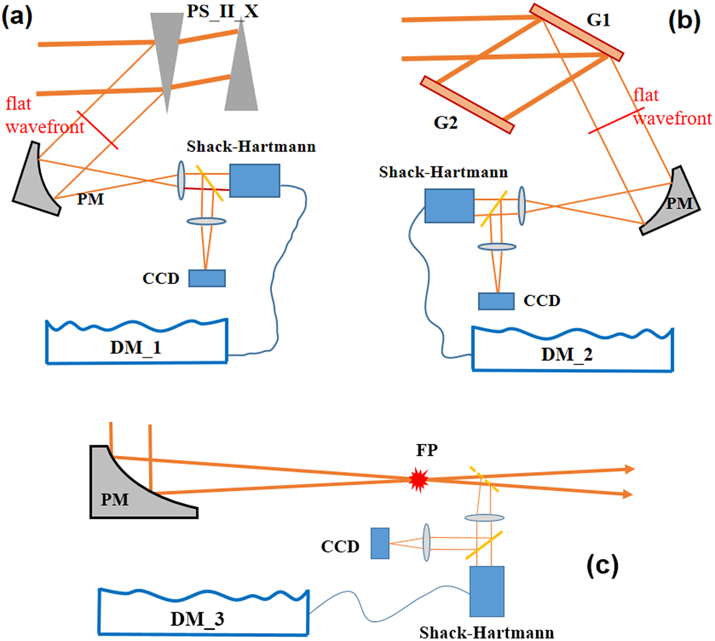
After PS_II_X, the second deformable mirror, DM_2, is used to compensate for the induced wavefront aberration by the optics from PS_II_X to G1 (inclusive). Here, the reflective light or zero-order diffraction light from G1 is used for wavefront monitoring, which first passes a beam reducer and then feeds back to DM_2, as shown in Figure 5(b).
After G1, all the wavefront aberrations induced by the optics after G2 can be compensated effectively by using the third reflective deformable mirror, DM_3, located after the compressor. Since different wavelengths from G1 with different incident angles are collimated by G2, the wavefront error of G2 can only be well compensated at a fixed wavelength, typically at the central wavelength, by DM_3. As a result, the wavefront errors of other wavelengths away from the central wavelength cannot be completely compensated due to different incident angles, which are turned into the spectral phase distortion and affect the temporal properties of output pulses at every point on the beam. A wavefront corrective measurement, but not monitoring, system for DM_3 is located near the final focal point to ensure the best focal intensity, as shown in Figure 5(c).
The imperfect optical elements in the measurement optical path, such as the lenses, PMs, beam splitters and even the vacuum chamber windows (not shown here) in Figure 4, will bring extra wavefront aberration. A calibration should be used to remove the influence by using a point light source located at the position of the charge-coupled device (CCD), and a removable standard mirror with a perfect flat (used in Figures 5(a) and 5(b)) wavefront is located before the first optical element in the measurement optical path. This wavefront aberration can then be directly measured by a Shack–Hartmann sensor. Furthermore, by inducing an alignment light at the CCD position, this setup can also be used to precisely align the off-axis-parabolic BE system before the main compressor, which will improve the daily operation of the PW laser system[ Reference Ohland, Zobus, Eisenbarth, Zielbauer, Reemts and Bagnoud 26 ].
A standard interferometer, such as ZYGO, can also be used to precisely measure wavefront aberration. With a known wavefront aberration of the entire measurement optical path, as shown in Figure 5(b), the reflective output beam from G1 is expected to have a well-compensated flat wavefront. Note that the diffraction wavefront of the gratings included two parts: the reflective wavefront aberration and the static diffraction wavefront distortion induced by the error or imperfect grating lines, where the static diffraction wavefront distortion can be well measured offline. In this way, the diffractive laser beam output from G1 is also expected to have a compensated flat wavefront. Moreover, the monitoring lights for both DM_1 and DM_2 are not on the main beam optical line, indicating that both deformable mirrors can compensate the wavefront distortion in real time. This is important for improving the laser operational and experimental efficiency in the future.
Based on the three compensation systems described above, all the wavefront aberration with low spatial frequency can be compensated in the SSGP-based MPC. The laser beam used for wavefront monitoring in Figures 5(a) and 5(b) can simultaneously monitor the laser spectrum, pointing stability and energy stability, thus improving the operating efficiency of the laser facility.
3.3 Far-field properties
Assuming complete spectral chirp compensation, the 520 mm spatial chirp introduced by the SSGP compressor will affect the far-field properties of the output beam. It is focused by a parabolic mirror, as shown in Figure 4. Focusing of a spatially chirped beam, so-called spatiotemporal focusing[ Reference Zhu, van Howe, Durst, Zipfel and Xu 22 , Reference He, Zeng, Chu, Ni, Sugioka, Cheng and Durfee 23 ], has been successfully used in two-photon microscopy and ultrafast micro-machining applications to increase the axial resolution of the optical section function and has also been explored in our previous works to focus beams with spatial chirp[ Reference Liu, Shen, Du and Li 11 , Reference Shen, Du, Liang, Wang, Liu and Li 12 ].
The focal length of the parabolic mirror is set to be 3 m, and analytic calculation based on Fresnel diffraction is used to explore the properties around the focal point[ Reference Shen, Du, Liang, Wang, Liu and Li 12 , Reference Zhu, van Howe, Durst, Zipfel and Xu 22 ]. For simplicity in the analytic calculation, both the beam and spectrum are assumed to be Gaussian profiles with beam full width of about 860 mm and FWHM pulse duration of about 14.3 fs. No spectral clipping is considered here.
Figures 6 (a) and 6(b) show the X–Z plane intensity distributions around the focal point for output beams without and with 520 mm spatial chirp, respectively. Figure 6(c) compares the intensity profiles at $x=0$
in Figures 6(a) and 6(b). It shows that the intensity of the focused beam with 520 mm spatial chirp undergoes a faster evolution around the focal point than that without spatial chirp, while at the focal point (z = 0), the intensities are the same for both conditions, and at the position
$x=0$
in Figures 6(a) and 6(b). It shows that the intensity of the focused beam with 520 mm spatial chirp undergoes a faster evolution around the focal point than that without spatial chirp, while at the focal point (z = 0), the intensities are the same for both conditions, and at the position $z=\pm 5\;\unicode{x3bc} \mathrm{m}$
, the intensity difference is approximately 0.6%.
$z=\pm 5\;\unicode{x3bc} \mathrm{m}$
, the intensity difference is approximately 0.6%.
Intensity distributions in X–Z planes for beams without (a) and with 520 mm spatial chirp (b). (c) Intensity profiles at $x=0$
in (a) and (b), red solid curve for (a), blue solid curve for (b) and purple dashed curve for the difference between them.
$x=0$
in (a) and (b), red solid curve for (a), blue solid curve for (b) and purple dashed curve for the difference between them.

For the properties in the focal plane, the influence of both the spatial chirp and spectral clipping is considered. Fourier pulse propagation is used to obtain the properties[ Reference Shen, Du, Liang, Wang, Liu and Li 12 ].
With the input beam size of 860 mm × 860 mm, Figures 7(1b)–7(1d) show the far-field properties of a beam output from an ideal typical four-grating compressor without spatial chirp and spectral clipping, while the near-field beam intensity profile is shown in Figure 7(1a) with a beam size of 860 mm × 860 mm. Figures 7(2b)–7(2d) show the far-field properties of a beam output from the SSGP compressor with 520 mm spatial chirp and spectral clipping, while the near-field beam intensity profile is shown in Figure 7(2a) with a beam size of 860 mm × 860 mm that was limited by the 1600 mm × 1000 mm grating size. Figure 7(2c) shows that the introduced spatial chirp along the horizontal direction induces a slight pulse front tilt, which is the special property of spatiotemporal focusing. Usually, it has a detrimental impact for many laser–plasma interactions, but also it has an interesting impact on the energy and direction of accelerated electrons and the surface micromachining[ Reference Wilhelm and Durfee 27 – Reference Feng, Li, Wang, Li, Zhu, Tan, Geng, Liu and Chen 29 ]. Figures 7(3a)–7(3d) show the intensity curves in the center along the horizontal axis of the figures above each one.
(1a) Near-field beam intensity without spatial chirp and spectral clipping. (1b)–(1d) Properties in the focal plane of the beam shown in (1a). (2a) Near-field beam intensity with 520 mm spatial chirp and spectral clipping. (2b)–(2d) Properties in the focal plane of the beam shown in (2a). (3a)–(3d) Intensity curves in the center along the horizontal axis of the figures above each one. The profiles in the X versus T, Y versus T and X versus Y planes are the projections in these planes of the spatial-temporal information in the focal plane.

The two focal point intensity profiles shown in Figures 7(1d) and 7(2d) are also almost the same except for the 0.15 intensity difference; this is because the sizes of the two beams output from the two compressors are almost the same; the intensity profiles shown in Figure 7(3d) have the same normalized shape. In the X versus T plane, the pulse duration increases slightly. In the Y versus T plane, pulse front tilt appears.
The integrated temporal profiles at the focal point are shown in Figure 8, wherein pulse duration increases about 11% from 14.3 to 15.9 fs, as shown in Figure 8(a), while the influence of the spatial chirp and spectral clipping on the temporal contrast can be neglected, as shown in Figures 8(b) and 8(c); the temporal contrast is under 10–12 400 fs away from the center pulse.
(a) Integrated temporal profiles in the focal plane in linear (a) and log (b), (c) scales, where the blue curve represents the ideal condition and the red curve represents the beam output from the SSGP compressor.

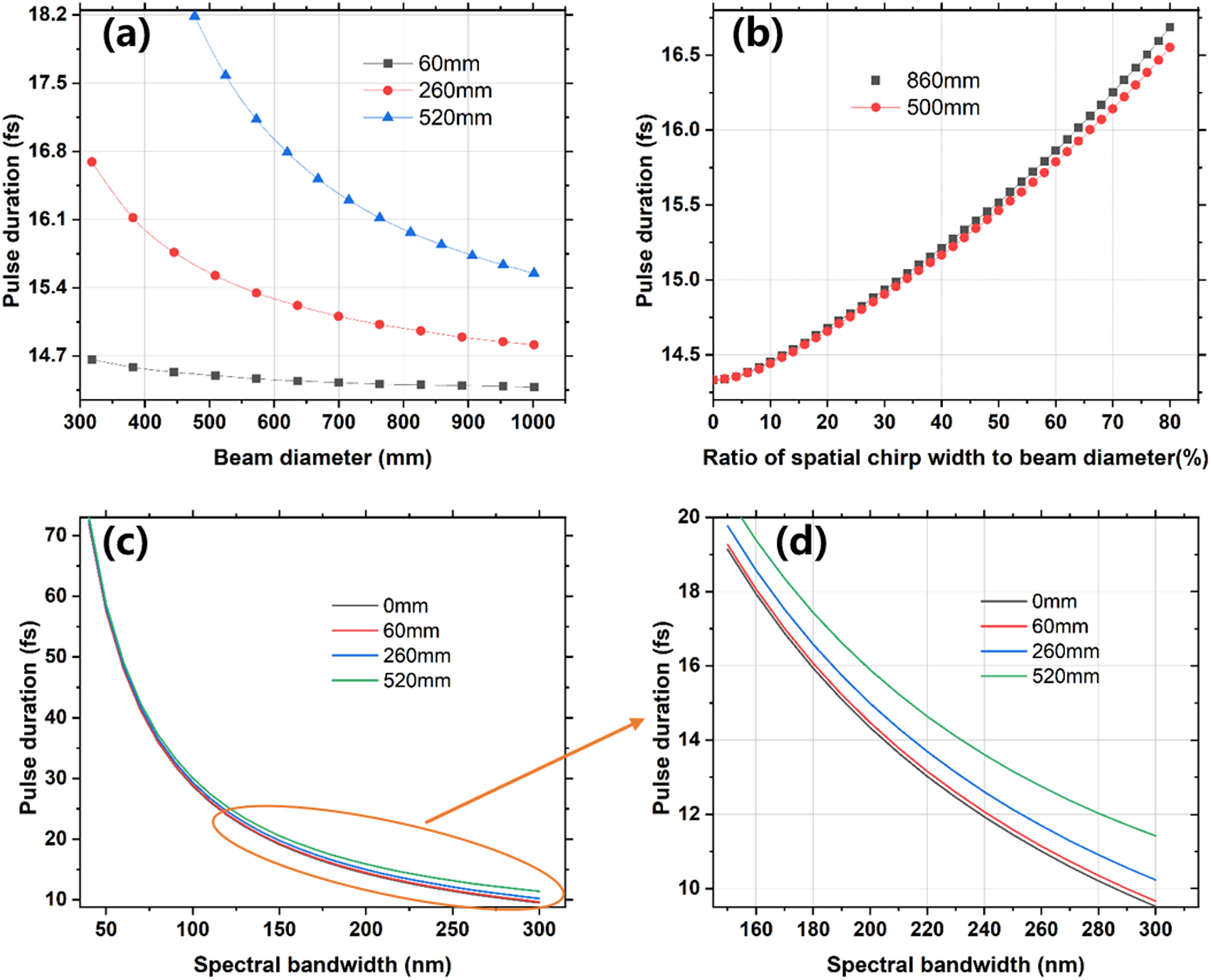
Furthermore, the influences of the ratio of the spatial chirp region, the beam diameter and the spectral bandwidth to the pulse duration on the focal point are also calculated and analyzed, as shown in Figure 9. According to Figure 9(a), the pulse duration at the focal point is broadened as the induced spatial chirp width increases, while it decreases as the beam diameter increases. Figure 9(b) shows that the pulse duration at the focal point is mainly related to the ratio of the spatial chirp width in a laser beam. Figures 9(c) and 9(d) show that the spatial chirp-induced pulse duration broadening at the focal point is also slightly increased as the spectral bandwidth increased. This indicates that the SSGP compressor is more suitable for ultrahigh peak-power lasers with narrow spectral bandwidths, which had a small influence on the final focal intensity and has been proved in several PW facilities[ Reference Danson, Brummitt, Clarke, Collier, Fell, Frackiewicz, Hancock, Hawkes, Hernandez-Gomez, Holligan, Hutchinson, Kidd, Lester, Musgrave, Neely, Neville, Norreys, Pepler, Reason, Shaikh, Winstone, Wyatt and Wyborn 18 , Reference Neumayer, Bock, Borneis, Brambrink, Brand, Caird, Campbell, Gaul, Goette, Haefner, Hahn, Heuck, Hoffmann, Javorkova, Kluge, Kuehl, Kunzer, Merz, Onkels, Perry, Reemts, Roth, Samek, Schaumann, Schrader, Seelig, Tauschwitz, Thiel, Ursescu, Wiewior, Wittrock and Zielbauer 19 ].
Curves of the pulse duration at the focal point related to (a) the beam diameter, (b) the ratio of the spatial chirp region and (c), (d) the spectral bandwidth, at different induced spatial chirp widths (0, 60, 260, 520 mm) and beam sizes (500 and 860 mm), respectively.
4 Proof-of-principle experiment and 50–100 PW design
A two-grating compressor was set up after a kHz Ti:sapphire amplifier (Coherent, Legend) to experimentally prove the feasibility of the SSGP main compressor with relatively broad spectral bandwidth and large spatial chirp width proportion. The full spectral bandwidth of the laser pulse ranged from 760 to 830 nm with a Gaussian spectral profile, and the FWHM spectrum was about 20 nm. The two compression gratings were home-made 1480 grooves/mm gold-coated gratings with a size of 150 mm × 200 mm, with an incident angle of 56o. The distance between the two gratings is approximately 600 mm to fully compensate for the spectral chirp, inducing about 42 mm spatial chirp width to the output laser beam, as shown in Figure 10(a). For a 50-mm-diameter input laser beam, the central part of the output laser beam with full spectral bandwidth was 8 mm, indicating that the ratio of the spatial chirp width to the laser beam was almost 90%.
(a) Experimental setup of an SSGP main compressor; (b) spatial intensity modulations on the laser beam before G1; (c) output laser beam after the SSGP compressor; (d) temporal profiles at the focal point for single-pass and double-pass single-grating pairs; and (e) the spectral bandwidth of the input beam with a Gaussian profile.

The strong spatial intensity modulation in the beam before G1, as shown in Figure 10(b), can be smoothed effectively, as shown in Figure 10(c). After the SSGP compressor, the temporal profile at the focal point was measured by using the SHG-FROG method with a retrieval error of less than 0.005, as shown in Figure 10(d). The retrieved FWHM pulse duration is about 49 fs, which is close to the Fourier transform-limited pulse duration of 47 fs. The temporal profiles at the focal point in the experiment clearly demonstrate the feasibility of the SSGP main compressor. Narrow bandwidth lasers with an SSGP compressor or a similar SSGP compressor have been applied in PW lasers, such as the Vulcan, the PHELIX and the PETAL PW laser facilities[ Reference Danson, Brummitt, Clarke, Collier, Fell, Frackiewicz, Hancock, Hawkes, Hernandez-Gomez, Holligan, Hutchinson, Kidd, Lester, Musgrave, Neely, Neville, Norreys, Pepler, Reason, Shaikh, Winstone, Wyatt and Wyborn 18 , Reference Neumayer, Bock, Borneis, Brambrink, Brand, Caird, Campbell, Gaul, Goette, Haefner, Hahn, Heuck, Hoffmann, Javorkova, Kluge, Kuehl, Kunzer, Merz, Onkels, Perry, Reemts, Roth, Samek, Schaumann, Schrader, Seelig, Tauschwitz, Thiel, Ursescu, Wiewior, Wittrock and Zielbauer 19 , Reference Blanchot, Behar, Chapuis, Chappuis, Chardavoine, Charrier, Coic, Damiens-Dupont, Duthu, Garcia, Goossens, Granet, Grosset-Grange, Guerin, Hebrard, Hilsz, Lamaignere, Lacombe, Lavastre, Longhi, Luce, Macias, Mangeant, Mazataud, Minou, Morgaint, Noailles, Neauport, Patelli, Perrot-Minnot, Present, Remy, Rouyer, Santacreu, Sozet, Valla and Laniesse 30 ], all of which partly enhance the feasibility of the SSGP compressor with a broad spectral bandwidth.
The optical diagrammatic sketch, shown in Figure 4, can be used to design a 50–100 PW laser output by using the SSGP-based MPC. For gold-coated gratings, the damage threshold is about 0.2 J/cm2 for femtosecond pulses on the last grating, which limits the maximum output pulse energy or peak power[
Reference Liu, Shen, Du and Li
11
,
Reference Liu, Shen, Si, Wang, Zhao, Liang, Leng and Li
24
]. As the spatial intensity modulation ratio of the laser beam can be smoothed to less than 1.1 owing to the induced hundreds of millimeters spatial chirp width to the output laser beam, a $\sqrt{2}$
times spatial intensity modulation ratio is reserved instead of the typical 2.0 for the input laser beam. This setting can make sure that the last grating is safe, which corresponds to the maximum energy density on the last grating of 0.141 J/cm2. Here, the energy density distribution on G2 is used as the calculation reference. For a commercially available grating with an effective area of approximately 1400 mm × 660 mm, when considering the approximately 1–80% = 20% non-full-filled area on both sides of the blue dashed curve, similar to the Figure 3(c), the maximum compressed output pulse energy should be about 140 × 65 × 0.141 × 80% = 1026 J. After spatiotemporal focusing, about 16.6 fs at the focal point can be obtained according to Figure 9(a) with about 650 mm beam size, and the corresponding focused peak power will be about 1026 J/16.6 fs = 61.8 PW. For a gold-coated grating with an effective area of about 1600 mm × 1000 mm, the maximum compressed output pulse energy should be about 160 × 95 × 0.141 × 80% = 1715 J, where 80% is also the ratio of the blue dashed curve covered area, as shown in Figure 3(c), to a rectangular area of about 900 mm × 1 mm. According to Figure 9(a), about 15.7 fs at the focal point can be achieved after spatiotemporal focusing, which resulted in about 1715 J/15.7 fs = 109.2 PW.
$\sqrt{2}$
times spatial intensity modulation ratio is reserved instead of the typical 2.0 for the input laser beam. This setting can make sure that the last grating is safe, which corresponds to the maximum energy density on the last grating of 0.141 J/cm2. Here, the energy density distribution on G2 is used as the calculation reference. For a commercially available grating with an effective area of approximately 1400 mm × 660 mm, when considering the approximately 1–80% = 20% non-full-filled area on both sides of the blue dashed curve, similar to the Figure 3(c), the maximum compressed output pulse energy should be about 140 × 65 × 0.141 × 80% = 1026 J. After spatiotemporal focusing, about 16.6 fs at the focal point can be obtained according to Figure 9(a) with about 650 mm beam size, and the corresponding focused peak power will be about 1026 J/16.6 fs = 61.8 PW. For a gold-coated grating with an effective area of about 1600 mm × 1000 mm, the maximum compressed output pulse energy should be about 160 × 95 × 0.141 × 80% = 1715 J, where 80% is also the ratio of the blue dashed curve covered area, as shown in Figure 3(c), to a rectangular area of about 900 mm × 1 mm. According to Figure 9(a), about 15.7 fs at the focal point can be achieved after spatiotemporal focusing, which resulted in about 1715 J/15.7 fs = 109.2 PW.
5 Conclusion
In conclusion, an improved MPC based on an SSGP main compressor is studied systematically. Compared with the previous MPC based on the AFGC, the SSGP main compressor-based MPC shows many advantages, such as saving compared with two expensive gratings, simplifying the setup, simplifying the vacuum chamber of the main compressor, improving the beam-smoothing effect of the output laser beam and increasing the total compression efficiency. Although the output beam has pulse front tilt, it can be controlled using non-collimated beams in an SSGP compressor[ Reference Blanchot, Behar, Chapuis, Chappuis, Chardavoine, Charrier, Coic, Damiens-Dupont, Duthu, Garcia, Goossens, Granet, Grosset-Grange, Guerin, Hebrard, Hilsz, Lamaignere, Lacombe, Lavastre, Longhi, Luce, Macias, Mangeant, Mazataud, Minou, Morgaint, Noailles, Neauport, Patelli, Perrot-Minnot, Present, Remy, Rouyer, Santacreu, Sozet, Valla and Laniesse 30 , Reference Figueira, Braga, Ahmed, Boyle, Galimberti, Galletti and Oliveira 31 ], where an off-axis-parabolic telescope can be used for the beam transport and expander before the SSGP compressor[ Reference Ohland, Zobus, Eisenbarth, Zielbauer, Reemts and Bagnoud 26 ]. Furthermore, the wavefront aberration at the central wavelength induced by all the gratings can be compensated effectively by using three deformable mirrors, which can result in a higher focal intensity. This property can also reduce the wavefront aberration requirement of large gratings, which are difficult or expensive to control effectively during the manufacturing and installation processes. As the two-grating distance is long enough in the SSGP main compressor, a shorter 3.0 or 3.5 ns chirped pulse instead of a 4 ns chirped pulse, or typical 1480 groves/mm gratings, are feasible in this design, thus extending the choice range of many parameters to optimize the compressor further. All the above advantages make it a promising method for PW laser compressors with relatively large beam sizes, which will induce beam block if a four-grating compressor is used. In the near future, by using this SSGP-based MPC with a single laser beam, approximately 60 or 100 PW lasers can be obtained by using only two 1400 mm × 660 mm or 1600 mm × 1000 mm gold-coated gratings, respectively.
Acknowledgements
The authors would like to thank Dr. Yunxia Jin for supplying gratings for the experiment, and Dr. Chenqiang Zhao and Dr. Lianghong Yu for helpful discussion. This work was supported by the National Natural Science Foundation of China (NSFC) (Nos. 61527821, 61905257, and U1930115) and the Shanghai Municipal Science and Technology Major Project (No. 2017SHZDZX02).


 Open access