


Introduction
Bycatch is an important consideration in an ecosystem-based approach to management of fisheries (Gilman et al., Reference Gilman, Passfield and Nakamura2014). Bycatch refers to the accidental capture of non-target marine organisms or undersized target species, which can result in discarding of the unwanted catch that are often dead (Kelleher, Reference Kelleher2005). Discarding can cause difficulties in estimating fishing mortality, productivity and stock abundance (Catchpole et al., Reference Catchpole, Frid and Gray2005). Discarding occurs for various reasons, including (i) regulatory restrictions: quota limitations, minimum landing sizes (MLS) or protected status; (ii) quality of catch: damage or contamination; (iii) value of catch: species vary in market value, which can result in high-grading i.e. strategically discarding low-value species that can be legally landed (Kelleher, Reference Kelleher2005; Gilman et al., Reference Gilman, Passfield and Nakamura2014).
The European Union (EU) have implemented the landings obligation (LO), whereby discarding quota species is banned, instead it is required that all EU quota species are landed and recorded (EC, 2013). This legislation requires that fishers either (i) hold sufficient quota to land the bycatch of quota species; (ii) prove that discard survivability rates of species are high enough to permit continued discarding (survivability exemption); (iii) implement bycatch reduction strategies to eliminate or significantly reduce rates of bycatch; or (iv) if scientific evidence proves increased selectivity is difficult to achieve, a de minimis exemption may permit fishers to discard quota-regulated species that are caught in minor quantities (often 5% of the weight of target catch). These catches will not be counted against the quota but must be documented (EC, 2018). If species are landed surplus to available quota, this could result in the early closure of that fishery (known as ‘choking’). For these reasons, the reduction of bycatch is of paramount concern for many fisheries in Europe.
Technological modifications to fishing gear can be utilized to improve selectivity and avoid the capture of unwanted catch. Bycatch reduction devices (BRDs) can be designed to (i) select individuals mechanically, eliminating or reducing catches of non-target or undersize target organisms by size and shape; and (ii) exploit behavioural differences in target and bycatch species, relying on species coming into contact with the panel to encourage escapement (Broadhurst, Reference Broadhurst2000; Santos et al., Reference Santos, Herrmann, Otero, Fernandez and Pérez2016). Square mesh panels (SMP) are a form of BRD that incorporates a panel of large square mesh into a traditional diamond mesh net, selecting species mechanically, thereby allowing below MLS individuals to escape or eliminating non-target species by exploiting their behaviour. For example, in otter trawls, gadoid bycatch have the capability to escape through a SMP fitted in the upper panel of a net, as they have a higher motor ability than the target species such as scallops or prawns, which remain in the lower sections of the net (Broadhurst, Reference Broadhurst2000; Courtney et al., Reference Courtney, Campbell, Roy, Tonks, Chilcott and Kyne2008). The effectiveness of a SMP to select species by size is dependent on the mesh size used, and on seasonal variations affecting fish condition (Brčić et al., Reference Brčić, Herrmann and Sala2016; Fryer et al., Reference Fryer, O'Neill and Edridge2016). Additionally, the effectiveness of SMPs can depend on the panel position, with escapement highest when the distance between the SMP and codline is smallest (Brčić et al., Reference Brčić, Herrmann and Sala2016). Selectivity can vary between bycatch species, for example, cod (Gadus morhua) and haddock (Melanogrammus aeglefinus) exhibit different swimming patterns in response to trawls. Cod tend to enter the trawl at the level of the fishing line and remain low in the net, exhibiting low swimming activity, while haddock swim in a more erratic manner, which increases their chances of escapement through BRDs (Ferro et al., Reference Ferro, Jones, Kynoch, Fryer and Buckett2007; Grimaldo et al., Reference Grimaldo, Larsen and Holst2007; Krag et al., Reference Krag, Holst and Madsen2009). Subtle changes in environmental parameters can also influence gear selectivity, e.g. water current and temperature can affect the maximum swimming performance of fish (Wardle, Reference Wardle, MacDonald and Priede1983; Michalsen et al., Reference Michalsen, Godo and Ferno1996; Broadhurst, Reference Broadhurst2000). Similarly, the catchability of species varies depending on the habitat they live within, for instance depth level can influence their visual capacity and resultant ability to avoid gears (Nguyen & Winger, Reference Nguyen and Winger2019).
The use of artificial light to enhance gear selectivity is of increasing interest. However, behavioural responses to light are species specific (Ben-Yami, Reference Ben-Yami1976; Nguyen & Winger, Reference Nguyen and Winger2019), with light either stimulating a reduction or increase in catches for some species, while having no effect on others (Lomeli & Wakefield, Reference Lomeli and Wakefield2012; Larsen et al., Reference Larsen, Herrmann, Sistiaga, Brinkhof, Tatone and Langård2017, Reference Larsen, Herrmann, Sistiaga, Brinkhof and Grimaldo2018; Melli et al., Reference Melli, Krag, Herrmann and Karlsen2018; Lomeli et al., Reference Lomeli, Wakefield and Herrmann2018a). Grimaldo et al. (Reference Grimaldo, Sisitiaga, Herrmann, Larsen, Brinkhof and Tatone2017) placed LEDs within a SMP and found that lights stimulated escape behaviour in haddock but not in cod. Also, when implementing light as a tool to manipulate fish behaviour, technical parameters such as colour, intensity, wavelength and strobing need to be considered (Ben-Yami, Reference Ben-Yami1976; Marchesan et al., Reference Marchesan, Spoto, Verginella and Ferrero2005; O'Neill et al., Reference O'Neill, Feekings, Fryer and Fauconnet2019), which can also vary depending on the fishing environment. For instance, fish vision is reduced in deep water due to the lower ambient light levels (Kim & Wardle, Reference Kim and Wardle1998). Fish behaviour also changes depending on the configuration of the lights within the trawl – lights fitted to the fishing line can either repel fish or increase their awareness of the oncoming trawl (Hannah et al., Reference Hannah, Lomeli and Jones2015; Lomeli et al., Reference Lomeli, Wakefield and Herrmann2018a, Reference Lomeli, Groth, Blume, Herrmann and Wakefield2018b). In contrast, lights fitted to the escape panel can guide fish towards escape routes (Ben-Yami, Reference Ben-Yami1976; Lomeli & Wakefield, Reference Lomeli and Wakefield2014; Elliott & Catchpole, Reference Elliott and Catchpole2015; Grimaldo et al., Reference Grimaldo, Sisitiaga, Herrmann, Larsen, Brinkhof and Tatone2017). Some fisheries currently use light as a tool to increase catches through attracting species towards fishing gear, notably squid jigs, herring purse seines and snow crab pots (Nguyen & Winger, Reference Nguyen and Winger2019). Collectively, these studies highlight the considerable variation in the behavioural response of fish to light, which is both species and environmentally specific.
The present study investigated the effect of using LED lights attached to a SMP designed to reduce the bycatch of gadoids in a Queen scallop (Aequipecten opercularis; QSC) trawl fishery in the Irish Sea, UK. Pre 2018 the QSC fishery was the second most valuable fishery in the Isle of Man (IoM) with ~3814 tonnes landed from ICES area VIIa (ICES rectangles 36E5, 37E5 and 38E5) worth ~£2.4 million annually (Manx Fish Producers Organisation (MPFO) personal communication, 2017). The bycatch levels (as a percentage of overall catch) for the fishery are relatively low at 7.4% (Boyle et al., 2016). Nevertheless, at present, the MFPO holds insufficient quota for this fishery to land bycatch species such as whiting (Merlangius merlangus), cod and haddock, hence the fishery may become ‘choked’ prematurely (MFPO personal communication, 2017). SMPs are effective at reducing gadoid bycatch and in some cases large mesh panels can reduce flatfish bycatch (Milliken & DeAlteris, Reference Milliken and DeAlteris2004). More recently artificial light has reduced both round and flatfish bycatch (Hannah et al., Reference Hannah, Lomeli and Jones2015; Nguyen & Winger, Reference Nguyen and Winger2019).
The objectives of the present study were to assess whether fish escapement could be enhanced relative to a standard commercial all diamond mesh net, through fishing with a modified net fitted with a SMP, or a net with a SMP and LED lights. The study was replicated in two different environments to understand how differences in environmental conditions affected the selectivity of bycatch species in the modified fishing gear.
Materials and methods
Experimental design
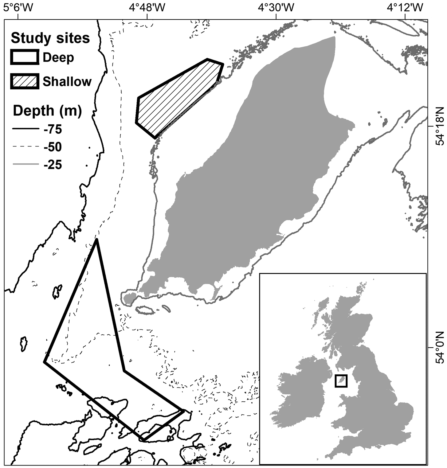
The study occurred from June–August 2017 during daylight hours. Fishing took place across two commercial fishing grounds in the Isle of Man territorial sea, known locally as Targets and Chickens (Figure 1). The sites vary in terms of bycatch composition, ground type and depth (Boyle et al., 2016), and are hereafter referred to as ‘shallow’ (Targets) and ‘deep’ (Chickens).
Areas fished within the commercial fishing grounds Targets (shallow) and Chickens (deep), during the gear trials (data sourced from GPS loggers used on board the vessels). Bathymetry data is also shown as Depth (m) (sourced from EMODnet.EU).
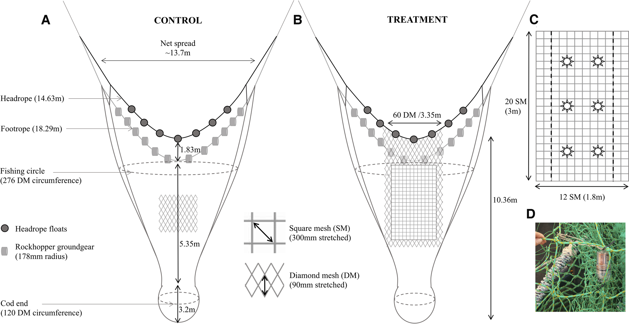
The trials were conducted utilizing two commercial fishing vessels of similar size and engine power, ‘Two Girls’ (TG; 13.88 m, 216.24 kW) and ‘Our Sarah Jane’ (OSJ; 13.98 m, 187 kW). The experiment adopted a paired tow design, whereby two nets were towed parallel to one another, one vessel towed the conventional all diamond mesh net (control) and the other vessel towed one of the treatment nets; either the (i) SMP alone or (ii) the SMP with LEDs attached (SMP+L) (Figure 2). Fishing procedures were consistent for both vessels and both nets were identical and new prior to the addition of the SMP to one of the nets. When testing the SMP+L treatment, six LED lights (SafetyNet Technologies Ltd) were attached to the SMP using cable ties and metal clips (Figure 2C, D). The LEDs were programmed to emit constant white light (luminous intensity 33 cd (candela); voltage 3.1 V). The lights were almost neutrally buoyant when in seawater.
The dimensions of (a) the control net, a conventional diamond mesh QSC otter trawl; (b) the treatment net, identical to the control, with the addition of a square mesh panel inserted aft of the fishing circle; and (c) a schematic of the placement of the six LED lights within the SMP. The SMP begins 1.8 m aft of the centre of the headrope and ends 0.5 m from the anterior section of the codend. Note that the IoM QSC net differs to conventional fish or prawn bottom trawls, as the diamond mesh near to the mouth of the net is held open due to the wider spaced meshes (i.e. 60 mesh into 3.35 m) SM, Square mesh; DM, Diamond mesh. (d) The SafetyNet LED light inserted within the SMP.
To minimize environmental and ‘vessel’ effects, the treatment net (SMP/SMP+L) and control net (all diamond mesh) were interchanged between fishing vessels after every second day. The vessels towed their fishing gear in parallel lines but switched their position from port to starboard after every tow. The treatments (SMP/SMP+L) were alternated sequentially every second tow throughout each day. Each vessel towed the nets on the same bearing (into the tide when feasible) at ~2.2 knots (speed over ground) and the warp released was standardized at three times the depth and tow duration was kept constant at 60 min.
Sampling design and data collection
Once emptied on deck, all fish were identified and counted. Total lengths (TL) of EU quota species were measured to the nearest 0.1 mm. The length/weight relationships of fish species were determined to estimate weights of each species caught per tow (Supplementary Table S1). Once the Queen scallops had been sorted through the mechanical riddle to eliminate undersized individuals, the number of standard-sized bags of marketable catch were recorded per tow and this value was subsequently multiplied by the weight of an average QSC bag (~35 kg; MFPO personal communication). The towing positions were recorded every minute using GPS loggers. Tow length was standardized to swept area, using a net spread ratio of 0.75 relative to the net headrope length (Figure 2) (Sterling, Reference Sterling2005).
Environmental variables that may have influenced catch per unit area (CPUA) were recorded per tow including: sea state (Beaufort scale), turbidity (Secchi disc; m), cloud cover (%). Ambient light levels in the net (lux) were recorded with a HOBO UA-002-64 64K Pendant Temp/Light Logger (Tempcon Ltd). Although the logger was incapable of detecting low natural ambient light levels, it was deployed on the treatment net (30 cm anterior of the square mesh panel) to record variations in natural and artificial light. The mean daily tidal coefficient was recorded (tides4fishing.com) and the average depth (m) data per tow were extracted from bathymetry data (EMODnet.eu) in ArcGIS (ESRI, v10.3).
Length frequency distributions
Length frequency distributions were visually inspected per site for each bycatch group, comparing the treatment with the corresponding control net. All tows within each site were pooled to represent the approximate size distribution of each treatment. These data were visualized but not statistically analysed because of low numbers of fish caught per tow, with each group falling below the recommended 375 individuals per sample for the purposes of size frequency analysis (Miranda, Reference Miranda2007) (median N for whiting = 2, haddock = 4, flatfish = 14). Low numbers of bycatch fish species are a characteristic of this fishery, but nevertheless, sufficient to choke the fishery due to the small size of the quota held by the producer organization.
Statistical analysis
Initially, the standardized abundance of all species caught in the control tows (count/tow, square root) was analysed to assess differences in species community assemblages between fishing grounds using analysis of similarity (ANOSIM) pairwise testing, in PRIMER v.7 (Clarke & Warwick, Reference Clarke and Warwick1994).
All subsequent analyses were conducted using ‘R’ (Version 3.5.2). The abundance data per tow for each species was standardized to catch (abundance) (CPUA) and weight (WPUA) per unit area, using an estimated weight (g or kg) per swept area (ha):
 $${\rm WPUA}\;\lpar {\rm kg}\;{\rm ha}^{-1}\rpar = \displaystyle{{\hbox{Estimated weight}\lpar {\rm kg}\rpar} \over {\hbox{Swept Area}\;\lpar {\rm ha}\rpar}}$$
WPUA and CPUA were strongly positively correlated for commercial species caught (r = 0.92) (Supplementary Table S3), therefore only WPUA was analysed as weights are more directly relevant to the landings obligation. The treatment WPUA was divided by the control WPUA, per paired tow, to create a relative response ratio. The response ratio (RR) was then transformed by a natural logarithm (ln), hereafter referred to as the ‘relative WPUA’ (lnRR) in the equation below:
 $${\rm LnR}{\rm R}_{{\rm Weight}}{\rm}={\rm Ln}\left({\displaystyle{{{\rm WPU}{\rm A}_{{\rm Treatment\;\;+\;}{ 1 \over 2}{\rm \;minimum\;non}\hbox{-}{\rm zero\;}}} \over {{\rm WPU}{\rm A}_{{\rm Control\ +\;}{ 1 \over 2}{\rm \;minimum\;non}\hbox{-}{\rm zero\;}}}}} \right)$$
As a single value, the relative WPUA (lnRR) quantifies the relative change in WPUA due to the modifications to the net, for each treatment tow relative to the ‘paired’ controlled tow (Lajeunesse, Reference Lajeunesse2011; Sciberras et al., Reference Sciberras, Jenkins, Mant, Kaiser, Hawkins and Pullin2013).
To ensure there was no vessel bias, the average CPUA of the quota gadoids (haddock M. aeglefinus, cod G. morhua, whiting M. merlangus), all bycatch species recorded and marketable QSC caught in the control nets were compared between the two fishing vessels (TG and OSJ) in a two-way analysis of variance (ANOVA), which included both site and vessel as explanatory factors.
Analysis of the performance of the BRDs was only undertaken for the sites where species were caught in sufficient abundance for adequate statistical power to be achieved. To test whether the WPUA in the treatment nets differed from the control, intercept-only linear regression models were conducted on the relative WPUA (lnRR) of the following species: marketable QSC, haddock, whiting and flatfish species (lemon sole (Microstomus kitt), dab (Limanda limanda) and plaice (Pleuronectes platessa)). To analyse the influence of the BRDs collectively on marketable QSC catches compared with the control net, the SMP and SMP+L treatments were aggregated. In addition, to uncover any variation in selectivity between treatments, catches in the SMP and SMP+L net were also analysed separately at both sites. ANOVA were then used to compare the relative WPUA (lnRR) of the two treatments (SMP and SMP+L), to test whether the effectiveness of the gear significantly differed from one another.
Generalized linear models (GLMs) were implemented to assess whether environmental parameters influenced the relative WPUA (lnRR) of target and bycatch species in both treatment nets. The models were fitted to subsets of relative WPUA (lnRR) per species so that each treatment (SMP and SMP+L) could be investigated independently. Multi-model inference techniques were used to compile all possible subsets from a global model in order to extract the best set of models that could explain the response in relative WPUA (lnRR) with the explanatory (environmental) variables. Multi-model averaging techniques include the inference of numerous models, thus reducing the chance of biases in parameter estimations which may occur when using stepwise multiple regression approaches, which rely on the inappropriate need to select a single best-fit model (Burnham & Anderson, Reference Burnham and Anderson2002; Whittingham et al., Reference Whittingham, Stephens, Bradbury and Freckleton2006).
Initially, global models were fitted as Gaussian distributed (i.e. normally distributed) GLMs, which incorporated all environmental variables that we assumed may affect the selectivity of certain species, the parameters β0−βn were estimated and the unexplained variation in the model was represented by ɛ:
(i) marketable QSC:
 $$\eqalign{ {\rm WPUA } &= {\rm \beta }_{\rm 0} + {\rm \beta }_{\rm 1}{\rm \times tidal strength } + {\rm \beta }_{\rm 2} \times {\rm depth} \cr & \quad {\rm } + {\rm \beta }_{\rm 3} \times {\rm sea state } + {\rm \beta }_{\rm 4} \times {\rm site \, + \, \varepsilon}} $$
(ii) fish species (haddock, whiting, flatfish):
$$\eqalign{{\rm WPUA } & = {\rm \beta }_{\rm 0}{\rm + }{\rm \beta }_{\rm 1}{\rm \times cloud cover + }{\rm \beta }_{\rm 2}{\rm \times tidal strength + }{\rm \beta }_{\rm 3} \cr & \quad \, {\rm ambient light } {\rm } + {\rm \beta }_{\rm 4} \times {\rm depth } + {\rm \beta }_{\rm 5} \times {\rm turbidity } \cr & \ \ \, + {\rm \beta }_{\rm 6} \times {\rm sea state + \varepsilon }.} $$


All combinations of the explanatory variables were tested and compared, and then ranked by the Akaike information criterion corrected for small sample sizes (AICc) value. The best ranked model, and all models within 2 AICc values, were selected as the best-fit models (Burnham & Anderson, Reference Burnham and Anderson2002). Each set of models was then averaged, using the R packages ‘arm’ and ‘MuMIn’. Model suitability was assessed by plotting the model fit on the respective data.
All models were inspected for normality of residuals using the Kolmogorov–Smirnov test and a Q-Q plot. Cook's distance plot was used to check for outliers. Heteroscedasticity was tested using the Levene's test and scatter plots of the standardized residuals, fitted values and all covariates were assessed.
Results
Sampling effort and environmental context per site
A total of 116 tows (58 paired) were conducted across the two sites (an overview of the towing criteria is given in Supplementary Table S2). The environmental context differed for each site; the shallow site consisted of depths from 29–40 m with the highest ambient light levels, compared with 45–95 m in the deep site with the lowest light levels (Supplementary Table S2). The majority of fishing occurred on spring tides, with only two days of neap tides.
Overall a total of 9293 bycatch individuals were caught, including flatfish, rays, gadoids, crustaceans and shark species. Of these, 4218 (~45%) were EU quota species. Across both sites for all bycatch species an average of 13.40 (±8.20 SD) individuals per ha were caught in the control, compared with 13.37 (±9.82) in the SMP and 10.10 (±4.98) in the SMP+L net. In the shallow site for all bycatch species recorded an average of 9.86 (±4.21) individuals per ha were caught in the control, compared with 7.95 (±3.91) in the SMP and 8.12 (±2.61) in the SMP+L nets. In contrast in the deep site the control net caught an average of 21.24 (±9.50) bycatch species, the SMP net caught 24.80 (±8.62), while the SMP+L net caught 14.75 (±6.17) individuals. Bycatch species composition (abundance) differed significantly between sites (ANOSIM P < 0.001, R = 0.56).
There was no vessel or observer bias detected between the two fishing vessels in terms of the count (CPUA) of all bycatch species (ANOVA df = 54, F = 0.81, P = 0.37) and quota gadoids (haddock M. aeglefinus, cod G. morhua and whiting M. merlangus) caught in both sites (ANOVA df = 54, F = 0.22, P = 0.64). Similarily, there was no difference in biomass (WPUA) of marketable Queen scallop (A. opercularis) caught between vessels in either site (ANOVA df = 50, F = 0.16 P = 0.69).
Queen scallop
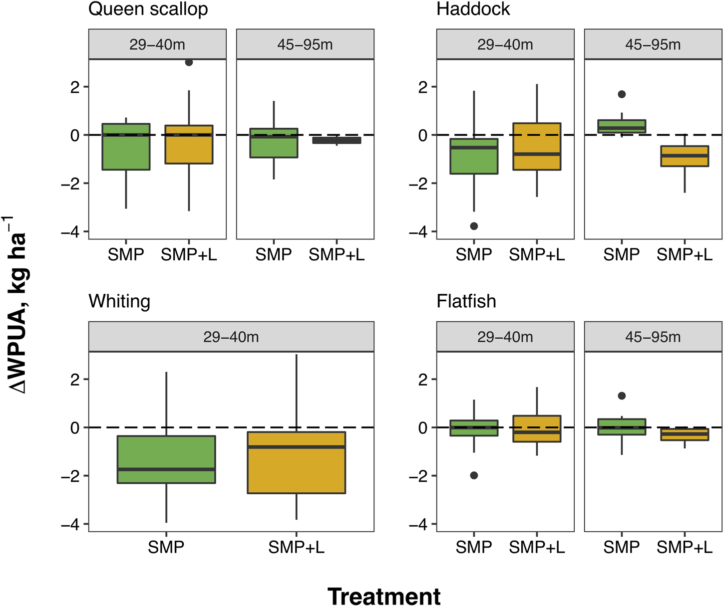
The total catch of Queen scallop (A. opercularis; QSC) throughout the trial was 125 bags weighing ~4375 kg (shallow site: 82; deep site: 43). No significant change in the relative WPUA of marketable QSC caught in the treatment nets was detected, at both sites, compared with the control net (Figure 3; Shallow site (29–40 m): Estimate = −0.29, P = 0.22; Deep site (45–95 m): Estimate = −0.15, P = 0.57, Supplementary Tables S3 & S4). The relative WPUA of QSC did not differ between the SMP and SMP+L net in either site, indicating there is no difference in the effectiveness of the treatment nets to retain QSC, with neither treatment significantly reducing target catch (ANOVA Shallow site (29–40 m): P = 0.85; Deep site (45–95 m): P = 0.89; Supplementary Table S5).
The relative catch (lnRR of WPUA, kg ha−1) of QSC, haddock, whiting and flatfish caught in both treatments (SMP and SMP+L) paired tows per site. The horizontal line (0), represents equal catches by weight per unit area between control and treatment nets (i.e. no effect). The median WPUA (lnRR) is indicated by the horizontal line on the boxplot and error bars indicate the 1.5 times inter-quartile range, the dots represent outliers.
There was no effect of variation in the environmental parameters on relative WPUA of QSC caught in the aggregated SMP and SMP+L nets (GLM; Supplementary Table S6).
Bycatch species
Haddock were caught most frequently out of the three quota gadoid species (695 individuals). Whiting were encountered less frequently (172 individuals), with largest catches at the shallow site (25–40 m). Flatfish (dab L. limanada, plaice P. platessa, lemon sole M. kitt; 3018 total) were consistently caught across both sites. Very few cod were caught (53 individuals), which meant no formal analyses could be conducted. However, the data suggest there were no reductions in catch of cod in the shallow site where they were encountered most frequently (Supplementary Table S3).
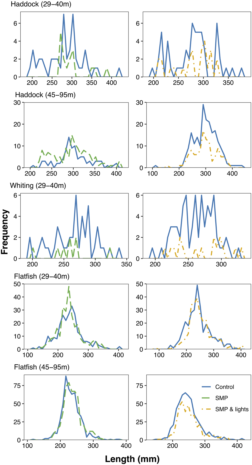
Overall the SMP+L net reduced haddock, whiting and flatfish catches across the majority of size-classes upon inspection of the raw data, with the exception of flatfish in the shallow site, where little change in size frequencies was apparent (Figure 4). The SMP net incurred varied results, with reductions across most sizes in the shallow site for haddock and whiting. While, haddock catches in the deep site (45–95 m) incurred increases across all sizes (Figure 4). However, no change was observed in size frequencies of flatfish caught by the SMP net at the deep site.
Length frequency of catch distributions of haddock, whiting and flatfish plotted per site for both treatments, SMP (left) and SMP+L (right). The blue solid line represents the control net, the green dashed line the SMP and the yellow dashed line the SMP+L net.
At the shallow site (29–40 m), whiting catch per ha was significantly reduced in both the SMP and SMP +L nets by 85% and 75% (both P = 0.01; Supplementary Tables S3 & S4). However, the addition of lights to the panel at these depths had no additional influence on the selectivity of whiting, with no difference in relative WPUA detected between the two treatment nets (ANOVA P = 0.76; Supplementary Table S5). Haddock catches were also reduced in both treatment nets, although, the average reduction of 0.07 kg per ha (58.33%) for both the SMP net and SMP+L was non-significant (Supplementary Tables S3 & S4; SMP: P = 0.05; SMP+L: P = 0.21). Similarily to whiting, the relative WPUA of haddock caught in the SMP net did not differ from that caught in the SMP+L nets in shallow depths (ANOVA P = 0.47; Supplementary Table S5). In shallow water there was no change in relative WPUA of flatfish in either of the treatment nets compared with their paired control tows and the selectivity of the treatment nets did not differ (SMP Estimate = −0.03, P = 0.84; SMP+L Estimate = −0.01, P = 0.98; ANOVA P = 0.91; Supplementary Tables S3–S5).
While fishing in the deep site (45–95 m), the treatment nets produced mixed results. There was no change in WPUA for flatfish in the SMP net relative to the control net (Figure 3; Estimate = −0.06, P = 0.79; Supplementary Tables S3 & S4). There was no significant effect of the standard SMP detected for haddock in deeper waters (Figure 3; Estimate = 0.47, P = 0.06; Supplementary Tables S3 & S4). Conversely, a significant effect was achieved by adding the LED lights, reducing flatfish WPUA by ~26% (Figure 3; Estimate = −0.34, P = 0.01) and haddock by ~47% (Estimate = −0.94, P = 0.004; Supplementary Tables S3 & S4). The relative catch of haddock WPUA in the SMP net differed significantly to the SMP+L (ANOVA P < 0.001), while there was no difference when comparing the relative WPUA of flatfish between treatments (ANOVA P = 0.13; Supplementary Table S5). These results indicate that adding light to the SMP reduced the retention of haddock in deep water.
Only depth explained any change in the catch WPUA of haddock, and none of the other species were affected by variation in the environmental variables (GLM Estimate = −1.49, P = 0.01; Supplementary Table S6).
Discussion
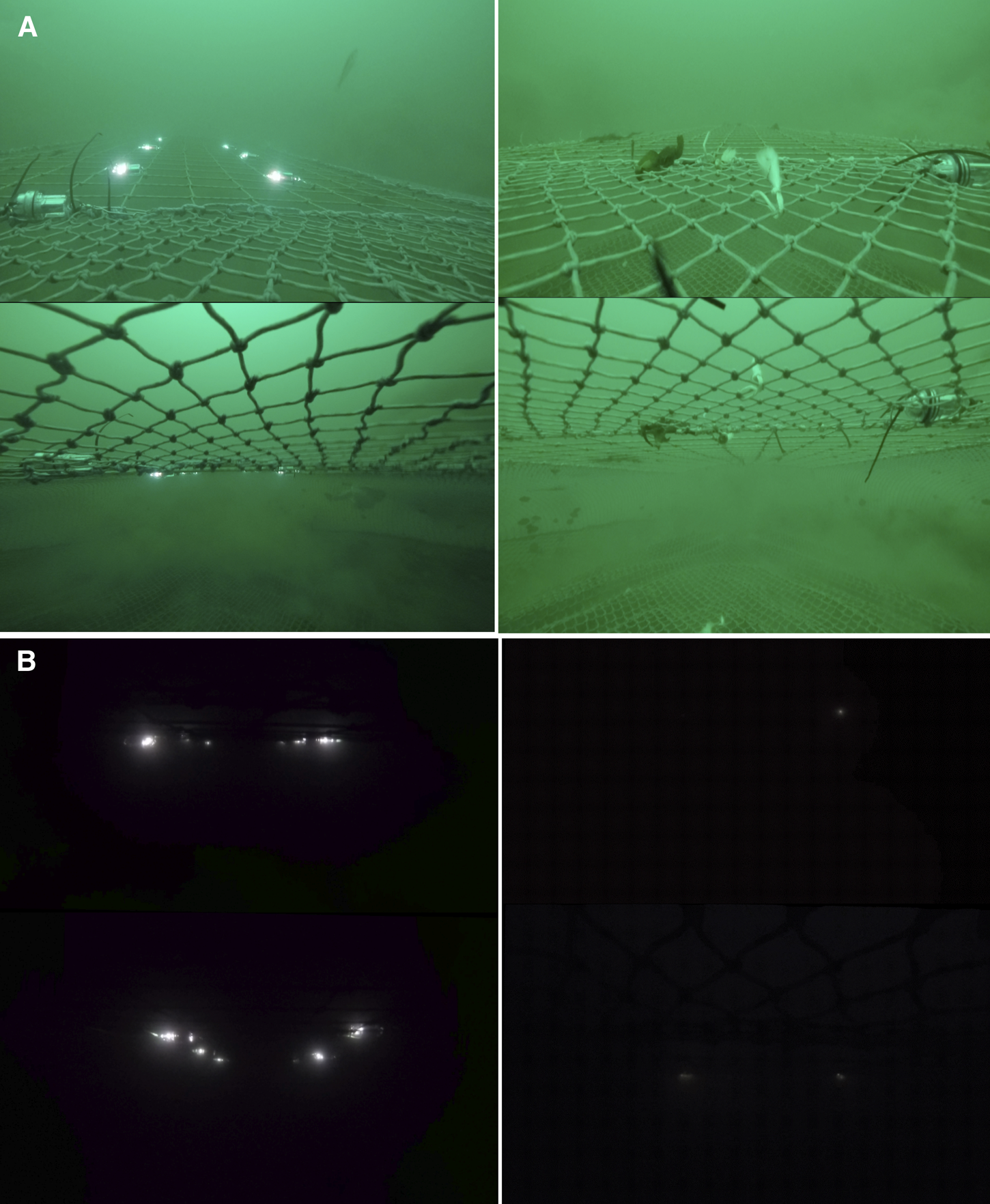
The weight per unit area of all bycatch species caught in the modified nets was lower compared with the traditional control nets, with no significant losses of the marketable Queen scallop (A. opercularis). Reductions were observed for the numbers of haddock (M. aeglefinus), whiting (M. merlangus) and flatfish (dab L. limanda, plaice P. platessa, lemon sole M. kitt) retained in the modified nets. However, the results demonstrated that the effectiveness of the BRDs was context specific. For instance, the SMP+L net only reduced haddock and flatfish bycatch in deeper water, which may be related to associated lower levels of ambient light affecting fish swimming behaviour (Ferro et al., Reference Ferro, Jones, Kynoch, Fryer and Buckett2007) (illustrated in Figure 5). The addition of lights in deep water presumably either guided the haddock towards the SMP or encouraged them to escape through it for another reason (e.g. fright stimulus).
GoPro stills illustrating the visible difference in ambient light levels between sites/depths in (a) Shallow site (30–34 m) SMP+L (left), SMP (right); and (b) Deep site (45–95 m) SMP+L (left), SMP (right). The images show the view looking aft in the net towards the codend from the outside of the net (top image) and the inside of the net (bottom image). Note the long cable ties in the foreground are related to the lights sensor that was fitted to both nets 100% of the time.
Vision is thought to be the primary sense that fish use to detect oncoming nets. When light levels are low, gadoids are incapable of both swimming in an ordered pattern in front of a trawl and locating the gear to avoid collisions, in contrast to behaviour observed at higher light levels (Glass & Wardle, Reference Glass and Wardle1989). This presumably explains why there was no reduction in the WPUA of haddock caught in deeper water >45 m with the SMP treatment (Figure 3).
Low haddock and whiting catches may have reduced the statistical power to detect reductions of haddock catch in the SMP in the shallow site, despite our paired control–treatment design. In addition, the low abundance of fish may have inhibited gadoid escape, as schooling behaviour is induced when lots of fish aggregate in the codend, stimulating an escape response (Broadhurst & Kennelly, Reference Broadhurst and Kennelly1996; Broadhurst et al., Reference Broadhurst, Kennelly and Gray2002). The swimming behaviour of cod (G. morhua) may have inhibited their escapement. Previous studies have found that whereas whiting and haddock rise up in the net and actively locate escape gaps, cod tend to remain low in the net and tend to drift past escape panels located in the upper panel of nets (Krag et al., Reference Krag, Holst and Madsen2009; Herrmann et al., Reference Herrmann, Wienbeck, Karlsen, Stepputtis, Dahmn and Moderhak2015). It should also be noted that the cable ties used to attach the LED lights were trimmed with the purpose of reducing any behavioural stimulus that might be associated with them (Figure 2D). However, cable ties could not be trimmed on some tows due to time limitations, and on these occasions we cannot rule out the possibility that they had a separate effect on the behaviour of fish in addition to the lights. However, as this only occurred on two out of 30 SMP+L replicate tows we consider this possibility was minor.
Additional net modifications could help to reduce bycatch further because the escapement of fish (cod, haddock and whiting) increases as the distance between the SMP and the aft of the codend decreases (Broadhurst et al., Reference Broadhurst, Kennelly and Gray2002; Graham et al., Reference Graham, Kynoch and Fryer2003; Herrmann et al., Reference Herrmann, Wienbeck, Karlsen, Stepputtis, Dahmn and Moderhak2015). Positioning of the SMP was limited in the QSC trawls due to the large SMP relative to net size (~3.5 m from aft of the codend; Figure 2). However, if the SMP was reduced in size and placed as close as possible to the codend without the risk of losing QSC, both water flow and distance from the SMP to the codend would be reduced (Broadhurst et al., Reference Broadhurst, Kennelly and Gray2002; Campbell et al., Reference Campbell, Harcus, Weirman, Fryer, Kynoch and Neill2010). Furthermore, aids such as mechanical guiding devices (i.e. float ropes) require further investigation, as they may also help increase escapement of species that remain low in the net e.g. cod (Grimaldo et al., Reference Grimaldo, Sisitiaga, Herrmann, Larsen, Brinkhof and Tatone2017; Melli et al., Reference Melli, Krag, Herrmann and Karlsen2018).
The reductions of fish bycatch did not appear to be size-dependent, which implies that both large and small individuals were capable of escape. Such similar size distributions may arise because the SMP in this study was designed to allow escapement of a range of individual sizes, which here spanned 100–450 mm. Although bycatch size frequencies were not statistically analysed due to low sample sizes of individual tows, other fisheries use SMPs which are size selective (Brčić et al., Reference Brčić, Herrmann and Sala2016; Fryer et al., Reference Fryer, O'Neill and Edridge2016). Therefore, the effect of BRDs and artificial lights on size selectivity is important to consider in future research. Such studies may be particularly important for fisheries with higher bycatch levels, and where catches must adhere to MLS whilst maintaining commercially sized individuals.
Square mesh has previously shown little change in the selectivity of flatfish (Van Marlen, Reference Van Marlen2003; Krag et al., Reference Krag, Holst and Madsen2009). However, this study demonstrated that the addition of LEDs fitted to the SMP has the potential to reduce fish capture of various shapes and sizes, including haddock and, unexpectedly, flatfish. When considering avenues for future gear trials incorporating artificial light, expanding our understanding of the behavioural stimulus lights have on marine species is required for future fisheries applications (Melli et al., Reference Melli, Krag, Herrmann and Karlsen2018). It is suggested that LEDs attached to the mouth of the net (to deter species from entering or enable species to detect the approaching net), could potentially reduce the capture of various species, including individuals that are unlikely to escape through the SMP, which has previously been a successful strategy for reducing fish bycatch in ocean shrimp trawls (Hannah et al., Reference Hannah, Lomeli and Jones2015; Lomeli et al., Reference Lomeli, Groth, Blume, Herrmann and Wakefield2018b). Using LEDs alone would be a simple, cheap solution, involving minimal alterations to fishing gear. LEDs can be implemented in small- and large-scale fisheries and are not restricted to certain gear types, and could prove beneficial in reducing multi-taxa bycatch in fisheries operating at night or in dark waters (Hannah et al., Reference Hannah, Lomeli and Jones2015; Ortiz et al., Reference Ortiz, Mangel, Wang, Alfaro-Shigueto, Pingo, Jimenez, Suarez, Swimmer, Carvalho and Godley2016; Mangel et al., Reference Mangel, Wang, Alfaro-, Pingo, Jimenez, Swimmer and Godley2018). A video capturing bycatch escapement through the SMP+L net is provided in the supplementary material (Supplementary Video S7).
To conclude, for BRDs, one size does not fit all; this study demonstrates the importance of assessing and implementing BRDs on a site-by-site basis within a fishery, as environmental parameters change over small spatial scales, which may influence the ability of the devices to reduce bycatch.
Supplementary material
The supplementary material for this article can be found at https://doi.org/10.1017/S0025315420000028
Acknowledgements
We are grateful to the skippers and crew of FVs ‘Our Sarah Jane’ and ‘Two Girls’ for their assistance on board the vessels. We especially thank our colleagues Sian Morgan and Claire Lambden for their valuable help at sea, our sponsors at SafetyNetTechnologies Ltd and the Manx Fish Producer's Organisation for their technical support and insight during the gear trials. We thank three anonymous reviewers for their insightful comments that greatly improved the study.
Financial support
This study was supported by the Manx Fish Producer's Organisation and Department for Environment, Forestry and Agriculture, Isle of Man Government.


