


Introduction
Since electromagnetic band gap (EBG) structures have been presented in the last two decades, they have been extensively applied in different antenna applications. EBG has a high-impedance surface that mainly suppresses surface waves in microwave circuits and antennas [Reference Yang and Rahmat-Samii1]. The basic type of EBG is the mushroom-like structure whose periodic length equals to a half wavelength. Several modifications have been applied to the typical mushroom-like EBG to introduce size miniaturization either by modifying EBG traditional geometry [Reference Mingyan, Zhenghe, Fanglu, Li and Jingzhao2–Reference Mohammadi, Ellis, Ghahremani, Alizadeh, Nourinia and Ghobadi6] or by loading it with other resonators (can introduce multi-bands as well) [Reference Peng, Ruan and Li7–Reference Vendik, Rusakov, Kanjanasit, Hong and Filonov12]. However, single, dual, or even triple notch bands can be obtained by introducing stubs beside or under the microstrip lines [Reference Li, Tu, Chu and Wu13, Reference Liu and Tu14] and etching slits in the radiating patches [Reference Hosseini, Hassani and Amini15–Reference Wu, Xi, Hu, Tang, Zhan and Liu17] or in the ground plane [Reference Kang, Li, Wang and Shi18, Reference Rehman and Alkanhal19] and the room is still open to further modifications.
The Federal Communication Commission has assigned the frequency bands 3.1–10.6 GHz for high data rate/short pulse wireless services [Reference Abdelraheem and Abdalla20, Reference Chandel, Gautam and Kanaujia21]. This band is interfered by different WiMAX services at 3.5 /5.2/5.8 GHz. Different interference suppression techniques with successful application of EBG for multi-band interference notching are is introduced [Reference Yazdi and Komjani22–Reference Feng, Chung, Lai and Zeng30]. One of the main challenges in the suppression technique is high selectivity (notching the interference without affecting the main frequency band radiation) [Reference Abdalla, Al-Mohamadi and Mostafa31].
In this paper, the detailed design, analysis, and measurements of a miniaturized mushroom-like EBG unit cell with dual-band gaps are introduced. The suggested configuration is based on loading the typical mushroom with two inverted U-shaped slots beside the via in the center of each unit cell. The structure has become a dual-band notch filter. Next, the designed cell is applied to a typical elliptical monopole antenna to have a very sharp notching at 5.2 and 5.8 GHz with almost 100 MHz notch bandwidth.
EBG design motivation
The conventional mushroom-like electromagnetic band gap structure shown in Fig. 1(a), printed on a substrate of thickness (h) is equivalent to a parallel LC network such that the inductor L is due to the currents flowing through the vias and the capacitor C is due to the gap between the adjacent patches (g) as illustrated in Fig. 1(b). The band stop center frequency (f c) can be calculated as in [Reference Peng, Ruan and Xiong8]:
 $$f_c\, = \,\displaystyle{1 \over {2\pi \sqrt {LC}}} $$
 $$L\, = \,2L_1\, = \,2\mu _0h$$
 $$C\, = \,W_e\varepsilon _0\,\displaystyle{{(\varepsilon _r + 1)} \over \pi} \,\cosh ^{-1}\,\left( {\displaystyle{{W_e + g} \over g}\,} \right)$$
The mushroom-like EBG: (a) its 2D configuration and (b) its equivalent circuit; the modified mushroom-like EBG: (c) the 2D configuration (W e2 × W e2 = 4.45 × 4.45 mm2, d = 0.5 mm, g 1 = 0.4 mm, w u = 2.25 mm, and l u = 2.85 mm) and (d) the equivalent circuit.

As a case study, which will be used as a reference in our work later in the paper, a mushroom-like EBG was designed to have a band-stop at 5.5 GHz. The cell has W e = W e1 = 8.2 mm on a Rogers RO4003 substrate with a relative permittivity of 3.55 and a thickness of 0.813 mm. The periodic gap between EBG particles is g = 0.4 mm. For a validation point of view, it can be checked using (2) that the inductance L is 2.1 nH and using (3) to have a capacitance of 0.45 pF. Hence in (1), the band-stop frequency can be calculated to be 5.5 GHz.
In order to have new EBG with dual-stop band functionality, its equivalent circuit should have become a dual-stop filter. Therefore, the proposed new configuration for a dual-band EBG cell is shown in Fig. 1(c). It is inspired from having a band-stop filter from a defected ground structure in microstrip lines. The cell was suggested to use a double-inverted U-shaped slot within the main conductor of the EBG cell. The objectives of the U shape are to increase the length of the slot within a small physical size whereas the inverted shape is oriented to reduce the mutual coupling between the slots for a simple design.
The new EBG equivalent circuit is shown in Fig. 1(d) where a second order band-stop resonator can lead to dual-notch frequencies. The dimensions of the new EBG unit cell are 4.5 × 4.5 mm2. The design for the two resonance frequencies (initial values) (f c1 = 5.8 GHz, f c2 = 5.2 GHz) can be retrieved using (4) and (5):
 $$f_{c1}\, = \,\displaystyle{1 \over {2\pi \sqrt {L_1C_1}}} $$
 $$\; f_{c2}\, = \,\displaystyle{1 \over {2\pi \sqrt {L_2C_2}}} $$
Hence, in (3), C 1 is 0.27 pF. The U-shaped slot has C 2 = 2 pF and L 2 = 0.5 nH. Therefore, in comparison with conventional single band mushroom-like EBG one (8.2 × 8.2 mm2), the modified EBG size has become 70% smaller.
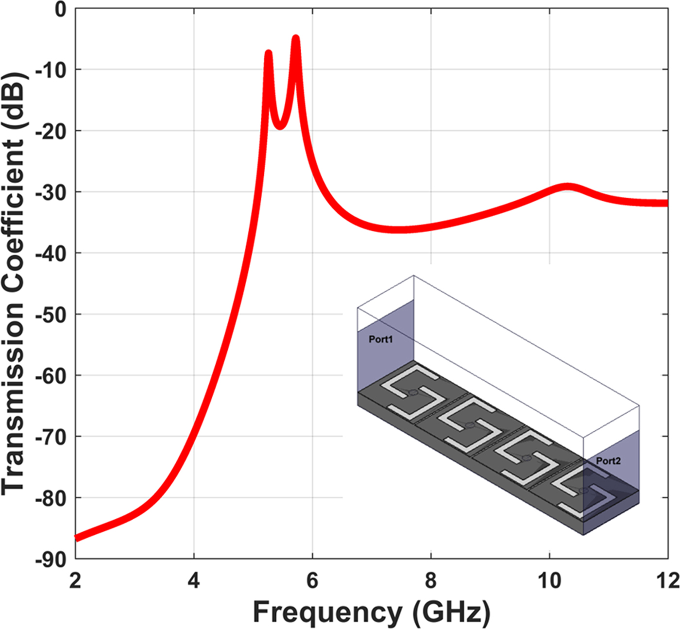
To confirm the homogeneous medium nature of the proposed EBG unit cell, which will cancel any confusion that the effect of the added EBG pattern, is acting as cutting a slot in patch antennas, the propagation through many proposed EBG cells had to be studied. Accordingly, the modified EBG cell is characterized by the exciting periodic structure of four unit cells through its longitudinal axis and checking the resonance by studying the transmission coefficient S 21 at the feeding terminals as shown in Fig. 2. The simulated transmission coefficient (S 21) values demonstrate a high-quality dual band resonance at 5.2 and 5.8 GHz; before/after that, S 21 drops to less than −20 dB in less than 100 MHz (high resonator quality factor). A comparison between the modified cell and recent miniaturized EBG is summarized in Table 1.
The simulated transmission coefficient (S 21) from four periodic unit cells of the modified EBG cell.
A comparison between recent miniaturized EBG cells
Antenna structure and design
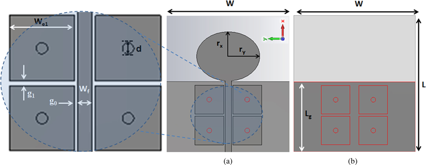
To demonstrate the advantage of the proposed UWB dual-notch antenna, a typical UWB notch antenna is presented as a reference. The reference antenna is an elliptical UWB monopole with a single notch using conventional mushroom-like EBG structures. The reference antenna layout (top and bottom) views are shown in Fig. 3. As shown in Fig. 3(a), high notching four conventional mushroom EBG cells are coupled to the antenna on the same top layer with the dimensions for the 50 Ω feeding transmission line (W f). The coupling distance between the EBG cells and the feeding line is g 0, and the length of the square side length of the EBG cell with the diameter of the via, and the gap distance between the mushroom cells are w e1, d, and g 1, respectively. The transparent bottom layer (ground plane) with red lines illustrates the corresponding position for the EBG cells on the top layer of the UWB monopole antenna and their vias connecting them to the ground (Fig. 3(b)). The used substrate is the same as that used in the above case studies (Rogers RO4003) with length L and width W, while the ground plane has length L g but with the same width of the substrate.
The reference elliptical monopole antenna with typical mushroom-like EBG: (a) the top view, (b) the bottom view; dimensions: W = 35 mm, L = 39 mm, r x = 7 mm, r y = 9 mm, W f = 1.8 mm, L g = 17.8 mm, W e1 = 8.2 mm, d = 1.4 mm, g 0 = 0.4 mm, and g 1 = 0.6 mm.
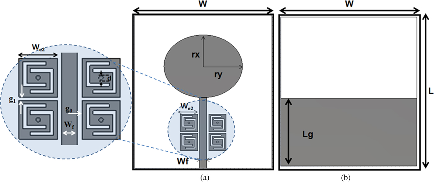
To introduce UWB radiation with a dual notch at 5.2 and 5.8 GHz, it is proposed loading the elliptical monopole antenna with the modified mushroom-like EBG cells. Similarly to the reference antenna, the new antenna has four modified mushroom-like EBG cells which are placed parallel to the antenna microstrip feeding line. The proposed antenna is shown in Fig. 4; both top and bottom layers are shown in Fig. 4(a) and Fig. 4(b), respectively, with dimensions for the proposed antenna and modified mushroom-like EBG cells. The dimensions of the U-shaped slots (l u and w u) are shown in the figure, and the slots are etched with 0.4 mm width, both the square side length and the diameter of the vias decreased.
The UWB elliptical monopole antenna loaded with modified mushroom-like EBG cells: (a) top view, (b) bottom view; W e2 = 4.45 mm, d = 0.5 mm, g 0 = 0.5 mm, g 1 = 0.4, w u = 2.25 mm, and l u = 2.85 mm.
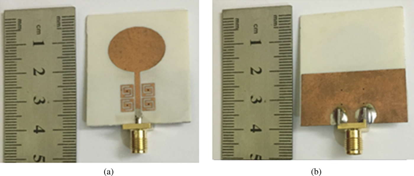
The proposed UWB dual-notch antenna is fabricated as shown in Figs 5(a) and 5(b) for the top and bottom views, respectively. It can be observed that the modified EBG cell size area has become 4.45 × 4.45 mm2 instead of 8.2 × 8.2 mm2, which represents 70.55% miniaturization of the conventional EBG cell size area.
The fabricated UWB dual-notch antenna prototype: (a) the top view and (b) the bottom view.
The simulated reflection coefficient of the modified UWB dual-notch antenna is shown in Fig. 6 compared with the single reference notch UWB antenna. As it is noticed, the reference antenna has a wideband associated with a reflection coefficient less than −6 dB over the bandwidth of 3.1–12 GHz except at notch frequency. At notch frequency (5.45 GHz), the reflection coefficient is almost −0.25 dB; no radiation. The 3 dB notch bandwidth is from 5.27 to 5.65 GHz (fractional bandwidth = 7%), while in the case of modified antenna, it has lower than −10 dB reflection coefficient over the UWB frequency band except at the two notch frequencies 5.2 and 5.85 GHz; however, some small frequency shifts are noticed in the modified antenna.
The simulated reflection coefficient of the reference UWB single notch using typical mushroom-like EBG and the modified UWB dual-notch antenna using the dual slot mushroom-like EBG.

The modified antenna has a dual high reflection coefficient at 5.2 GHz (close to −2 dB) and 5.85 GHz (−1 dB). From the previous comparison of simulated values of the reference antenna, it was confirmed that the proposed antenna has a dual-band functionality and a high selective property. In other words, before/after each of the two center frequencies, the reflection coefficient drops to less than −10 dB at 5.1/5.3 GHz in the first band and 5.75/6.15 GHz in the second band. These values can reveal the high selectivity of the notch filtering especially in between the two notch frequencies. In other words, the proposed antenna has dual notching with switching between radiation and non-radiation mechanism in only 100 MHz around the antenna notch frequency.
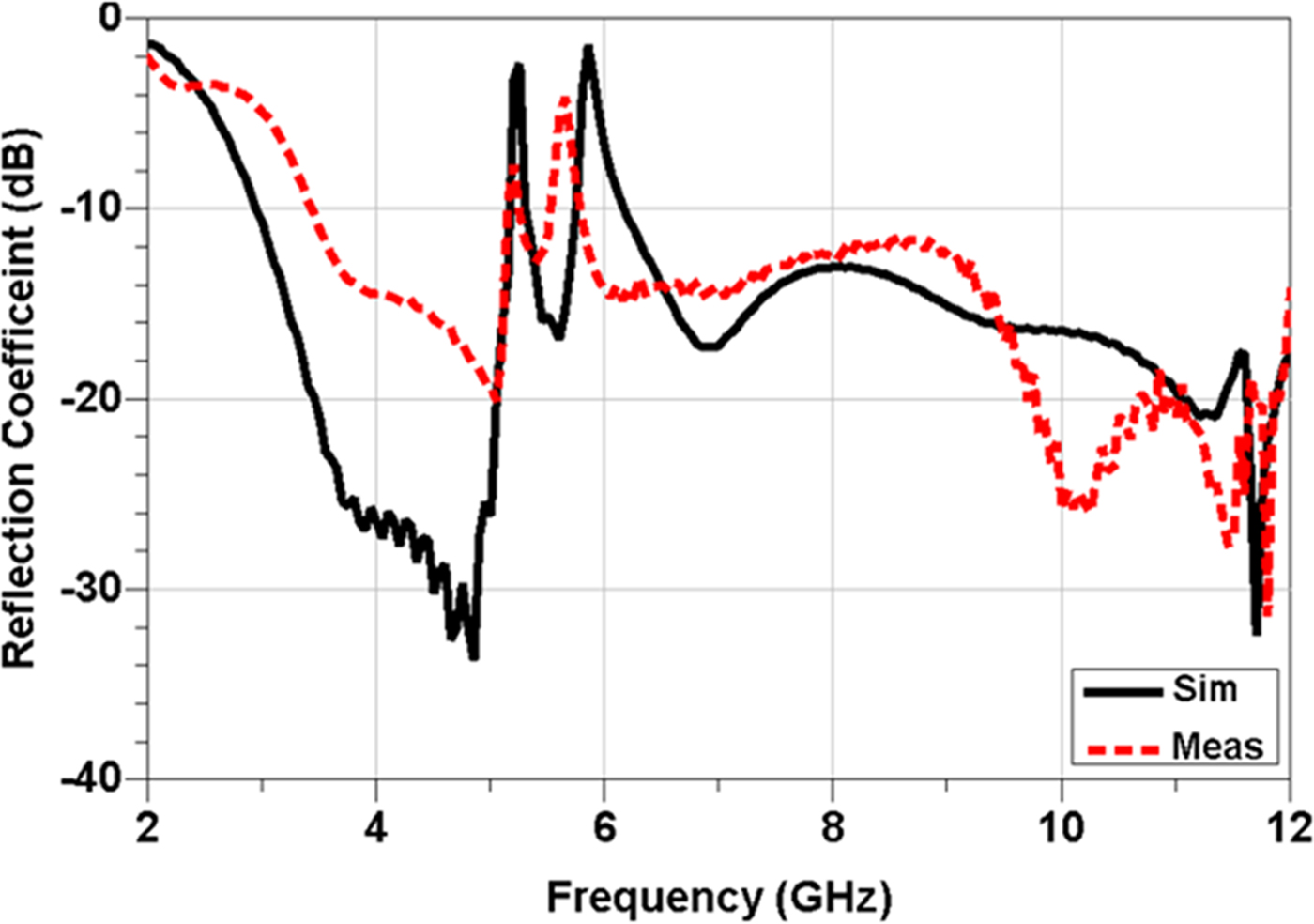
The simulated and measured reflection coefficient of the antenna is shown in Fig. 7. Although, the measured results are slightly lower than the simulated values, this was claimed due to non-avoidable imperfection at fabrication. However, the dual band/high selectivity phenomena are still valid.
The simulated/measured reflection coefficient of the modified UWB dual-notch antenna.
Dual-notch antenna analysis and discussion
Antenna current distribution
The simulated current distribution of the proposed UWB dual-notch antenna is shown in Figs 8(a) and 8(b) at 5.2 and 5.85 GHz, respectively. It is obvious that at these frequencies, the proposed new four EBG cells have trapped the feeding current and prevented it from passing to the elliptical monopole radiator. In terms of current levels, almost no current is passing to the radiators at the two frequencies. This explains the previously achieved reflection coefficient (close to −1 dB) at these frequencies as shown in Fig. 6; also, the results of the dual high reflection coefficient at both 5.2/5.85 GHz for both cases of simulation and measurement have a good matching as shown in Fig. 8.
The simulated current distribution along the UWB dual-notch antenna at (a) 5.2 GHz and (b) 5.8 GHz.

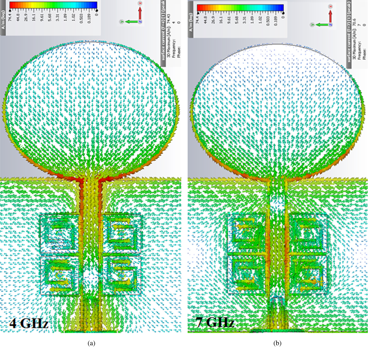
To confirm this phenomenon, the current distributions are plotted in Fig. 9 at two radiating frequencies (4 and 7 GHz). These frequencies were selected outside the notch bands to confirm the good radiation of the antenna; EBG does not affect antenna performance. It is evident in both cases; the new EBG has small current distribution through it. This conclusion confirms the good matching reflection coefficient outside the notch frequency band in the proposed antenna.
The simulated current distribution along the UWB dual-notch antenna at (a) 4 GHz and (b) 7 GHz.
Radiation pattern
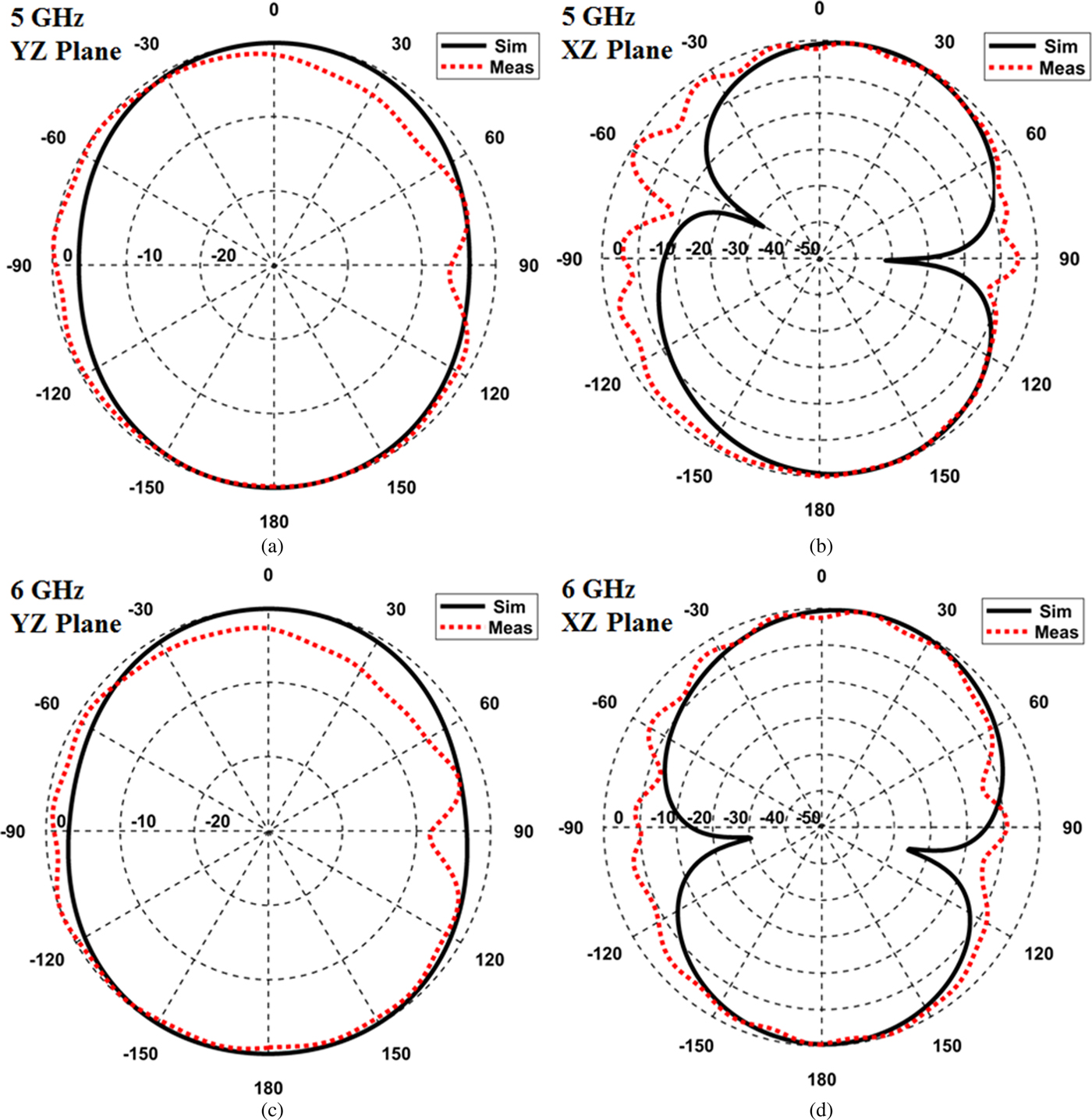
The radiation patterns of the proposed antenna outside/inside the notch frequency bands are emphasized in this section. To confirm the good selectivity and good radiation of the proposed antenna, the simulated 3D radiation patterns of the antenna at 5 and 6 GHz (only 200 MHz outside the center notch frequency for further confirmation) are plotted in Figs 10(a) and 10(b), respectively. The antenna pattern is very close to typical monopole omnidirectional radiation one with a gain of 3.58 dB at 5 GHz and 2.07 dB at 6 GHz. On the other hand, at 5.2 and 5.8 GHz, the simulated 3D radiation patterns (in Figs 10(c) and 10(d), respectively) demonstrate very poor radiation with gain almost 0 dB. Further validation of the antenna radiation performance is achieved by comparing the simulated and measured radiation patterns in both E (XZ) and H (YZ) planes as shown in Fig. 11. As shown in the figure, the typical omnidirectional radiation pattern is almost validated.
The simulated 3D gain radiation pattern of the UWB dual-notch antenna at (a) 5 GHz, (b) 6 GHz, (c) 5.2 GHz, and (d) 5.8 GHz.

The measured and simulated radiation patterns of the UWB dual-notch antenna at (a) 5 GHz (YZ plane), (b) 5 GHz (XZ plane), (c) 6 GHz (YZ plane), and (d) 6 GHz (XZ plane).
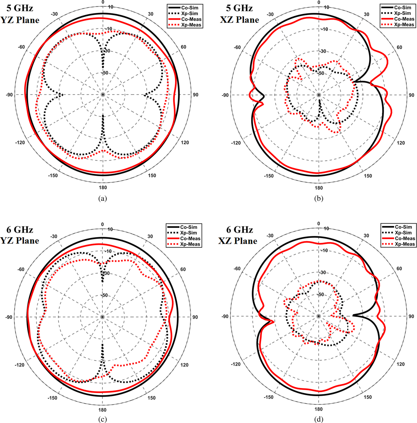
The linearity of the dual-notch UWB antenna is validated in Fig. 12, where the difference between co-polarized (CP) and cross-polarized (XP) gains in the YZ-planes is shown in Figs 12(a) and 12(c) at 5 and 6 GHz, respectively. The simulation results have differences between CP and XP components. These differences range from 5 to more than 20 dB, at the boresight angle as in the ideal case. However, the measurements difference in the YZ plane is only 5 dB which can be claimed due to non-avoided imperfections in fabrication/measurements. For the XZ-plane results, shown in Figs 12(b) and 12(d), the difference level is more than that in the YZ-plane especially at the boresight angles with 15 dB for both simulated and measured results. Therefore, the difference level for CP and XP gains in the XZ-plane at 5 or 6 GHz is 20 dB.
The measurement and simulation of CP and XP gains at (a) 5 GHz (YZ plane), (b) 5 GHz (XZ plane), (c) 6 GHz (YZ plane), and (d) 6 GHz (XZ plane).
Finally, the simulated maximum gain of the antenna is plotted versus frequency in Fig. 13 where it is clear that the antenna has an average gain = 4 dB except at the notch frequencies where it drops to 0 dB. It is noted that the high selectivity feature of the reflection coefficient in Fig. 8 is also validated in the gain. As it is noticed the gain between the dual-notch frequencies is around 2.5 dB which is enough between two narrowly separated highly selective notch frequencies. If more gain is needed in such a case, the two selective notch frequencies have to be further from each other to prevent overlapping filtering effect, so 2.5 dB is considered fair enough to be achieved in such case.
The simulated UWB dual-notch antenna gain versus frequency.

Conclusion
A new high selective dual band EBG cell is introduced and investigated. The cell has been applied to dual notching of UWB antennas to eliminate the possible interference of WLAN frequencies at 5.2 and 5.8 GHz bands. The proposed cell is 70% small in size compared with conventional mushroom-like EBG. Enough difference level between the CP and XP gains (to guarantee a linear antenna) has obtained. Moreover, it has dual-band functionality. Within only 100 MHz from the center of the notch frequency, the proposed antenna restores its good radiation with average antenna gain = 4 dB over the ultra-wide operating frequency band and 0 dB at the notch frequencies also, with a fair gain value in the region between the dual-notch frequencies due to the overlapping of the dual filtering responses.
Author ORCIDs
Mahmoud A. Abdalla, 0000-0001-6759-7268
 Dr. Mahmoud A. Abdalla was born in 1973. He received the B.Sc. and M.Sc. Degrees in electrical engineering from the Electrical Engineering Department, Military Technical College, Cairo, Egypt in 1995 and 2000. He received the PhD degree from School of Electrical Engineering, University of Manchester, UK, in 2009. He is now an associated professor and head of electromagnetic waves group in Electronic Engineering Department, Military Technical College. Dr. Mahmoud was the recipient of Egyptian encouragement state prize for engineering sciences in 2014. He published more than 180 peer-reviewed journal and conference papers. His research has focused on miniaturized, multiband and wideband microwave/ millimeter antennas. Components and absorbing materials with great attention is to employ metamaterial / EBG, structures. Dr. Mahmoud Abdalla is a senior member of the IEEE and the European Microwave Association EuMA. He is currently a reviewer in many high ranked electromagnetic journals.


