


Introduction
One of the key enabling technologies for the fifth generation (5G) of mobile systems is the use of millimeter-wave (mm-wave) frequency bands to deliver broadband Internet access in cellular networks [Reference Wang, Li, Huang, Jing, Georgakopoulos and Demestichas1]. The broader spectrum range available at the 5G mm-wave bands (such as the 28, 39, and 60 GHz bands) makes it possible to achieve higher data rates, higher system capacity, and lower latency than previous generations of mobile systems working at frequencies below 6 GHz [Reference Hong, Jiang, Yu, Hou, Wang, Guo, Hu, Kuai, Yu, Jiang, Chen, Chen, Yu, Zhai, Zhang, Tian, Wu, Yang, Hao and Zhou2, Reference Rappaport, Xing, MacCartney, Molisch, Mellios and Zhang3]. A close consideration has been given to the signal propagation conditions in the mm-wave bands, which are more adverse than those in the sub-6 GHz bands, due to the higher path loss and larger sensitivity to blockage [Reference Rappaport, Xing, MacCartney, Molisch, Mellios and Zhang3, Reference Salous, Degli-Esposti, Fuschini, Thomae, Mueller, Dupleich, Haneda, Molina-Garcia-Pardo, Pascual-Garcia, Gaillot, Hur and Nekovee4]. In outdoor scenarios, the presence of high buildings or other structures in the surroundings of a 5G base station (BS) may result in blind zones (with poor coverage) [Reference Zheng, Wang, Han, Zhao and Wang5]. In the case of indoor scenarios, walls and glass panels can easily block mm-wave signals, producing link instability and coverage problems if the mobile users are not in direct line of sight from the BS [Reference MacCartney, Rappaport, Sun and Deng6].
In the last few years, the so-called intelligent reflecting surfaces (IRSs) have been identified as a promising solution to overcome coverage problems and improve the performance of mm-wave 5G networks [Reference Wu and Zhang7, Reference Wang, Fang, Yuan, Chen and Li8]. An IRS is formed by a planar array of reflecting cells, which can be independently designed to control the phase and/or the amplitude of the reflected wave. The IRS does not perform any active processing of the incident signals before reflecting them, so they can be massively deployed at reduced cost, with low-energy consumption (if the IRS is completely passive, it does not require any energy consumption), and low environmental impact (fixed on walls, thanks to their flat surface). Recent works [Reference Wang, Fang, Yuan, Chen and Li8, Reference Björnson and Sanguinetti9] have confirmed the positive impact of the IRS in the network performance at a system level; however, there are very few works in the literature about practical implementations of IRS for 5G [Reference Pei, Yin, Tan, Cao, Li, Wang, Zhang and Björnson10].
Reflectarray antennas [Reference Huang and Encinar11] have been recently proposed for several 5G applications at mm-wave bands. These applications comprise steerable-beam antennas [Reference Mei, Zhang and Pedersen12, Reference Yu, Zhang, He, Gao, Chen and Zhu13] and fixed-beam antennas [Reference Costanzo, Venneri, Borgia and Massa14–Reference Wang, Fang and Liu16] for BSs and point-to-point links, and terminal antennas for connected vehicles [Reference Zhang, Zhang, He, Mao, Li, Wong, Mei and Gao17]. In all the previous works, the reflectarrays are designed to produce a pencil beam, using an illuminating feed-horn located close to the reflectarray surface (the focal length-to-diameter ratio, F/D, is between 0.5 and 1.5). In this paper, the authors propose the use of reflectarrays to implement passive IRSs to enhance wireless coverage in mm-wave 5G systems, exploiting their capabilities to generate shaped beams [Reference Arrebola, Encinar and Barba18, Reference Zhou, Sørensen, Kim, Jørgensen, Meincke and Breinbjerg19] and to operate in dual polarization [Reference Costanzo, Venneri, Borgia and Massa14, Reference Florencio, Encinar, Boix, Losada and Toso20]. Passive IRSs based on reflectarray panels can be produced at a lower cost than shaped-metallic reflectors and phased arrays, thanks to their simple fabrication by the same techniques and processes used for multi-layer printed circuits. Moreover, the flat profile and lightweight of reflectarrays allow for simple installation on the walls or ceilings, minimizing the visual impact. This technology has been key in the development of the KLONE passive reflector from Metawave Inc. [Reference Ozdemir, Erden, Guvenc, Yekan and Zarian21].
Compared to previous works on reflectarrays for 5G applications [Reference Mei, Zhang and Pedersen12–Reference Zhang, Zhang, He, Mao, Li, Wong, Mei and Gao17], the design of reflectarray-based IRSs involves some particular aspects that must be carefully addressed. First, the reflectarray must be designed to produce a shaped beam (instead of a pencil beam) that matches the coverage specifications of the scenario, in order to concentrate the power received from the BS in a specific area. By means of a proper phase-only synthesis (POS) technique [Reference Prado, Arrebola, Pino and Las-Heras22, Reference Niccolai, Zich, Beccaria and Pirinoli23], the reflectarray can be designed to change the direction of the reflected wave and produce a specific shape of the beam, according to the scenario requirements. Second, the reflectarray panel will be illuminated from a 5G BS, which can be located at a significant distance from the reflectarray (e.g. between 10 and 100 m). Due to the geometry of the scenario, the reflectarray elements can be illuminated with large incidence angles from the BS (in contrast to previous works [Reference Mei, Zhang and Pedersen12–Reference Zhang, Zhang, He, Mao, Li, Wong, Mei and Gao17] with centered or slightly offset close feeds, which lead to lower incidence angles). This factor must be taken into account in the design of the reflectarray cells, since the cells must be able to provide a satisfactory performance under strong oblique incidence. The last challenge is related to the large number of cells that form the IRS, which may result in more complex analysis and design processes of the reflectarray.
In this paper, two 800 mm × 400 mm reflectarray panels (KLONES) have been designed to improve 5G mm-wave coverage in the 28 GHz band in an outdoor scenario, acting as passive IRS. The reflectarray panels generate broadened and deflected beams in dual-linear polarization (horizontal and vertical) with different incident and reflecting angles. The radiation patterns of both reflectarrays show a stable performance in the 27.2–28.2 GHz band, with low levels of side-lobes and cross-polarization, in spite of the high incidence angles from the BS (around 50° in both cases). Note that the concept of reflectarray-based IRS for 5G was first introduced by the authors in [Reference Martinez-de-Rioja, Vaquero, Arrebola, Carrasco, Encinar and Achour24], including some preliminary results for a conventional scenario. In this paper, several valuable contributions are introduced with respect to [Reference Martinez-de-Rioja, Vaquero, Arrebola, Carrasco, Encinar and Achour24]. First, a more complex application scenario involving the design of two reflectarray panels is considered, with different coverage requirements for each reflectarray. Second, an in-depth analysis of the operating principle and performance of the reflectarray cell is provided (angular stability, independent phase control in each polarization, etc.), including the reasons for selecting the proposed elements instead of other single-layer or multi-layer elements. Then, a detailed description of the POS technique used to produce the shaped beams is given, including the starting point and final results for the synthesis of each reflectarray. Finally, the bandwidth performance of the two reflectarrays is analyzed in detail, considering both linear polarizations.
Description of the outdoor scenario
The reflectarray panels were installed in a conventional outdoor scenario with blind zones, as illustrated in Fig. 1(a). The scenario requirements in terms of beam pointing and half-power beamwidth are shown in Figs 1(b) and 1(c) for KLONE 1 (K1) and in Figs 1(d) and 1(e) for KLONE 2 (K2). The mm-wave BS and K1 are at the same height, separated by a distance of around 40 m and forming an angle of 51° in the azimuth plane. In the case of K2, the incidence angle of the wave coming from the BS is 52° in azimuth and 4.5° in elevation. The size of the reflectarray panels is 800 mm × 400 mm, each panel being composed of 178 × 90 reflectarray cells (more than 16 000 cells per panel).
(a) Outdoor scenario with two reflectarray panels (K1 and K2) installed on the wall and illuminated from a FR2 5G BS. (b, d) Azimuth view and (c, e) elevation view of the outdoor scenario for K1 (b, c) and K2 (d, e).

The two reflectarray panels must be designed to produce a deflected and broadened beam at the 28 GHz band. K1 must radiate a beam at an angle of 51° in the azimuth plane and −18° in the elevation plane with respect to broadside, while the radiation angles for K2 are 52° in azimuth and −4.5° in elevation. Moreover, half-power beamwidths of 5.5° in azimuth and 1.5° in elevation are required in both cases to provide suitable coverage of the blind zones. Note that a pencil-beam reflectarray of the same size (800 mm × 400 mm) would present a half-power beamwidth of around 2° in azimuth and 0.7° in elevation, so the beam has to be widened in both planes to comply with the scenario requirements.
The large distance between the reflectarray panels and the illuminating BS antenna is a typical characteristic of this kind of 5G outdoor scenarios, which is different from conventional configurations of reflectarray antennas with a ratio of focal length to diameter (F/D) between 0.5 and 1.5. Because of the large distance, the incidence angles in spherical coordinates (θi, φi) on the reflectarray cells present minor variations: in the case of K1, θi varies between 50.7 and 51.3°, and the maximum variation of φi is ±0.7° with respect to 90° (note that the x-axis is used as the reference for φi = 0°). Similar variations of (θi, φi) are obtained for K2, where the average values of the incidence angles are θi = 51.9° and φi = 84.5°. This feature allows for a more straightforward design process, as will be explained in the Section “Design process and results.”
Reflectarray cell
The KLONES must be designed to present the same radiation pattern in both horizontal (H) and vertical (V) polarizations, so that the 5G network can achieve polarization diversity. Hence, a dual-polarization reflectarray cell, enabling independent phase control in each linear polarization, is required for the design of both reflectarray panels. The large incidence angles of the scenario (see Fig. 1) can be an obstacle to accomplish this characteristic, since they can deteriorate the performance of the reflectarray cells. To overcome this problem, reflectarray cells with large angular stability must be used.
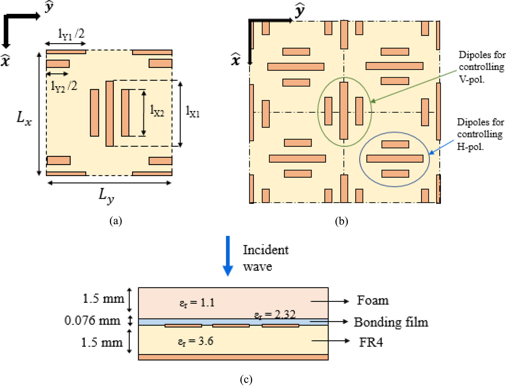
The reflectarray cell used in this work, which is depicted in Fig. 2(a), is formed by orthogonal groups of parallel dipoles, which are arranged parallel to the x-axis or the y-axis of the reflectarray panel in order to control phase shift introduced in V-polarization or H-polarization, respectively. The phase shift required in each polarization can be accomplished by means of a proper adjustment of the lengths of each group of dipoles (lX 1 and lX 2 for V-polarization and lY 1 and lY 2 for H-polarization). The cells are arranged in such a way that the groups of dipoles for H-polarization are shifted half a period along both the x and y axes with respect to the groups of dipoles for V-polarization, see Fig. 2(b). The lateral dipoles of each group present the same length, in order to reduce the levels of the cross-polar components. Figure 2(c) shows the lateral view with the multi-layer configuration of the reflectarray cell. The dielectric substrate on which the dipoles are printed is FR4 (ɛr = 3.6, tan δ = 0.01) of 1.5 mm thickness. Then, the reflectarray panel is covered by a 1.5-mm thick foam sheet (ɛr = 1.1, tan δ = 0.004) which is used to protect the dipoles. The foam is glued to the upper side of the FR4 (with the printed dipoles) by means of a 0.076-mm thick bonding film (ɛr = 2.32, tan δ = 0.003). The performance of the reflectarray cell has been analyzed taking into account the three dielectric layers.
Upper view of (a) the periodic unit cell and (b) the reflectarray periodic structure. (c) Lateral view with the stack-up configuration.
The reflectarray elements selected for the design of the KLONES provide a larger phase variation range and a more linear phase response (with a smoother slope) than other reflectarray cells with simpler configuration (e.g. a rectangular patch [Reference Encinar25]). These characteristics are accomplished even under strong oblique incidence conditions and lead to a broadband performance of the reflectarray panel. The reflectarray cells used in this work provide a similar performance to that of multi-layer reflectarray cells formed by stacked rectangular patches [Reference Florencio, Boix, Losada, Encinar, Carrasco and Arrebola26], with the advantage of using a single layer of printed elements instead of several layers (which reduces the fabrication cost, weight, and volume of the reflectarray antenna). Besides, note that other single-layer reflectarray cells with multi-resonant elements [Reference Chaharmir, Shaker and Legay27, Reference Hasani, Peixeiro, Skrivervik and Perruisseau-Carrier28] have two planes of symmetry, and thus, do not allow us to introduce a different phase shift in each linear polarization, as it is the case of the cell based on orthogonal groups of dipoles that is used in this work.
The unit-cell parameters have been optimized to achieve a linear phase response of the reflection coefficient at 27.7 GHz (center operating frequency of the KLONES). The dimensions of the periodic cell are LX = 4.5 mm and LY = 4.5 mm, which are less than λ/2 at 28 GHz. The width of the dipoles is set to 0.25 mm, and the distance between parallel dipoles is 0.45 mm (from edge to edge). The phase shift introduced in V-polarization can be adjusted by varying the lengths lX 1 and lX 2, while the lengths lY 1 and lY 2 control the phase shift in H-polarization. After a parametric study of the cell, a scale factor of 0.65 was applied between the lengths of the central dipoles (lX 1 and lY 1) and the lengths of the lateral dipoles (lX 2 and lY 2), since that length ratio provided the best performance in terms of phase linearity.
The reflection coefficients of the reflectarray cell have been computed by applying an efficient method of moments code and assuming that the cell is placed in a periodic environment [Reference Florencio, Boix, Carrasco, Encinar and Losada29]. Figure 3 shows the amplitude and phase responses of the cell at 27.7 GHz, for H- and V-polarizations, and under different angles of incidence from θi = 0° to θi = 50° (in these simulations, the incident angle φi has been fixed to 90°, in order to consider strong oblique incidence in the yz-plane, which is the case of the scenario shown in Fig. 1). The results are depicted as a function of the central dipole lengths (lX 1 and lY 1), but note that all the dipoles are varied in the simulations, keeping the abovementioned scale factor between the central and side dipoles of each group. As can be seen in Fig. 3, the strong oblique incidence in the yz-plane practically does not affect the phase and amplitude curves in V-polarization, while it has a small impact on the results achieved in H-polarization (slight variations in the slope of the phase curve and a dip in the amplitude curve at around lY 1 = 2.6 mm). Overall, the reflectarray cell provides a smooth phase variation in both polarizations, which covers more than 360° of phase range, even for the case with θi = 50° (which corresponds to the scenario under study). The amplitude response of the cell also presents a robust behavior against variations in θi, and the dielectric losses are below 1 dB for most of the dipole lengths.
Phase and amplitude responses of the reflectarray cell at 27.7 GHz for (a) V-polarization and (b) H-polarization under different incidence conditions: considering different values of θi, while keeping constant the value of φi to 90°.

To demonstrate the independent phase control in each linear polarization enabled by the reflectarray cell, Fig. 4 shows the phase response of the cell at 27.7 GHz when the lengths of the x-oriented dipoles and y-oriented dipoles are separately adjusted, considering oblique incidence conditions with θi = 50°, φi = 90°. As shown in Fig. 4, the phase shift introduced in each linear polarization can be achieved by a proper adjustment of the appropriate dipole lengths. This result will greatly simplify the design process of the two KLONES.
Phase response (in degrees) of the reflectarray cell at 27.7 GHz, considering oblique incidence with θi = 50°, φi = 90°: (a) V-polarization and (b) H-polarization.

Finally, Fig. 5 shows the amplitude and phase responses of the reflectarray cell at the central and extreme operating frequencies of the KLONES (27.2, 27.7, and 28.2 GHz), considering oblique incidence with θi = 50°, φi = 90°. The cell presents a stable performance within the operating band: the phase variation range is larger than 360° for V- and H-polarizations with a smooth slope of the phase curve, and similar levels of dielectric losses are obtained.
Phase and amplitude responses of the reflectarray cell at different frequencies for (a) V-polarization and (b) H-polarization, considering oblique incidence with θi = 50°, φi = 90°.

Phase-only synthesis
The POS is carried out independently for each KLONE since they involve different devices and requirements. The incident electric field on the reflectarray cells of a KLONE panel can be determined from the geometry of the scenario shown in Fig. 1 and the radiation patterns of the BS antenna (in this case, a conventional cosq(θ) function is used to model the beam produced by the BS antenna, with a half-power beamwidth of 14°). To ensure that the radiation patterns of each KLONE comply with the scenario requirements in terms of beam pointing and beamwidth, a POS based on the generalized intersection approach (IA) [Reference Prado, Arrebola, Pino and Las-Heras22] has been performed. The POS algorithm works with the phase shifts that will be introduced by the reflectarray cells in each polarization (H and V), which allows to synthesize a specific dual-polarization co-polar pattern. Note that the beam shaping can be different in each polarization, but in this case the pattern shaping should be the same to ensure the connectivity of the users with no polarization losses in the coverage zone. To ensure the same coverage for both polarizations, the POS is carried out independently for each polarization, in order to compensate the differences in the reflection coefficients of the cell for large angles of incidence. The generalized IA has been used to synthesize a flat top beam (with a maximum ripple limited to 3 dB) both in azimuth and elevation planes. The half-power beamwidth requirement is 5.5° in azimuth and 1.5° in elevation for both KLONES. Despite having the same beamwidth requirement, the two KLONES differ in the illumination and re-radiation angles, corresponding to the in-bound and out-bound beams.
The generalized IA has been shown to be very efficient in the synthesis and optimization of reflectarrays with complex beam requirements [Reference Prado, Arrebola, Pino and Goussetis30], including shaped beams and tight cross-polar requirements. A main advantage of generalized IA in pattern synthesis problems is the time and convergence efficiencies. As a result, electrically large reflectarray panels involving thousands of elements (unknowns in the synthesis problem) can be optimized. In this case, the coverage requirements are not so complex but still challenging due to the incidence angle and the large electrical size of the reflectarrays.
The POS process can be carried out in several stages to improve the convergence of the algorithm, starting from a pencil beam that points toward the center of the coverage, which is obtained with an analytic phase distribution of the reflection coefficient, and introducing in each stage a number of degrees of freedom (reflectarray cells). This means that, in the first stage, the problem involves a reflectarray smaller than required, and its size is increased stage by stage up to the final one. In addition, the POS can also be carried out considering absolute gain requirements or relative gain, where the masks are normalized to the gain obtained in the pattern in each iteration of the algorithm.
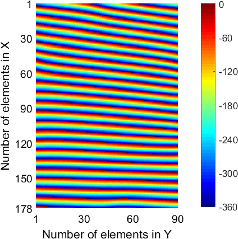
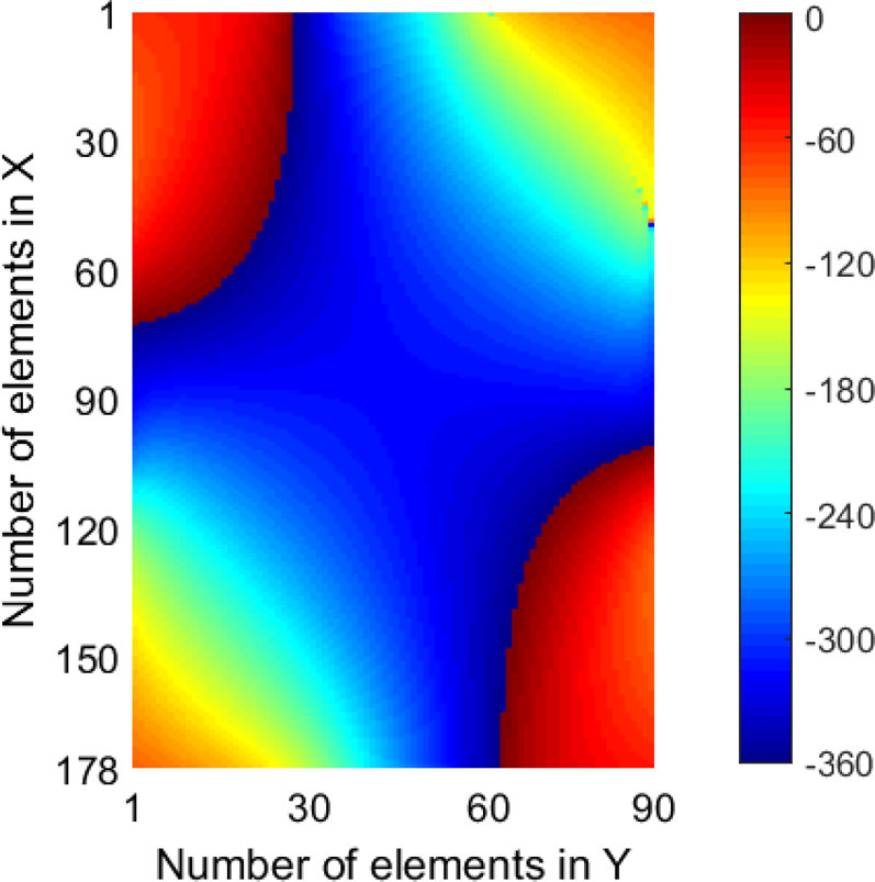
In the case under study, the two reflectarray panels are made up of 178 × 90 cells, according to the size of the KLONE panel and the reflectarray cells defined in the Section “Reflectarray cell.” Hence, the panels are formed by more than 16 000 periodic cells each panel, which means that there are more than 16 000 degrees of freedom in each polarization for the POS algorithm. In the case of K1, the synthesis is carried out running 40 iterations of the algorithm in single step and considering absolute gain masks. For K2, two steps are required, involving 20 iterations and relative gain in the first one, and 50 iterations and absolute gain requirements in the second one. When relative gain masks are used, the requirement is adjusted dynamically in each iteration in order to get the maximum achievable gain from the KLONE, but absolute gain masks are used to correct the small deviations in the coverage. The starting point and final results for the radiation patterns of each KLONE in the azimuth and elevation planes are shown in Figs 6 and 7 for K1, and in Figs 8 and 9 for K2, as well as the requirement masks. The results are shown for V-polarization, being those in H-polarization very similar. The final phase shift distributions for V-polarization obtained by POS are shown in Figs 10 and 11 for K1 and K2, respectively. In Fig. 10, the progressive phase required to tilt the beam can be clearly observed, while in Fig. 11 low phase shift range is required since the beam is reflected in the specular direction and just beam shaping is needed. A very similar result is obtained in both cases for the phase shift distributions associated to H-polarization.
Starting point for POS for K1: radiation patterns in the (a) azimuth and (b) elevation planes of a pencil beam pointing at 51° in azimuth and −18° in elevation.

Resulting pattern after POS for K1: flat-top beam in the (a) azimuth and (b) elevation planes, centered at 51° in azimuth and −18° in elevation.

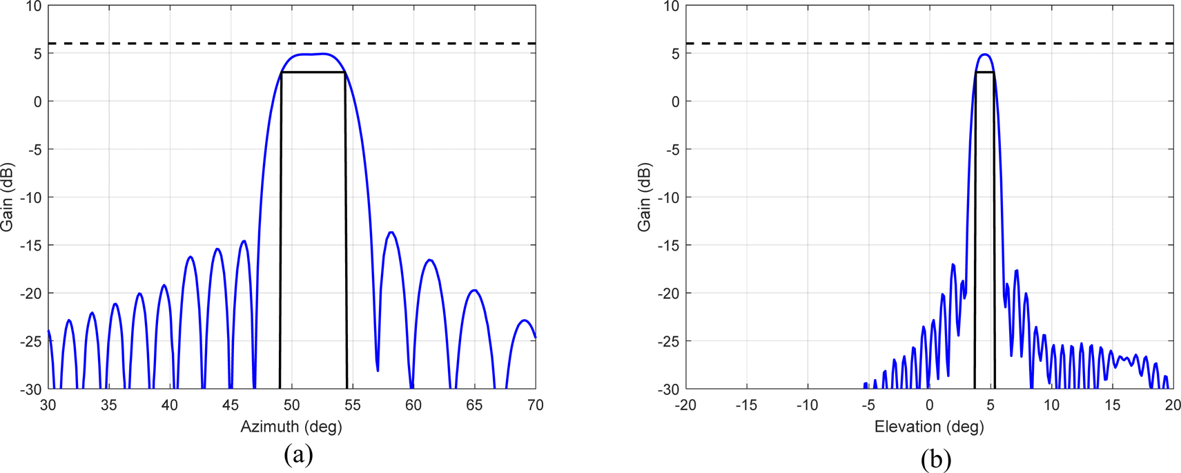
Starting point for POS for K2: radiation patterns in the (a) azimuth and (b) elevation planes of a pencil beam pointing at 52° in azimuth and −4.5° in elevation.

Resulting pattern after POS for K2: flat-top beam in the (a) azimuth and (b) elevation planes, centered at 52° in azimuth and −4.5° in elevation.
Phase distribution (in degrees) after POS for K1.
Phase distribution (in degrees) after POS for K2.
Design process and results
The printed elements on the reflectarray cells of each KLONE panel have been designed to provide the phase shift distributions computed by POS for each polarization. This process is performed by optimizing cell-by-cell the lengths of the x-oriented and y-oriented dipoles to provide the phases required in V- and H-polarizations. The lengths of the x-oriented and y-oriented dipoles can be separately adjusted thanks to the independent phase response in each linear polarization (as has been shown in Fig. 4), which simplifies the design process. Due to the large distance between the reflectarray panels and the BS, the average incidence angles from the BS have been considered for the design of each reflectarray panel (the variations in the incidence angles θi and φi are very small, as explained in the Section “Description of the outdoor scenario,” so the design can be simplified by assuming the same value of θi and φi for all the cells). After computing the dimensions of all the printed elements, the radiation patterns of the KLONE panels have been obtained by electromagnetic simulation, using the abovementioned in-house code based on the method of moments and the local periodicity approach [Reference Florencio, Boix, Carrasco, Encinar and Losada29]. The accuracy of the simulation tool to predict the radiation patterns has been experimentally validated in previous works [Reference Florencio, Encinar, Boix, Losada and Toso20, Reference Martinez-de-Rioja, Martinez-de-Rioja, Encinar, Florencio and Toso31].
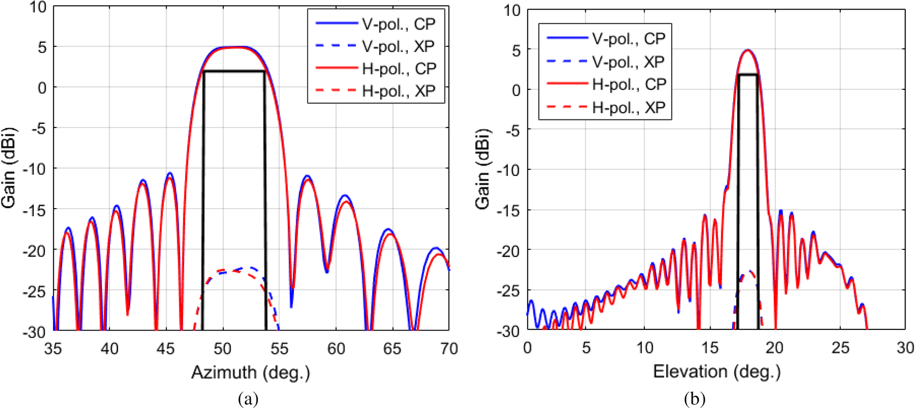
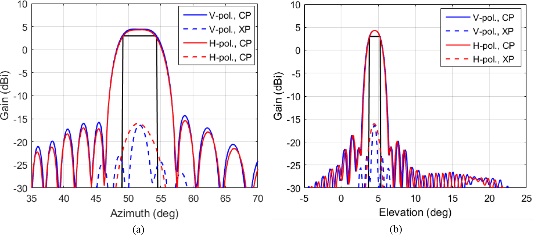
The azimuth and elevation cuts of the radiation patterns in V- and H-polarizations at 27.7 GHz (center frequency) are shown in Fig. 12 for K1 and in Fig. 13 for K1. Note that the gain of the KLONE panels has been obtained taking into account the distance and power radiated from the BS. The masks included in Figs 12 and 13 can be used to check the compliance of the radiation patterns with the scenario specifications. As can be seen, the beam pointing (51° in azimuth and 18° in elevation for K1; 52° in azimuth and −4.5° in elevation for K2) and half-power beamwidth (5.5° in azimuth and 1.5° in elevation for both K1 and K2) at the design frequency of the KLONES are both compliant with the requirements. The cross-polar components are more than 20 dB lower than the co-polar components within the region of the main lobe. Furthermore, the two KLONES present the same performance in both H- and V-polarizations.
KLONE 1: simulated radiation patterns at 27.7 GHz in the (a) azimuth and (b) elevation planes, including co-polar (CP) and cross-polar (XP) components.
KLONE 2: simulated radiation patterns at 27.7 GHz in the (a) azimuth and (b) elevation planes, including co-polar (CP) and cross-polar (XP) components.
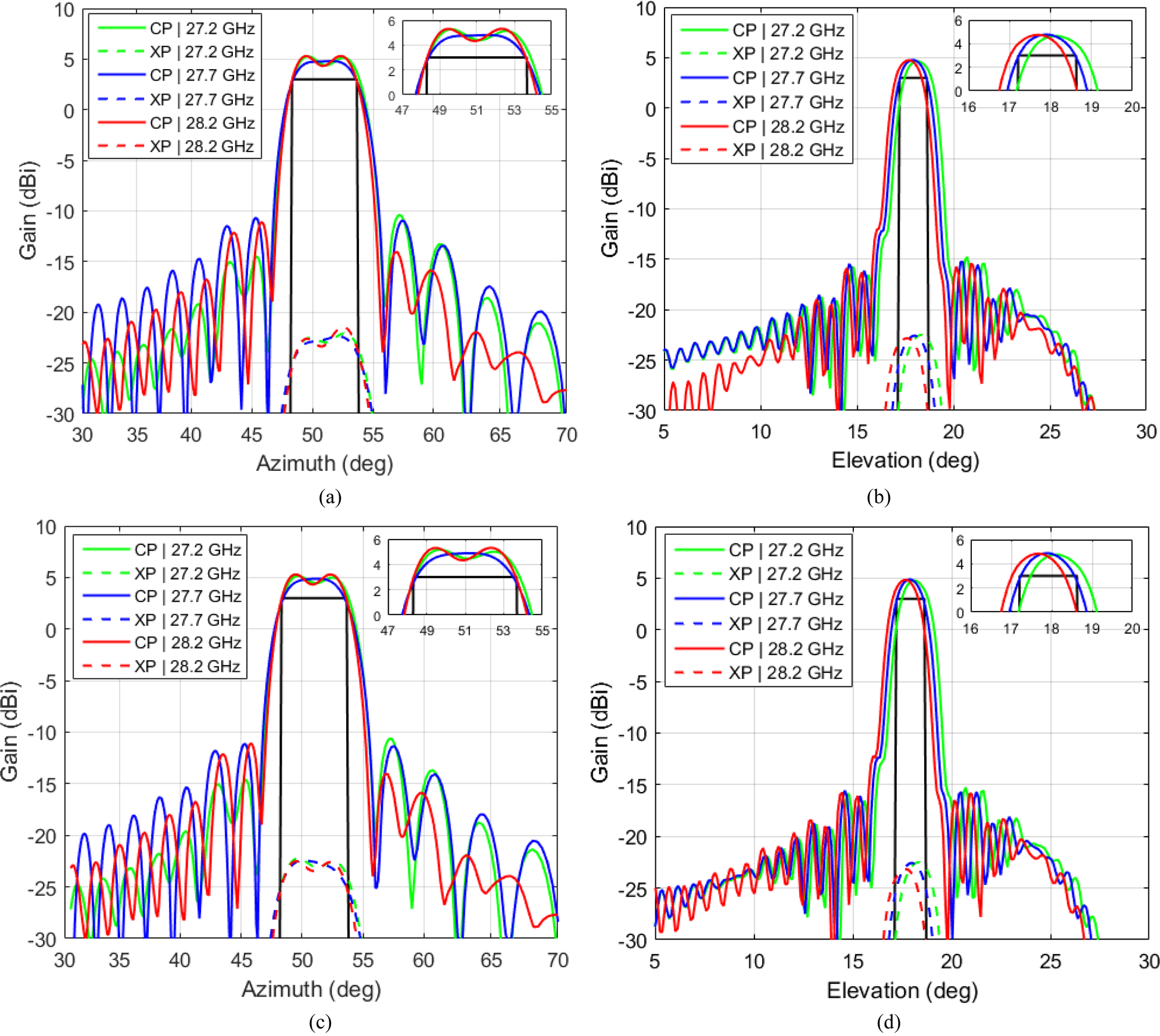
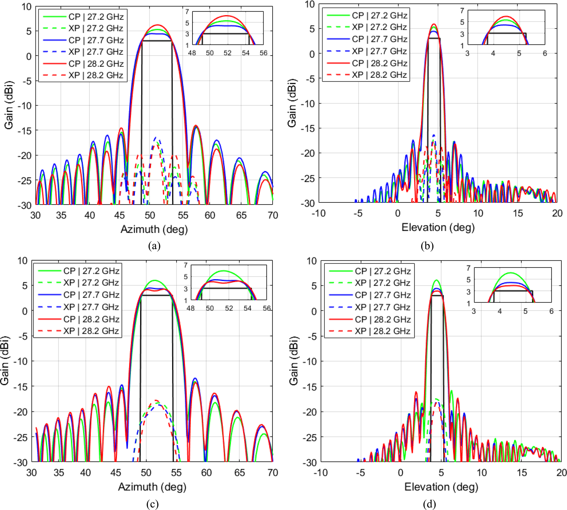
The radiation patterns of K1 and K2 in both linear polarizations have been evaluated within a 1 GHz bandwidth (27.2–28.2 GHz), in order to ensure that the KLONES can operate over two 5G channels of 400 MHz each. The radiation patterns at 27.2, 27.7, and 28.2 GHz are shown in Fig. 14 for K1 and in Fig. 15 for K2. Both KLONES show a robust performance within the operating band, with similar levels of side lobes and cross-polar components. In the case of K1, there is a slight beam squint with frequency in the elevation plane (±0.25°), which appears in the patterns of both polarizations. This beam squint can be eliminated by a more refined design process of the reflectarray panels, applying further optimizations to reduce the beam deviation with frequency.
KLONE 1: simulated co-polar (CP) and cross-polar (XP) radiation patterns at central and extreme frequencies: in V-polarization for the (a) azimuth and (b) elevation cuts, and in H-polarization for the (c) azimuth and (d) elevation cuts.
KLONE 2: simulated co-polar (CP) and cross-polar (XP) radiation patterns at central and extreme frequencies: in V-polarization for the (a) azimuth and (b) elevation cuts, and in H-polarization for the (c) azimuth and (d) elevation cuts.
Conclusions
In this paper, flat reflectarray panels are proposed to implement passive IRSs to enhance 5G mm-wave coverage in outdoor scenarios. A POS technique has been applied to obtain the phase distribution on the reflectarray that generates a broadened and deflected beam. Each reflectarray panel provides the same radiation pattern in H- and V-polarizations at the design frequency (27.7 GHz), thanks to the use of reflectarray cells based on three parallel dipoles for each linear polarization which enable independent phase adjustment in V- and H-polarizations. The reflectarray panels exhibit a stable performance within the 27.2–28.2 GHz band used for 5G communications, fulfilling the half-power beamwidth and beam pointing requirements of the scenario (the only exception is the beam pointing in the elevation plane of the first reflectarray panel, which shows a slight beam squint with frequency). These results corroborate the potential of flat reflectarray panels as a low-cost technology to implement passive IRS that will solve coverage problems in 5G mm-wave networks.
Acknowledgements
The authors would like to acknowledge Metawave Corporation for funding and leading the 5G KLONE Project. Also, the authors acknowledge the support received from the Spanish Ministry of Science and Innovation and the Spanish Research Agency within projects PID2020-114172RB-C21-2/AEI/10.13039/501100011033, from the Spanish Ministry of Economic Affairs and Digital Transformation by the NextGenerationEU under the Recovery plan for Europe and the Recovery and Resilience Facility, within the project DISRADIO TSI-063000-2021-82, and from the Vicerrectorado de Investigación of Universidad de Oviedo under Plan de Apoyo y Promoción de la Investigación under project PAPI-20-PF-15.
 Eduardo Martinez-de-Rioja received his M.Sc. and Ph.D. degrees in telecommunication engineering from the Universidad Politécnica de Madrid (UPM), Madrid, Spain, in 2014 and 2018, respectively. From 2015 to 2019, he was with the Applied Electromagnetics Group at UPM, as a research assistant. In 2016, he joined the Department of Electrical and Computer Engineering, University of Toronto, Toronto, Canada, as a visiting Ph.D. student. Since 2019, he is an assistant professor at the Department of Signal Theory and Communications and Telematic Systems and Computing, Universidad Rey Juan Carlos, Madrid, Spain. His research interests include the design of advanced antenna systems based on reflectarrays, transmitarrays, frequency selective surfaces, and other planar quasi-periodic structures for satellite communications and millimeter-wave 5G applications.
 Álvaro F. Vaquero was born in Salinas, Spain, in 1990. He received his B.Sc., M.Sc., and Ph.D. degrees in telecommunications engineering from the University of Oviedo, Gijón, Spain, in 2015, 2017, and 2021, respectively. From 2016 to 2021, he was a research assistant with the Signal Theory and Communications Area, University of Oviedo. In 2017 and 2021, he collaborated as a visiting scholar with the Antennas and Propagation Group, Instituto de Telecomunicações, Lisbon, Portugal. In December 2021, he joined the Group of Applied Electromagnetics, Universidad Politécnica de Madrid, Madrid, as a post-doc researcher. In 2022, he joined the Signal Theory and Communications Area, University of Oviedo. His current interests include the development of efficient techniques for the analysis and synthesis of reflectarray, transmitarrays, and reflective intelligent surfaces (RIS) for 5G/B5G networks, as well as near-field applications, and the design of additive manufacturing antennas in mm-wave frequencies.
 Manuel Arrebola received his M.Sc. degree from the University of Malaga, Spain, in 2002, and his Ph.D. degree from the Technical University of Madrid (UPM), Spain, in 2008. From 2003 to 2007, he was with the Electromagnetism and Circuit Theory Department, UPM, as a research assistant. In 2007, he joined the Electrical Engineering Department, Universidad de Oviedo, Gijón, Spain, where he is currently an associate professor. In 2009, he enjoyed a research stay at the ESTEC, European Space Agency, Noordwijk, The Netherlands. In 2018, he was with the Edward S. Rogers Sr. Department of Electrical and Computer Engineering, University of Toronto, Toronto, Canada, and in 2019 with the Institute of Sensors, Signals and Systems, Heriot-Watt University, Edinburgh, UK, both as visiting professor. His current research interests include the development of efficient techniques and technologies for spatially fed antenna design with application in near and far fields.
 Eduardo Carrasco is an associate professor at Universidad Politécnica de Madrid (UPM). He completed his bachelor's degree in telecommunication engineering at the National Autonomous University of Mexico (UNAM) in 2000, and his Ph.D. degree in telecommunication engineering at UPM in 2008. From 2009 to 2012, he was with the Electromagnetism and Circuits Theory Department at UPM, as a postdoctoral researcher. From 2012 to 2014, he was at the Swiss Federal Institute of Technology in Lausanne (EPFL), as a Marie-Curie Fellow. Dr. Carrasco was with the Foundation for Research on Information Technologies in Society (IT'IS), Zurich, from 2015 to 2017. He has participated in different projects supported by the Spanish Government, the Mexican Council of Science and Technology, the Swiss Government, the European Union's Sixth and Seventh Framework Programs, the European Space Agency (ESA), and the industry. He is a Senior Member of the Institute of Electrical and Electronics Engineers (IEEE).
 Jose A. Encinar is professor at Universidad Politécnica de Madrid (UPM) since 1991. He received his Master's and Ph.D. degrees in electrical engineering from UPM in 1979 and 1985, respectively. He is the leader of the Research Group GEA (https://gea.ssr.upm.es) at UPM. He has a vast experience in developing software tools, designing, manufacturing and testing dichroic subreflectors, printed array and reflectarray antennas for space and terrestrial communications. Prof. Encinar has co-authored more than 100 journal and 200 conference papers, one book, and several book chapters, and he is the co-inventor of 10 patents. He received the “2005 H.A. Wheeler Applications Prize Paper Award” and the “2007 S.A. Schelkunoff Transactions Prize Paper Award” by IEEE Antennas and Propagation Society, and the “EuRAAP Antenna Award 2022” by the European Association on Antennas and Propagation (EurAAP). He has been TPC chair of the 16th European Conference on Antennas and Propagation (EuCAP2022).
 Maha Achour has more than 25 years' experience in leadership roles in the semiconductor, wireless RF, optical communications, sensing and defense industries – with both startup and public companies. Recognized for her deep technology background, management, and business development skills, Maha has been recently named to Forbes' “50 Over 50 – Vision” list of women who are successfully running companies and leading movements. Before founding Metawave, she served as co-founder and CEO of Polyceed-Dyenamics (where she serves now as Chair of the Board), co-founder and CTO of Rayspan, Director of Advanced Technology at SDRC (Boeing), Director of Advanced Technology at Optical Access, and lead System Engineer at Tiernan Comm where she worked on first broadcast HDTV-over satellite system. She has also led various DARPA projects in advanced wireless MIMO and optical device technologies. A sought-after industry speaker and thought leader, Maha holds a doctorate degree in physics from the Massachusetts Institute of Technology (MIT). She has authored more than 35 publications, holds more than 75 granted patents, and has more than 150 pending patent applications.


 Open access