

Introduction
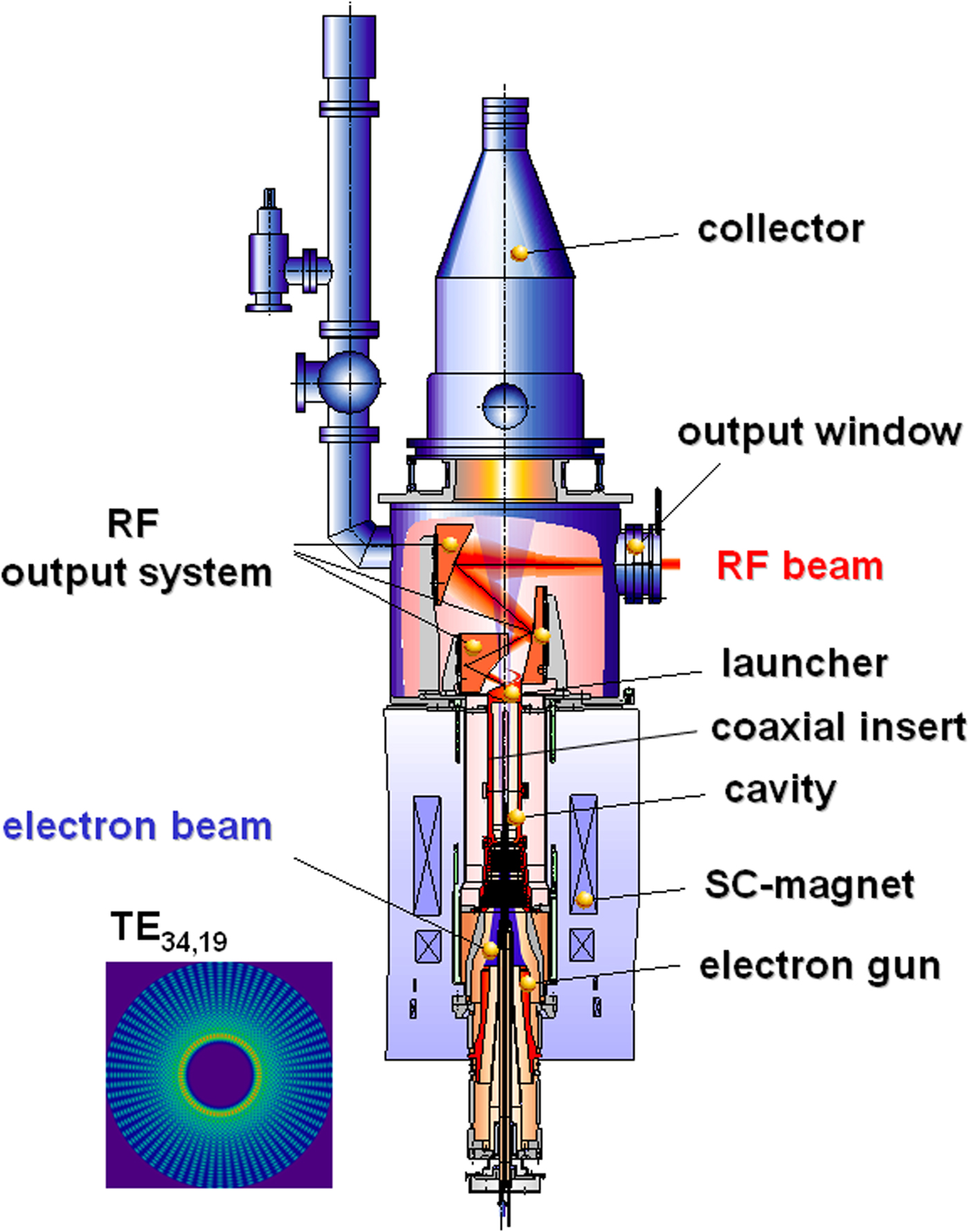
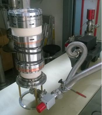
At Karlsruhe Institute of Technology (KIT), the activities in gyrotron research and development shall lead to a gyrotron design that will fulfil the increasing requirements for a possible upgrade for the International Thermonuclear Experimental Reactor (ITER) [Reference Omori, Henderson, Albajar, Alberti, Baruah, Bigelow, Beckett, Bertizzolo, Bonicelli, Bruschi, Caughman, Chavan, Cirant, Collazos, Cox, Darbos, de Baar, Denisov, Farina, Gandini, Gassmann, Goodman, Heidinger, Hogge, Illy, Jean, Jin, Kajiwara, Kasparek, Kasugai, Kern, Kobayashi, Kumric, Landis, Moro, Nazare, Oda, Pagonakis, Piosczyk, Platania, Plaum, Poli, Porte, Purohit, Ramponi, Rao, Rasmussen, Ronden, Rzesnicki, Saibene, Sakamoto, Sanchez, Scherer, Shapiro, Sozzi, Spaeh, Strauss, Sauter, Takahashi, Temkin, Thumm, Tran, Udintsev and Zohm1] as well as the minimum requirements for a future DEMOnstration power plant (DEMO) [Reference Federici, Giruzzi, Lowry, Kemp, Ward, Wenninger, Zohm, Bachmann, Morlock, Harman, Meszaros, Franke, Gonzalez, Gadomska and Hurzlmeier2], the nuclear fusion demonstration power plant that will follow ITER. Today, the requirements for the initial gyrotron installation at ITER are a radio frequency (RF) output power capability of 1 MW (3600 s) at an operating frequency of 170 GHz for each single gyrotron [Reference Jelonnek, Gantenbein, Hesch, Jin, Pagonakis, Piosczyk, Rzesnicki, Thumm, Alberti, Hogge, Tran, Erckmann, Laqua, Michel, Benin, Legrand, Rozier, Avramidis, Vomvoridis, Ioannidis, Latsas, Tigelis, Albajar, Bonicelli and Cismondi3]. The expected performance requirement for a possible ITER upgrade is an RF output power of significantly larger than 1 MW. For future DEMO an RF output power level of minimum 2 MW CW at even higher operating frequencies up to 240 GHz is under consideration [Reference Franck4, Reference Jelonnek, Aiello, Alberti, Avramidis, Braunmueller, Bruschi, Chelis, Franck, Franke, Gantenbein, Garavaglia, Granucci, Grossetti, Illy, Ioannidis, Jin, Kalaria, Latsas, Pagonakis, Rzesnicki, Ruess, Scherer, Schmid, Strauss, Wu, Tigelis, Thumm and Tran5]. It is expected that the coaxial-cavity gyrotron [Reference Dumbrajs and Nusinovich6, Reference Flyagin, Khizhnyak, Kuftin, Manuilov, Pavelyev, Pavelyev and Zapevalov7] technology will allow an operation at those output power levels. Compared with the conventional hollow-cavity gyrotron technology as used for, e.g. Wendelstein7-X (W7-X) and ITER today, the coaxial-cavity gyrotron technology allows the effective reduction of the voltage depression due to the space charge effect of the electron beam and the reduction of the mode competition due to the mode selectivity of the carefully chosen corrugated inner conductor at high operating frequencies. First experimental results obtained with the 170 GHz 2 MW short-pulse coaxial-cavity pre-prototype (Fig. 1) at pulse length of a few milliseconds (ms) have shown the potential of the coaxial-cavity concept in the multi-MW operation regime. Nonetheless, until today, the coaxial-cavity gyrotron technology has not been verified at longer pulses above a few ms. Therefore, a focus of KIT is the verification of this technology at pulse lengths up to 1 s which will prove the long-pulse capabilities for longer pulses also. For the very first time, a coaxial cavity gyrotron will be operated and investigated in the experiment in long-pulse operation.
Sketch of the 2 MW 170 GHz KIT coaxial-cavity gyrotron.
In particular, the paper is organized as following. In the Review of experimental results of the modular short-pulse prototype section, the experimental results of the modular pre-prototype coaxial-cavity gyrotron are presented. Then, in the Design and manufacturing of the coaxial-cavity longer-pulse pre-prototype gyrotron section the coaxial-cavity gyrotron design and manufacturing process of the launcher, cavity, beam tunnel, and mirror box as well as the vacuum compatible connections are presented. In addition to [Reference Ruess, Avramidis, Fuchs, Gantenbein, Illy, Kalaria, Kobarg, Pagonakis, Rzesnicki, Thumm, Weggen and Jelonnek8], the present extended paper presents in the Advanced magnetron injection guns subsection two advanced and innovative magnetron injection guns (MIG), which are designed for stable long-pulse operation.
Review of experimental results of the modular short-pulse prototype
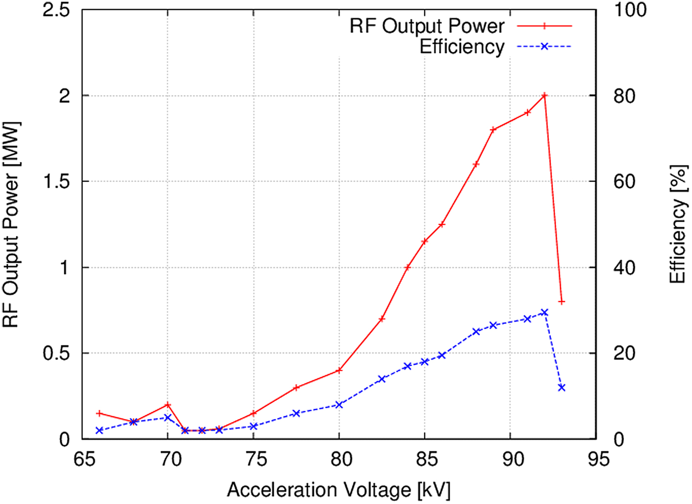
During the experimental short-pulse test campaign, the already existing KIT 170 GHz 2 MW coaxial-cavity modular pre-prototype did show an excellent and very stable performance. The tube was operated at an acceleration voltage of up to U c = 93 kV and an electron beam current of I b = 80 A. At the nominal operating parameters, listed in Table 1 (U c = 90 kV, I b = 75 A), an RF output power of 2 MW up to 10 ms pulse length has been achieved. An electronic (interaction) efficiency between the electron beam and the electromagnetic field of ~30% was achieved at nominal operating parameters [Reference Rzesnicki, Piosczyk, Kern, Illy, Jin, Samartsev, Schlaich and Thumm9]. During the experiments, the magnetic field of the superconducting magnet was set to 6.90 T. The acceleration voltage was shifted up to ~93 kV. At the same time, the electron beam current was set to 80 A. That allowed to generate a world record in RF output power of 2.2 MW at 170 GHz. The calorimetrically measured RF output power and electronic efficiency versus cathode voltage is shown in Fig. 2 [Reference Rzesnicki, Piosczyk, Kern, Illy, Jin, Samartsev, Schlaich and Thumm9]. The achieved results are in excellent agreement with the multi-mode simulations done at KIT [Reference Rzesnicki, Piosczyk, Kern, Illy, Jin, Samartsev, Schlaich and Thumm9].
Measured RF output power and overall efficiency as a function of the accelerating voltage U c (obtained at B cav = 6.87 T and I b ~75 A, operation without depressed collector).
Design parameters for the coaxial-cavity gyrotron
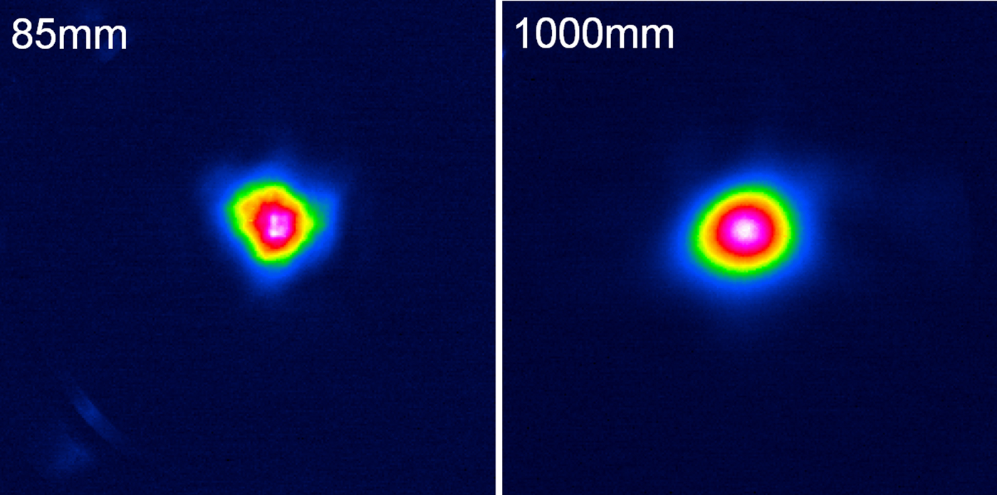
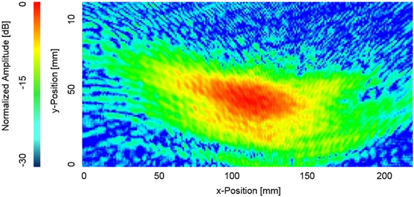
The experimental results were performed with an improved design of the launcher [Reference Jin, Thumm, Piosczyk, Kern, Flamm and Rzesnicki10] with smoothed inner wall corrugations. That launcher is the major part of the quasi-optical system which converts the very high-order mode into a Gaussian mode. The efficiency of the mode converter had been verified in low-power measurements before implementing that launcher into the pre-prototype. The measured results are in excellent agreement with the expectations from numerical analysis. The fundamental Gaussian mode content had been extracted from the measured patterns and was calculated to be around 96%. In addition, at high output power, the profile of the RF beam had been measured with an infrared camera (IR-camera) (Fig. 3 [Reference Rzesnicki, Piosczyk, Kern, Illy, Jin, Samartsev, Schlaich and Thumm9]) at several different distances from the microwave window. The analysis of the data verified again the very good quality of the generated RF beam and it is in accordance with the low-power measurements. The amount of the RF stray radiation losses inside the gyrotron tube had been obtained by measuring the RF power radiated through the relief window with a very sensitive ballistic calorimeter. Finally the stray radiation losses with the new launcher are significantly reduced from 7% (previous experiments) down to 4% [Reference Rzesnicki, Piosczyk, Kern, Illy, Jin, Samartsev, Schlaich and Thumm9].
IR image of the measured gyrotron RF output beam in 85 and 1000 mm distance from the window.
Design and manufacturing of the coaxial-cavity longer pulse pre-prototype gyrotron
In order to increase the pulse length from the ms-range up to range of 1 s, the main components of the 2 MW coaxial-cavity gyrotron such as the beam tunnel, the cavity, the launcher, the mirrors, the chemical vapor deposited (CVD) diamond RF output window, and the collector have to be equipped with an active cooling system. The corresponding design activity was starting in 2015 already. The final design of the longer pulse gyrotron with the already manufactured components is shown in Fig. 4. One of the main project requirements is to keep the modularity of the gyrotron. Therefore, an independent cooling system for each component is considered. This allows the monitoring of the internal losses in each gyrotron component and of the final energy balance of the tube during longer pulse operation. In the following, the advanced, water-cooled components are presented. The longer pulse components as well as the inverse magnetron injection gun (IMIG) are manufactured, brazed, and assembled at the KIT for the very first time.
Subcomponents of the KIT 170 GHz 2 MW coaxial-cavity longer pulse gyrotron.
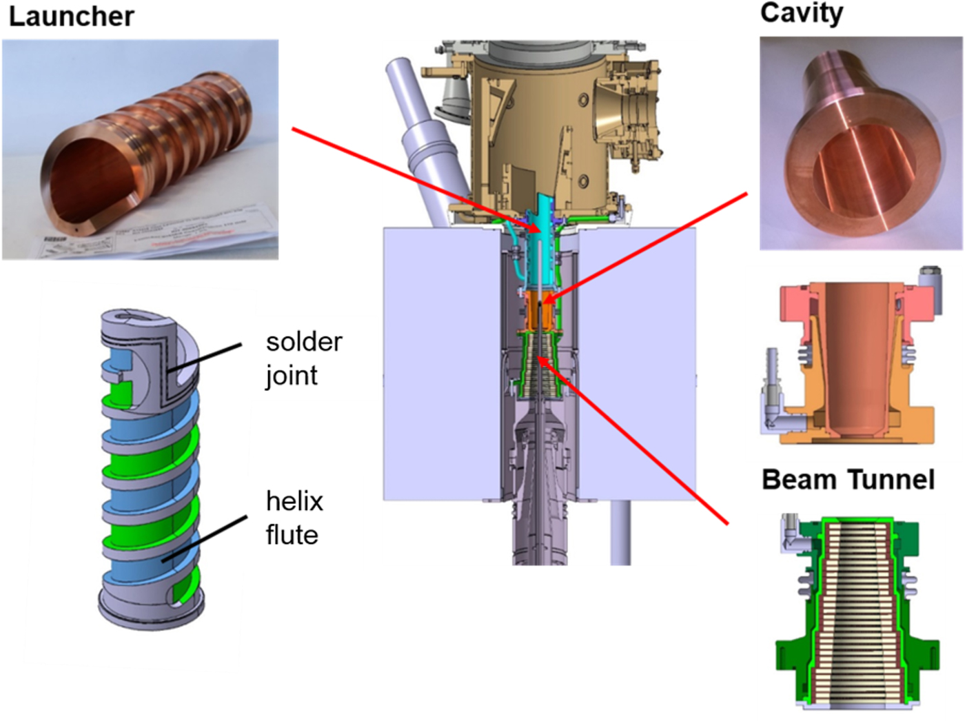
Launcher
As stated before already, the launcher together with the mirror system is responsible for the conversion of the main TE34,19-mode into the fundamental Gaussian mode of the RF output beam [Reference Jin, Thumm, Piosczyk, Kern, Flamm and Rzesnicki10]. Especially, at the tip of the launcher, where the complete RF-power is finally focused, the thermal loading of 0.4 kW/cm2 is critical. In order to achieve a stable operation, it is necessary to cool that launcher tip therefore. To achieve that, the water inlet and outlet of the launcher is connected at the bottom of the launcher. A helix cooling structure was proposed to make that configuration possible. Due to that helix structure (see. Fig. 4), the channels have to be milled with a five-axis milling cutter. In order to caulk the channels, a stainless steel coat is imposed and brazed from the outside of the launcher. The introduction of a bellow is necessary as the launcher and the coat consist of different materials that have different thermal expansion coefficients. The already manufactured launcher shows an excellent surface quality. The tolerances are in the range of below ±10 µm. The launcher performance has been successfully verified in the cold measurement test setup. Figure 5 shows the radiated pattern which was sampled at a distance of 10 cm from the axis to the position of the first mirror. The measurement results correspond well to the simulation results and the measurements of the previous launchers. The simulated radiation pattern is being calculated with the full wave three-dimensional (3D) vector analysis code SURF 3D [Reference Neilson11]. Furthermore, excellent soldered and brazed joints with a leakage rate of <10−12 mbar l/s were achieved for the launcher parts.
Radiation pattern of the water-cooled launcher.
Cavity
At the gyrotron cavity, the kinetic energies of the individual electrons of the electron beam are transferred to the electromagnetic field. The expected total power loss in the cavity due to thermal wall loading is about 50 kW at nominal 2 MW gyrotron operation. Due to the high quality factor of the cavity, one finds the peak thermal wall loading of approximately 2 kW/cm2 in a very narrow region at the center of the cavity. It leads to a very high-temperature gradient at the inner side of the cavity wall, which results in thermal stress, and finally, leads to a deformation of the cavity wall. Depending on that deformation, the operating frequency of the gyrotron is shifted and the quality factor of the cavity is changing significantly. Therefore, it is mandatory to implement an effective water cooling. The chosen approach of the active cooling system is similar to the design of the cooling system for the launcher. However, due to the position and orientation, the implementation of a helix-type channel system is not necessary. The different temperatures and material properties of the coat and the outer cavity wall require also the implementation of a bellow. The reduction of the water cooling gap (see Fig. 4, cavity) increases the flow velocity of the water and therefore the cooling capacity. The limitation of the cavity is a maximum temperature of approximately 350 °C. Based on the temperature limitations, the multi-physics software COMSOL predicts a maximum pulse length of approximately 1 s.
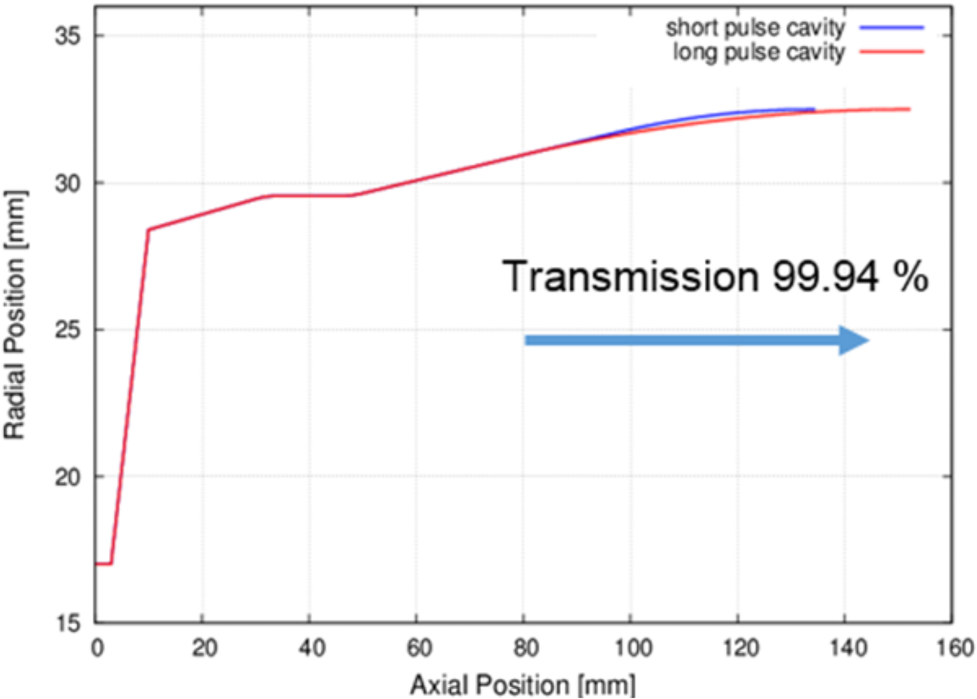
Additionally, the cavity uptaper is extended and optimized (Fig. 6). The simulation results predict a transmission of 99.94% of the TE34,19-mode and a very low mode conversion.
Optimized cavity design of the longer pulse gyrotron configuration compared with that of the existing short-pulse configuration.
Beam tunnel
The beam tunnel consists of stacked copper and ceramic rings. Compared with the cavity, the thermal loading is relatively low. However, an active cooling is considered also. Figure 4 shows the construction of the beam tunnel including the water cooling system. A coat is brazed to the outside of the beam tunnel. Together with the outer metal layer, it forms an annular gap for the cooling water.
Mirror box
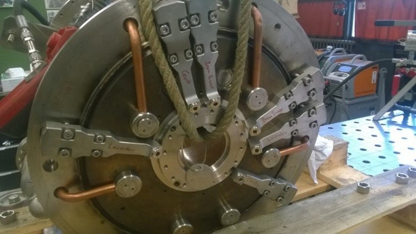
In order to build-up a cost-effective pre-prototype gyrotron, the mirrors and the mirror box of the quasi-optical system are reused from the refurbished industrial coaxial-cavity gyrotron prototype [Reference Hogge, Goodman, Alberti, Albajar, Avramides, Benin, Bethuys, Bin, Bonicelli, Bruschi, Cirant, Droz, Dumbrajs, Fasel, Gandini, Gantenbein, Illy, Jawla, Jin, Kern, Lavanchy, LiÉvin, MarlÉtaz, Marmillod, Perez, Piosczyk, Pagonakis, Porte, Rzesnickl, Siravo, Thumm and Tran12, Reference Kern, Gantenbein, Illy, Jelonnek, Jin, Pagonakis, Piosczyk, Rzesnicki and Thumm13]. Nevertheless, slight modifications of the absorber ceramics, collector flanges, and window housing are necessary in order to satisfy the requirement of the modularity. The redesigned mirror box is shown in Fig. 4 and Fig. 7. The water inlets for the mirrors, the beam tunnel, the cavity, and the launcher are fixed at the bottom of the mirror box (Fig. 7). Due to the fact that the gyrotron will operate at pulse lengths of up to 1 s, it is necessary to bake out the tube at 350 °C. This requires that the water channels and connections are heat-resistant up to the maximum bake-out temperature. Therefore, metallic sealed components are added to the construction. Already, a first prototype of a metallic sealed water connection was developed, which has shown excellent performance at the nominal operating water pressure.
Bottom view of the mirror box with the water connections for each subcomponent.
Vacuum compatible connections
One of the most critical issues in a gyrotron is the high-vacuum compatible brazed and welded joints. Figure 8 shows the grinding patterns of different brazed and soldered joints with variable material compositions. At the top of Fig. 8, two grinding patterns of a soldered joint with Glidcop [14] and stainless steel are shown. It shows that that the solder diffused into the gap between Glidcop and stainless steel perfectly due to the capillary forces caused by the carefully designed and manufactured gap between both materials. In addition, excellent solder joints between CVD diamond and copper were achieved.
Examples for grinding patterns of brazed and welded joints.

At the bottom of Fig. 8, the grinding patterns of an electron beam welded joint with iron-nickel and stainless steel as well as CuCrZr (copper chrome zirconium) with iron-nickel is shown. At the welded joint, both materials coalesced perfectly with excellent leak tightness. In both scenarios, the leakage rate is below 10−12 mbar l/s.
Advanced MIG
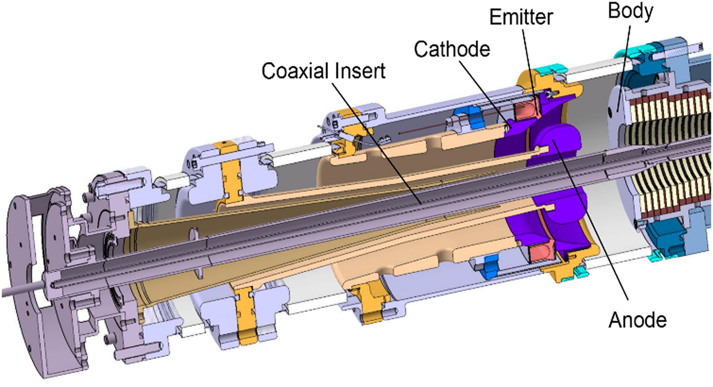
A major step toward higher output power and operating frequency is the IMIG [Reference Ruess, Pagonakis, Gantenbein, Illy, Rzesnicki, Thumm and Jelonnek15]. An IMIG has been designed and already manufactured for the KIT 2 MW coaxial-cavity gyrotron [Reference Rzesnicki, Gantenbein, Illy, Jelonnek, Jin, Pagonakis, Piosczyk, Schlaich and Thumm16]. It is expected that this gun leads to a more stable operation at even higher output power. Due to the triode configuration of the MIG, including a separate modulation anode, the IMIG has the flexibility to be operated at multiple frequencies such as 170 and 204 GHz. Because of the possibility of larger emitter radius, the gyrotron can be operated at a larger operating beam current and therefore at a higher RF output power. The requested beam and operating parameters are presented in Table 1 and Table 2. The simulated parameters of the IMIG indicate a high electron beam quality [Reference Ruess, Pagonakis, Gantenbein, Illy, Rzesnicki, Thumm and Jelonnek15], which promises a reliable gyrotron operation at nominal operating parameters. Additionally, the IMIG is the first MIG which fulfils the design criteria for preventing the generation of trapped electrons as presented in [Reference Pagonakis, Piosczyk, Zhang, Illy, Hogge, Avramidis, Rzesnicki and Jelonnek17]. The generation of a beam halo is suppressed by the use of two halo shields [Reference Ruess, Pagonakis, Gantenbein, Illy, Rzesnicki, Thumm and Jelonnek15]. Based on its triode configuration, the presented IMIG can be modified and operated in a conventional hollow gyrotrons easily [Reference Ruess, Avramidis, Gantenbein, Illy, Pagonakis, Rzesnicki, Thumm and Jelonnek18]. In the existing IMIG design, the emitter radius is set to 62 mm with an emitter thickness of 5 mm. The emitter has an angle of 25° with respect to the z-axis of the tube. In order to keep the temperature in the neighboring regions of the emitter low at both edges, isolation gaps with a width of 200 µm are designed. As a result, the electrons, emitted from the emitter edges have a very high pitch factor, which is related to the field enhancement at the emitter edges. In order to eliminate the electrons with high pitch factor, the emitter is pushed into the cathode by 70 µm in order to reduce the local electric field.
Electron beam parameters at the cavity center
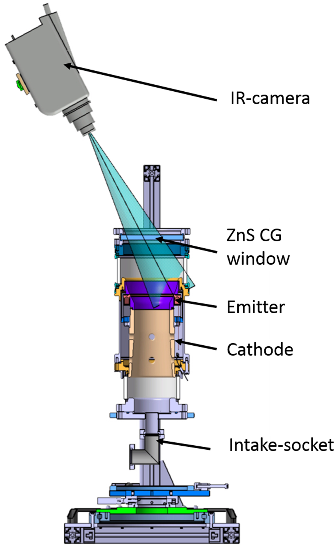
The alignment of the components of a MIG against the z-axis of the gyrotron and the individual subcomponents of that MIG against each other is one of the most critical issues during manufacturing and final assembly of any gyrotron. A misalignment of any subcomponent reduces the quality of the electron beam significantly. Even a misalignment in the range of a few hundreds of micrometers can significantly impact the beam parameters. Hence, the tolerance margin for the positioning of the emitter in the tube is the key for the creation of a properly performing tube. Additional to the above described manufacturing and assembly tolerances, the different thermal expansions of the different components during operation are impacting the quality of the tube. In order to minimize that thermal effect, the thermo-mechanical behavior was investigated by the use of COMSOL. In comparison to the “conventional” MIG (Fig. 13), the cathode and emitter of the IMIG (Fig. 9) are placed at the outside of the MIG. Hence, it is directly cooled by passing oil at the outer surface of the cathode elements. That is the major benefit if comparing to the standard MIG used in all conventional gyrotrons. The components of the cathode and anode are made of materials with high thermal conductivity, mainly CuCrZr (indicated in Fig. 9 using orange color) and molybdenum (Fig. 9, marked by dark blue color). Therefore, the heat loading of the neighboring emitter regions is directly guided outside of the MIG and absorbed by the oil flow. Compared with conventional MIGs, the temperature of the loaded parts is significantly reduced by 40% down to ~150 °C. Corresponding simulation results are presented in [Reference Ruess, Zeng, Gantenbein, Illy, Pagonakis, Rzesnicki, Thumm and Jelonnek19]. In order to verify the simulations, a measurement setup was designed and manufactured (see Fig. 10).
Sketch of the already manufactured inverse magnetron injection gun.
Measurement setup for the verification of the emitter temperature distribution.
Assembled inverse magnetron injection gun during bake-out process.

Another significant influence on the beam quality, hence on the generated output power and efficiency, is caused by an inhomogeneous temperature distribution at the surface of the emitter. Obviously an inhomogeneous temperature distribution leads to an inhomogeneous emission. The emission inhomogeneity can be experimentally investigated by measuring the current–voltage characteristics as published in [Reference Zhang, Illy, Pagonakis, Malygin, Samartsev, Rzesnicki, Gantenbein, Dammertz, Piosczyk, Thumm and Jelonnek20].
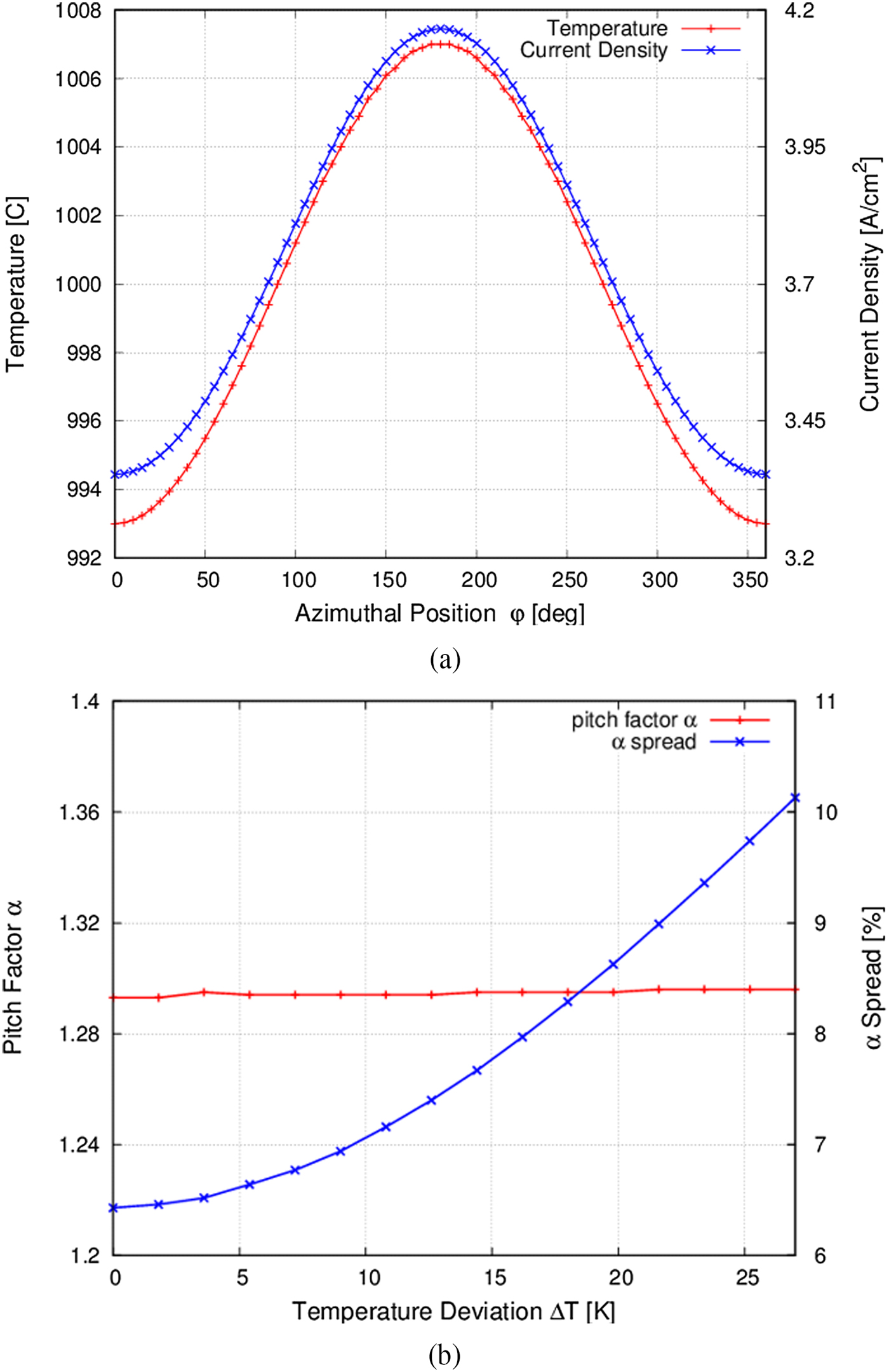
Measurements of the temperature distribution of the emitter of the IMIG did indicate an azimuthal sinusoidal temperature distribution (see Fig. 12(a)). The expected nominal temperature was 1000 °C, whereas the measured minimum temperature was 993 °C, measured at the connections of the heater. The reason for this lower temperature is that the ends of the filament are not overlapping each other. Using the Child–Langmuir Law, the calculated current density is 3.4 A/cm2 at minimum temperature and 4.16 A/cm2 at the maximum temperature considering a temperature difference of ΔT = +7 °C. Considering that measured temperature inhomogeneity, the simulated pitch factor spread is slightly increased from 6.5 up to 6.7% as shown in Fig. 12(b). With increasing temperature inhomogeneity, the spread increases up to 10% at a temperature distribution of ±27 °C, while the average pitch factor remains constant [Reference Ruess, Gantenbein, Illy, Kobarg, Pagonakis, Rzesnicki, Thumm, Weggen and Jelonnek21].
(a) Temperature distribution (blue) and current density (red) as a function of the azimuthal emitter position, (b) pitch factor and RMS α spread simulated at the cavity.
Overall, the measurements of the surface quality and the mechanics tolerances of the manufactured IMIG (see Fig. 11) shows an excellent surface condition and only small tolerances in the final assembly which promise a homogenous electric field distribution in the emitter region and a high quality of the hollow electron beam. The emitter position will be checked by the help of a precise optical laser measurement. Furthermore, excellent welding and solder joints with a very low leakage rate of <10−12 mbar l/s has been achieved.
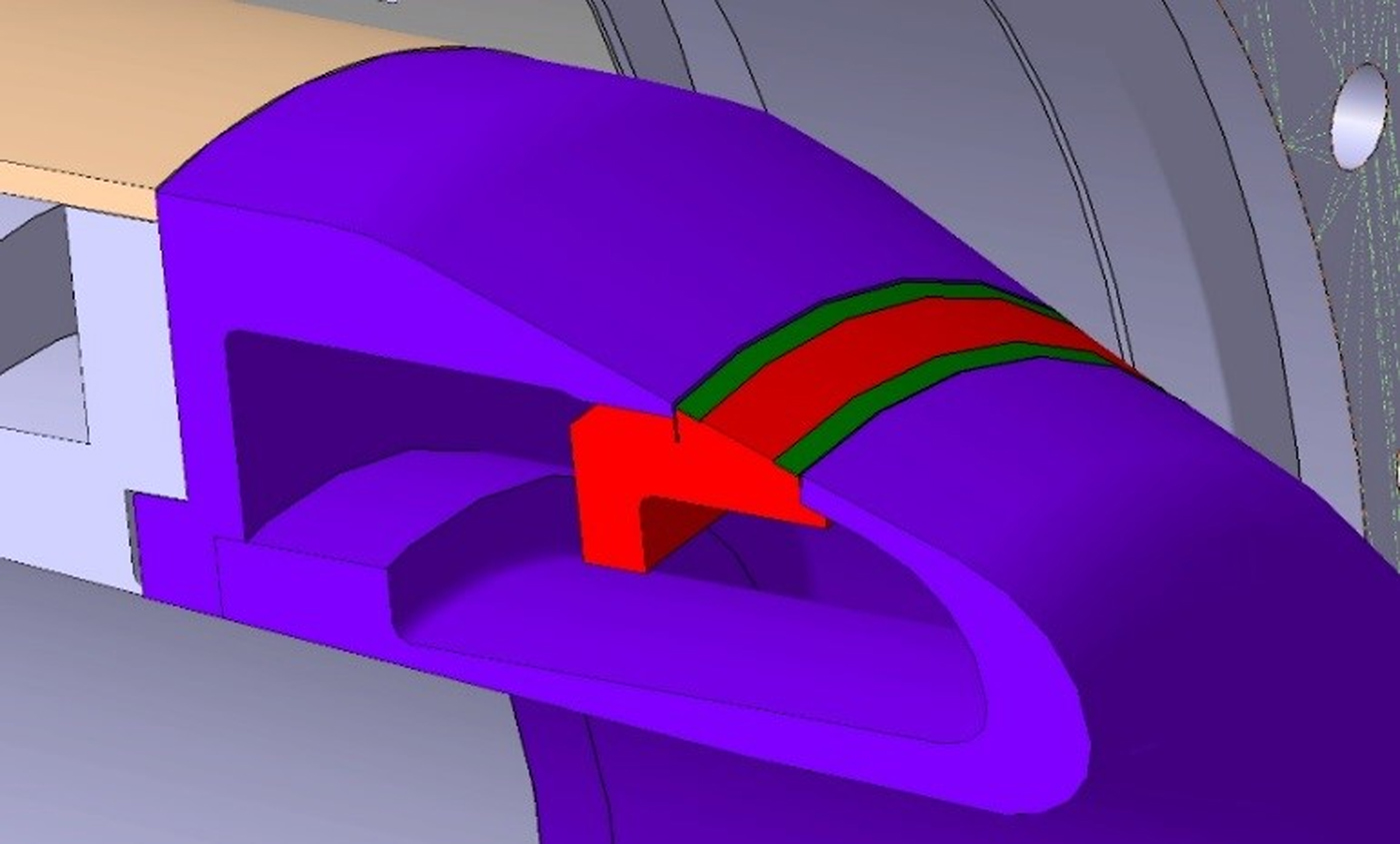
It was already mentioned that the field enhancement at the emitter edges has a significant influence regarding the electron beam quality. Tolerance studies of the radial emitter position have confirmed those observations and have shown that the manufacturing tolerances of some microns becomes critical. A possible solution for this major issue is the implementation of an anti-emission coating at the edges of the emitter. For example, considering a misalignment of ±80 µm, the variation of the pitch factor measured over the emitter area is 83.3% smaller compared with the variation using a conventional emitter [Reference Pagonakis, Illy and Thumm22]. A new conventional MIG with an advanced coated emitter for the 170 GHz 2 MW longer pulse coaxial-cavity gyrotron, as shown in Fig. 13, is already in final manufacturing.
Advanced conventional magnetron injection gun with an anti-emission coating (colored in green) at the emitter (colored in red).
Conclusion
KIT is pushing forward the coaxial-cavity gyrotron development by building up a modular longer pulse 170 GHz, 2 MW pre-prototype targeting at a pulse length of up to 1 s. The design principle and the manufacturing process of that pre-prototype have been presented here. All the subcomponents have been manufactured, brazed, and successfully tested regarding vacuum tightness. Furthermore, the IMIG is manufactured at KIT with an expected high electron beam quality. Additionally, an advanced conventional MIG with coated emitter is still under production at Thales Electron Devices. Both MIGs can be operated in hollow as well as in a 204 GHz coaxial-cavity gyrotron. The longer pulse 2 MW coaxial-cavity gyrotron and the IMIG will be tested before the end of 2017.
Acknowledgement
This work has been carried out within the framework of the EUROfusion Consortium and has received funding from the Euratom research and training programme 2014–2018 under grant agreement No 633053. The views and opinions expressed herein do not necessarily reflect those of the European Commission.
 Sebastian Ruess received the B.S. degree in electrical engineering from the University of Ulm, Ulm, Germany, in 2011 and the M.S. degree in electrical engineering and information technology with a focus on microwave technology from the Karlsruhe Institute of Technology (KIT), Karlsruhe, Germany, in 2014. He is currently with the Institute for Pulsed Power and Microwave Technology, KIT, where he is involved in development of fusion gyrotrons.
 Konstantinos A. Avramidis was born in Athens, Greece, in 1971. He received the Dipl.Ing. and Ph.D. degrees from the School of Electrical and Computer Engineering, National Technical University of Athens, Athens, in 1998 and 2006, respectively. He joined the Institute for Pulsed Power and Microwave Technology, Karlsruhe Institute for Technology, Karlsruhe, Germany, in 2013. Dr. Avramidis is a member of the Technical Chamber of Greece.
 Maximilian Fuchs acquired his B.Eng. degree in mechanical engineering with a focus on construction from the Baden-Wuerttemberg Cooperative State University, Karlsruhe, Germany, in 2016. From September 2016 to September 2017 he worked as a mechanical engineer at the Institute for Pulsed Power and Microwave Technology, KIT, where he was responsible for the construction of fusion gyrotrons. Currently he works on his M.Eng. degree in mechanical engineering at the University of Applied Sciences, Kaiserslautern, Germany.
 Gerd Gantenbein received the Dipl.-Phys. Degree in physics and the Dr.-Ing. degree in electrical engineering from the University of Karlsruhe, Karlsruhe, Germany, in 1988 and 1993, respectively. He has been with the Institute for Pulsed Power and Microwave Technology, KIT, where he is currently the Head of the Division High Power Microwave Technology.
 Zisis C. Ioannidis received the B.S. degree in physics, the M.S. degree in electronics, and the Ph.D. degree from the National and Kapodistrian University of Athens, Athens, Greece, in 2002, 2004, and 2008, respectively. Since 2016, he has been with the Institute for Pulsed Power and Microwave Technology, Karlsruhe Institute of Technology, Karlsruhe, Germany.
 Stefan Illy received the Dipl.-Phys. and Dr.rer.nat. degrees in physics from the University of Karlsruhe, Karlsruhe, Germany, in 1993 and 1997, respectively. He has been with the High Power Microwave Technology Division, Institute for Pulsed Power and Microwave Technology, KIT since 1999, where he currently leads the Gyrotron Interaction Analysis and Components Group.
 Jianbo Jin was born in Guizhou Province, China, in April 1968. He received the M.Sci. and Ph.D degrees in Southwest Jiaotong University, Chengdu, China, in 1993 and 2006, respectively. Since 2002, his researches have been concentrated on high power gyrotorns at the Karlsruhe Institute of Technology, KIT (former Research Center Karlsruhe, FZK), Germany. His interests include high-power microwave generators, electromagnetic wave transmission, mode conversion, and numerical simulations in electromagnetic engineering.
 Parth C. Kalaria was born in Rajkot, India, in 1988. He received the B.Tech. degree in electronics and communication engineering from the Institute of Technology, Nirma University, Ahmedabad, India, and the M.Tech. degree in RF and microwave engineering from Indian Institute of Technology Roorkee, India, in 2010 and 2012, respectively. In 2013, he joined the Institute for Pulsed Power and Microwave Technology (IHM) as a Doctoral fellow of the Deutscher Akademischer Austauschdienst (DAAD) and received the Dr.-Ing. degree in electrical engineering at Karlsruhe Institute of Technology (KIT) in 2017.in 2017.
 Thorsten Kobarg received his degree as “graduate engineer” in mechanical engineering with a focus in “engineering design” from the Beuth University of Applied Sciences Berlin in 2006. Since 2013 he is charge for mechanical design and development of Gyrotron systems at Institute for Pulsed Power and Microwave Technology at the KIT, Karlsruhe, Germany.
 Ioannis Gr. Pagonakis received the B.S. degree in physics from the University of Crete, Crete, Greece, in 1997, and the Ph.D. degree from the School of Electrical and Computer Engineering, National Technical University of Athens, Greece, in 2005. Since 2010 he works as a researcher with the KIT. His research interests include the computer-aided design, the gun and multi-stage depressed collector design for gyrotrons.
 Tobias Ruess received the B.S. degree in electrical engineering from the University of Ulm, Ulm, Germany, in 2015 and the M.S. degree in electrical engineering and information technology with a focus on microwave technology from the Karlsruhe Institute of Technology (KIT), Karlsruhe, Germany, in 2017 He is currently with the Institute for Pulsed Power and Microwave Technology, KIT, where he is involved in the development of fusion gyrotrons and measurement setups.
 Tomasz Rzesnicki received the Dipl.-Ing. degree in the electrical engineering from Universität Karlsruhe, Karlsruhe, Germany, and Politechnika Gdanska, Gdanska, Poland, in 2002, and the Ph.D. degree from Karlsruhe University, Karlsruhe, in 2007. He has been with the KIT since 2003, where he has been involved in development of high-power gyrotrons. As a young scientist, he became a part of the gyrotron research group.
 Martin Schmid received the Diploma degree in professional electrical engineer from the Swiss Federal Institute of Technology, ETH Zurich, Switzerland, in 1980. In 1998, he joined the Forschungszentrum Karlsruhe (now KIT) Karlsruhe, Germany, where he is mainly responsible for the ECRH high-voltage power supplies.
 Manfred Thumm (SM’94-F’02) received the Dipl.-Phys. and Dr.rer.nat. degrees in physics from the University of Tübingen, Tübingen, Germany, in 1972 and 1976, respectively. He was the Director of the Institute for Pulsed Power and Microwave Technology, Forschungszentrum Karlsruhe, Karlsruhe, Germany, from 1999 to 2011. His current research interests include the development of high-power gyrotrons, transmission lines and antennas for nuclear fusion plasma heating.
 Joerg Weggen received the Dipl.-Ing. degree in environmental and mechanics engineering from the University of Applied Sciences, Berlin, Germany, in 1988. Since 2001, he has been with the KIT, Karlsruhe, Germany. Starting from 2007, he has been actively involved in the planning, design, and construction of gyrotrons for fusion applications at KIT.
 Andy Zein was born in Zagreb, Croatia, in 1986. He received the B.S. and M.S. degrees in electrical power engineering from the University of Zagreb, Zagreb, in 2009 and 2011. In 2016, he joined the Institute for Pulsed Power and Microwave Technology at Karlsruhe Institute of Technology, Karlsruhe, Germany, as a Research Associate, where he involved in high voltage.
 John Jelonnek (M’97, SW’15) was born in Hamburg, Germany, in 1965. He received the Dipl.-Ing. and the Dr.-Ing. degrees in electrical engineering from the Hamburg University of Technology, Hamburg, Germany, in 1992 and 2000, respectively. He has been a Professor and the Director of the Institute for Pulsed Power and Microwave Technology with the Karlsruhe Institute of Technology, Karlsruhe, Germany, since 2011.


 Open access