


INTRODUCTION
Floodplain deposits are an integral part of the fluvial system, and also appear to have been a favorable occupation site for ancient humans, and thus are an important archive to aid in understanding past environmental and geomorphological dynamics. In principle, fluvial sedimentary facies are divided into several different (sub)facies models. For braided rivers, original structural depositional sequences from bottom to top are generally made up of channel-lag deposits or debris flow(s), braided bar deposits, and floodplain deposits (Miall, Reference Miall2014). The original structural depositional series of a meandering river are relatively more complicated, with channel-lag, point bar, crevasse-splay, channel-fill, and natural levee deposits (Allen, Reference Allen, Collinson and Lewin1983), which may provide diverse ecological and physical environments for later human occupation. However, no matter what type of river is considered, grain sizes at the base of a sediment depositional series are, on average, strikingly coarser than the upper part because of upwardly decreasing hydrologic energy.
Generally, floodplain deposits are fine grained, composed of horizontally bedded (or laminated) and/or massive fine sand, silt, and clay. Root traces and desiccation cracks are ubiquitous in floodplain deposits (e.g., Swan et al., Reference Swan, Hartley, Owen, Howell, Ghinassi, Colombera, Mountney, Reesink and Bateman2018). Nanson and Croke (Reference Nanson and Croke1992) and Miall (Reference Miall2014) suggested classifying floodplain facies into three broad classes: high-energy non-cohesive floodplain, medium-energy non-cohesive floodplain and low-energy cohesive floodplain. The reality is much more complex, however, because in some cases, floodplain deposits may be truncated by laterally migrating channel bars, resulting in stacked bar deposits and bedload sheets defined as multistory (Alexander, Reference Alexander1992; Gibling, Reference Gibling2006; Miall, Reference Miall2014) or stacked deposits (Swan et al., Reference Swan, Hartley, Owen, Howell, Ghinassi, Colombera, Mountney, Reesink and Bateman2018). In the East Asian monsoon area, the seasonal climate variation (warm and wet in summer, cold and dry in winter with aeolian activity) may result in specific changes in discharge and sediment and thus related fluvial process and sedimentary facies. Such relations may be essential in understanding fluvial responses to global climate and environment. In addition, there is evidence that fluvial and aeolian processes may interact intricately in dry and semiarid sandy floodplains in the context of monsoon fringes (e.g., Gao et al., Reference Gao, Wang, Yi, Vandenberghe, Gibling and Lu2018; Wang et al., Reference Wang, Ma, Yi, Vandenberghe, Dai and Lu2019). Indeed, in such environments, sands may have been transported by aeolian saltation and by diverse fluvial processes, while fine loess particles are commonly moved in suspension by flowing rivers (Wang et al., Reference Wang, Ma, Yi, Vandenberghe, Dai and Lu2019).
It may be concluded that diversity of fine-grained floodplain facies has rarely been reported in East Asian monsoonal settings. In this paper, we study these different facies in detail for morpho-sedimentary structures and grain-size distribution as a response to monsoonal climate, associated vegetation, and hydrodynamic mechanisms. This results in the characterization of a diversified set of floodplain facies of reworked loess, and a suggested link with climatic conditions.
GEOGRAPHICAL AND TECTONIC SETTING
The study site of Jinxing is located along the Hanjiang River in the Hanzhong Basin, an intramontane subsidence basin surrounded by the Qinling Mountains (QLM) in the north and the Daba Mountains (DBM) in the south (Fig. 1a). Located in central China, the QLM is an important geographical-climatic divide that separates cold and semi-arid north China from warm and humid south China (Fig. 1a). From west to east, the length of the QLM is ~800 km, and from north to south it is ~100–200 km. The average altitude of the QLM is 1500–3000 m. The barrier function of QLM has been present at least since the late Miocene (Meng and Zhang, Reference Meng and Zhang2000; Lu et al., Reference Lu, Zhuo, Zhang, Wang, Zhang, Sun, Jia, Xu and Wang2017; Meng, Reference Meng2017).
(color online) (a) Geographical setting of the study area and regional atmospheric circulation patterns (red dashed lines with arrows) (after Tan et al., Reference Tan, Cai, Cheng, Edwards, Gao, Xu, Zhang and An2018 and Wang et al., Reference Wang, Ma, Yi, Vandenberghe, Dai and Lu2019). EASM: East Asian summer monsoon, ISM: Indian summer monsoon. The red rectangle represents the location of the study area, the Hanzhong Basin. (b) Location of the study site (Jinxing, JX) and Baoshan site (BS) from Van Buuren et al. (Reference Van Buuren, Prins, Wang, Stange, Yang and van Balen2020), and morphological features in the Hanzhong Basin. (c) The landscape of the modern Hanjiang River.

The Hanzhong Basin (400–800 m above sea level [asl]; ~2700 km2 total area) is the largest fault-related intra-mountain depression in the upper Hanjiang River catchment (Hu and Ma, Reference Hu and Ma2011). It has an elongated shape oriented W–E, similar to the modern Hanjiang River, with a length from west to east of ~100 km, and from north to south of ~30 km. Located in the southern piedmont of the QLM, the environment and climate of the Hanzhong Basin are affected dominantly by the East Asian summer monsoon (EASM) and winter monsoon (Fig. 1a; Tan et al., Reference Tan, Cai, Cheng, Edwards, Gao, Xu, Zhang and An2018). The mean annual temperature and rainfall vary around 14–16 °C and 575–1409 mm, with an average of 893 mm, respectively (Chen et al., Reference Chen, Guo, Xu and Singh2007; Yang et al., Reference Yang, Peng and Lu2010). Rainfall is abundant in summer, while in winter, the southward winter wind carries dry and cold air (Li et al., Reference Li, Tan, Cai, Jiang, Ma, Cheng, Edwards, Zhang, Gao and An2019).
The Hanjiang River has its source in the south piedmont of the QLM. Flowing through a series of gorges and intramountain basins between the QLM and the DBM, the river debouches into the Yangtze River as its largest tributary (Fig. 1a). The present-day Hanjiang River has a gravel-dominated meandering and wandering channel (Fig. 1c), with gravels mainly composed of quartzite, quartz, sandstone, limestone, and granite. At least five terraces have been found along the Hanjiang River in the Hanzhong Basin (Yang and Ma, Reference Yang and Ma1987; Wang and Lu, Reference Wang and Lu2014; Lu et al., Reference Lu, Zhuo, Zhang, Wang, Zhang, Sun, Jia, Xu and Wang2017; Sun et al., Reference Sun, Lu, Wang, Xu, Zeng, Lu, Lu, Zhang, Zhang and Dennell2018).
This region has been studied mainly for its aeolian loess-paleosol sequences interbedded with slack-water deposits covering river terraces. From bottom to top, the stratigraphic sequence is composed of fluvial gravel, alluvial sand interbeds, and ultimately loess and soils (Lu et al., Reference Lu, Zhang, Wang, Cosgrove, Sun, Zhao, Sun, Zhao, Shen and Wei2011, 2017; Zhou et al., Reference Zhou, Huang, Zhou, Pang, Zha, Xu, Zhang and Guo2016; Sun et al., Reference Sun, Lu, Wang, Yi, Li, Bahain, Voinchet, Hu, Zeng and Zhang2017; Yang et al., Reference Yang, Wang, Van Balen, Prins, Wang, van Buuren and Lu2019). Yang et al. (Reference Yang, Wang, Van Balen, Prins, Wang, van Buuren and Lu2019) have shown the gradual floodplain development of the second and fourth terraces as a result of channel incision during a climate transition from cold to warm. This floodplain environment provided a suitable environment for early hominid settlements.
METHODS
Field investigation
This work is based on the detailed sedimentological study of an exposed site (Jinxing site [JX], 33°5′55.5″N, 107°17′18.2″E, 498 m asl), in a brickyard with ~20 m thick sediments of the third fluvial terrace (T3), located on the south bank of the Hanjiang River (Fig. 1b). The site occupies an area of ~9000 m2 and provides a series of natural outcrops, enabling investigation of vertical and lateral variations of the fluvial sediments and discussion of a diverse set of floodplain facies of reworked loess in this monsoonal environment.
Ten sedimentary sections have been logged in detail (Fig. 2). Facies codes of Miall (Reference Miall2006) were used for describing sedimentary characteristics. In total, seven lithostratigraphical units were distinguished and interpreted by lithology, sedimentary structures, stratigraphic position, and grain-size distribution in order to reconstruct the sedimentary environment and the depositional processes. A total of 89 samples from units 2 to 6 have been analyzed for grain-size distribution (for sample numbers and locations, see Fig. 2 and Table S1; sampling interval is ~15 cm).
(color online) Stratigraphical sketch of ten sedimentary sections at various elevations and seven units at the Jinxing site. Samples were mainly taken at 15 cm intervals. In the sample numbers, the code before the hyphen represents the corresponding section; the number after the hyphen means the sample number in each section, and except for section 3a, samples are numbered from the top to the base.

Grain-size measurements
The grain size analyses were conducted largely according to the methods described by Konert and Vandenberghe (Reference Konert and Vandenberghe1997), Lu and An (Reference Lu and An1997), and Zhang et al. (Reference Zhang, Lu, Zhao, Zhao and Zhang2008). Approximately 0.5–2 g of bulk sediment were pre-treated with 10% H2O2 and 10% HCl to completely remove organic matter and carbonates, respectively. After 12 hours of using 10 mL 0.05 mol/L (NaPO3)6 as a dispersing agent prior to 10 min of ultrasonic dispersion, the pure siliciclastic sediments were measured using a Malvern Mastersizer-2000 laser diffraction particle size analyzer at Nanjing University. The grain-size distribution shows 100 size classes ranging from 0.02–2000 μm. Description and interpretations of the different units are mainly based on visual inspection of the frequency distributions, enabling the identification and characterization of the various populations. It has been demonstrated that, in general, the modal value of a population or subpopulation is a very useful parameter for its description and interpretation (e.g., Lu et al., Reference Lu, Zhang, Wang, Cosgrove, Sun, Zhao, Sun, Zhao, Shen and Wei2011; Vandenberghe, Reference Vandenberghe2013; Vandenberghe et al., Reference Vandenberghe, Sun, Wang, Abels and Liu2018), which, in most cases, is well individualized and determined from the frequency distribution curves. The shape of distribution curves and additional grain-size parameters, including the proportion of specific grain-size intervals (e.g., clay and sand content) and the U-ratio (ratio between the sediment fractions of 44–16 μm and 16–5.5 μm), were calculated through the GRADISTAT Program (Blott and Pye, Reference Blott and Pye2001). The U-ratio expresses the strength of the winter monsoon in primary windblown loess (Vandenberghe et al., Reference Vandenberghe, An, Nugteren, Lu and Huissteden1997). But it is evident that this link does not hold in alluvial deposits of reworked loess where the U-ratio is mainly an expression of the energy of the suspended river flow.
RESULTS
Description and sedimentary interpretation of the lithostratigraphical units
In total, seven lithostratigraphical units within ten sediment sections were distinguished and interpreted using lithology, sedimentary structures, and grain-size distribution (Figs. 2–10).
Unit 1 (U1) has only been observed at the very lowest part of the study site and is not well exposed (Figs. 2, 4a). It is composed of coarse sand and large to very large pebbles and cobbles up to ~20 cm. These gravels are well rounded and include granite and other crystalline rocks (diorite, quartz, quartzite, sandstone, arkose, volcanic material, and flint). The nearby Baoshan section (BS, 33°11′48.25″N, 107°20′18.56″E, 482.7 m asl) on the same third terrace (Fig. 1b) exposes rounded fluvial gravels with similar composition (Van Buuren et al., Reference Van Buuren, Prins, Wang, Stange, Yang and van Balen2020). No samples were analyzed from this unit.
Unit 2 (U2) is a sedimentary complex that can reach a total thickness of >5.5 m consisting of two distinct, lithologically defined subunits (U2a and U2b). These subunits frequently alternate and often interfinger, and sometimes show gradual transitions between each other, therefore they are grouped together in one lithostratigraphic unit. Subunit U2a is predominantly a white, mica-rich, gravelly, medium to coarse sand. It is characterized by frequent trough (St) and ripple cross-bedding (Sr) alternating with 10-cm thick, planar cross-beds (Sp) containing horizontal and dipping laminae (Figs. 3a, 4a, b). Dip direction is ~N 70° in the left part of section 2 (Fig. 4b). The dipping laminae occur as trough fill or at the front of prograding bars that have a total thickness of 0.5–1.5 m. Individual bars show opposite dip directions and are therefore interpreted as shifting lateral or point bars. The depressions (swales) between the bar ridges are filled with alternating silty-clayey and sandy laminae proving changing energy conditions. Sometimes clayey silt drapes also occur in between the dipping sand laminae (Fig. 4b). The sand beds may alternate with gravel beds or pebble strings (maximum pebble size is 10 cm), while the gravel roundness varies between sub-rounded and angular, and the composition is heterogeneous as in U1.
(color online) (a) Section 1; the main profile shows the most complete succession from U2–U6. The white dashed lines separate different units, white or black solid lines illustrate sedimentary structures, and red stars indicate locations of first and last grain-size samples; same symbols used in Figs. 4–9). Sample S1-1 belongs to the lower part of U2b; samples S1-2 to S1-11 are from the main upper part of U2a; sample S1-7 corresponds to the clayey silt of U2a. Sp: sand layer with planar cross-bedding; Sm: sand layer with massive structure; Sl: laminated sand layer; St: sand layer with trough cross-bedding; Fl: finely laminated silt layer (Miall, Reference Miall2006)- person for scale. (b) Load casts in U2 on top of an indurated manganese precipitate (shovel handle for scale). (c) A piece of undetermined bone in U2b (~2–3 cm in size).

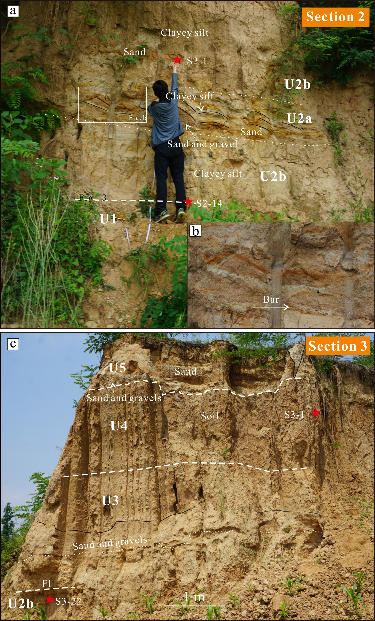
(color online) (a) Section 2 with U1, 2a and 2b, at almost the same elevation as the lower part of section 1. Unit 1 is exposed partly in this section -person for scale. (b) A bar in U2a with clear sedimentary structures is illustrated in the inset figure. Samples S2-7 to S2-14 belong to U2b; samples S2-1 to S2-6 belong to U2a. (c) Section 3 with U2b-5. Samples S3-1 to S3-8 belong to U4; samples S3-9 to S3-21 belong to U3, and sample S3-22 belongs to U2b. Fl: finely laminated silt layer (Miall, Reference Miall2006).
In sections 1 and 2, U2a shows a typical upward graded sequence of channel-filling sand with trough cross-bedding, to sand layers with planar cross-bedding, to horizontally bedded layers, ending with the deposition of the fine-grained U2b. In all other sections, U2 shows interbedded layers of sand, silt, and clay, and individual beds of U2a often interfinger laterally with clay beds of U2b. Individual beds of U2a have often an erosive lower boundary and may occur as local channels that erode into underlying clay beds of U2b by more than 1 m (e.g., section 5, Fig. 7). Especially at the base of such channels, the coarse sand is replaced by a massive gravel bed. The channel fill may even contain angular blocks of collapsed clay from the eroded U2b (section 5, Fig. 7). Samples from S1-2 to S1-11 in section 1 and from S1-2 to S2-6 in section 2 belong to U2a (Figs. 3, 4; Table S1).
The second subunit (U2b) is generally a stiff, blue-grey clayey silt that may reach a thickness of up to 3 m. It is mostly massive, but may also be finely sandy laminated or occur in tiny beds of sand interfingering with the sands of U2a. Also, thin sand lenses and very small, dispersed pebbles may occasionally occur. A piece of undetermined bone (2–3 cm size) was found in section 1 (Fig. 3c). The color of the fine-grained layers is mostly light-blueish grey but changes locally to dark grey and brown with associated roots and CaCO3 nodules (Fig. 2), pointing to soil formation. Such a paleosol is well developed at the top of U2 and occasionally shows a columnar prismatic structure (sections 3, 4a; Fig. 4c,6a). Another brown-black paleosol with prismatic structure due to desiccation cracking occurs at a lower level within the unit and is eroded by the sand channel mentioned above (sections 4b, 5; Figs. 6c, 7). At the base of the main clayey subunit in section 1, small-scaled involutions occur (10–35 cm amplitude) due to natural sedimentary loading (Fig. 3b). They occur especially in channel depressions. Sample S1-1 in section 1, samples from S2-7 to S2-14 in section 2, and sample S3-22 in section 3 belong to U2b (Figs. 3–5; Table S1).
(color online) Section 3a with U4-6. U5, with samples S3a-1 to S3a-11, is characterized by two dipping light brown soils alternating with silty deposits.

(color online) (a) Section 4a with U2a-2b. Height of section is 4 m. (b) Section 4b with U2b, 3 and 4, a short distance from section 4a. (c) Inset figure highlights the prismatic structure of the paleosol.

(color online) Section 5 with U2a-2b and U3. The scour structure in U2a has eroded the underlying beds by more than 1 m and indicates a local relatively higher energy environment within the floodplain. St: sand layer with trough cross-bedding; Sp: sand layer with planar cross-bedding (Miall, Reference Miall2006). Shovel is 75 cm long.

The overlying unit 3 (U3) is a ~2 to 4 m thick, horizontally laminated, grey-brown silt layer. Essentially, the unit consists of a series of at least 10 depositional cycles of alternating brown and grey beds, each 10–15 cm thick, in sections 1, 4b, 5, and 6 (Figs. 3a, 4c, 6b). The basal and middle part of this unit may be sandy (Fig. 4c) and even gravelly and obviously erosive at some places, while towards the top, the transition to the overlying soil (U4) is relatively gradual. Locally, a 30-cm thick dark-brown soil occurs at ~2 m above the base of the unit (section 3). Thin sand lenses or beds occur randomly within the unit, e.g., in section 3 (Fig. 4c). In section 4b, U3 shows alternations of thicker clayey silt and sand beds (15–50 cm), while the basal sand and gravel layer is 60 cm in thickness (Figs. 2, 6b). Samples from S3-9 to S3-21 in section 3 belong to U3 (Fig. 4; Table S1).
Unit 4 (U4) is distinguished as a separate and well recognizable unit. It is a strongly weathered dark brown paleosol with massive, prismatic structure that gradually developed on/from U3. It is best identified in sections 1, 3, 3a, 4b, and 6 (Fig. 2). It is > 2 m thick in sections 1 and 3, and becomes thinner (~20 cm) towards section 6 (Fig. 8a). Many concretions of Mn and CaCO3 and roots are present in the soil. In most sections, such as sections 1 and 3, the boundary to the overlying coarse unit (U5) is sharp and distinct, expressing the erosion of the paleosol U4. Samples from S3-1 to S3-8 in section 3 and sample S6-11 in section 6 belong to U4 (Figs. 4, 8; Table S1).
(color online) (a) Upper part of section 6 with units 4 and 5. Samples S6-1 to S6-10 belong to U5; sample S6-11 belongs to U4. (b) The lower part of section 6 (i.e., section 6b) with units 2 and 3. Shovel is 75 cm long.

Unit 5 (U5) consists of ~3 m of several cycles of alternating horizontal, parallel beds of sand at the bottom of the cycle and clay at the top of the cycle, individually 10–100 cm thick. It is best recognized in sections 1, 3, 3a, 6, and 7 (Fig. 2). But, in section 1, this unit is mainly composed of coarse sand made up of obliquely bedded, cm-thick horizontal laminae (Sh) and beds with massive structure (Sm) (Fig. 3a). In most parts, U5 is capped by a thin paleosol consisting of light brown clayey silt. Its heterogeneous lithology and structure are quite similar to U3. Greenish silty lenses contain strings of cemented aggregates of CaCO3. Occasional pebbles, which are normally at the bottom of the unit, are angular to subangular, and consist of quartz, flint, granite, and silt-clay pebbles. Quartz and granite could have a local origin, while the silt-clay pebbles obviously had their source in the adjacent units 3 and 4. All the samples from section 3a (S3a-1 to S3a-11), from S6-1 to S6-10 in section 6 and from S7-15 to S7-19 in section 7 belong to U5 (Figs. 5, 8, 9; Table S1).
Unit 6 (U6, described best from section 7; Fig. 9a) is 2–5 m thick and composed of alternating rather thick (60–150 cm) beds of light grey sandy silt and planar- or ripple-cross-bedded gravelly coarse sand (Sp, Sr), forming shallow bars. The sand bodies may show dipping laminae (~20°). Silty beds occur in lenses between the bars. The basal sediments of U6 consist of coarse sand (30-cm thick) with subangular to angular small pebbles. The basal boundary is sharp and erosive. As such, the lower part of the unit shows a clear fining-up sequence from channel gravel and coarse sand, grading into bars deposited by weaker flow, ending up in clayey-silty beds when flow was almost absent. This sequence is repeated a few times within the unit, although the coarse-grained channel deposits may be smaller scaled toward the top of the unit (Fig. 2). Similar to underlying units, U6 terminates with the formation of a light-brown, thin soil with root remnants (~0.3 m) (Fig. 9b). Samples from S7-1 to S7-14 in section 7 belong to U6 (Fig. 9; Table S1).
(color online) (a) Section 7 with U5–7. Samples S7-1 to S7-14 occur in the main lower part of U6 and samples S7-15 to S7-19 in the upper part of U5. Sp: sand layer with planar cross-bedding; Sr: sand layer with ripple cross-bedding; Fl: finely laminated silt layer (Miall, Reference Miall2006). Height of section is 7,5 m. (b) Paleosol at the top of U6 in section 7 with root remnants. Lens cap for scale.

Unit 7 (U7) is present at the top of section 7 and is characterized by an ~40-cm thick brown soil and a 60-cm thick grey clay with occasionally fine gravels. The basal boundary is erosive into the lower U6 (Fig. 9). No samples were taken from U7.
Lithostratigraphic correlations
An almost continuous exposure existed between sections 4, 5, 6, and 7, which enabled an easy correlation between the units in these sections. Correlation between these sections and sections 1, 2, and 3 is mainly based on the mostly well-expressed, prismatic, and dark-brown to brown paleosols in the massive clay layer at the top of U2 and within U4, and their relative elevations (Fig. 2).
Detailed correlation of specific beds is hampered by the frequent interfingering between sandy and clayey layers and by the presence of local soil horizons. This applies especially to lateral differentiation between units 2a and 2b. However, one relevant, generally occurring horizon was observed consisting of a distinct, gravelly sand layer occurring between rather thick clay beds. This sand layer is composed of inclined laminae expressing point bar deposits in section 2 and trough cross-bedding (St) in sections 4a, 5, and 6. In the latter sections, the basal boundary obviously eroded the underlying clay bed. This erosion is expressed locally in section 5 (Fig. 7) by an asymmetrically incised channel ~1 m deep. At the foot of the vertical channel side, eroded angular clay blocks were present between the channel filling sands (Fig. 7).
A further difficulty for detailed correlation is the similarity between paleosols in different units and the lateral variability of these paleosols, except for the thick and strong soil of U4.
Grain-size characteristics and depositional origin
Considering all samples, it may be concluded that three groups of grain-size populations may be distinguished by their modal values (Fig. 10): a fine clay fraction (1), a medium silt fraction (2), and a medium-to-coarse sand fraction (3). Even before detailed interpretation, from the unit descriptions and sedimentary structures, we can determine that the general depositional environment is that of a fluvial floodplain.
(color online) Grain-size distributions of some selected samples, showing three main classes: (1) a fine clay fraction (indicated with black arrows in both panels) with modal value around 0.8–1 μm; (2) a silt group consisting of a coarse clay to very fine silt subfraction with modal values around 5–8 μm (the light blue arrows in both panels), a fine-medium silt subfraction of 10-16 μm (dark blue arrow in panel a), a medium-coarse silt subfractions of 21–28 μm (light green arrow in panel a) and 28–37 μm (dark green arrow in panel b); and (3) a medium-to-coarse sand fraction with modal value 225–800 μm (orange arrow in both panels). For interpretation of the individual classes, see main text.

The finest fraction (1) is common in all samples, although always in a very small amount (< 2%). It never occurs as an individualized fraction and thus its exact modal size is difficult to determine from the distribution curves. However, in all samples, this modal value seems to be around 0.8–0.9 μm. Two origins may be possible. The first possible origin is of chemical or biochemical pedogenic origin, and is characterized by a modal size of about 0.2–0.4 μm (Sun et al., Reference Sun, Bloemendal, Rea, Vandenberghe, Jiang, An and Su2002; Reference Sun, Zhang, Han, Zhang, Yi, Li, Wang, Wu and Li2011), which is slightly smaller than fraction (1) at the Jinxing site. The second possible origin is a purely lacustrine deposit in completely standing water, although this fraction is usually coarser (1–2.5 μm; Vandenberghe et al., Reference Vandenberghe, Sun, Wang, Abels and Liu2018). An in situ pedogenic origin is contradicted by the fact that the relative amount of this fine clay fraction (1) does not increase substantially in clearly developed soils, e.g., sample S3-2 (Fig. 10a). Therefore, we conclude for deposition of reworked fine sediment, for instance, strongly weathered sediment (possibly also of pedogenic origin) that was hydrodynamically sorted in the standing water of abandoned pools on the floodplain.
The coarsest fraction (3) is also very common, except for some specific beds. It is the dominant fraction in the sandy beds of all units, e.g., S1-2 (Fig. 10b). Its modal size varies between 225–800 μm, often with associated gravels. The sedimentary structures (e.g., ripple and trough cross-bedding) point to deposition in channels, bars, ripples, and sand sheets. Thus, a fluvial origin is beyond doubt. Apart from U1, the highest energy conditions occur in U2a, where the sand content is > 60%, with an average modal grain size of 400 μm or more. These grain-size characteristics are linked with a channel facies and/or the relatively high-energy floodplain. Sandy beds occur in most units other than U1 as isolated bodies or sheets that are deposited as bars or sheets of varying height, width and magnitude.
The silt fraction (2) is more complex and, in several units, may be subdivided into subfractions of 5–8 μm, 10–16 μm, 21–28 μm, and 28–37 μm fractions. The two latter subfractions are similar to sediment type 1.b in Vandenberghe (Reference Vandenberghe2013), and represent a continuum in the commonly recognized medium-silty windblown loess that is deposited from near-surface to low-suspension clouds (Prins and Vriend, Reference Prins and Vriend2007; Vandenberghe, Reference Vandenberghe2013). These silt subfractions were preferably supplied by the winter monsoon (Vandenberghe et al., Reference Vandenberghe, An, Nugteren, Lu and Huissteden1997). The fine-grained subfractions (5–8 μm;10–16 μm) are only present in minor amounts in a few sections and units, and are often difficult to individualize and quantify. They are mostly visible as a ‘shoulder’ or asymmetric bulge of the frequency distribution curves, e.g., sample S3-18 (Fig. 10b) and S3-2 (Fig. 10a). At least the 10–16 μm fraction corresponds with loess type 1.c.1 (Vandenberghe, Reference Vandenberghe2013), and is interpreted as background dust transported in high-suspension clouds over long distances mainly by westerlies (Sun et al., Reference Sun, Bloemendal, Rea, An, Vandenberghe, Lu, Su and Liu2004; Prins et al., Reference Prins, Vriend, Nugteren, Vandenberghe, Lu, Zheng and Weltje2007; Vriend et al., Reference Vriend, Prins, Buylaert, Vandenberghe and Lu2011). Considering the general fluvial setting of the entire sediment series, it is logical to assume that the original loess was transported by the river and subsequently redeposited in an alluvial environment. As has been shown before (Vandenberghe et al., Reference Vandenberghe, de Moor and Spanjaard2012, 2018; Yang et al., Reference Yang, Wang, Van Balen, Prins, Wang, van Buuren and Lu2019), the original mean grain-size distribution does not change substantially by this reworking process.
The sediment fraction 21–37 μm, e.g., sample S7-7 (Fig. 10b), seems to be a bit finer-grained than on the Chinese Loess Plateau, missing grain sizes larger than 40 μm but with sizes as fine as 21 μm. Such a fining towards the south and southeast of the loess depositional region has been reported before (Liu, Reference Liu1985; Ding et al.,Reference Ding, Sun, Rutter, Rokosh and Liu1999; Nugteren and Vandenberghe, Reference Nugteren and Vandenberghe2004; Nugteren et al., Reference Nugteren, Vandenberghe, Van Huissteden and An2004; Prins et al., Reference Prins, Vriend, Nugteren, Vandenberghe, Lu, Zheng and Weltje2007; Vriend et al., Reference Vriend, Prins, Buylaert, Vandenberghe and Lu2011; Zhang et al., Reference Zhang, Lu, Jiang, Vandenberghe, Wang and Cosgrove2012, and references therein).
As has been pointed out by Vandenberghe et al. (Reference Vandenberghe, Sun, Wang, Abels and Liu2018), the finer subfraction 5–8 μm may have a twofold origin: a background windblown loess (as fraction 1.c.2 in Vandenberghe, Reference Vandenberghe2013) comparable with the 10–16 μm fraction, but a pedogenic origin is also possible. In fact, we partly favor the latter hypothesis, because the fraction 5–8 μm occurs especially in the macroscopically observed paleosols, e.g., in the paleosols of U5 in section 7 and in U4 in sections 3, 3a, and 6. It is even represented as individualized peaks in the upper soil of U4 in section 6 (sample S6-11), and in the soils of U5 in section 3a (samples S3a-6 and 8) and section 3 (sample S3-2) (Fig. 10a). Thus, it may be concluded that the paleosols usually show a slight enrichment in this fine-grained fraction of 5–8 μm. In contrast, there are a few samples where this fraction 5–8 μm also occurs without macroscopic soil, e.g., in U3 of section 3 (samples S3-18) and U2b in section 2 (samples S2-12) (Fig. 10b). In such cases, we hypothesize a redeposition of aeolian background loess, combined with redeposited pedogenic loess.
All individual grain-size data are provided in Supplementary figure S1, and the main grain-size parameter values of the individual units are summarized in Table S1 (U-ratio and sand %, silt %, clay %, mean and modal values). The supplementary text describes in detail the grain-size characteristics of each unit.
Sedimentary facies
Different facies within the generally fluvial environment may be distinguished according to their energy conditions: a high-energetic channel facies (a) and two floodplain facies (b and c).
Facies a.
This channel facies, only represented by U1 (section 2), expresses the highest energy conditions (Figs. 2, 4a). The large cobbles illustrate these energy-rich conditions in the river channel. Due to its sediment size, it may be called a ‘gravel-bed braided river’ after Miall (Reference Miall2006). The diverse petrographic composition of the gravel points to a rather far provenance, and thus a former course of the Hanjiang River. Situated 7–18 m above the modern floodplain level, it corresponds with terrace T3 of the Hanjiang River at similar level, e.g., the sections at Baoshan (Van Buuren et al., Reference Van Buuren, Prins, Wang, Stange, Yang and van Balen2020), and the Longgangsi-1 and Yaochangwan sites in the Hanzhong Basin (Sun et al., Reference Sun, Lu, Wang, Yi, Li, Bahain, Voinchet, Hu, Zeng and Zhang2017).
Facies b.
This relatively high-energy floodplain facies is typically expressed by U2a in sections 1 and 2 (Fig. 2). It represents a laterally shifting river system consisting of alternating small-sized secondary channels and lateral or longitudinal bars in a floodplain environment. Fine gravel and sand were supplied by relatively high floods in an overbank position. Pebbles in this facies never reach gravel size as within facies a, and the dimensions of the channels are relatively minor. The channels are often eroded (laterally and vertically up to 1 m deep) into previously formed fine-grained floodplain sediments. These channels are filled with gravelly coarse sand, reaching modal values of up to 800 μm (Fig. 10b). The bars also consist of medium to coarse sand, but in phases of calm flow, they interfingered with the silty sediments from facies c, e.g., U2b in section 2 (Fig. 4a). Because of their small size in an overbank position, we call these channels ‘secondary’. Such secondary channels are also present within U3 in sections 1, 3, 3a, 4b, and at the base of the units U5-7 in section 1, 3, 3a, 6, and 7 (Fig. 2).
It also should be noted that the presence of angular grains and gravels in U6 and U7 may point to the addition of sediment from more local provenance than in facies a.
Facies c.
This low-energy floodplain facies characterizes units U2b, U4, and the upper parts of U5–U7. This is a finer-grained continuation of facies b, pointing to a generally calmer depositional environment. Sediments were transported to, and settled down in, relatively low parts of the floodplain (pools) with reduced or absent channeling, and occasionally terminating in emergent phases and soil formation. The fine-grained deposits often occur in horizontal parallel sheets, sometimes as finely laminated sands and silts, or as bedded layers of up to 20-cm thick alternating sand and silt. In many cases, they may also appear in massive layers. U2b is the most typical example of this facies that appears especially in the middle and upper parts of units 3–7 (Fig. 2). The transition between facies b and c may be gradual.
The grain-size distributions of the fine-grained components are dominated by silts with mean modal value of ~30 μm, which corresponds to that of typical primary monsoonal loess transported by low suspension clouds. Obviously, these sediments are not primary wind deposits in the study site, rather, they were reworked in a fluvial setting. The sheets of silty deposits show often bi- or trimodality of grain size, meaning they may contain a substantial amount of sand and fine silt next to the predominating silt component, for example, U2b in section 1 (sample S1-1) (Fig. 10b). Occasionally, a small amount of fine-grained, background loess (5–8 μm) is included.
U-ratios in U2b are relatively high. In combination with ~25% sand content, this points to relatively strong flow, even in the case of overbank flooding. At times, flow stopped entirely and left some pools. A constant but small amount of fine clay (0.8–0.9 μm) was subsequently deposited in the standing water of these pools (Vandenberghe et al., Reference Vandenberghe, Sun, Wang, Abels and Liu2018; Wang et al., Reference Wang, Ma, Yi, Vandenberghe, Dai and Lu2019). A greyish, clayey-silty bed located between sections 1 and 2 is interpreted as an oxbow lake fill by its occurrence between point bar deposits of U2a (Fig. 11). Ultimately, soils ~30 cm to 3 m thick and of relatively wide extent (e.g., soils in U4) often developed, most typically at the top of this facies. Locally, thinner soils developed in high positions during phases of decreasing flow with low sediment supply.
(color online) An example of oxbow lake deposits in U2 between sections 1 and 2. Height of section is 15 m.

The successions within all units show a similar and recurrent sedimentary composition and a clear cyclicity from high energy to low energy floodplain sedimentation terminating with stability as shown by soil formation. In places, deposition within the individual units was interrupted temporarily by additional short phases of stability.
A peculiar sedimentary structure in sections 3a (Fig. 5) shows two dipping light-brown soils alternating with silty deposits in U5. The upper of the two soils, with thickness of 1.5 m, climbs for ~2.5 m, then merges with the upper soil of unit U6. The lower of the two soils in U5 occurs only at this particular place and in the middle of that U5. As a result, U5 thickens to up to 3 m. The grain-size properties of the soils do not differ from those of beds in which they formed, including a small but clear presence of coarse sand (modal value > 500 μm) and occasionally pedogenically weathered very fine silt (modal value ~6–7 μm), e.g., samples S3a-6 and S3a-8, (Fig. 10a).
The genetic interpretation of this landform is not straightforward. The homogeneous sedimentary structure in sections 3-3a is an argument for an aeolian origin, but the removal of fine-medium silt by wind to form dunes is not very common. River bars in facies b are much smaller sized and consist of coarse sands such as in section 1-2. However, the granulometric similarity (Fig. 10a) of the deposits with the fine-grained beds in facies c as well as the admixture of a coarse-grained fraction provisionally indicate they were deposited in water rather than by wind. Therefore, we favor the fluvial hypothesis of deposition at the front of or adjacent to an elevated and dipping sediment body in the riverbed (e.g., a bar or levee), alternating with dry conditions enabling soil formation. In this sense, the deposition process is similar to that of facies c, and the only difference would be that it did not develop in horizontal sheets but in a tilted position.
The paleosols
The soils, especially the upper soils of U2b and U4, are characterized by their dark to light brown color, a slight clay illuviation, Fe and/or Mn staining, and a prismatic structure. In several places, precipitations of CaCO3 nodules (Fig. 2) and manganese and iron oxide have been observed. According to the FAO World reference base for soil resources (IUSS Working Group WRB., 2015), the soils can be described as Bt to Bw horizons of luvic cambisols. The intensity and frequency of soil formation and the relative amount of reworked background loess seem to increase towards the upper part of the exposure. Except for U4 paleosols, the illuviation process remained relatively weak, possibly due to the limited time on the floodplain between frequent floods. The soil layers with iron-manganese concretions in the floodplain series could indicate slightly stronger pedogenesis during an interval with weak hydrodynamic but warm and stable conditions in the monsoonal floodplain.
DISCUSSION AND SYNTHESIS: FLOODPLAIN GEOMORPHOLOGY AND SEDIMENTOLOGY, RESPONSE TO MONSOONAL CLIMATE VARIABILITY
The vertical sedimentary sequence and lateral evolution show a high range of changing energy conditions. The highest energy is represented by channel facies a, and occurs at the base of the sediment series. During deposition of facies a, sediment supply exceeded transport capacity, resulting in gravel aggradation. The depositional environment then changed to a floodplain environment with much smaller sized, laterally migrating and vertically incising secondary channels in relatively high-energy conditions (facies b), alternating with deposition on a floodplain with low energy with phases of stability allowing for soil formation (facies c). In the terminology of Nanson and Croke (Reference Nanson and Croke1992), the resulting floodplain deposits could be called ‘medium-energy non-cohesive floodplains’ for facies b, and ‘low-energy cohesive floodplains’ for facies c.
The general sedimentary setting, structures, and the grain-size analyses of facies b-c all point to a floodplain environment with varying hydrodynamic conditions in which reworked aeolian sediments (mainly fresh and some weathered loess) were redeposited. Major high-energy flooding events represented by meter-scale deposits occurred at least four or five times within U2–, U3-4, U5 and in the lower parts of units 6 and 7, as well as at smaller scales within U2 and U7, all together representing at least 10 flooding events (Fig. 2). Sedimentary conditions alternated swiftly and periodically from: (1) relatively high energy flooding events to (2) calm, low energy flooding events, with fluvial and/or fluvio-aeolian sedimentation, resulting in stagnant pool formation with lacustro-aeolian sedimentation in oxbow lakes and swales between bars, and finally to (3) a completely stable situation with a pause in deposition and subsequent soil development until the next phase of floodplain deposits that eroded into the previous soil formation in varying degrees.
The small channels on the floodplain are characterized by lateral migration and the formation of likely lateral bars that are indicative of wandering rather than straight channels. However, the sedimentary conditions on the floodplain varied rapidly from active channeling to floodplain lakes and swamps and finally to relatively dry phases of stability, typical for a monsoonal climate with well-pronounced seasonality. This rapidly evolving floodplain environment is comparable with the morphology of the present-day Hanjiang River (Fig. 1c), more particularly, a wandering-meandering river (Miall, Reference Miall2006). No paleoenvironmental indications are available for facies a, but by analogy with similar neighboring deposits (e.g., Baoshan site, Van Buuren et al., Reference Van Buuren, Prins, Wang, Stange, Yang and van Balen2020) and the basal terrace deposits of the Huangshui River (Vandenberghe et al., Reference Vandenberghe, Wang and Lu2011; Wang et al., Reference Wang, Vandenberghe, Yi, Balen and Lu2015), facies a points to active channels in much higher energy environment than during facies b and c deposition, more particularly, a braided river system.
No specific age and paleoclimatic information for the Jinxing sediment sequence is currently available. Terrace gravels at the Baoshan site date were dated to 0.6 ± 0.14 Ma using terrestrial cosmogenic nuclides (Van Buuren et al., Reference Van Buuren, Prins, Wang, Stange, Yang and van Balen2020), and because these terraces correspond with channel facies a at this study site at Jinxing, we may assume a similar age for the terrace gravels at Jinxing. With regard to climatic conditions, the common opinion is that the basal braided river deposits (facies a; U1) may be attributed to a glacial period (e.g., Kasse, Reference Kasse, Benito, Baker and Gregory1998; Mol et al., Reference Mol, Vandenberghe and Kasse2000; Vandenberghe and Woo, Reference Vandenberghe and Woo2002; Van Huissteden et al., Reference Van Huissteden, Vandenberghe, Gibbard, Lewin, Elias and Mock2013; Wang et al., Reference Wang, Vandenberghe, Yi, Balen and Lu2015, and references therein). In contrast, the overlying floodplain deposits and paleosols in a calmer meandering-wandering river system (facies b and c) are similar to the present -day, interglacial monsoonal river pattern. Considering the age of nearby fluvial terrace gravels at Baoshan (Van Buuren et al., Reference Van Buuren, Prins, Wang, Stange, Yang and van Balen2020), the cold period during which the terrace gravels at Jinxing were formed (U1) may be the ice age corresponding with L6 in the loess series of the Central Loess Plateau (Nugteren et al., Reference Nugteren, Vandenberghe, Van Huissteden and An2004) and MIS 16 (Vandenberghe, Reference Vandenberghe2000), and the following interglacial period with floodplain accumulation (U2–U7) may correspond with the long interval of paleosol formation of S5 and MIS13-15 (Vandenberghe, Reference Vandenberghe2000).
The transition from active channel deposits to floodplain formation and soils may correspond with the starting incision of the main channel and the associated abandonment of the terrace by this main channel. More specifically, this morphological transition should correspond with the transition from a cold to a warm climate with monsoonal rainfall and associated vegetation cover (Vandenberghe, Reference Vandenberghe2015; Wang et al., Reference Wang, Vandenberghe, Yi, Balen and Lu2015; Daley and Cohen, Reference Daley and Cohen2018, and references therein). During this incision phase of the cold-warm transition and the subsequent warm interglacial, the abandoned terrace was invaded only at high stages of the river, and recorded flood deposits of different lithologies due to different flood intensities. Such a succession seems to be analogous to other terraces in the Hanzhong Basin and Huanghe (Yellow River) catchment (Pan et al., Reference Pan, Hu, Wang, Vandenberghe and Hu2011; Vandenberghe et al., Reference Vandenberghe, Wang and Lu2011; Wang et al., Reference Wang, Vandenberghe, Yi, Balen and Lu2015; Gao et al., Reference Gao, Li, Liu, Wu, Li, Zhao, Li, Guo, Liu, Pan and Jia2020). The style of alluvial architecture (overall dominant, vertical fine-grained accretion with small bars, small-scale cut-and-fill channels, distinct channel migration, and bank erosion) shows many similarities with the active meandering Rio Bermejo in Argentina described by Smith et al. (Reference Smith, Best, Leroy and Orfeo2016). The changes and cyclicity within the floodplain may simply have been caused by the impact of internal fluvial dynamics (e.g., Schumm, Reference Schumm1977; Vandenberghe et al., Reference Vandenberghe, Wang and Lu2011; Wang et al., Reference Wang, Vandenberghe, Yi, Balen and Lu2015; Gao et al., Reference Gao, Wang, Yi, Vandenberghe, Gibling and Lu2018). Theoretically, small climatic changes cannot be excluded, e.g., in monsoon precipitation, but there is no independent evidence except soil formation for climatic changes during the floodplain phase.
The lower part of the fine-grained deposits covering the terrace gravels at Baoshan (0–9.5 m above the terrace gravels) are also interpreted as floodplain deposits (Van Buuren et al., Reference Van Buuren, Prins, Wang, Stange, Yang and van Balen2020). In contrast, the upper part of the fine-grained deposits covering the terrace gravels at Baoshan (from 9.5–30 m above the terrace gravels) seems to be clearly more homogeneous than the deposits of facies b and c at Jinxing, and therefore, an aeolian interpretation is preferred (Van Buuren et al., Reference Van Buuren, Prins, Wang, Stange, Yang and van Balen2020). This may point to a lateral transition from an aeolian (Baoshan) to an alluvial (Jinxing) setting for the sediments >9.5 m above the terrace gravels (roughly corresponding with deposition of U5 to U7 according to their height positions), and a narrowing of the floodplain. An aeolian interpretation is also favored for the ‘Xiashu loess’ slightly more to the east, in the region of the Huaiu and Yangtze valleys (Jiang et al., Reference Jiang, Hao, Peng and Qiao2020).
CONCLUSIONS
A 20-m thick fluvial sediment series is described from the Hanzhong Basin, central China, with monsoonal climate conditions. It is situated in a terrace position and is composed of diverse sedimentary facies, from a gravelly, high energy channel to a relatively low energy floodplain. The vertical and lateral sedimentary variations in the floodplain show four to five major sedimentary cycles, and more than ten cycles in total, with gradually changing hydrodynamic conditions from secondary gravel-bearing channels, sand channels, sand bars, and sand ripples, to silty and clayey pools and swamps, and ultimately, paleosols. The primary origin of the fine-grained sediment is aeolian loess, but overall it has been reworked by fluvial processes. During a cold period with strong winter monsoon, gravel aggraded in the main channel, and during the transition to a next warm climate with an increasing summer monsoon, the main channel gradually incised. During the latter transitional phase, the high/low energy floodplain deposits and soil layers stacked as a response to a varied frequency and magnitude of flooding and sediment supply, possibly related to varied intensity of monsoonal rainfall and related vegetation evolution, or simply to internal evolution. Subsequently, the river continued to incise, abandoning the described floodplain and thus transforming it into a terrace.
ACKNOWLEDGMENTS
This research is supported by the National Natural Science Foundation of China (41971005, 41522101), the National Key Research and Development Program (grant number 2016YFA0600500), the Major Program of National Social Science Foundation of China (grant number 19ZDA225), and the Royal Netherlands Academy of Arts and Sciences (Chinese Exchange Program, grant number 530-5CDP07). We thank Zhengchen Li for his help during the fieldwork and laboratory analyses. The authors are grateful for the constructive comments of reviewers and editors.
SUPPLEMENTARY MATERIAL
The supplementary material for this article can be found at https://doi.org/10.1017/qua.2020.107.


 Open access