


1. Introduction
A simple closed curve on a compact closed surface,
 $S_g$
, of genus
$S_g$
, of genus
 $g \geq 2$
is called essential if it does not bound a disc. As such, going forward a “curve in
$g \geq 2$
is called essential if it does not bound a disc. As such, going forward a “curve in
 $S_g$
” will mean an essential simple closed curve in
$S_g$
” will mean an essential simple closed curve in
 $S_g$
. Two curves in
$S_g$
. Two curves in
 $S_g$
intersect coherently if all the intersection points have the same orientation provided that the two curves are oriented. Note that it does not depend on the choice of the orientation of the curves. Two curves are in minimal position if the number of intersections of these curves is the minimal within the curves isotopy classes. It is a simple observation that a coherently intersecting pair are already intersecting minimally within their isotopy classes. Thus, for coherently intersecting curves this convenience allows us to drop the distinction between working with a curve pair and their isotopy classes. A pair of curves in
$S_g$
intersect coherently if all the intersection points have the same orientation provided that the two curves are oriented. Note that it does not depend on the choice of the orientation of the curves. Two curves are in minimal position if the number of intersections of these curves is the minimal within the curves isotopy classes. It is a simple observation that a coherently intersecting pair are already intersecting minimally within their isotopy classes. Thus, for coherently intersecting curves this convenience allows us to drop the distinction between working with a curve pair and their isotopy classes. A pair of curves in
 $S_g$
is filling if over all representatives from their isotopy classes their complement in
$S_g$
is filling if over all representatives from their isotopy classes their complement in
 $S_g$
is a collection of discs.
$S_g$
is a collection of discs.
Let
 $\alpha, \beta \subset S_g$
be a filling pair. We call
$\alpha, \beta \subset S_g$
be a filling pair. We call
 $(\alpha, \beta)$
a minimally intersecting filling pair if the intersection number,
$(\alpha, \beta)$
a minimally intersecting filling pair if the intersection number,
 $| \alpha \cap \beta |$
, is minimal among all filling pairs on
$| \alpha \cap \beta |$
, is minimal among all filling pairs on
 $S_g$
. For Euler characteristics reasons,
$S_g$
. For Euler characteristics reasons,
 $| \alpha \cap \beta | \geq 2g-1$
. Additionally, for Euler characteristic reasons a minimally intersecting filling pair would have the property that
$| \alpha \cap \beta | \geq 2g-1$
. Additionally, for Euler characteristic reasons a minimally intersecting filling pair would have the property that
 $S_g \setminus (\alpha \cap \beta)$
is a single open disc. For
$S_g \setminus (\alpha \cap \beta)$
is a single open disc. For
 $g=1$
this lower bound is geometrical realisable with a meridian-longitude pair. For
$g=1$
this lower bound is geometrical realisable with a meridian-longitude pair. For
 $g=2$
, an exhaustive search of the finite possibilities for a filling pair intersecting 3 times establishes that none exist and that at least 4 intersections is needed. However, Aougab and Huang showed in [
Reference Aougab and Huang1
] that for all
$g=2$
, an exhaustive search of the finite possibilities for a filling pair intersecting 3 times establishes that none exist and that at least 4 intersections is needed. However, Aougab and Huang showed in [
Reference Aougab and Huang1
] that for all
 $g \geq 3$
there exists filling pairs of curves whose intersection achieves the
$g \geq 3$
there exists filling pairs of curves whose intersection achieves the
 $2g-1$
minima. (More recently, also see [
Reference Jeffreys8, Reference Nieland10
].) Moreover, the minima can be obtained with
$2g-1$
minima. (More recently, also see [
Reference Jeffreys8, Reference Nieland10
].) Moreover, the minima can be obtained with
 $\alpha$
and
$\alpha$
and
 $\beta$
intersecting coherently shown in [
Reference Aougab, Menasco and Nieland2
], so the set of minimally intersecting filling pairs is non-empty for
$\beta$
intersecting coherently shown in [
Reference Aougab, Menasco and Nieland2
], so the set of minimally intersecting filling pairs is non-empty for
 $g \geq 3$
.
$g \geq 3$
.
The construction of minimally intersecting filling coherent pairs in [ Reference Aougab, Menasco and Nieland2 ] largely utilises the algebraic techniques coming from the symmetric groups. In this paper we give an alternative geometric construction coming from simple cut-and-paste techniques. Our construction allows one to rapidly construct by hand such filling pairs for any genus.
1·1. Coherent filling pairs and origamis.
For a filling pair of curves,
 $\alpha, \beta \subset S_g$
, positioned in their isotopy classes so as to have
$\alpha, \beta \subset S_g$
, positioned in their isotopy classes so as to have
 $| \alpha \cap \beta |$
being minimal, the 4-valent graph,
$| \alpha \cap \beta |$
being minimal, the 4-valent graph,
 $\alpha \cup \beta = C^1 \subset S_g$
, can be thought of as the 1-skeleton of a 2-dimensional CW structure on
$\alpha \cup \beta = C^1 \subset S_g$
, can be thought of as the 1-skeleton of a 2-dimensional CW structure on
 $S_g$
. The dual graph,
$S_g$
. The dual graph,
 $\widehat{C}^1 \subset S_g$
, is also the 1-skeleton of a CW structure that has every 2-cell being a quadrilateral containing a single 0-cell, an intersection point from
$\widehat{C}^1 \subset S_g$
, is also the 1-skeleton of a CW structure that has every 2-cell being a quadrilateral containing a single 0-cell, an intersection point from
 $\alpha \cap \beta (\subset C^1)$
. Giving each such quadrilateral 2-cell a
$\alpha \cap \beta (\subset C^1)$
. Giving each such quadrilateral 2-cell a
 $[0,1] \times [0,1]$
Euclidean square structure, we obtain a square tiling of
$[0,1] \times [0,1]$
Euclidean square structure, we obtain a square tiling of
 $S_g$
. If we have
$S_g$
. If we have
 $\alpha$
and
$\alpha$
and
 $\beta$
intersecting coherently then an orientation assignment to these two curves gives a natural way to assign the “right-side, left-side, bottom, top” categories to the four boundary 1-cells of each square tile. It follows that each 1-cell of
$\beta$
intersecting coherently then an orientation assignment to these two curves gives a natural way to assign the “right-side, left-side, bottom, top” categories to the four boundary 1-cells of each square tile. It follows that each 1-cell of
 $\widehat{C}^1$
is either a left/right side gluing or a bottom/top gluing of two square tiles. That is, we have a [1, 1]-origami for
$\widehat{C}^1$
is either a left/right side gluing or a bottom/top gluing of two square tiles. That is, we have a [1, 1]-origami for
 $S_g$
. Specifically, we have the following result from the literature.
$S_g$
. Specifically, we have the following result from the literature.
Theorem 1·1 ([
Reference Chang, Jin and Menasco6, Reference Jeffreys9
]). A coherent filling pair of curves naturally corresponds to a [1, 1]-origami on
 $S_g$
.
$S_g$
.
The Euclidean square tiles of an origami gives us a flat geometry except at finitely many branched points—one for each 2-cell of the original CW structure—which correspond to the points where the corners of the tiles are adjoined. An origami coming from a coherent filling pair has one horizontal cylinder and one vertical cylinder—hence, a [1, 1]-origami. Figure 1 ([
Reference Aougab, Menasco and Nieland2
, figure 1]) illustrates such a [1, 1]-origami for
 $S_3$
. (Depending on which notion of equivalency is used, Figure 1 can be considered the unique [1, 1]-origami up to labelling for genus three [
Reference Aougab, Menasco and Nieland2, Reference Chang5
]. See Remark 5·5.)
$S_3$
. (Depending on which notion of equivalency is used, Figure 1 can be considered the unique [1, 1]-origami up to labelling for genus three [
Reference Aougab, Menasco and Nieland2, Reference Chang5
]. See Remark 5·5.)
The left illustrates a filling pair (which is
 $C^1$
), the associated square tiles, and the left/right bottom/top gluing assignment for the origami structure. The right illustrates its geometric realisation on
$C^1$
), the associated square tiles, and the left/right bottom/top gluing assignment for the origami structure. The right illustrates its geometric realisation on
 $S_3$
. The left’s numeric labelling of red/blue (online edtion) or gray/black (print edtion) edges of
$S_3$
. The left’s numeric labelling of red/blue (online edtion) or gray/black (print edtion) edges of
 $C^1$
correspond to the numeric labelling of the right. Note that there is exactly one branched point since there is a single component of
$C^1$
correspond to the numeric labelling of the right. Note that there is exactly one branched point since there is a single component of
 $S_3 \setminus (\alpha \cup \beta)$
.
$S_3 \setminus (\alpha \cup \beta)$
.

The flat metric on
 $S_g$
coming from the Euclidean square tilings on
$S_g$
coming from the Euclidean square tilings on
 $S_g$
induces a horizontal foliation on each individual square tile that can be extended to a measured singular foliation
$S_g$
induces a horizontal foliation on each individual square tile that can be extended to a measured singular foliation
 $\mathcal{F}$
on
$\mathcal{F}$
on
 $S_g$
. A fundamental theorem of Hubbard–Masur associates a unique quadratic differential to this horizontal foliation and, therefore, to the square-tiling [
Reference Hubbard and Masur7
]. An origami of S can thus be interpreted as a point in the space of unit-area quadratic differentials. When
$S_g$
. A fundamental theorem of Hubbard–Masur associates a unique quadratic differential to this horizontal foliation and, therefore, to the square-tiling [
Reference Hubbard and Masur7
]. An origami of S can thus be interpreted as a point in the space of unit-area quadratic differentials. When
 $\mathcal{F}$
is orientable, the origami supports the structure of a translation surface, and the associated quadratic differential will be the square of an Abelian differential.
$\mathcal{F}$
is orientable, the origami supports the structure of a translation surface, and the associated quadratic differential will be the square of an Abelian differential.
1·2. Outline.
In Section 2·1, we introduce the cut-and-paste surgery operations that we will be utilising. These surgery operations have the property that, starting with a coherent filling pair of curves on a torus, we will trade an increase in the genus of the surface for a reduction in the number of discs in the complement of the filling pair. A minimally intersecting filling pair will be realised when the number of disc components is reduced to one.
In Section 2·2, we introduce our initial combinatorial tool for determining when the number of disc components is reduced to one—the A-graph. Specifically, we have Theorem 2·1 which states that when an A-graph is a tree, the resultant filling pair will be minimal. This theorem implies Corollary 2·2 which says that minimal coherent filling pairs exist for all
 $S_g, \ g \geq 3$
. (Again, also see [
Reference Aougab, Menasco and Nieland2, Reference Jeffreys9
] for alternative proofs.) In Section 3 we supply the proof of Theorem 2·1.
$S_g, \ g \geq 3$
. (Again, also see [
Reference Aougab, Menasco and Nieland2, Reference Jeffreys9
] for alternative proofs.) In Section 3 we supply the proof of Theorem 2·1.
In Section 4 we discuss more general surgery constructions. In Section 5 we give several examples that illustrate some of the pathologies that can occur with such generalisations. The main aim of these examples is to show the difficulties that occur when trying to use a count of the number of tree graphs as an estimate for the growth rate of minimal coherent filling pairs as a function of genus. For this discussion we introduce the H-graph, a tool that is used to determine when a tree graph corresponds to a surgery construction that yields a minimal coherent filling pair.
In Section 6, we examine when and how [1, 1]-origamis coming from the constructions in [ Reference Aougab, Menasco and Nieland2 ] and [ Reference Jeffreys9 ] are obtained by our geometric construction.
Finally, in Section 7 we generalise the construction to
 $S_{g,p}$
, oriented surfaces of genus g with p punctures. In the setting of punctures surfaces the complement of a filling pair of curves is a collection of discs and once punctured discs.
$S_{g,p}$
, oriented surfaces of genus g with p punctures. In the setting of punctures surfaces the complement of a filling pair of curves is a collection of discs and once punctured discs.
Notation. Throughout this paper we will use
 $S_g$
to denote a closed orientable surface of genus, g.
$S_g$
to denote a closed orientable surface of genus, g.
 $S_{g,p,b}$
will denote a closed orientable surface of genus g with p marked points or punctures, and b boundary components. We allow for the case where
$S_{g,p,b}$
will denote a closed orientable surface of genus g with p marked points or punctures, and b boundary components. We allow for the case where
 $b=0$
by using the notation,
$b=0$
by using the notation,
 $S_{g,p}$
.
$S_{g,p}$
.
 $\partial Y$
denotes the boundary of a compact surface, Y.
$\partial Y$
denotes the boundary of a compact surface, Y.
 $|X|$
denotes the cardinality of the set X.
$|X|$
denotes the cardinality of the set X.
2. Surgeries on coherent filling pairs on
 $S_1$
$S_1$

Our strategy for constructing a minimal coherent intersecting filling pair for a genus
 $g \geq 3$
oriented closed surface is to start with a coherent intersecting filling pair of curves,
$g \geq 3$
oriented closed surface is to start with a coherent intersecting filling pair of curves,
 $(\alpha ,\beta)$
, on the torus,
$(\alpha ,\beta)$
, on the torus,
 $S_1$
, that intersect g-times. (Using the ordered 2-tuple,
$S_1$
, that intersect g-times. (Using the ordered 2-tuple,
 $\langle m, l \rangle (=\langle {\rm meridian, longitude} \rangle) \in \mathbb{Z} \times \mathbb{Z}$
that specifies curve isotopy classes on
$\langle m, l \rangle (=\langle {\rm meridian, longitude} \rangle) \in \mathbb{Z} \times \mathbb{Z}$
that specifies curve isotopy classes on
 $S_1$
, the reader might think of
$S_1$
, the reader might think of
 $\alpha \subset S_1$
as being the
$\alpha \subset S_1$
as being the
 $\langle 0,1 \rangle$
curve and
$\langle 0,1 \rangle$
curve and
 $\beta \subset S_1$
being the
$\beta \subset S_1$
being the
 $\langle g,1 \rangle$
curve.) Our construction requires that we consider two cases, when g is odd and when g is even. For the odd case, through a simple surgery operation on the graph,
$\langle g,1 \rangle$
curve.) Our construction requires that we consider two cases, when g is odd and when g is even. For the odd case, through a simple surgery operation on the graph,
 $\alpha \cup \beta \subset S_1 $
, we will add in
$\alpha \cup \beta \subset S_1 $
, we will add in
 $g-1$
new vertices. Initially,
$g-1$
new vertices. Initially,
 $S_1 \setminus (\alpha \cup \beta)$
has g disc components. For later reference we state our strategy as follows.
$S_1 \setminus (\alpha \cup \beta)$
has g disc components. For later reference we state our strategy as follows.
Each surgery decreases the number of disc components by one while increasing the genus of the resulting surface by one.
The genus of the final surface will be g and there will be exactly one disc component in the complement of the resulting filling pair,
 $(\alpha, \beta^\prime)$
, for
$(\alpha, \beta^\prime)$
, for
 $S_g$
. For the case when g is even, we will need one additional simple surgery to trade disc-for-genus all the way up to genus g.
$S_g$
. For the case when g is even, we will need one additional simple surgery to trade disc-for-genus all the way up to genus g.
2·1. Two simple surgeries on filling pairs.
Let
 $(\alpha, \beta)$
be a filling pair for
$(\alpha, \beta)$
be a filling pair for
 $S_{g \geq 1}$
and consider a closed regular neighbourhood,
$S_{g \geq 1}$
and consider a closed regular neighbourhood,
 $\textbf{N}$
, of the graph,
$\textbf{N}$
, of the graph,
 $\alpha \cup \beta \subset S_g$
. We assume that
$\alpha \cup \beta \subset S_g$
. We assume that
 $\alpha$
and
$\alpha$
and
 $\beta$
are positioned so as to intersect minimally within the isotopy class of, say,
$\beta$
are positioned so as to intersect minimally within the isotopy class of, say,
 $\beta$
. As such, each boundary component of
$\beta$
. As such, each boundary component of
 $\partial \textbf{N}$
bounds a disc in
$\partial \textbf{N}$
bounds a disc in
 $S_g$
. In particular, we focus on any small neighbourhood,
$S_g$
. In particular, we focus on any small neighbourhood,
 $\nu(p) \subset \textbf{N}$
, around
$\nu(p) \subset \textbf{N}$
, around
 $p \in \alpha \cap \beta$
, one of the 4-valent intersection points—the first illustration in the sequence of Figure 2 depicts
$p \in \alpha \cap \beta$
, one of the 4-valent intersection points—the first illustration in the sequence of Figure 2 depicts
 $\nu(p)$
.
$\nu(p)$
.
 $\nu(p)$
will have segments of four boundary components,
$\nu(p)$
will have segments of four boundary components,
 $\partial_1$
,
$\partial_1$
,
 $\partial_2$
,
$\partial_2$
,
 $\partial_3$
and
$\partial_3$
and
 $\partial_4$
as shown in the first illustration in the sequence of Figure 2. We remark that some of the
$\partial_4$
as shown in the first illustration in the sequence of Figure 2. We remark that some of the
 $\partial_i{\rm 's}$
may be the same component of
$\partial_i{\rm 's}$
may be the same component of
 $\partial N$
. Taking
$\partial N$
. Taking
 $\alpha$
near p as a west/east axis and
$\alpha$
near p as a west/east axis and
 $\beta$
as a north/south axis, the four boundary segments are positioned so that
$\beta$
as a north/south axis, the four boundary segments are positioned so that
 $\partial_1$
is Southwest (SW),
$\partial_1$
is Southwest (SW),
 $\partial_2$
is NW,
$\partial_2$
is NW,
 $\partial_3$
is NE, and
$\partial_3$
is NE, and
 $\partial_4$
is SE.
$\partial_4$
is SE.
The single 1-handle surgery. The first illustration of the sequence shows the extended core of the band-to-be-added. Its endpoints are on
 $\alpha$
. The second illustration shows the added band. The third and fourth illustration in the sequence show how to “shear” the intersection point in
$\alpha$
. The second illustration shows the added band. The third and fourth illustration in the sequence show how to “shear” the intersection point in
 $\alpha \cap \beta$
and adjoin, or “splice”, the endpoints of the extended core of the band. The salient feature of this sequence is that
$\alpha \cap \beta$
and adjoin, or “splice”, the endpoints of the extended core of the band. The salient feature of this sequence is that
 $\partial_1$
and
$\partial_1$
and
 $\partial_3$
are band connected.
$\partial_3$
are band connected.

The single 1-handle surgery—We now glue to the sub-surface,
 $ \textbf{N}$
, a 1-handle,
$ \textbf{N}$
, a 1-handle,
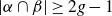
 $B (\cong [0,1] \times [0,1])$
, that is attached to
$B (\cong [0,1] \times [0,1])$
, that is attached to
 $\partial_1$
(SW) and
$\partial_1$
(SW) and
 $\partial_3$
(NE).
$\partial_3$
(NE).
Referring to the second illustration in the sequence in Figure 2, we take an arc,
 $\gamma$
, to be the extended core of the attached B. The salient feature is that
$\gamma$
, to be the extended core of the attached B. The salient feature is that
 $\gamma$
is attached to the south side (north side) of the west portion (east portion) of
$\gamma$
is attached to the south side (north side) of the west portion (east portion) of
 $\alpha \cap \nu$
. That is,
$\alpha \cap \nu$
. That is,
 $\partial \gamma$
is centered around the point p, or p is the center of
$\partial \gamma$
is centered around the point p, or p is the center of
 $\partial \gamma$
. Then
$\partial \gamma$
. Then
 $\alpha \cup \beta \cup \gamma$
will be a graph in
$\alpha \cup \beta \cup \gamma$
will be a graph in
 $\textbf{N} \cup B$
that has some number of 4-valent vertices—same number as
$\textbf{N} \cup B$
that has some number of 4-valent vertices—same number as
 $|\alpha \cap \beta|$
—and two 3-valent vertices—the two endpoints of
$|\alpha \cap \beta|$
—and two 3-valent vertices—the two endpoints of
 $ \gamma$
.
$ \gamma$
.
The third illustration in the sequence in Figure 2 shows a shearing of
 $\beta$
at the point p, creating two new 3-valent vertices. The reader should observe that we now have four 3-valent vertices in succession on
$\beta$
at the point p, creating two new 3-valent vertices. The reader should observe that we now have four 3-valent vertices in succession on
 $\alpha$
. The fourth illustration shows how these four 3-valent vertices are realigned and spliced to create two new 4-valent vertices and a new
$\alpha$
. The fourth illustration shows how these four 3-valent vertices are realigned and spliced to create two new 4-valent vertices and a new
 $\beta^\prime$
. The key feature of the final fourth illustration is that the orientation at the two intersections of
$\beta^\prime$
. The key feature of the final fourth illustration is that the orientation at the two intersections of
 $\alpha \cap \beta^\prime$
created by this splice is consistent with the original orientation intersection point,
$\alpha \cap \beta^\prime$
created by this splice is consistent with the original orientation intersection point,
 $\nu \cap (\alpha \cap \beta)$
—crossing
$\nu \cap (\alpha \cap \beta)$
—crossing
 $\alpha$
south to north.
$\alpha$
south to north.
We observe that if
 $\partial_1 \not= \partial_3$
then the
$\partial_1 \not= \partial_3$
then the
 $\partial(\textbf{N} \cup B)$
has one less boundary component and the genus of
$\partial(\textbf{N} \cup B)$
has one less boundary component and the genus of
 $\textbf{N} \cup B$
is increased by one. Moreover, the curve pair
$\textbf{N} \cup B$
is increased by one. Moreover, the curve pair
 $(\alpha, \beta^\prime)$
, will be a filling pair in the surface obtains by capping off each component of
$(\alpha, \beta^\prime)$
, will be a filling pair in the surface obtains by capping off each component of
 $\partial(\textbf{N} \cup B)$
with a disc, i.e.
$\partial(\textbf{N} \cup B)$
with a disc, i.e.
 $S_{g+1}$
. Additionally,
$S_{g+1}$
. Additionally,
 $|\alpha \cap \beta| +1 = |\alpha \cap \beta^\prime|$
.
$|\alpha \cap \beta| +1 = |\alpha \cap \beta^\prime|$
.
The surgery sequence obviously is generalised by rotation and reflection.
We will refer back to this shear and splice construction numerous times in this note.
The double 1-handle surgery—For this surgery we refer the reader to Figure 3 on how we will alter the initial
 $\nu(p)$
neighbourhood. Specifically, we glue in two 1-handles: a 1-handle,
$\nu(p)$
neighbourhood. Specifically, we glue in two 1-handles: a 1-handle,
 $B_{NW/SW}$
, that is attached to
$B_{NW/SW}$
, that is attached to
 $\partial_2$
(NW) and
$\partial_2$
(NW) and
 $\partial_1$
(SW); and, a 1-handle,
$\partial_1$
(SW); and, a 1-handle,
 $B_{SW/NE}$
attached to, again,
$B_{SW/NE}$
attached to, again,
 $\partial_1$
(SW) and
$\partial_1$
(SW) and
 $\partial_3$
(NE). Next, we take a core arc of each 1-handle and extend them into
$\partial_3$
(NE). Next, we take a core arc of each 1-handle and extend them into
 $\nu(p)$
so as to create a single arc,
$\nu(p)$
so as to create a single arc,
 $\gamma$
, that is attached to
$\gamma$
, that is attached to
 $\alpha$
on the north (south) side of the west (east) portion in
$\alpha$
on the north (south) side of the west (east) portion in
 $\nu(p)$
. Again,
$\nu(p)$
. Again,
 $\partial \gamma$
is centered around the point p, or p is the center of
$\partial \gamma$
is centered around the point p, or p is the center of
 $\partial \gamma$
. The thicker blue (online edition) or gray (print edition) arc in the left-hand illustration of Figure 3 corresponds to
$\partial \gamma$
. The thicker blue (online edition) or gray (print edition) arc in the left-hand illustration of Figure 3 corresponds to
 $\gamma$
. Note that at this stage
$\gamma$
. Note that at this stage
 $\alpha \cup \beta \cup \gamma$
is a graph in
$\alpha \cup \beta \cup \gamma$
is a graph in
 $\textbf{N} \cup B_{NW/SW} \cup B_{SW/NE}$
having
$\textbf{N} \cup B_{NW/SW} \cup B_{SW/NE}$
having
 $|\alpha \cap \beta| +1$
4-valent vertices and two 3-valent vertices.
$|\alpha \cap \beta| +1$
4-valent vertices and two 3-valent vertices.
The two 1-handle surgery. Banding three boundary components with one arc.

Finally, we shear
 $\beta$
at the point
$\beta$
at the point
 $p \in \alpha \cap \beta$
to create two 3-valent vertices. As with our first surgery, we will then have four 3-valent vertices in succession on
$p \in \alpha \cap \beta$
to create two 3-valent vertices. As with our first surgery, we will then have four 3-valent vertices in succession on
 $\alpha$
. The right illustration of Figure 3 shows the realignment of these four vertices creating two new 4-valent vertices and a new
$\alpha$
. The right illustration of Figure 3 shows the realignment of these four vertices creating two new 4-valent vertices and a new
 $\beta^\prime$
curve by splicing into
$\beta^\prime$
curve by splicing into
 $\beta$
the extended core arc. As with our first surgery, the two new vertices of
$\beta$
the extended core arc. As with our first surgery, the two new vertices of
 $\beta^\prime$
are intersections with
$\beta^\prime$
are intersections with
 $\alpha$
that are consistent with the manner of intersection of our original point p—crossing
$\alpha$
that are consistent with the manner of intersection of our original point p—crossing
 $\alpha$
south to north. Thus, again we have a shear and splice construction, going from
$\alpha$
south to north. Thus, again we have a shear and splice construction, going from
 $\beta$
to
$\beta$
to
 $\beta^\prime$
.
$\beta^\prime$
.
If we assume that
 $\partial_1, \partial_2, \partial_3$
are all distinct boundary curves of
$\partial_1, \partial_2, \partial_3$
are all distinct boundary curves of
 $\textbf{N}$
then
$\textbf{N}$
then
 $|\partial(\textbf{N} \cap B_{NW/SW} \cap B_{SW/NE})| = |\partial \textbf{N}| -2$
. Thus, the curve pair
$|\partial(\textbf{N} \cap B_{NW/SW} \cap B_{SW/NE})| = |\partial \textbf{N}| -2$
. Thus, the curve pair
 $(\alpha, \beta^\prime)$
, will be a filling pair in the surface obtained by capping off each component of
$(\alpha, \beta^\prime)$
, will be a filling pair in the surface obtained by capping off each component of
 $\partial(\textbf{N} \cap B_{NW/SW} \cap B_{SW/NE}))$
with a disc, i.e.
$\partial(\textbf{N} \cap B_{NW/SW} \cap B_{SW/NE}))$
with a disc, i.e.
 $S_{g+2}$
. Additionally,
$S_{g+2}$
. Additionally,
 $|\alpha \cap \beta| +2 = |\alpha \cap \beta^\prime|$
Finally, both the surgery sequences are generalised by rotation and reflection.
2·2. Constructing minimal coherent filling pairs.
With our two surgeries in hand we are now in a position to construct minimal coherent intersecting filling pairs for genus,
 $g \geq 3$
.
$g \geq 3$
.
As stated at the beginning of Section 2, we start with a filling pair on
 $S_1$
that intersects g-times. Again,
$S_1$
that intersects g-times. Again,
 $\alpha$
is a
$\alpha$
is a
 $\langle 0, 1 \rangle$
curve and
$\langle 0, 1 \rangle$
curve and
 $\beta$
as a
$\beta$
as a
 $\langle g,1 \rangle$
curve. We give an orientation to
$\langle g,1 \rangle$
curve. We give an orientation to
 $\alpha$
and label the g intersection points,
$\alpha$
and label the g intersection points,
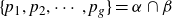 $\{p_1, p_2, \cdots , p_g\} = \alpha \cap \beta$
, such that the cyclic order of the points on
$\{p_1, p_2, \cdots , p_g\} = \alpha \cap \beta$
, such that the cyclic order of the points on
 $\alpha$
corresponds to the cyclic order given by indices of the
$\alpha$
corresponds to the cyclic order given by indices of the
 $\nu(p_i)$
-labels. Next we orient
$\nu(p_i)$
-labels. Next we orient
 $\beta$
similarly—traversing
$\beta$
similarly—traversing
 $\beta$
, mod(g) the
$\beta$
, mod(g) the
 $i{\rm th}$
intersection point is
$i{\rm th}$
intersection point is
 $p_i$
.
$p_i$
.
As depicted in Figure 4, it is convenient to represent the
 $\alpha$
curve by a horizontal line segment which has its left and right endpoints identified. Then we can represent the
$\alpha$
curve by a horizontal line segment which has its left and right endpoints identified. Then we can represent the
 $\beta$
curve by g vertical line segments, each one of which intersects our
$\beta$
curve by g vertical line segments, each one of which intersects our
 $\alpha$
representation once at its midpoint. Assigning labels—1 through g, left to right—to the top endpoints of our g vertical segments and labels, g then 1 through
$\alpha$
representation once at its midpoint. Assigning labels—1 through g, left to right—to the top endpoints of our g vertical segments and labels, g then 1 through
 $g-1$
, to the bottom ends of the vertical segments, we realise
$g-1$
, to the bottom ends of the vertical segments, we realise
 $\beta$
by a gluing that matches the top endpoint labels with the bottom endpoint labels.
$\beta$
by a gluing that matches the top endpoint labels with the bottom endpoint labels.
The first and third illustrations have
 $g = 3$
and
$g = 3$
and
 $g=5$
respectively and are representatives of the odd case. The second and fourth illustrations have
$g=5$
respectively and are representatives of the odd case. The second and fourth illustrations have
 $g=4$
and
$g=4$
and
 $g=6$
respectively and are representatives of the even case. The horizontal segments in each has the right/left endpoints identified and corresponds to the
$g=6$
respectively and are representatives of the even case. The horizontal segments in each has the right/left endpoints identified and corresponds to the
 $\alpha$
curve. The labels on the endpoints of the vertical segments correspond to the identification of their endpoints so as to form the
$\alpha$
curve. The labels on the endpoints of the vertical segments correspond to the identification of their endpoints so as to form the
 $\beta$
curve.
$\beta$
curve.

It is also helpful to assign labels,
 $p_1$
through
$p_1$
through
 $p_g$
, to the points of intersection of the horizontal
$p_g$
, to the points of intersection of the horizontal
 $\alpha$
segment with the vertical segments—
$\alpha$
segment with the vertical segments—
 $p_i$
will be in the vertical segment have i as a top endpoint label. Next, when we consider a regular neighbourhood,
$p_i$
will be in the vertical segment have i as a top endpoint label. Next, when we consider a regular neighbourhood,
 $\textbf{N}$
of
$\textbf{N}$
of
 $\alpha \cup \beta \subset S_1$
, near
$\alpha \cup \beta \subset S_1$
, near
 $p_i$
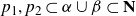
we have the four “compass” boundary curves,
$p_i$
we have the four “compass” boundary curves,
 $NE_i, NW_i , SW_i , SE_i$
, where, due to the indexing scheme for connecting the labels of the vertical segments,
$NE_i, NW_i , SW_i , SE_i$
, where, due to the indexing scheme for connecting the labels of the vertical segments,
 $NE_i = NW_{i+1}, SE_{i} = SW_{i+1}, NW_i = SE_i$
. To help the reader with this identification in Figure 4 we put numbers on vertical segments. The reader should observe that
$NE_i = NW_{i+1}, SE_{i} = SW_{i+1}, NW_i = SE_i$
. To help the reader with this identification in Figure 4 we put numbers on vertical segments. The reader should observe that
 $|\partial \textbf{N}| =g$
.
$|\partial \textbf{N}| =g$
.
Our construction requires that we consider the cases when g is odd and even separately. From top-to-bottom, the four illustrations in Figure 4 depict the cases:
 $g = 3$
(odd),
$g = 3$
(odd),
 $g=4$
(even),
$g=4$
(even),
 $g=5$
(odd), and
$g=5$
(odd), and
 $g=6$
(even). The observable pattern is that of
$g=6$
(even). The observable pattern is that of
 $(g-1)$
single 1-handle surgeries for the odd cases, and
$(g-1)$
single 1-handle surgeries for the odd cases, and
 $(g-2)$
single 1-handle surgeries and a single additional double 1-handle surgery for the even cases.
$(g-2)$
single 1-handle surgeries and a single additional double 1-handle surgery for the even cases.
The key issue is to determine when a “1-handle attaching scheme” to
 $\partial \textbf{N}$
results in a surface with one boundary. To that end we define an attaching graph or A-graph, G. The graph G is necessarily directed with labelled vertices. The vertices of G correspond to the components of
$\partial \textbf{N}$
results in a surface with one boundary. To that end we define an attaching graph or A-graph, G. The graph G is necessarily directed with labelled vertices. The vertices of G correspond to the components of
 $\partial \textbf{N}$
. For our specific construction, vertices will have have labels coming from the set,
$\partial \textbf{N}$
. For our specific construction, vertices will have have labels coming from the set,
 $\{ 1, \ldots , g \}$
—the vertex labelled i will be associated with the boundary component having
$\{ 1, \ldots , g \}$
—the vertex labelled i will be associated with the boundary component having
 $NW_i = SE_i$
. And, two vertices share an edge if they share the attaching ends of a specified 1-handle and the direction of the edge corresponds to the orientation of the 1-handle’s core arc. Thus, G will have g vertices and
$NW_i = SE_i$
. And, two vertices share an edge if they share the attaching ends of a specified 1-handle and the direction of the edge corresponds to the orientation of the 1-handle’s core arc. Thus, G will have g vertices and
 $g-1$
edges. We then have the following theorem.
$g-1$
edges. We then have the following theorem.
Theorem 2·1. Given an attaching scheme of
 $(g -1)$
1-handles to
$(g -1)$
1-handles to
 $\partial \textbf{N}$
, the resulting surface will have exactly one boundary component if and only if the associated A-graph, G, is a connected tree.
$\partial \textbf{N}$
, the resulting surface will have exactly one boundary component if and only if the associated A-graph, G, is a connected tree.
The proof of Theorem 2·1 will be delayed until Section 3.
We now give two schemes—one for g odd and one for g even—attaching 1-handles to
 $\textbf{N}$
, both utilise the 1-handle surgeries of Section 2.
$\textbf{N}$
, both utilise the 1-handle surgeries of Section 2.
Case where g is odd. In a neighbourhood of each intersection point,
 $p_i, \ 2 \leq i \leq g$
, we perform a single 1-handle surgery attached to
$p_i, \ 2 \leq i \leq g$
, we perform a single 1-handle surgery attached to
 ${SW}_i$
to
${SW}_i$
to
 ${NE}_i$
for
${NE}_i$
for
 $2 \leq i \leq g$
. It is readily observed that the graph, G, is a linear tree. (The reader may wish to consult the top of Figure 5.) Thus, by Theorem 2·1 the resulting surface has one boundary component and is of genus g.
$2 \leq i \leq g$
. It is readily observed that the graph, G, is a linear tree. (The reader may wish to consult the top of Figure 5.) Thus, by Theorem 2·1 the resulting surface has one boundary component and is of genus g.
The A-graphs corresponding to our handle scheme pattern illustrated in Figure 4. The upper is the odd case and the lower is the even case.

As previously observed, the resulting filling pair will still have coherent intersection.
Case where g is even. In a neighbourhood of
 $p_1$
we perform a double 1-handle surgery: attaching a 1-handle between
$p_1$
we perform a double 1-handle surgery: attaching a 1-handle between
 ${NW}_1$
and
${NW}_1$
and
 ${SW}_1$
; and,
${SW}_1$
; and,
 ${SW}_1$
and
${SW}_1$
and
 ${NE}_1$
. Then, in a neighbourhood of each intersection point,
${NE}_1$
. Then, in a neighbourhood of each intersection point,
 $p_i, \ 3 \leq i \leq g-2$
and
$p_i, \ 3 \leq i \leq g-2$
and
 $p_g$
, we perform a single 1-handle surgery attached to
$p_g$
, we perform a single 1-handle surgery attached to
 ${SW}_i$
to
${SW}_i$
to
 ${NE}_i$
for
${NE}_i$
for
 $3 \leq i \leq g-2$
and
$3 \leq i \leq g-2$
and
 $p_g$
. Again, it is readily observed that the associated graph, G, is a linear tree. (The reader may wish to consult the bottom of Figure 5.) And, Theorem 2·1 again gives us that the resulting surface has one boundary component and is of genus g.
$p_g$
. Again, it is readily observed that the associated graph, G, is a linear tree. (The reader may wish to consult the bottom of Figure 5.) And, Theorem 2·1 again gives us that the resulting surface has one boundary component and is of genus g.
And again, the resulting filling pair will still have coherent intersection.
Since our surgery schemes will produce the linear trees of Figure 5, Theorem 2·1 implies the following result.
Corollary 2·2. For genus
 $g\geq 3$
, we can create minimal coherent filling pairs utilising the two 1-handle surgeries of Section 2.
$g\geq 3$
, we can create minimal coherent filling pairs utilising the two 1-handle surgeries of Section 2.
By now the reader may have realised that there are other choices one may make for attaching 1-handles, shearing vertices and splicing in the extended handles cores so as to obtain a single boundary curve and a new
 $\beta^\prime$
. After we supply the proof of Theorem 2·1, we will investigate other such choices in Section 4.
$\beta^\prime$
. After we supply the proof of Theorem 2·1, we will investigate other such choices in Section 4.
Remark 2·3. For
 $g=2$
, if we attempt to attach a single 1-handle to
$g=2$
, if we attempt to attach a single 1-handle to
 $\partial \textbf{N}$
using the single 1-handle surgery we “run out of room”. That is, the associated graph, G, will not be a connected tree since both points,
$\partial \textbf{N}$
using the single 1-handle surgery we “run out of room”. That is, the associated graph, G, will not be a connected tree since both points,
 $p_1 , p_2 \subset \alpha \cup \beta \subset \textbf{N}$
, are adjacent to just the two boundary curves of
$p_1 , p_2 \subset \alpha \cup \beta \subset \textbf{N}$
, are adjacent to just the two boundary curves of
 $\partial \textbf{N}$
. Thus, we cannot realise a filling pair such that
$\partial \textbf{N}$
. Thus, we cannot realise a filling pair such that
 $|\alpha \cap \beta| = 2 \cdot g-1 = 2\cdot 2 - 1 =3$
. This “failure to construct” is consistent with the fact that for genus 2 we need
$|\alpha \cap \beta| = 2 \cdot g-1 = 2\cdot 2 - 1 =3$
. This “failure to construct” is consistent with the fact that for genus 2 we need
 $|\alpha \cap \beta| = 4$
.
$|\alpha \cap \beta| = 4$
.
3. Proof of Theorem 2·1
We now supply the proof of our previously used theorem.
Proof of Theorem 2·1. First, we will assume that the resulting surface has exactly one boundary component. We will argue that G must be a tree.
We observe that our definition of the graph G is really independent of the filling pair and only dependent on the surface type of
 $\textbf{N}$
. That is,
$\textbf{N}$
. That is,
 $\textbf{N}$
is homeomorphic to
$\textbf{N}$
is homeomorphic to
 $S_{1,0,g}$
. By attaching a 1-handle to any surface with boundary we either increase by one or decrease by one the number of boundary components of the resulting surface. To do the former (latter), both ends of the 1-handle must be attached to the same (different) boundary component(s).
$S_{1,0,g}$
. By attaching a 1-handle to any surface with boundary we either increase by one or decrease by one the number of boundary components of the resulting surface. To do the former (latter), both ends of the 1-handle must be attached to the same (different) boundary component(s).
With the above in mind, we take a
 $\hat{g}$
to be of minimal value for which the theorem is not true. Then for
$\hat{g}$
to be of minimal value for which the theorem is not true. Then for
 $\textbf{N} \cong S_{1,o,\hat{g}}$
, there is an attaching scheme of
$\textbf{N} \cong S_{1,o,\hat{g}}$
, there is an attaching scheme of
 $(\hat{g}-1)$
handle on the
$(\hat{g}-1)$
handle on the
 $\hat{g}$
boundary components that produces a single boundary curve, but the associated A-graph is not a tree.
$\hat{g}$
boundary components that produces a single boundary curve, but the associated A-graph is not a tree.
We next take a maximal sub-collection of handles that results in an A-graph,
 $G^\prime$
, with each component of
$G^\prime$
, with each component of
 $G^\prime$
being a tree. (By assumption this sub-collection has fewer than
$G^\prime$
being a tree. (By assumption this sub-collection has fewer than
 $(\hat{g} -1)$
handles.) The cardinality of our sub-collection of handles is
$(\hat{g} -1)$
handles.) The cardinality of our sub-collection of handles is
 $(\hat{g} - |G^\prime|)$
and, there are
$(\hat{g} - |G^\prime|)$
and, there are
 $|G^\prime| - 1$
remaining handles to attach. Moreover, each component accounts for one boundary component of the resulting sub-surface, i.e. there are
$|G^\prime| - 1$
remaining handles to attach. Moreover, each component accounts for one boundary component of the resulting sub-surface, i.e. there are
 $|G^\prime|$
boundary components.
$|G^\prime|$
boundary components.
If we now attach one of the handles not in our maximal sub-collection, it must result in a component of our A-graph not being a tree. This implies that both ends of this handle are attached to the same boundary component. But, this is not possible. We are in the situation where we have a surface with
 $|G^\prime| ( \lt \hat{g})$
boundary curves and
$|G^\prime| ( \lt \hat{g})$
boundary curves and
 $|G^\prime| -1 $
handles to be attached resulting in a single boundary component. By the assumption that
$|G^\prime| -1 $
handles to be attached resulting in a single boundary component. By the assumption that
 $\hat{g}$
is minimal for realising a counterexample, we have a contradiction.
$\hat{g}$
is minimal for realising a counterexample, we have a contradiction.
For the other direction of our theorem we proceeding inductively. If there are initially two components of
 $\partial \textbf{N}$
, attaching a 1-handle between them will produce a single boundary component and the associated G is a tree.
$\partial \textbf{N}$
, attaching a 1-handle between them will produce a single boundary component and the associated G is a tree.
Now consider the associated graph, G, coming from an attachment scheme of
 $(g-1)$
1-handles to the g boundary components of
$(g-1)$
1-handles to the g boundary components of
 $\textbf{N}$
. And, assume that G is a connected tree. We use
$\textbf{N}$
. And, assume that G is a connected tree. We use
 $\textbf{N}^\prime$
to denote the resulting surface and we observe that
$\textbf{N}^\prime$
to denote the resulting surface and we observe that
 $\textbf{N}$
is naturally seen as a sub-surface in
$\textbf{N}$
is naturally seen as a sub-surface in
 $\textbf{N}^\prime$
. Moreover, we can obtain
$\textbf{N}^\prime$
. Moreover, we can obtain
 $\textbf{N}$
from
$\textbf{N}$
from
 $\textbf{N}^\prime$
by deleting the open sets in
$\textbf{N}^\prime$
by deleting the open sets in
 $\textbf{N}^\prime$
that correspond to the “interior” of the 1-handles.
$\textbf{N}^\prime$
that correspond to the “interior” of the 1-handles.
We then have a similar behaviour to that described in the first half of our argument. By deleting the interior of a 1-handle to any surface with boundary we either increase or decrease by one the number of boundary components of the resulting surface. To do the former (latter), both components of
 $\{1 {\rm-handle}\} \cap \partial \textbf{N}^\prime$
must on the same (different) boundary component(s) of
$\{1 {\rm-handle}\} \cap \partial \textbf{N}^\prime$
must on the same (different) boundary component(s) of
 $\textbf{N}^\prime$
. Since the deletion of
$\textbf{N}^\prime$
. Since the deletion of
 $(g-1)$
interiors of 1-handles in
$(g-1)$
interiors of 1-handles in
 $\textbf{N}^\prime$
produces a surface with g boundary components, by G being connected—every boundary of
$\textbf{N}^\prime$
produces a surface with g boundary components, by G being connected—every boundary of
 $\textbf{N}$
has at least one 1-handle attached—we conclude that
$\textbf{N}$
has at least one 1-handle attached—we conclude that
 $|\partial \textbf{N}^\prime|=1$
.
$|\partial \textbf{N}^\prime|=1$
.
4. Alternative 1-handle schemes.
As previously observed, the associated A-graphs for the constructions in Section 2·2 will be the linear trees of Figure 5.
However, the 1-handle attaching scheme of Corollary 2·2 is not unique in that one can readily construct other 1-handle attaching schemes whose associated A-graph is a tree. We now offer a genus 6 example. The reader should refer to Figure 6.
The arc,
 $\gamma$
, contains the extended core of five 1-handles. There is only one shear and splice which is at
$\gamma$
, contains the extended core of five 1-handles. There is only one shear and splice which is at
 $p_2$
. It splices
$p_2$
. It splices
 $\gamma$
into
$\gamma$
into
 $\beta$
to produce
$\beta$
to produce
 $\beta^\prime$
. The lower illustration depicts the associated A-graph, G, which is a tree.
$\beta^\prime$
. The lower illustration depicts the associated A-graph, G, which is a tree.

Example 4·1. [An attaching scheme for
 $S_{6}$
] Initially, the
$S_{6}$
] Initially, the
 $\beta$
curve is the (6, 1) curve on
$\beta$
curve is the (6, 1) curve on
 $S_1$
with
$S_1$
with
 $\alpha$
again being the (0, 1) curve. As before, we will have
$\alpha$
again being the (0, 1) curve. As before, we will have
 $\{p_1, \cdots, p_6 \} = \alpha \cap \beta$
which we indicate in the top illustration of Figure 6. To reduce the clutter we do not depict the vertical arcs associated with
$\{p_1, \cdots, p_6 \} = \alpha \cap \beta$
which we indicate in the top illustration of Figure 6. To reduce the clutter we do not depict the vertical arcs associated with
 $\beta$
. Finally, we label the boundary components of
$\beta$
. Finally, we label the boundary components of
 $\partial \textbf{N}$
with numeric labels.
$\partial \textbf{N}$
with numeric labels.
We depict an oriented thick blue (online edition) or gray (print edition) arc,
 $\gamma$
, that has endpoints in
$\gamma$
, that has endpoints in
 $\alpha$
to the left and right of the point,
$\alpha$
to the left and right of the point,
 $p_2( \in \alpha \cap \beta)$
. We will use
$p_2( \in \alpha \cap \beta)$
. We will use
 $\gamma$
for a scheme of attaching five 1-handles to the components of
$\gamma$
for a scheme of attaching five 1-handles to the components of
 $\partial \textbf{N}$
. Specifically,
$\partial \textbf{N}$
. Specifically,
 $\gamma$
is the union of five extended 1-handled cores. These five extended cores have their endpoints in
$\gamma$
is the union of five extended 1-handled cores. These five extended cores have their endpoints in
 $\alpha$
: one to the right of
$\alpha$
: one to the right of
 $p_1$
; one to the right of
$p_1$
; one to the right of
 $p_3$
; one to the left of
$p_3$
; one to the left of
 $p_6$
; and, the two endpoints that are to the left and right of
$p_6$
; and, the two endpoints that are to the left and right of
 $p_2$
.
$p_2$
.
The last two listed points, the endpoints of
 $\gamma$
are of particular interest. They are positioned on
$\gamma$
are of particular interest. They are positioned on
 $\alpha$
so that we can splice
$\alpha$
so that we can splice
 $\gamma$
into
$\gamma$
into
 $\beta$
by a shearing of
$\beta$
by a shearing of
 $\beta$
at
$\beta$
at
 $p_2$
followed by a reconnecting of endpoints as previously depicted in Figure 2 & Figure 3—they are “centered around”
$p_2$
followed by a reconnecting of endpoints as previously depicted in Figure 2 & Figure 3—they are “centered around”
 $p_2$
. The resulting curve will be our new
$p_2$
. The resulting curve will be our new
 $\beta^\prime$
. Returning to the orientation assignment of
$\beta^\prime$
. Returning to the orientation assignment of
 $\gamma$
, it is consistent with the orientation of
$\gamma$
, it is consistent with the orientation of
 $\beta$
that we have been assigning—edges of
$\beta$
that we have been assigning—edges of
 $\beta$
are depicted as coming into
$\beta$
are depicted as coming into
 $\alpha$
from below and going out of
$\alpha$
from below and going out of
 $\alpha$
from above. Thus, the new
$\alpha$
from above. Thus, the new
 $\beta^\prime$
will have coherent intersection with
$\beta^\prime$
will have coherent intersection with
 $\alpha$
.
$\alpha$
.
The bottom illustration of Figure 6 depicts the associated A-graph, G. (The validity of G we leave it to the reader to check.) Since G is a tree by our Theorem 2·1 we conclude that this scheme for attaching 1-handles yields a minimal coherent filling pair for
 $S_{6}$
. Moreover, the extended cores of the 1-handles inherit an orientation from
$S_{6}$
. Moreover, the extended cores of the 1-handles inherit an orientation from
 $\gamma$
that results in giving each edge of G an orientation, e.g. the core of the 1-handle goes from boundary curve 1 to boundary curve 6 giving us a edge in G going from Vertex 1 to Vertex 6.
$\gamma$
that results in giving each edge of G an orientation, e.g. the core of the 1-handle goes from boundary curve 1 to boundary curve 6 giving us a edge in G going from Vertex 1 to Vertex 6.
From this example we see that an attaching scheme for a collection of 1-handles can be described by specifying a disjoint collection of oriented arcs,
 $\{\gamma_1, \cdots , \gamma_n\}$
, that have their endpoints on our initial
$\{\gamma_1, \cdots , \gamma_n\}$
, that have their endpoints on our initial
 $\alpha$
curve—a
$\alpha$
curve—a
 $ \langle 0,1 \rangle$
curve on
$ \langle 0,1 \rangle$
curve on
 $S_1$
—and intersect
$S_1$
—and intersect
 $\alpha$
is a coherent manner that is consistent with that of
$\alpha$
is a coherent manner that is consistent with that of
 $\beta$
—a
$\beta$
—a
 $\langle g,1 \rangle$
curve on
$\langle g,1 \rangle$
curve on
 $S_1$
. Then, 1-handles are attached to
$S_1$
. Then, 1-handles are attached to
 $\textbf{N}$
so as to have their extended cores equal
$\textbf{N}$
so as to have their extended cores equal
 $\cup_{1 \leq i \leq n} \gamma_i$
. Each
$\cup_{1 \leq i \leq n} \gamma_i$
. Each
 $\gamma_i$
satisfies the following (
$\gamma_i$
satisfies the following (
 $\star$
) conditions:
$\star$
) conditions:
-
(1) for
$\partial \gamma_i$
there exists an intersection point
$p \in \alpha \cap \beta$
such that on
$\alpha$
these two endpoints are to the immediate left/right of p. That is,
$\partial \gamma_i$
is centered around of p; -
(2)
$\gamma_i$
intersects
$\alpha$
in a coherent manner; -
(3)
$\gamma_i$
is attached to
$\alpha$
and oriented such that a shear and splice operation at the point p (previous condition) yields a consistently oriented curve coherently intersecting
$\alpha$
.


A collection of
 $\gamma$
arcs satisfying the above three conditions are said to be a 1-handle attaching scheme.
$\gamma$
arcs satisfying the above three conditions are said to be a 1-handle attaching scheme.
Performing the shear and splice operation for each
 $\gamma$
arc of a 1-handle attaching scheme will yield a curve pair,
$\gamma$
arc of a 1-handle attaching scheme will yield a curve pair,
 $(\alpha, \beta^\prime)$
, for some oriented some closed surface. Additionally, a corresponding A-graph, G, can be constructed.
$(\alpha, \beta^\prime)$
, for some oriented some closed surface. Additionally, a corresponding A-graph, G, can be constructed.
We have the following theorem whose proof is now self-evident.
Theorem 4·2. Let
 $\{\gamma_1, \cdots , \gamma_n\}$
be a 1-handle attaching scheme. Suppose
$\{\gamma_1, \cdots , \gamma_n\}$
be a 1-handle attaching scheme. Suppose
 \begin{align*}|\cup^n_1 \gamma_i \cap \alpha| -n = g-1 . \end{align*}
Then the resulting curve pair is a minimal coherent filling pair for a
 $S_g$
if and only if the A-graph, G, is a connected tree.
$S_g$
if and only if the A-graph, G, is a connected tree.
5. A-graphs and H-graphs
Theorem 4·2 gives us a weak correspondence between 1-handle attaching schemes that yield minimal coherent filling pairs on
 $S_g$
and graphs that are directed trees with g labelled vertices. The classical result of Cayley’s formula [
Reference Cayley4
] tells us that there are
$S_g$
and graphs that are directed trees with g labelled vertices. The classical result of Cayley’s formula [
Reference Cayley4
] tells us that there are
 ${g}^{g-2}$
distinct labelled trees having g vertices. Since we only care about the labels up to a cyclic permutation, the exponent can be reduced by one. When accounting for possible orientations of edge, we have the enhanced count of
${g}^{g-2}$
distinct labelled trees having g vertices. Since we only care about the labels up to a cyclic permutation, the exponent can be reduced by one. When accounting for possible orientations of edge, we have the enhanced count of
 $2^{g-1} {g}^{g-3}$
candidates for A-graphs for genus g. Although getting a reasonable estimate on how many of these graphs correspond to an A-graph is beyond the scope of this paper, we now offer a necessary and sufficient condition for such a directed labelled tree being a realisable A-graph. This is accomplished by introducing “handle graphs”.
$2^{g-1} {g}^{g-3}$
candidates for A-graphs for genus g. Although getting a reasonable estimate on how many of these graphs correspond to an A-graph is beyond the scope of this paper, we now offer a necessary and sufficient condition for such a directed labelled tree being a realisable A-graph. This is accomplished by introducing “handle graphs”.
5·1. Handle graphs.
Let
 $\gamma \in \{ \gamma_1 , \cdots , \gamma_n \}$
be an arc of a 1-handle attaching scheme coming from Theorem 4·2. The handle-graph, or H-graph associated with
$\gamma \in \{ \gamma_1 , \cdots , \gamma_n \}$
be an arc of a 1-handle attaching scheme coming from Theorem 4·2. The handle-graph, or H-graph associated with
 $\gamma$
,
$\gamma$
,
 $H(\gamma)$
, is a directed linear tree satisfying the following
$H(\gamma)$
, is a directed linear tree satisfying the following
 $(\!\star \star)$
conditions:
$(\!\star \star)$
conditions:
-
(V) the vertices of
$H(\gamma)$
correspond to the points of
$\gamma \cap \partial \textbf{N}$
, where
$\textbf{N} \subset S_1$
is, again, the regular neighbourhood of
$\alpha \cup \beta$
. As with the A-graph, each vertex has a label from
$\{ 1 , \cdots , g \}$
, the label of the associated boundary curve of
$\textbf{N}$
, and different vertices may (and likely will) share the same label; -
(E) the directed edges of
$H(\gamma)$
are of two types:


-
(i) Exterior. Edges that correspond to the core of a 1-handle that is attached between two components of
$\partial \textbf{N}$
—thus, exterior edges also correspond to edges in the A-graph. The direction of these edges is inherited from the orientation of
$\gamma$
. -
(ii) Interior. Edges that correspond to proper arcs in
$\textbf{N}$
. Thus, such edges are between the two points/vertices of
$\gamma \cap \partial \textbf{N}$
above and below a point of
$int(\gamma) \cap \alpha$
. The direction of these edges is inherited from the orientation of
$\gamma$
. Observe that the vertex labels of such edges differ by
$+1 \ mod(g)$
. To emphasise this, we label such edges by a
$+1$
. -
(Centers and ends) Since each
$\gamma_i, 1 \leq i \leq n$
, has a center,
$p_j \in \alpha \cap \beta$
, we have the following sub-conditions: -
Ends. The labels of the end vertices of
$H(\gamma)$
are either the same or differ by
$2 \ mod(g)$
; -
Centers. Each point,
$p_i \in \alpha \cap \beta, \ 1 \leq i \leq g$
, is the center of at most one
$\gamma_i, 1 \leq i \leq n$
.


Remark 5·1. Concerning the centers and ends sub-conditions, observe that if the end labels are the same then the H-graph will necessarily have at least one interior edge. Additionally, the orientations of the edges are consistently oriented so as to give the vertices a linear ordering.
5·2. Some interesting examples.
The example coming from the single
 $\gamma$
arc of Figure 6 and Example 4·1 should serve to illustrate an H-graph.
$\gamma$
arc of Figure 6 and Example 4·1 should serve to illustrate an H-graph.
![]()
Example 5·2. (H-graph for Example 4·1 attaching scheme.) Above we depicted the H-graph of the single arc,
 $\gamma$
, of the 1-handle scheme of Example 4·1 as illustrated in Figure 6. We rely on the reader to verify
$\gamma$
, of the 1-handle scheme of Example 4·1 as illustrated in Figure 6. We rely on the reader to verify
 $H(\gamma)$
corresponds to Example 4·1—with a little help. First, one should observe that the vertex set of
$H(\gamma)$
corresponds to Example 4·1—with a little help. First, one should observe that the vertex set of
 $H(\gamma)$
maps onto the vertex set of A-graph in Figure 6. The onto multiplicity count corresponds to the valence of each vertex in the A-graph—there are three vertices having the label “1” in
$H(\gamma)$
maps onto the vertex set of A-graph in Figure 6. The onto multiplicity count corresponds to the valence of each vertex in the A-graph—there are three vertices having the label “1” in
 $H(\gamma)$
and the “1” vertex of the A-graph in Figure 6 is adjacent to three edges.
$H(\gamma)$
and the “1” vertex of the A-graph in Figure 6 is adjacent to three edges.
Next, observe that there is a one-to-one correspondence between the exterior edges—edges without the
 $+1$
over-label—of
$+1$
over-label—of
 $H(\gamma)$
and the edges of the A-graph of Figure 5. As depicted above, all exterior edges have their direction consistence with those of the A-graph.
$H(\gamma)$
and the edges of the A-graph of Figure 5. As depicted above, all exterior edges have their direction consistence with those of the A-graph.
The interior edges all have an
 $+1$
over-label—the change in value of the adjacent vertices mod(6).
$+1$
over-label—the change in value of the adjacent vertices mod(6).
Finally, observe that the labels of the end vertices are equal—in this case they are both 1. This is due to condition (1) of (
 $\star$
) which is aligned with the Centers and ends conditions of (
$\star$
) which is aligned with the Centers and ends conditions of (
 $\star \star$
).
$\star \star$
).
A 1-handle attaching scheme,
 $\{\gamma_1, \ldots , \gamma_n\}$
, will yield the set of H-graphs,
$\{\gamma_1, \ldots , \gamma_n\}$
, will yield the set of H-graphs,
 $\{H(\gamma_1), \ldots , H(\gamma_n)\}$
. By construction, there is a one-to-one map from the exterior edges of the
$\{H(\gamma_1), \ldots , H(\gamma_n)\}$
. By construction, there is a one-to-one map from the exterior edges of the
 $H(\gamma_i){\rm 's}$
to the edges of the associated A-graph. However, an A-graph may be associated with more than one attaching scheme. For Example 4·1, we can readily produce an alternative attaching scheme that yields the same A-graph by interchange the order of the two points of intersection of
$H(\gamma_i){\rm 's}$
to the edges of the associated A-graph. However, an A-graph may be associated with more than one attaching scheme. For Example 4·1, we can readily produce an alternative attaching scheme that yields the same A-graph by interchange the order of the two points of intersection of
 $\gamma$
with the segment of
$\gamma$
with the segment of
 $\alpha$
between
$\alpha$
between
 $p_3$
and
$p_3$
and
 $p_4$
. (See Figure 6.) This pathology is present even for the simplest graph—linear—as the following example of genus 5 illustrates.
$p_4$
. (See Figure 6.) This pathology is present even for the simplest graph—linear—as the following example of genus 5 illustrates.
Example 5·3. (Two attaching schemes for
 $S_{5}$
having the same A-graph.) Referring back to Figure 4, the
$S_{5}$
having the same A-graph.) Referring back to Figure 4, the
 $g=5$
depicted case has attaching schemes with 5
$g=5$
depicted case has attaching schemes with 5
 $\gamma$
-arcs. Thus, the associated five H-graphs are exactly a single exterior edge—no interior edges. The associated A-graph is a linear tree in the family of the top graph of Figure 5. However, we can alter this attaching scheme so that there is exactly one H-graph: align the pairs endpoints of the
$\gamma$
-arcs. Thus, the associated five H-graphs are exactly a single exterior edge—no interior edges. The associated A-graph is a linear tree in the family of the top graph of Figure 5. However, we can alter this attaching scheme so that there is exactly one H-graph: align the pairs endpoints of the
 $\gamma$
-arcs between
$\gamma$
-arcs between
 $p_2$
and
$p_2$
and
 $p_3$
,
$p_3$
,
 $p_3$
and
$p_3$
and
 $p_4$
, and
$p_4$
, and
 $p_4$
and
$p_4$
and
 $p_5$
. This aligning corresponds to adjoining two H-graphs by adding an interior edge. The resultant attaching scheme is one single 1-handle attaching scheme satisfying the conditions of (
$p_5$
. This aligning corresponds to adjoining two H-graphs by adding an interior edge. The resultant attaching scheme is one single 1-handle attaching scheme satisfying the conditions of (
 $\star$
). The associated H-graph will satisfy the (
$\star$
). The associated H-graph will satisfy the (
 $\star \star$
) conditions and will have three interior edges. Specifically, this single H-graph will satisfy the, “same or differ by
$\star \star$
) conditions and will have three interior edges. Specifically, this single H-graph will satisfy the, “same or differ by
 $2 \ mod(g)$
,” observation of Remark 5·1. But, the associated A-graph remains unchanged.
$2 \ mod(g)$
,” observation of Remark 5·1. But, the associated A-graph remains unchanged.
The pathology of having multiple attaching schemes associated with the same A-graph is further complicated by the possibility that the underlying origamis are in fact the same. Our next example illustrates this possibility.
Example 5·4. (Two different attaching schemes for
 $S_{3}$
.)
$S_{3}$
.)
A similar alteration can be done for the
 $g=3$
case so as to have two different attaching schemes. Specifically, referring back to Figure 4, the
$g=3$
case so as to have two different attaching schemes. Specifically, referring back to Figure 4, the
 $g=3$
depicted case has attaching schemes with 2
$g=3$
depicted case has attaching schemes with 2
 $\gamma$
-arcs, and the associated two H-graphs each have a single exterior edge. The associated A-graph comes from a linear tree family of the top graph of Figure 5.
$\gamma$
-arcs, and the associated two H-graphs each have a single exterior edge. The associated A-graph comes from a linear tree family of the top graph of Figure 5.
To produce a different attaching scheme we can alter this attaching scheme so as to align the pairs endpoints of the
 $\gamma$
-arcs between
$\gamma$
-arcs between
 $p_2$
and
$p_2$
and
 $p_3$
. This attaching scheme will have exactly one H-graph—the “adjoining” the two previous H-graphs together with a single interior edge.
$p_3$
. This attaching scheme will have exactly one H-graph—the “adjoining” the two previous H-graphs together with a single interior edge.
As previously mentioned, Figure 1 depicts the unique [1, 1]-origami up to labelling for
 $g=3$
[
Reference Aougab, Menasco and Nieland2, Reference Chang5
]. Thus, our two attaching schemes yield equivalent minimally intersecting coherent filling pairs.
$g=3$
[
Reference Aougab, Menasco and Nieland2, Reference Chang5
]. Thus, our two attaching schemes yield equivalent minimally intersecting coherent filling pairs.
Remark 5·5. We are considering
 $SL^{\pm}(2,\mathbb{Z})$
-orbits of origamis here, allowing for orientation reversing homeomorphisms. This notion of equivalent origamis is consistent with Section 5 and [
Reference Aougab, Menasco and Nieland2
, theorem 1·3]. The more restrictive equivalency relationship of orientation preserving homeomorphisms associated with
$SL^{\pm}(2,\mathbb{Z})$
-orbits of origamis here, allowing for orientation reversing homeomorphisms. This notion of equivalent origamis is consistent with Section 5 and [
Reference Aougab, Menasco and Nieland2
, theorem 1·3]. The more restrictive equivalency relationship of orientation preserving homeomorphisms associated with
 $SL(2,\mathbb{Z})$
-orbits results in there being two [1, 1]-origamis instead of one for genus 3.
$SL(2,\mathbb{Z})$
-orbits results in there being two [1, 1]-origamis instead of one for genus 3.
These examples illustrate the difficulty in producing a lower bound for the count of distinct minimal coherent filling pairs of genus g based just upon the information obtained from the A-graph. For genus four, our enhanced Cayley–formula would say that there are 128 distinct candidates for A-graphs. One could further reduce this count by considering more symmetries of the graphs. But as we have seen, there may be more than one attaching scheme associated with a single A-graph and duplications may be present in such a count—the pathologies imply both under-counting and over-counting. (Moreover, by Example 6·3 in Section 6·1, some origamis cannot be obtained through an attaching scheme.) Clearly, more analysis is needed—a direction for further investigation—for understanding how the combinatorics for attaching schemes might be employed in calculating the growth rate of minimal coherent filling pairs with respect to genus.
5·3. A theorem on A- & H-graphs
We now explore the relationship between A-graphs and H-graphs. Let G be a directed tree graph with g labelled vertices using all the labels coming from the set,
 $\{1, \ldots g \}$
. Let
$\{1, \ldots g \}$
. Let
 $\mathcal{G}= \{ G_1 , \ldots , G_g \}$
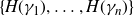
be all of the subgraphs of G that have exactly one directed edge and two labelled vertices. We will use the notation,
$\mathcal{G}= \{ G_1 , \ldots , G_g \}$
be all of the subgraphs of G that have exactly one directed edge and two labelled vertices. We will use the notation,
 $\sharp(v)$
, as the value of the label of vertex v.
$\sharp(v)$
, as the value of the label of vertex v.
For an element,
 $G_i \in \mathcal{G}$
, due to its edge,
$G_i \in \mathcal{G}$
, due to its edge,
 $e^{\rm {\tiny E}}_i (\!\subset G_i)$
, being directed we can naturally assign a sign to each vertex,
$e^{\rm {\tiny E}}_i (\!\subset G_i)$
, being directed we can naturally assign a sign to each vertex,
 $v^-_i , v^+_i \in \partial G_i$
(
$v^-_i , v^+_i \in \partial G_i$
(
 $\partial G_i$
means the leaves of
$\partial G_i$
means the leaves of
 $G_i$
, and in this case, the only two vertices of
$G_i$
, and in this case, the only two vertices of
 $G_i$
)—we start
$G_i$
)—we start
 $e^{\rm {\tiny E}}_i$
at
$e^{\rm {\tiny E}}_i$
at
 $v^-_i$
and end it at
$v^-_i$
and end it at
 $v^+_i$
. Given distinct subgraphs,
$v^+_i$
. Given distinct subgraphs,
 $G_i , G_j \in \mathcal{G}$
, we can consistently adjoin them together by inserting a directed edge,
$G_i , G_j \in \mathcal{G}$
, we can consistently adjoin them together by inserting a directed edge,
 $e^{\rm {\tiny I}}_{ij}$
, with
$e^{\rm {\tiny I}}_{ij}$
, with
 $v^+_i \cup v^-_j = \partial e^{\rm {\tiny I}}_{ij}$
exactly when
$v^+_i \cup v^-_j = \partial e^{\rm {\tiny I}}_{ij}$
exactly when
 $\sharp(v^-_j) - \sharp(v^+_i) = 1 \ mod(g)$
. The resulting graph,
$\sharp(v^-_j) - \sharp(v^+_i) = 1 \ mod(g)$
. The resulting graph,
 \begin{align*}G_i \cap e^{\rm {\tiny I}}_{ij} \cap G_j,\end{align*}
will be an oriented linear tree with three edges and four vertices. (The superscripts, “ E” and “ I”, are meant to be helpful references to, “exterior” and “interior”, respectively.) The operation of “consistently adjoining” can be iterated with other subgraphs of
 $\mathcal{G}$
. The only condition being imposed is that on the boundary labels,
$\mathcal{G}$
. The only condition being imposed is that on the boundary labels,
 $\sharp(v^-_j) - \sharp(v^+_i) = 1 \ mod(g)$
.
$\sharp(v^-_j) - \sharp(v^+_i) = 1 \ mod(g)$
.
Let
 $\mathcal{H}= \{H_1 , \ldots , H_n \}$
be a collection of oriented linear trees obtained from some sequence of consistently adjoining subgraphs of
$\mathcal{H}= \{H_1 , \ldots , H_n \}$
be a collection of oriented linear trees obtained from some sequence of consistently adjoining subgraphs of
 $\mathcal{G}$
together. (Notice that we are allowing for some linear trees being just
$\mathcal{G}$
together. (Notice that we are allowing for some linear trees being just
 $G_i{\rm 's}$
.) We say
$G_i{\rm 's}$
.) We say
 $H_k (\!\in \mathcal{H})$
ends well if for,
$H_k (\!\in \mathcal{H})$
ends well if for,
 $\partial H_K = v^+_k \cup v^-_k$
, we have
$\partial H_K = v^+_k \cup v^-_k$
, we have
 $\sharp(v^+_k) - \sharp(v^-_k) = 0, \ {\rm or} \ 2 \ mod(g)$
. When
$\sharp(v^+_k) - \sharp(v^-_k) = 0, \ {\rm or} \ 2 \ mod(g)$
. When
 $\sharp(v^-_k) - \sharp(v^+_k) = 0$
we say
$\sharp(v^-_k) - \sharp(v^+_k) = 0$
we say
 $H_k$
has center
$H_k$
has center
 $\sharp(v^-_k)$
. When
$\sharp(v^-_k)$
. When
 $\sharp(v^-_k) - \sharp(v^+_k) = 2 \ mod(g)$
, we say
$\sharp(v^-_k) - \sharp(v^+_k) = 2 \ mod(g)$
, we say
 $H_k$
has center
$H_k$
has center
 $\sharp(v^+_k) + 1$
.
$\sharp(v^+_k) + 1$
.
Finally, we say
 $\mathcal{H}$
ends well if each of its trees ends well. And, we say
$\mathcal{H}$
ends well if each of its trees ends well. And, we say
 $\mathcal{H}$
is well centered if the center of all its trees are distinct.
$\mathcal{H}$
is well centered if the center of all its trees are distinct.
Theorem 5·6. Let G be a directed tree graph with g labelled vertices as described above. Additionally, let
 $\mathcal{G}$
be
$\mathcal{G}$
be
 $G {\rm 's}$
subgraph set as described above. G is equal to an A-graph for some attaching scheme if and only if there exists a collection,
$G {\rm 's}$
subgraph set as described above. G is equal to an A-graph for some attaching scheme if and only if there exists a collection,
 $\mathcal{H}$
—oriented linear trees with labelled vertices—obtained from
$\mathcal{H}$
—oriented linear trees with labelled vertices—obtained from
 $\mathcal{G}$
through consistent adjoining such that
$\mathcal{G}$
through consistent adjoining such that
 $\mathcal{H}$
ends well and is well centered.
$\mathcal{H}$
ends well and is well centered.
Proof. Assume we have an A-graph, G. Let
 $\Gamma = \{\gamma_1 , \cdots , \gamma_n\}$
, be the associated 1-handle attaching scheme. We observe that there is a one-to-one correspondence between the collection of exterior edges of
$\Gamma = \{\gamma_1 , \cdots , \gamma_n\}$
, be the associated 1-handle attaching scheme. We observe that there is a one-to-one correspondence between the collection of exterior edges of
 $\Gamma$
and the subgraphs in
$\Gamma$
and the subgraphs in
 $\mathcal{G}$
. Then the needed collection of oriented linear trees,
$\mathcal{G}$
. Then the needed collection of oriented linear trees,
 $\mathcal{H}$
, is obtained by making the correspondence between each interior edge of
$\mathcal{H}$
, is obtained by making the correspondence between each interior edge of
 $\Gamma$
and the
$\Gamma$
and the
 $e^{\rm{\tiny I}}_{ij}$
edges used for consistently adjoining subgraphs of
$e^{\rm{\tiny I}}_{ij}$
edges used for consistently adjoining subgraphs of
 $\mathcal{G}$
together. The adjoining-condition,
$\mathcal{G}$
together. The adjoining-condition,
 $\sharp(v^-_j) - \sharp(v^+_i) = 1 \ mod(g)$
, is satisfied due to
$\sharp(v^-_j) - \sharp(v^+_i) = 1 \ mod(g)$
, is satisfied due to
 $+1 \ mod(g)$
condition of (
$+1 \ mod(g)$
condition of (
 $\star \star$
) on interior edges. Each oriented linear tree ends well due to the Ends condition of (
$\star \star$
) on interior edges. Each oriented linear tree ends well due to the Ends condition of (
 $\star \star$
). Similarly, each tree is well centered at distinct unique point by the Centers condition of (
$\star \star$
). Similarly, each tree is well centered at distinct unique point by the Centers condition of (
 $\star \star$
).
$\star \star$
).
Arguing the other direction is just observing the above correspondence between: “
 $\mathcal{H}$
ends well” and the Ends condition of (
$\mathcal{H}$
ends well” and the Ends condition of (
 $\star \star$
); and, “
$\star \star$
); and, “
 $\mathcal{H}$
is well centered” and the Center condition of (
$\mathcal{H}$
is well centered” and the Center condition of (
 $\star \star$
). Additionally, the edges of
$\star \star$
). Additionally, the edges of
 $\mathcal{G}$
correspond to the exterior edges of condition (
$\mathcal{G}$
correspond to the exterior edges of condition (
 $\star \star$
) and the interior edges of condition (
$\star \star$
) and the interior edges of condition (
 $\star \star$
) correspond to the edges used to adjoin subgraphs.
$\star \star$
) correspond to the edges used to adjoin subgraphs.
6. Alternative methods of construction.
As referenced previously, alternative methods of constructing minimally intersecting coherent filling pairs of closed curves in
 $S_g$
are given by Aougab-Menasco-Neiland in [
Reference Aougab, Menasco and Nieland2
] and Jeffreys in [
Reference Jeffreys9
]. In this section we investigate how much, if any, overlap there is between the filling pairs of these methods and the filling pairs produced by the construction methods in Section 2·2.
$S_g$
are given by Aougab-Menasco-Neiland in [
Reference Aougab, Menasco and Nieland2
] and Jeffreys in [
Reference Jeffreys9
]. In this section we investigate how much, if any, overlap there is between the filling pairs of these methods and the filling pairs produced by the construction methods in Section 2·2.
It is a common feature for all these methods of construction that there is a bifurcation into an odd genus construction and an even genus construction. In [
Reference Aougab, Menasco and Nieland2
], permutation equations are developed, that when satisfied, determine if a
 $\tau_{\alpha,\beta}$
-permutation is realised by a minimal coherent filling pair. The constructions in [
Reference Jeffreys9
] are more akin to the construction given in Section 2. Jeffreys defines combinatorial moves that we shall call “finger moves” on filling pairs in
$\tau_{\alpha,\beta}$
-permutation is realised by a minimal coherent filling pair. The constructions in [
Reference Jeffreys9
] are more akin to the construction given in Section 2. Jeffreys defines combinatorial moves that we shall call “finger moves” on filling pairs in
 $S_1$
that yield higher genus minimal coherent filling pairs. Moreover, the resultant curves are presented in both a ladder graph format and a corresponding
$S_1$
that yield higher genus minimal coherent filling pairs. Moreover, the resultant curves are presented in both a ladder graph format and a corresponding
 $(2, 2g-1)$
-array diagram.
$(2, 2g-1)$
-array diagram.
6·1. The Aougab-Menasco-Neiland construction from [ Reference Aougab, Menasco and Nieland2 ]
As first depicted in the left illustration of Figure 1, our presentations of filling pairs on a surface have been “ladder graphs”. (So see Figure 4.) The salient information of such ladder graphs is the top and bottom numeric labels associated with the
 $\beta$
curve segments. This label information can be captured by the
$\beta$
curve segments. This label information can be captured by the
 $(2,2g-1)$
-array diagrams introduced in [
Reference Aougab, Menasco and Nieland2
]. For the left ladder graph of Figure 1 the diagram is:
$(2,2g-1)$
-array diagrams introduced in [
Reference Aougab, Menasco and Nieland2
]. For the left ladder graph of Figure 1 the diagram is:
 \begin{align*}\begin{array}{c c c c c}1 & 3 & 2 & 5 & 4\\[5pt] 5 & 2 & 1 & 4 & 3\end{array}.\end{align*}
The curve
 $\alpha$
comes from identifying the left/right ends of the horizontal “spine” of a ladder graph.
$\alpha$
comes from identifying the left/right ends of the horizontal “spine” of a ladder graph.
Remark 6·1. Although the use of
 $(2,2g-1)$
-array permutation diagrams is common to both the work of Aougab-Menasco-Neiland and Jeffreys, it is not quite standardized. In [
Reference Jeffreys9
], the vertical mid-segments are oriented downward instead of upward. We adopt a standard from [
Reference Aougab, Menasco and Nieland2
] where the vertical mid-segments are oriented upward.
$(2,2g-1)$
-array permutation diagrams is common to both the work of Aougab-Menasco-Neiland and Jeffreys, it is not quite standardized. In [
Reference Jeffreys9
], the vertical mid-segments are oriented downward instead of upward. We adopt a standard from [
Reference Aougab, Menasco and Nieland2
] where the vertical mid-segments are oriented upward.
With an order cyclic labelling of the intersection points of
 $\alpha \cap \beta$
, a
$\alpha \cap \beta$
, a
 $(2,2g-1)$
-array diagram induces a permutation on these labels—this is the
$(2,2g-1)$
-array diagram induces a permutation on these labels—this is the
 $\tau_{\alpha,\beta}$
permutation in [
Reference Aougab, Menasco and Nieland2
]. Again, appealing to the left illustration of Figure 1, the permutation,
$\tau_{\alpha,\beta}$
permutation in [
Reference Aougab, Menasco and Nieland2
]. Again, appealing to the left illustration of Figure 1, the permutation,
 $\tau_{\alpha,\beta}$
, defined in Section 3 of [
Reference Aougab, Menasco and Nieland2
] would be (1, 3, 5, 4, 2).
$\tau_{\alpha,\beta}$
, defined in Section 3 of [
Reference Aougab, Menasco and Nieland2
] would be (1, 3, 5, 4, 2).
Focusing on the behaviour of the
 $\tau_{\alpha,\beta}$
permutation, we can give a necessary condition for any associate
$\tau_{\alpha,\beta}$
permutation, we can give a necessary condition for any associate
 $(\alpha, \beta)$
pair being the result of the construction method of Section 2·2. In particular, we say
$(\alpha, \beta)$
pair being the result of the construction method of Section 2·2. In particular, we say
 $\tau_{\alpha, \beta} = (a_1 , a_2, \cdots , a_n)$
contains an ascending subsequence of length l if there exists a subsequence
$\tau_{\alpha, \beta} = (a_1 , a_2, \cdots , a_n)$
contains an ascending subsequence of length l if there exists a subsequence
 $\{a_{i_j}\}_{1 \leq j \leq l}$
such that
$\{a_{i_j}\}_{1 \leq j \leq l}$
such that
 $a_{i_j} \lt a_{i_{j^{\prime}}}$
when
$a_{i_j} \lt a_{i_{j^{\prime}}}$
when
 $i_j\lt i_{j^\prime}$
from the permutation when we view it as a cyclic sequence. For example, the permutation, (1, 3, 5, 4, 2), has several ascending subsequences of length 3:
$i_j\lt i_{j^\prime}$
from the permutation when we view it as a cyclic sequence. For example, the permutation, (1, 3, 5, 4, 2), has several ascending subsequences of length 3:
 $\{1,3,5 \}$
,
$\{1,3,5 \}$
,
 $\{1,3,4 \}$
,
$\{1,3,4 \}$
,
 $\{2,3,5 \}$
and
$\{2,3,5 \}$
and
 $\{2,3,4 \}$
. (Note that the subsequence
$\{2,3,4 \}$
. (Note that the subsequence
 $\{1,3,5 \}$
can also be thought as (cyclically) ascending when ordered
$\{1,3,5 \}$
can also be thought as (cyclically) ascending when ordered
 $\{3,5, 1 \}$
.)
$\{3,5, 1 \}$
.)
Lemma 6·2. Let
 $\tau_{\alpha,\beta}$
be the associated permutation for a 1-handle attaching scheme of genus g as described in Section 2·2. Then there is an ascending subsequence of length g (in
$\tau_{\alpha,\beta}$
be the associated permutation for a 1-handle attaching scheme of genus g as described in Section 2·2. Then there is an ascending subsequence of length g (in
 $\mathbb{Z}_{2g-1}$
) in
$\mathbb{Z}_{2g-1}$
) in
 $\tau_{\alpha,\beta}$
.
$\tau_{\alpha,\beta}$
.
Proof. In our construction, if we want to produce a filling pair on a genus g surface then we start from two curves on a torus that intersect g times. On the torus we have the diagram:
 \begin{align*}\begin{matrix}2 & 3 & ... & g & 1\\[5pt] 1 & 2 & ... & g-1 & g \\[5pt] \end{matrix}\end{align*}
and the permutation is ascending. In our construction we add
 $g-1$
more intersections but we still keep the previous g segments and the sequence of the permutation from the previous g segments is still ascending.
$g-1$
more intersections but we still keep the previous g segments and the sequence of the permutation from the previous g segments is still ascending.
Example 6·3. The example 4·1 of [
Reference Aougab, Menasco and Nieland2
] cannot be realised by a 1-handle attaching scheme. Specifically, the
 $\tau$
permutation of that example is (1, 13, 12, 5, 4, 3, 2, 7, 6, 9, 8, 11, 10). The longest ascending subsequence (in
$\tau$
permutation of that example is (1, 13, 12, 5, 4, 3, 2, 7, 6, 9, 8, 11, 10). The longest ascending subsequence (in
 $\mathbb{Z}_{2g-1}$
) is of length 5, e.g. (1, 5, 7, 9, 11). The length is less than
$\mathbb{Z}_{2g-1}$
) is of length 5, e.g. (1, 5, 7, 9, 11). The length is less than
 $g=7$
so this origami cannot be realised by the methods in Section 2·2.
$g=7$
so this origami cannot be realised by the methods in Section 2·2.
Constructing the odd case (by example). The construction in [
Reference Aougab, Menasco and Nieland2
] of the
 $(2 ,2g-1)$
-arrays when g is odd involves a sequence of
$(2 ,2g-1)$
-arrays when g is odd involves a sequence of
 $(g-1)$
choices for placing reversed-pairs of consecutive integers. Our choice of sequence will be directed by the need to have an ascending subsequence of at least length g in the associated
$(g-1)$
choices for placing reversed-pairs of consecutive integers. Our choice of sequence will be directed by the need to have an ascending subsequence of at least length g in the associated
 $\tau_{\alpha, \beta}$
. The pattern of the permutation diagram below is a pattern for an odd genus
$\tau_{\alpha, \beta}$
. The pattern of the permutation diagram below is a pattern for an odd genus
 $(2 ,2g-1)$
-array coming from the construction method of [
Reference Aougab, Menasco and Nieland2
] which satisfies this g-length condition.
$(2 ,2g-1)$
-array coming from the construction method of [
Reference Aougab, Menasco and Nieland2
] which satisfies this g-length condition.
 \begin{equation}\begin{array}{c c c c c c c c c c c c c c c}2g-1 & 2g-2 & 1 & 3 & 2 & 5 & 4 & 7 & 6 & \cdots & 2g-6 & 2g-3 & 2g-4\\[5pt] 1 & 2 & 3 & 4 & 5 & 6 & 7 & 8 & 9 & \cdots & 2g-3 &2g-2 & 2g-1\end{array}.\end{equation}
To help the reader parse the pattern, one starts with the partial diagram below:
 \begin{equation}\begin{array}{c c c c c c c c c c c c c}1 & . & . & . & . & . & . & \cdots & . & . & .\\[5pt] 3 & 4 & 5 & 6 & 7 & 8 & 9 & \cdots & 2g-1 & 1 & 2 \end{array}.\end{equation}
One then chooses the leftmost position for each pair. To achieve the g-length condition we first place (3, 2) over (4, 5):
 \begin{equation}\begin{array}{c c c c c c c c c c c c c}1 & 3 & 2 & . & . & . & . & \cdots & . & . & .\\[5pt] 3 & 4 & 5 & 6 & 7 & 8 & 9 & \cdots & 2g-1 & 1 & 2 \end{array}.\end{equation}
Then (5, 4) over (6, 7) followed by (7, 6) over (8, 9), etc.
 \begin{equation}\begin{array}{c c c c c c c c c c c c c}1 & 3 & 2 & 5 & 4 & 7 & 6 & \cdots & . & . & .\\[5pt] 3 & 4 & 5 & 6 & 7 & 8 & 9 & \cdots & 2g-1 & 1 & 2 \end{array}.\end{equation}
The permutation
 $\tau_{\alpha , \beta}$
is the map sending each number in the top row to the number directly below it in the bottom row. The pattern for
$\tau_{\alpha , \beta}$
is the map sending each number in the top row to the number directly below it in the bottom row. The pattern for
 $\tau$
then becomes:
$\tau$
then becomes:
 \begin{align*} (1,3, 4[=3+1], 7[=4+3], 8[=7+1], 11[=8+3], \ldots,2g-2, \\[5pt] 2, 5[=2+3] , 6[=5+1], 9[=6+3], \ldots, 2g-1 ).\end{align*}
The first half of this
 $\tau$
, 1 through
$\tau$
, 1 through
 $2g-2$
, gives us an ascending sequence of length g — in fact length
$2g-2$
, gives us an ascending sequence of length g — in fact length
 $g+1$
. We thus have a candidate coming from the construction method in [
Reference Aougab, Menasco and Nieland2
] that we can attempt to duplicate by means of the construction method in Section 2·2.
$g+1$
. We thus have a candidate coming from the construction method in [
Reference Aougab, Menasco and Nieland2
] that we can attempt to duplicate by means of the construction method in Section 2·2.
To this end we start with the usual filling pair,
 $\alpha \subset S_1$
, having
$\alpha \subset S_1$
, having
 $g (\!= {\rm odd})$
coherent intersections. The 1-handle attaching scheme associated with diagram (6·1) is depicted in Figure 7. We leave it to the reader to verify that the scheme realises diagram (6·1).
$g (\!= {\rm odd})$
coherent intersections. The 1-handle attaching scheme associated with diagram (6·1) is depicted in Figure 7. We leave it to the reader to verify that the scheme realises diagram (6·1).
Construction of the odd case, intersection number labelled. Thick blue (online edition) or gray (print edition) arc indicates 1-handle attaching scheme.

Finally, we remark that the condition coming from Lemma 6·2 appears to be weak. There are other
 $(2, 2g-1)$
-arrays (again, g is odd) coming from the construction of [
Reference Aougab, Menasco and Nieland2
] that have a g-length ascending subsequence associate with the
$(2, 2g-1)$
-arrays (again, g is odd) coming from the construction of [
Reference Aougab, Menasco and Nieland2
] that have a g-length ascending subsequence associate with the
 $\tau$
permutation, but through ad-hoc reasoning we have found that they cannot be duplicated using our Section 2·2 methods.
$\tau$
permutation, but through ad-hoc reasoning we have found that they cannot be duplicated using our Section 2·2 methods.
Attempts at duplicating the even case. In attempting to duplicate the even genus minimal coherent filling pair examples coming from the construction methods of [
Reference Aougab, Menasco and Nieland2
], we again appeal to the g-length condition of Lemma 6·2. The methods of [
Reference Aougab, Menasco and Nieland2
] starts with an odd genus
 $(2,2g-1)$
-array and alters it into an even genus
$(2,2g-1)$
-array and alters it into an even genus
 $(2, 2(g+1)-1)$
-array.
$(2, 2(g+1)-1)$
-array.
An optimal approach would be to take the odd genus filling pair that can be duplicated using Section 2·2 methods and hope that the alteration yields an even genus example that can also be duplicated by the 1-handle surgery method. Unfortunately, this approach did not yield duplications in the cases we attempted. In trying to understand why, we revisit the underlying construction strategy of the 1-handle surgery method stated at the beginning of Section 2—each surgery decreases the number of disc components by one while increasing the genus of the resulting surface by one.
The odd-to-even genus alteration of [
Reference Aougab, Menasco and Nieland2
] can be interpreted in a 1-handle surgery setting. Specifically, two 1-handles are added to alter an odd genus g example to an even genus
 $(g+1)$
example. But, since
$(g+1)$
example. But, since
 $ S_g \setminus (\alpha \cup \beta)$
of the odd genus example already has a single component, an initial 1-handle surgery will increase the number of disc components while leaving the genus of the surface fixed at g-odd. Then a second 1-handle surgery will decrease the disc count while increasing the genus to
$ S_g \setminus (\alpha \cup \beta)$
of the odd genus example already has a single component, an initial 1-handle surgery will increase the number of disc components while leaving the genus of the surface fixed at g-odd. Then a second 1-handle surgery will decrease the disc count while increasing the genus to
 $(g+1)$
-even.
$(g+1)$
-even.
A simple example should show the reader how the [ Reference Aougab, Menasco and Nieland2 ] odd-to-even alteration can be “duplicated” using the 1-handle surgery method if we no longer require that the number of boundary components be strictly decreasing. We will use array diagrams to work through the alteration from genus 3 to 4 example, while making the 1-handle surgery interpretation.
Diagram (6·5) is our genus 3 array. Thus,
 $S_3 \setminus (\alpha \cup \beta) $
has one disc component.
$S_3 \setminus (\alpha \cup \beta) $
has one disc component.
 \begin{equation}\begin{array}{ c c c c c }5 & 4 & 1 & 3 & 2 \\[5pt] 1 & 2 & 3 & 4 & 5 \end{array}.\end{equation}
We now increase the number of disc components of
 $S_g \setminus (\alpha \cup \beta) $
by splicing in a 1-handle to
$S_g \setminus (\alpha \cup \beta) $
by splicing in a 1-handle to
 $\beta$
. We take any segment of
$\beta$
. We take any segment of
 $\beta \setminus (\alpha \cap \beta)$
and create a new intersection of it with any segment of
$\beta \setminus (\alpha \cap \beta)$
and create a new intersection of it with any segment of
 $\alpha \setminus (\alpha \cap \beta )$
. Choosing the
$\alpha \setminus (\alpha \cap \beta )$
. Choosing the
 $\beta$
-segment(handle) that is associate with the two
$\beta$
-segment(handle) that is associate with the two
 $3{\rm 's}$
of diagram (6·5), we create a new intersection of
$3{\rm 's}$
of diagram (6·5), we create a new intersection of
 $\alpha$
and
$\alpha$
and
 $\beta$
in the (5, 1) segment of
$\beta$
in the (5, 1) segment of
 $\alpha$
. This splicing procedure corresponds to dividing a 1-handle into two 1-handles. Diagram (6·6) shows the resulting array. (This splicing procedure is in the spirit of the “finger moves” of [
Reference Jeffreys9
].)
$\alpha$
. This splicing procedure corresponds to dividing a 1-handle into two 1-handles. Diagram (6·6) shows the resulting array. (This splicing procedure is in the spirit of the “finger moves” of [
Reference Jeffreys9
].)
 \begin{equation}\begin{array}{ c c c c c c c }5 & 4 & 1 & 6 & 2 & 3 \\[5pt] 1 & 2 & 3 & 4 & 5 & 6 \end{array}.\end{equation}
The reader can verify that the resulting
 $S_3 \setminus (\alpha \cup \beta)$
is two discs. In particular, the
$S_3 \setminus (\alpha \cup \beta)$
is two discs. In particular, the
 $\alpha$
-segment (5,6) is adjacent to the two different disc components. As such we can apply the single 1-handle surgery of Section 2·1 which decreases the number of disc components of
$\alpha$
-segment (5,6) is adjacent to the two different disc components. As such we can apply the single 1-handle surgery of Section 2·1 which decreases the number of disc components of
 $S_3 \setminus (\alpha \cup \beta)$
back to one, while increasing the genus to 4. The resulting curve pair has the associate array of diagram (6·7).
$S_3 \setminus (\alpha \cup \beta)$
back to one, while increasing the genus to 4. The resulting curve pair has the associate array of diagram (6·7).
 \begin{equation}\begin{array}{ c c c c c c c c }5 & 4 & 1 & 6 & 2 & 7 & 3 \\[5pt] 1 & 2 & 3 & 4 & 5 & 6 & 7 \end{array}.\end{equation}
So the reader can see this construction from the perspective of 1-handle splicing, we provide the ladder graph sequence in Figure 8. We remark that we have not investigated how the machinery of the A- and H-graphs would also need to be altered to allow for increasing the number of components in a sequence of 1-handle surgeries.
Top ladder graph is associated with diagram (6·5). The middle ladder graph is obtained from the top by splicing in a single 1-handle. The result is associated with a genus 3 surface with two boundary components. By doing the indicated 1-handle surgery in the bottom ladder graph we increase genus to 4 and decrease the number of boundary components back to one—obtaining filling pair of diagram (6·7).

6·2. The Jeffreys construction from [ Reference Jeffreys9 ]
As previously mentioned, in [ Reference Jeffreys9 ] finger moves are used to create filling pairs—similar to the splicing procedure just described. Specifically, a finger move is the move which throws a segment of the vertical edge to a fixed point on the horizontal edge, as shown in Figure 9. Starting from a filling pair on a torus that intersects g times, we can use finger moves to reduce boundary components and finally we have a minimal filling pair with only one boundary component.
Two finger moves with different fixed points.

It can be checked that the first finger move is the same as the surgery described in Figure 2, and the second finger move, described as the (3, 5, 4) permutation in [ Reference Jeffreys9 ], can be realised by the surgery in Figure 10 (when flipped horizontally). So it is possible to generate the constructions of [ Reference Jeffreys9 ] using the surgeries of Section 2.
Constructing the permutation (3, 5, 4) in Jeffreys’ construction.

We end this section asking the question: does there exist a small set of 1-handle surgeries (in the spirit of Section 2) that are capable of constructing all minimally intersecting coherently intersecting filling pairs of curves for a specified genus?
7. Cases with punctures
We now extend our minimal coherent filling pair construction to orientable finite type surfaces,
 $S_{g,p}$
, where the genus is
$S_{g,p}$
, where the genus is
 $g\ge 3$
and there are
$g\ge 3$
and there are
 $p(\gt 0)$
, punctures (or marked) points. A pair of curves,
$p(\gt 0)$
, punctures (or marked) points. A pair of curves,
 $\bar{\alpha}, \bar{\beta} \subset S_{g,p}$
, is filling if, when
$\bar{\alpha}, \bar{\beta} \subset S_{g,p}$
, is filling if, when
 $\bar{\alpha}$
and
$\bar{\alpha}$
and
 $\bar{\beta}$
are positioned to intersect minimally within their isotopy classes,
$\bar{\beta}$
are positioned to intersect minimally within their isotopy classes,
 $S_{g,p} \setminus (\bar{\alpha} \cup \bar{\beta})$
is a collection of discs and once punctured discs. By an Euler characteristic argument, the minimal number of intersections needed for a pair of curves to fill is
$S_{g,p} \setminus (\bar{\alpha} \cup \bar{\beta})$
is a collection of discs and once punctured discs. By an Euler characteristic argument, the minimal number of intersections needed for a pair of curves to fill is
 $2g + p -2$
[
Reference Jeffreys8
]. If
$2g + p -2$
[
Reference Jeffreys8
]. If
 $(\bar{\alpha} ,\bar{\beta})$
is a minimal filling pair then
$(\bar{\alpha} ,\bar{\beta})$
is a minimal filling pair then
 $|S_{g,p} \setminus (\bar{\alpha} \cup \bar{\beta})| = p$
. Alternatively, if we consider a regular neighbourhood,
$|S_{g,p} \setminus (\bar{\alpha} \cup \bar{\beta})| = p$
. Alternatively, if we consider a regular neighbourhood,
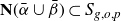 $\textbf{N}(\bar{\alpha} \cup \bar{\beta}) \subset S_{g,o,p}$
we would have
$\textbf{N}(\bar{\alpha} \cup \bar{\beta}) \subset S_{g,o,p}$
we would have
 $|\partial \textbf{N}| = p$
.
$|\partial \textbf{N}| = p$
.
We slightly modify our initial setup of
 $\alpha, \beta \subset S_1$
by requiring
$\alpha, \beta \subset S_1$
by requiring
 $|\alpha \cap \beta| = g + p -1$
. Thus,
$|\alpha \cap \beta| = g + p -1$
. Thus,
 $\beta$
is now a
$\beta$
is now a
 $\langle (g + p -1) ,1 \rangle$
curve on
$\langle (g + p -1) ,1 \rangle$
curve on
 $S_1$
while
$S_1$
while
 $\alpha$
is still a
$\alpha$
is still a
 $\langle 0,1 \rangle$
curve. This implies that
$\langle 0,1 \rangle$
curve. This implies that
 $S_1 \setminus (\alpha \cup \beta)$
has
$S_1 \setminus (\alpha \cup \beta)$
has
 $(g+p-1)$
discs components. We again denote a regular neighbourhood of
$(g+p-1)$
discs components. We again denote a regular neighbourhood of
 $\alpha \cup \beta$
by
$\alpha \cup \beta$
by
 $\textbf{N} (\subset S_1)$
. We choose any p of these discs components and place a single marked point in each. Doing so will designate p boundary components,
$\textbf{N} (\subset S_1)$
. We choose any p of these discs components and place a single marked point in each. Doing so will designate p boundary components,
 $\partial_1 , \ldots , \partial_p \subset \partial N$
—the boundary curves which bound once punctured discs, now in
$\partial_1 , \ldots , \partial_p \subset \partial N$
—the boundary curves which bound once punctured discs, now in
 $S_{1,p}$
.
$S_{1,p}$
.
We define a collection of
 $\gamma$
arcs,
$\gamma$
arcs,
 $\{\gamma_1 , \ldots , \gamma_n\}$
, as being a 1-handle attaching scheme in exactly the same manner as that of Section 3. As such we can consider the A-graph, G, of an attaching scheme. If
$\{\gamma_1 , \ldots , \gamma_n\}$
, as being a 1-handle attaching scheme in exactly the same manner as that of Section 3. As such we can consider the A-graph, G, of an attaching scheme. If
 $|G| = p$
with each connected sub-graph component being a tree where exactly one of its vertices corresponds to a
$|G| = p$
with each connected sub-graph component being a tree where exactly one of its vertices corresponds to a
 $\partial_i$
boundary component of
$\partial_i$
boundary component of
 $\textbf{N}$
, then the resulting curve pair,
$\textbf{N}$
, then the resulting curve pair,
 $(\alpha , \beta^\prime)$
, will be filling. And additionally, if
$(\alpha , \beta^\prime)$
, will be filling. And additionally, if
 \begin{align*}| \cup_1^n \gamma_i \cap \alpha| - n = g -1 , \end{align*}
the resulting pair,
 $(\alpha , \beta^\prime)$
, will be minimal, i.e.
$(\alpha , \beta^\prime)$
, will be minimal, i.e.
 $(g + p -1) + (g-1) = 2g + p -2$
. Since our third condition for an attaching scheme requires that the shear and splice operation produce a
$(g + p -1) + (g-1) = 2g + p -2$
. Since our third condition for an attaching scheme requires that the shear and splice operation produce a
 $\beta^\prime$
that coherently intersects
$\beta^\prime$
that coherently intersects
 $\alpha$
, we have our conditions for constructing minimal coherent filling pairs for
$\alpha$
, we have our conditions for constructing minimal coherent filling pairs for
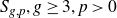 $S_{g,p}, g \geq 3, p\gt 0$
.
$S_{g,p}, g \geq 3, p\gt 0$
.
Theorem 7·1 (Also see [
Reference Jeffreys9
, theorem 1·3]). Minimal coherent filling pairs for
 $S_{g,p}, g \geq 3, p\gt 0$
, exist for all such g and p.
$S_{g,p}, g \geq 3, p\gt 0$
, exist for all such g and p.
Proof. Utilizing only the double 1-handle surgeries of Section 2, we take any 1-handle attaching scheme of
 $\gamma$
arcs that yields a minimal coherent filling pair for
$\gamma$
arcs that yields a minimal coherent filling pair for
 $S_{g+p}$
. We throw away any
$S_{g+p}$
. We throw away any
 $p-1$
edges of the associated tree graph, G, to produce a non-connected graph,
$p-1$
edges of the associated tree graph, G, to produce a non-connected graph,
 $G^\prime$
, which has p sub-graphs. We restrict our choices of discarded edges to those that correspond to single 1-handle surgery and the
$G^\prime$
, which has p sub-graphs. We restrict our choices of discarded edges to those that correspond to single 1-handle surgery and the
 $B_{NW/SW}$
handle of the double 1-handle surgery. The reader should observe that throwing away the
$B_{NW/SW}$
handle of the double 1-handle surgery. The reader should observe that throwing away the
 $B_{NW/SW}$
alters the double 1-handle surgery to a single 1-handle surgery.
$B_{NW/SW}$
alters the double 1-handle surgery to a single 1-handle surgery.
Thus, by construction there is a sub-collection of our original collection of
 $\gamma$
arcs that yield an attaching scheme that produces a surface of genus, g, with p boundary components. Moreover,
$\gamma$
arcs that yield an attaching scheme that produces a surface of genus, g, with p boundary components. Moreover,
 $G^\prime$
is the associated A-graph and this surface will be a regular neighbourhood of the resulting coherent filling pair four valent graph,
$G^\prime$
is the associated A-graph and this surface will be a regular neighbourhood of the resulting coherent filling pair four valent graph,
 $\alpha \cup \beta^\prime$
. Now by capping off each of the p boundary components with a once punctured disc, we obtain
$\alpha \cup \beta^\prime$
. Now by capping off each of the p boundary components with a once punctured disc, we obtain
 $S_{g,p}$
. Necessarily,
$S_{g,p}$
. Necessarily,
 $|\alpha \cap \beta^\prime |= 2g + p -2$
.
$|\alpha \cap \beta^\prime |= 2g + p -2$
.
One last subtle observation. We can designate one arbitrary vertex from each component of
 $G^\prime$
as corresponding to one of the p designated boundary components,
$G^\prime$
as corresponding to one of the p designated boundary components,
 $\partial_i$
. Placing a puncture in each associated disc of
$\partial_i$
. Placing a puncture in each associated disc of
 $S_1 \setminus (\alpha \cup \beta)$
, we can then have this
$S_1 \setminus (\alpha \cup \beta)$
, we can then have this
 $S_{1,p}$
with its coherent filling pair,
$S_{1,p}$
with its coherent filling pair,
 $(\alpha, \beta) $
, as the initial starting setup. The previous sub-collection of
$(\alpha, \beta) $
, as the initial starting setup. The previous sub-collection of
 $\gamma$
arcs will then be an attaching scheme that yields
$\gamma$
arcs will then be an attaching scheme that yields
 $(\alpha , \beta^\prime)$
as a minimal coherent filling pair in a
$(\alpha , \beta^\prime)$
as a minimal coherent filling pair in a
 $S_{g,p}$
surface.
$S_{g,p}$
surface.
Acknowledgements
We thank the authors of [ Reference Aougab, Menasco and Nieland2 ] for the use of Figure 1. This work has its genesis in the second author’s collaboration with Tarik Aougab and Mark Nieland and he thanks them for numerous discussion on the topic of this note. Finally, we are indebted to the tireless anonymous referee whose value-added efforts and suggestions are too numerous to list. But just to name two, Sections 5 and 6 are a direct result of the referee’s suggestions.


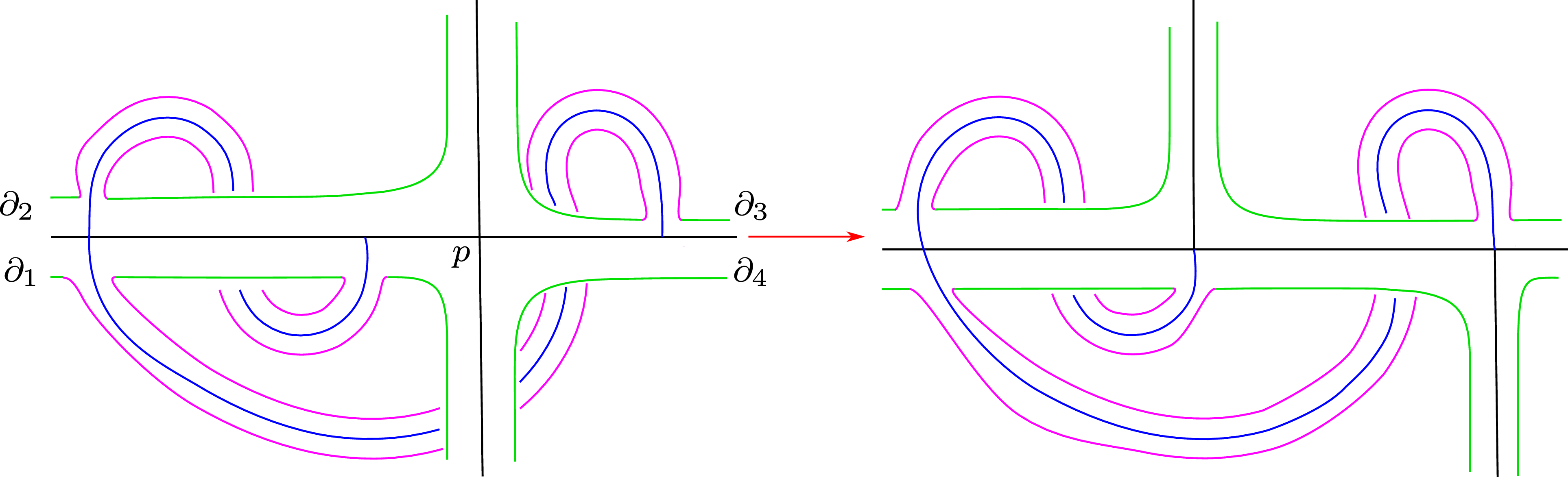
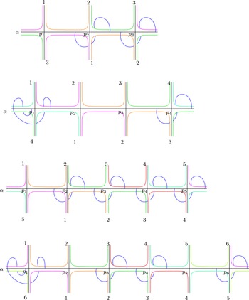


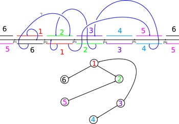


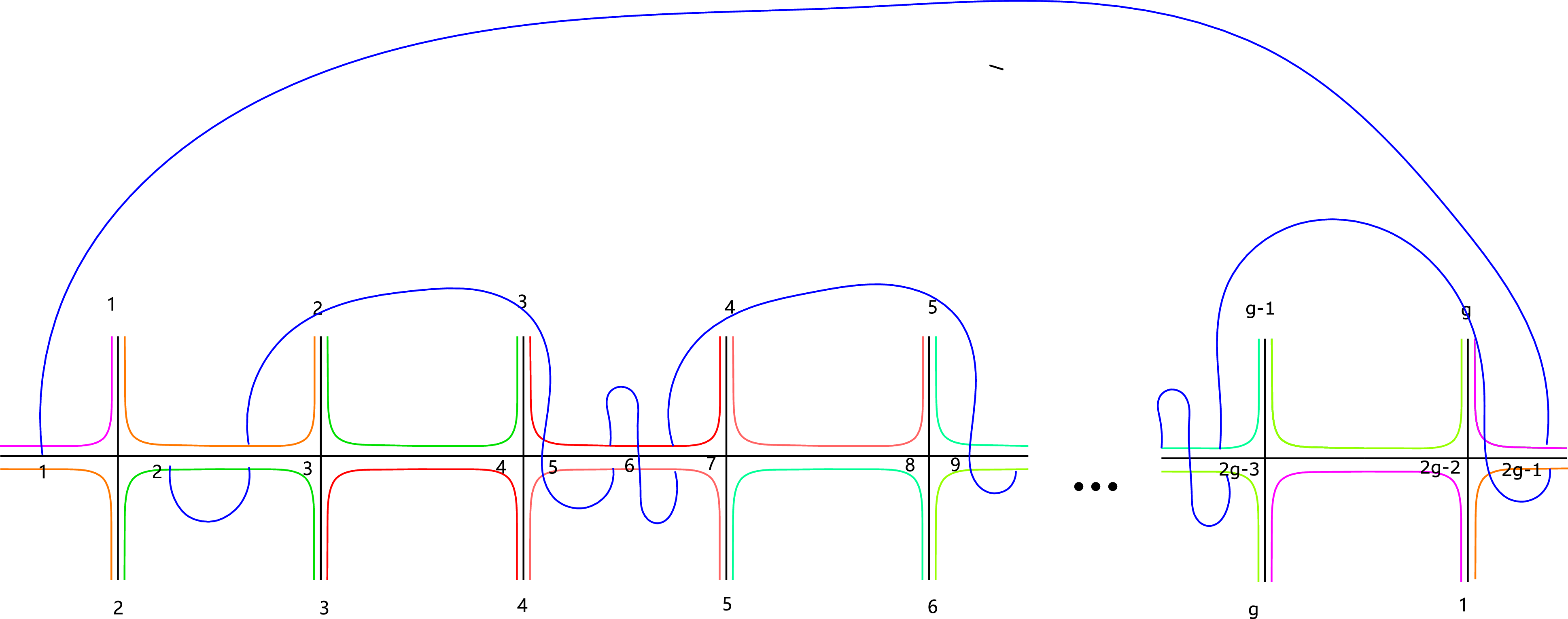
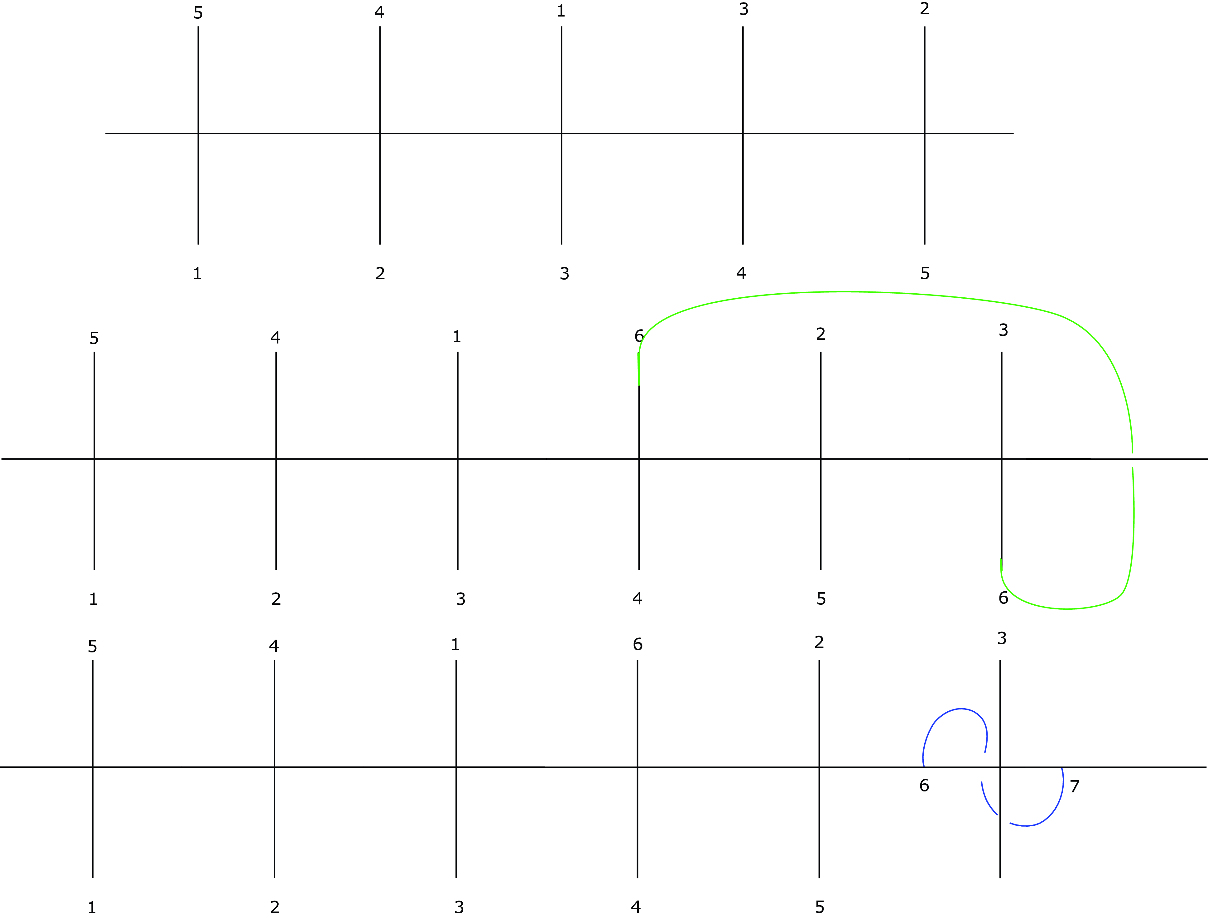
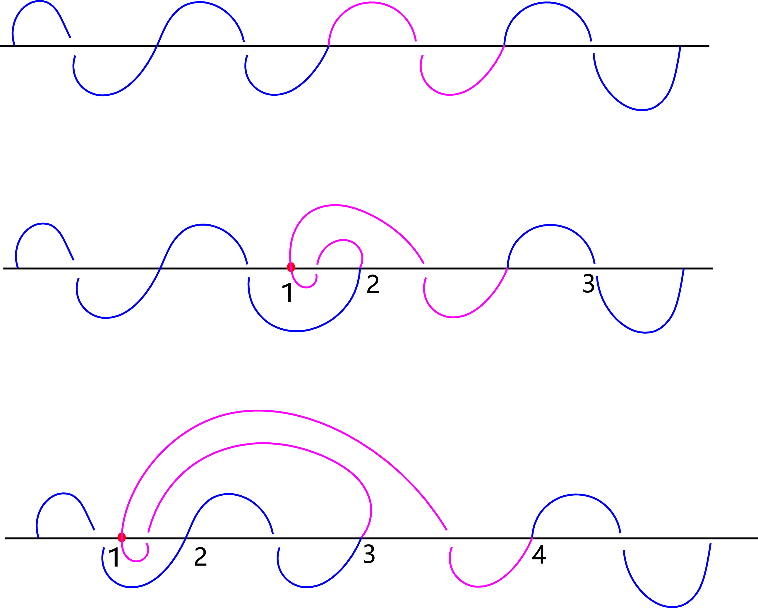
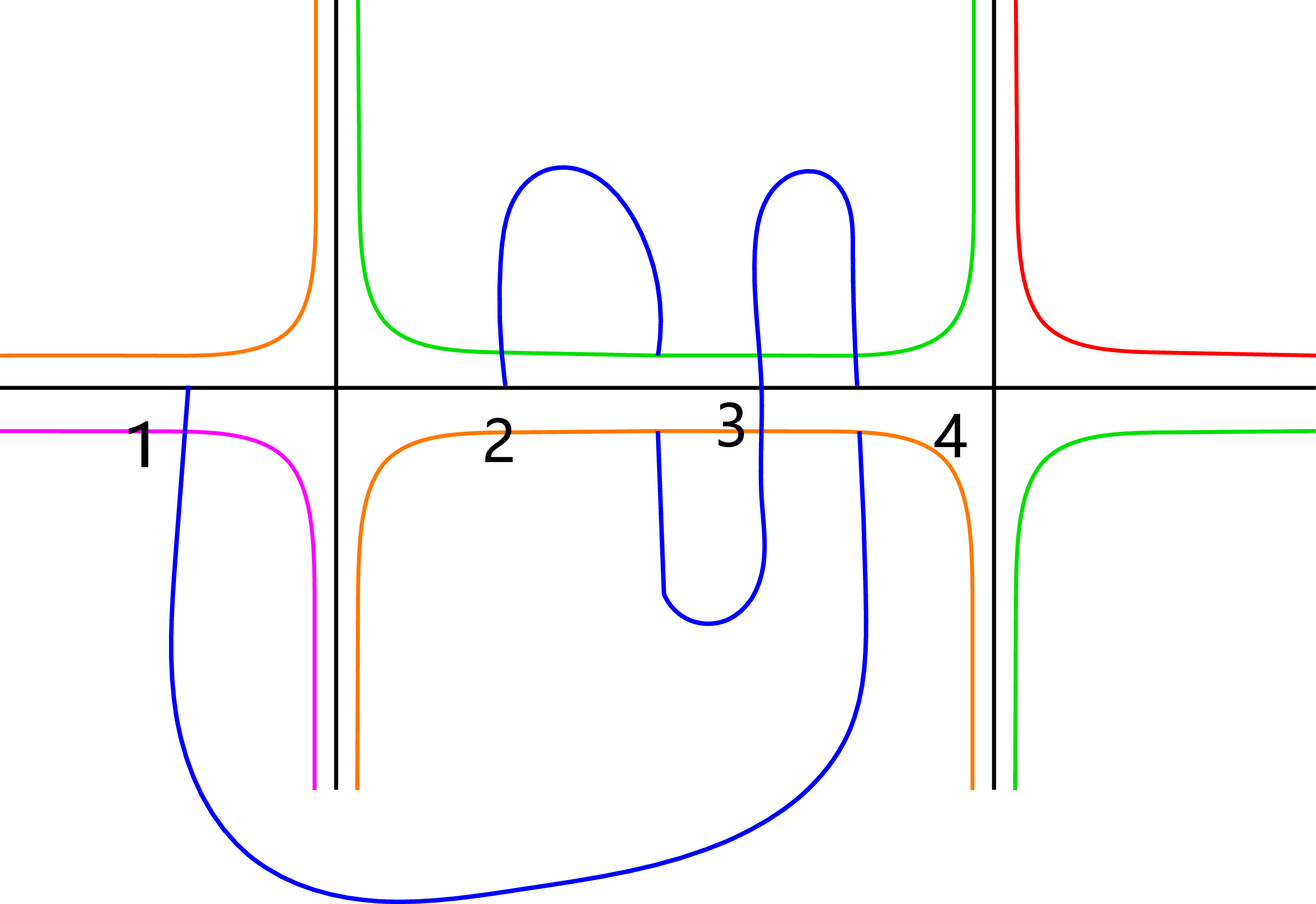

 Open access