

1 Introduction
Targets are one of the pillars of high-power laser experiments together with the laser facility, diagnostics, and theoretical and numerical tools. In the last decade, target designs have evolved (along with the other pillars) to enable the investigation of new physical phenomena. There are many designs, each specific to the phenomena investigated, the laser parameters and the diagnostic setup. Targets range in size from micrometres to millimetres, not counting possible associated diagnostic shielding, and can range in shape from a homogeneous dot to a layered planar structure, to a 3D object combining multiple shapes and materials. Laser–solid interactions are sensitive to perturbations of the order of the laser wavelength, so these shapes and some of their surfaces must be formed and joined with state-of-the-art precision. Therefore, developing a new target and validating its critical parameters often requires research and development, and different techniques are commonly combined for fabrication of a single-target type. Tens to hundreds of targets are required to support each experimental campaign, since they are usually destroyed in the interaction with the laser pulse.
The demand for such targets will be boosted in the near future by a number of new high-throughput pan-European advanced laser facilities. The High Energy Density (HED) instrument at the European XFEL is expected to start operating for users in 2018 with high-power lasers provided by HIBEF User Consortium (Helmholtz International Beamline for Extreme Fields). The Extreme Light Infrastructure (ELI-Beamlines, ELI Nuclear Physics and ELI-ALPS) is under development and will become operational in the next few years with similar shot rates. The European Synchrotron Radiation Facility (ESRF) has plans for laser-based HED activities, and high repetition rate national laser facilities are or will be soon in operation, e.g., Gemini (United Kingdom), Apollon (France) and CLPU (Spain). All of these facilities promise operation at repetition rates up to 1–10 Hz, corresponding to a requirement of 3600–36,000 targets per hour. Facilities would thus need to provide the supporting technologies for delivering different kinds of targets (such as gas jets, clusters, liquid crystals, and solid targets, some at cryogenic temperature), as well as ensuring the development of manufacturing facilities capable of producing them in the massive numbers and with the needed high precision. Moreover, a number of technological issues will be raised or enhanced by high repetition rate experiments, for example: fast target refreshing, positioning and alignment; real time target characterization and sorting; target debris shielding of laser optics; target cleaning, target chamber nuclear activation, and gas and heat loading of the target chamber. The severity of these issues depends on laser properties, which differ for each class of experiments. For example, the activation and electromagnetic pulses (EMPs) produced by ultra-high-intensity laser pulses for HED experiments are not a problem where intensities below $10^{18}~\text{W}/\text{cm}^{2}$
are used. Nor is target fratricide a major issue for pulse energies lower than 1 J. In general, target availability and high repetition rate issues could very likely become a limiting factor in exploiting the full potential of advanced laser and X-ray facilities.
$10^{18}~\text{W}/\text{cm}^{2}$
are used. Nor is target fratricide a major issue for pulse energies lower than 1 J. In general, target availability and high repetition rate issues could very likely become a limiting factor in exploiting the full potential of advanced laser and X-ray facilities.
In this paper, we report on target needs for specific science cases of interest for the high-power laser community (Section 2). In Sections 3 and 4 we discuss target fabrication challenges and technical issues related to high repetition rate operation. Current target supply models and possible future strategies for target supply in advanced laser facilities are illustrated in Section 5. Finally, our conclusions are outlined in Section 6.
2 Target needs
This section gives a general introduction to users’ target needs for three science cases of particular interest for the high-power laser community. Section 2.1 considers targets designed to reach extreme pressure and temperature states by shock or ramp compression, using direct irradiation by long (100 ps–tens of ns), high-energy (J–kJ) laser pulses. In Section 2.2, experiments using shorter, high-intensity pulses (ps-fs, $10^{18}~\text{W}/\text{cm}^{2}$
) are described, where the laser heats a sample indirectly by driving hot electrons or ions, giving heating at a constant volume (isochoric). Finally, Section 2.3 looks at using high-intensity and high-energy laser pulses to drive particle and radiation beams, requiring similar targets but with a focus on consistency and reproducibility of the sources.
$10^{18}~\text{W}/\text{cm}^{2}$
) are described, where the laser heats a sample indirectly by driving hot electrons or ions, giving heating at a constant volume (isochoric). Finally, Section 2.3 looks at using high-intensity and high-energy laser pulses to drive particle and radiation beams, requiring similar targets but with a focus on consistency and reproducibility of the sources.
2.1 Targets for dynamic compression physics
Dynamic compression physics is one of the largest science fields studied at high-energy laser facilities[Reference Remington, Rudd and Wark1]. In such experiments, laser pulses with several J up to kJ of energy and durations between 100 ps and tens of ns compress solid density matter samples to extreme pressure (hundreds of GPa) and temperature (several 1000 K up to $10^{4}~\text{K}$
and more) conditions. These conditions can be achieved with the direct ablation technique: the laser impinging onto the target surface produces a plasma which rapidly expands, driving a corresponding shock wave into the target via the rocket effect, heating it and compressing it.
$10^{4}~\text{K}$
and more) conditions. These conditions can be achieved with the direct ablation technique: the laser impinging onto the target surface produces a plasma which rapidly expands, driving a corresponding shock wave into the target via the rocket effect, heating it and compressing it.
Prototypical experiments for investigating the properties of matter at such extreme pressure and temperature states include equation of state (EOS) measurements, study of high-pressure/high-temperature phase diagrams and new superdense phases[Reference Zeĺdovich and Raizer2], phase transition processes and kinetics (for instance: grain nucleation and growth in extreme conditions)[Reference Coppari, Smith, Eggert, Wang, Rygg, Lazicki, Hawreliak, Collins and Duffy3], mechanisms of solid deformation at high strain rate[Reference Milathianaki, Boutet, Williams, Higginbotham, Ratner, Gleason, Messerschmidt, Seibert, Swift, Hering, Robinson, White and Wark4], transitions between solids and warm dense liquids[Reference Hicks, Boehly, Eggert, Miller, Celliers and Collins5], and the structure of those liquids[Reference Kraus, Vorberger, Gericke, Bagnoud, Blažević, Cayzac, Frank, Gregori, Ortner, Otten, Roth, Schaumann, Schumacher, Siegenthaler, Wagner, Wünsch and Roth6]. Besides the intrinsic interest for material science, these studies find application in planetary physics, astrophysics, inertial confinement fusion (ICF) and laser-based industrial processes[Reference Fortov7]. For example, a sophisticated knowledge of matter properties at pressures around 10 Mbar is required in order to reliably model the cores of giant gaseous planets such as Jupiter and Saturn, and large rocky exoplanets[Reference Guillot8]. In particular, the chemistry of low- and mid-Z material mixtures at high-pressure/high-temperature conditions strongly influences the formation and evolution of planets in extrasolar systems[Reference Cavazzoni, Chiarotti, Scandolo, Tosatti, Bernasconi and Parrinello9]. On shorter timescales, similar conditions are also present in meteor impacts[Reference Kraus, Ravasio, Gauthier, Gericke, Vorberger, Frydrych, Helfrich, Fletcher, Schaumann, Nagler, Barbrel, Bachmann, Gamboa, Göde, Granados, Gregori, Lee, Neumayer, Schumaker, Döppner, Falcone, Glenzer and Roth10] or collisions of planetoids[Reference Sekine, Ozaki, Miyanishi, Asaumi, Kimura, Albertazzi, Sato, Sakawa, Sano, Sugita and Matsui11]. Other fundamental physical phenomena under investigation include dynamic properties of warm dense matter (WDM) in general, anisotropy of shock propagation, solid and liquid phase transitions. In addition to the prototypical Hugoniot shock compression[Reference Knudson and Desjarlais12], a wide variety of compression schemes exist such as quasi-isentropic (ramp) compression[Reference Smith, Eggert, Jeanloz, Duffy, Braun, Patterson, Rudd, Biener, Lazicki, Hamza, Wang, Braun, Benedict, Celliers and Collins13], multiple-shock[Reference Boehly, Goncharov, Seka, Barrios, Celliers, Hicks, Collins, Hu, Marozas and Meyerhofer14], decaying shocks[Reference Hicks, Boehly, Eggert, Miller, Celliers and Collins5], reverberating[Reference Nellis, Weir and Mitchell15] and colliding[Reference Zastrau, Gamboa, Kraus, Benage, Drake, Efthimion, Falk, Falcone, Fletcher, Galtier, Gauthier, Granados, Hastings, Heimann, Hill, Keiter, Lu, MacDonald, Montgomery, Nagler, Pablant, Schropp, Tobias, Gericke, Glenzer and Lee16] shocks. These schemes are usually based on specific geometries, laser temporal profiles and target designs.
Schematic view of the experimental setup used at the MEC endstation of the LCLS to study dynamic compression of graphite samples to pressures between 20 and 230 GPa. The VISAR system recorded the shock transit time providing information on the shock velocity. The microscopic state was probed by XRD. Image reproduced from Ref. [Reference Kraus, Ravasio, Gauthier, Gericke, Vorberger, Frydrych, Helfrich, Fletcher, Schaumann, Nagler, Barbrel, Bachmann, Gamboa, Göde, Granados, Gregori, Lee, Neumayer, Schumaker, Döppner, Falcone, Glenzer and Roth10], licensed under CC-BY 4.0[19].
When investigating matter in extreme states, well-understood optical diagnostics are generally used to determine the conditions that the sample has been driven to. These are primarily Velocity Interferometer System for Any Reflector (VISAR) to measure the shock velocity and transit times and extract the density and pressure from known EOS relations, and Streaked Optical Pyrometery (SOP) for the temperature. More recently, X-ray diagnostics brought new capabilities to further understand the atomic and microscopic structures of the bulk of the compressed matter. On laser only facilities, laser–plasma backlighters can be used to measure X-ray diffraction (XRD), wide angle X-ray scattering (WAXS) and small angle X-ray scattering (SAXS) patterns, as well as absorption spectra in X-ray absorption near edge structure (XANES) and extended X-ray absorption fine structure (EXAFS), or direct imaging by X-rays. With the development of X-ray-free electron lasers (XFELs), energy-resolved scattering has become more easily accessible, using inelastic X-ray scattering (IXS) and X-ray Thomson scattering (XRTS), while still being able to utilize optical diagnostics[Reference Glenzer, Fletcher, Galtier, Nagler, Alonso-Mori, Barbrel, Brown, Chapman, Chen, Curry, Fiuza, Gamboa, Gauthier, Gericke, Gleason, Goede, Granados, Heimann, Kim, Kraus, MacDonald, Mackinnon, Mishra, Ravasio, Roedel, Sperling, Schumaker, Tsui, Vorberger, Zastrau, Fry, White, Hasting and Lee17, Reference Fletcher, Lee, Döppner, Galtier, Nagler, Heimann, Fortmann, LePape, Ma, Millot, Pak, Turnbull, Chapman, Gericke, Vorberger, White, Gregori, Wei, Barbrel, Falcone, Kao, Nuhn, Welch, Zastrau, Neumayer, Hastings and Glenzer18]. Various geometries can be used, with the X-rays and optical beam co-linear, transverse or at other angles and multiple optical beams can drive counter-propagating shocks. Figure 1 shows an example of experimental setup combining VISAR and XRD diagnostics to study shock compression of graphite samples at the Matter at Extreme Conditions (MEC) endstation of the Linac Coherent Light Source (LCLS). In each case, target design must be able to accommodate multiple diagnostics, taking into account the shock geometry and laser parameters.
The repetition rate of current shock-compression experiments at combined laser–X-ray facilities is of the order of about 1 shot/10 min to 1 shot/min and the typical number of shots of an experimental campaign is of the order of 100–500. At laser only facilities, the repetition rate can be lower (shot/h or even shot/day), therefore the number of samples needed for an experiment can be considerably lower. The possibility of reaching higher repetition rates (0.1 Hz or better) and collecting data on a larger number of shots would offer new perspectives in this field, for example in the investigation of materials with poor scattering properties (i.e., low-Z materials, liquids), in the study of compression pathways and phase kinetics, and in the collection of data points along the Hugoniot and ramp compression curves. In addition, higher repetition rates would allow for accumulating better statistics for synchrotron radiation and XFEL diagnostics and better spatial as well as spectral resolution for IXS and XRTS, or scanning X-ray parameters such as the X-ray energy for EXAFS.
Target design and optimization are in general carried out by the user group or collaboration. A specific design has to be made to achieve the desired thermodynamic states while taking into account the laser parameters and diagnostics requirements (geometry, atomic and microscopic structures for X-rays, optical windows and properties for VISAR and SOP). Target needs appear quite homogeneous across the community and similar target structures are used by different groups working at both XFEL and synchrotron radiation facilities. Typical targets used for laser compression experiments are either single component foils (whether polycrystalline or single crystal) up to $200~\unicode[STIX]{x03BC}\text{m}$
thick, sometimes with thin coating, or multilayer samples. In the latter configuration, the sample is enclosed in a sandwich structure (see Figure 2) including: an ablator, a shield (if needed), the sample itself and a window.
$200~\unicode[STIX]{x03BC}\text{m}$
thick, sometimes with thin coating, or multilayer samples. In the latter configuration, the sample is enclosed in a sandwich structure (see Figure 2) including: an ablator, a shield (if needed), the sample itself and a window.
Examples of typical multilayer targets used for dynamic compression physics experiments: (a) in the simplest configuration the sample is coated with a low-Z layer (ablator), and occasionally with a preheat layer; (b) placing the sample layer between solid plates prevents expansion and maintains high-pressure conditions longer; (c) complex sample allows measurement of shock pressure by VISAR reflection from pressure standard (quartz) while also containing the sample.
The advantage of using an ablator, instead of directly ablating the sample, is to confine the laser-produced coronal plasma to the front layer and therefore to reduce gradients in the sample under investigation. Also, a proper choice of the ablation material helps in reaching extreme high pressure as a result of impedance mismatching. Finally it mitigates pre-heating in the sample and helps smoothing of small-scale spatial variations of the laser beam. Typical ablators are plastics, such as Parylene N, polyethylene and polypropylene, or aluminium[Reference Swift and Krauss20].
The sample thickness should be optimized for the X-ray diagnostics and laser properties as well as for the time scale of the phenomena under investigation. For example, the attenuation length of X-rays in the target material must be taken into account to avoid loss of signal due to X-ray absorption in the sample. Another important aspect is that the ablator and back window must adhere perfectly to the sample to avoid surface roughness, cracks and porosity and therefore prevent distorted shock front and thermodynamic inhomogeneities. A good adherence is generally obtained with coating techniques or using a thin glue layer. The latter should be avoided at the sample–window interface which is important for VISAR measurements.
Windows are used to act as a tamper and to maintain the thermodynamic conditions avoiding strong release in vacuum. The window should be transparent both to X-rays and visible light for the diagnostics not only at ambient conditions but also under compression (i.e., diamond, which is optimal for X-ray transmission, becomes opaque around 100 GPa). Typical window materials are quartz, lithium fluoride, sapphire and diamond. The window rear face should have an antireflection (AR) coating for the VISAR probe laser.
A high-Z shield layer might be necessary to prevent pre-heating from hard X-rays emitted by the laser-produced coronal plasma.
The thickness of the different layers has to be optimized to ensure that homogeneous thermodynamic conditions are maintained for longer than the time scale of the process to be observed or of the X-ray probe duration (typically several hundreds of ps for synchrotrons and several hundreds of fs for XFELs). In addition, if a sample is too thick, release waves from the ablating material may dramatically reduce the pressure in a portion of the sample. A sandwich target can also be designed to reach off-Hugoniot states or to sustain the peak pressure for longer time (few ns)[Reference Torchio, Occelli, Mathon, Sollier, Lescoute, Videau, Vinci, Benuzzi-Mounaix, Headspith, Helsby, Bland, Eakins, Chapman, Pascarelli and Loubeyre21]. In this case, the sample can be embedded between two layers of a material with impedance similar to the studied sample. However, the total target thickness should not be too large with respect to the laser spot size to avoid shock front erosion from the borders[Reference Swift and Krauss20]. Also, as already mentioned, the thickness of the multilayers has to be adapted for X-ray diagnostics.
Hydrodynamic codes are currently used to model the wave interactions within the target, such as for example Multi[Reference Ramis, Schmalz and Meyer-ter-vehn22], Esther[Reference Colombier, Combis, Bonneau, Le Harzic and Audouard23] and Hyades[Reference Larsen and Lane24]. These codes simulate the laser–matter interaction by calculating energy deposition, hydrodynamics and mechanics, thermal conductivity, and radiation transfer, using available data of EOS, materials opacity, optical index and emissivity. At the moment, few hydrodynamic codes are freely available for the community, although other codes can be requested directly from the authors or purchased with licence. 2D codes also exist and can be used to check the planarity of the shock wave propagating in the sample[Reference Ramis, Meyer-ter-Vehn and Ramírez25, Reference Atzeni, Schiavi, Califano, Cattani, Cornolti, Del Sarto, Liseykina, Macchi and Pegoraro26]. By expanding the capabilities to a wider range of academic users, the hydrocodes could benefit from being made more accessible, user-friendly and with improved documentation. In addition, effects of phase transitions, grain size, pores, speckles in the laser, are generally not included in these codes and models would require more detailed input (i.e., EOS, phase transitions).
Target fabrication and characterization techniques (and the resulting quality, reproducibility and cost of the samples) need to be taken into account in the target design phase. As a consequence, iterations between users and target fabrication groups or companies are needed to develop a final target design. In the optimal case, target production can be completed using coating techniques, as for example: physical vapour deposition (PVD) for metallic films, chemical vapour deposition (CVD) for compounds (including electron beam CVD for oxides and salt structures deposition) and Parylene deposition. However, coating processes only grow layers with thickness up to approximately $30~\unicode[STIX]{x03BC}\text{m}$
(depending on the coating composition and on the substrate) and growing single crystals can be complicated and expensive. Therefore, targets are often assembled by gluing the above-mentioned layers with ordinary glue, formvar-based glue or UV-cured adhesives. In most cases, different laboratories and companies are involved in the production of a single batch of targets. For example, the production of iron–nickel alloy samples with a double diamond window, an AR coating and an ablator (illustrated in Figure 3) for experiments performed at ESRF was split into four processing phases performed by four different companies: (i) diamond windows production (Applied Diamonds, 6 weeks), (ii) AR deposit (Fichou, 3 weeks), (iii) deposit of the iron–nickel alloy (DEPHIS, 9 weeks) and (iv) polymer coating for ablator (Scitech, 3 weeks). This approach resulted in a long preparation time (5 months only for processing) and in an increase of the sample cost (more than 300 Euro/target). In general, a rough estimate of the cost of targets for shock-compression experiments ranges between
$30~\unicode[STIX]{x03BC}\text{m}$
(depending on the coating composition and on the substrate) and growing single crystals can be complicated and expensive. Therefore, targets are often assembled by gluing the above-mentioned layers with ordinary glue, formvar-based glue or UV-cured adhesives. In most cases, different laboratories and companies are involved in the production of a single batch of targets. For example, the production of iron–nickel alloy samples with a double diamond window, an AR coating and an ablator (illustrated in Figure 3) for experiments performed at ESRF was split into four processing phases performed by four different companies: (i) diamond windows production (Applied Diamonds, 6 weeks), (ii) AR deposit (Fichou, 3 weeks), (iii) deposit of the iron–nickel alloy (DEPHIS, 9 weeks) and (iv) polymer coating for ablator (Scitech, 3 weeks). This approach resulted in a long preparation time (5 months only for processing) and in an increase of the sample cost (more than 300 Euro/target). In general, a rough estimate of the cost of targets for shock-compression experiments ranges between $10^{4}$
and
$10^{4}$
and $10^{5}$
Euro/campaign, mainly in labour costs. In some cases, home-made targets are used: as-purchased rolled foils are glued to plastic ablators with thin glue layers. However, the quality, reproducibility and thickness uniformity of the additional adhesive layers are critical for the interpretation of experimental results, as they can lead to nonhomogeneous shock front and to different break-out times (i.e., time that the shock takes to reach the rear target surface). Gluing techniques can also prevent mass production of targets. In general, reproducibility within a few percents is desired for layer properties (especially thickness and density) and the initial thickness, density, crystalline phase, orientation, texture, grain size, reflectivity and composition of layers must be characterized in advance. As mentioned before, another important factor is the quality of the interface between sample and transparent windows, calling for specific surface treatments when possible since polished surfaces enhance the shock uniformity. Separation of targets produced in large sheets is usually performed by laser cutting or a focused ion beam (FIB). Other techniques used by specialized target fabrication groups and companies include laser cutting, surface polishing (including ion polishing), thermal fusing, lithography, etching, laser drilling and micromachining.
$10^{5}$
Euro/campaign, mainly in labour costs. In some cases, home-made targets are used: as-purchased rolled foils are glued to plastic ablators with thin glue layers. However, the quality, reproducibility and thickness uniformity of the additional adhesive layers are critical for the interpretation of experimental results, as they can lead to nonhomogeneous shock front and to different break-out times (i.e., time that the shock takes to reach the rear target surface). Gluing techniques can also prevent mass production of targets. In general, reproducibility within a few percents is desired for layer properties (especially thickness and density) and the initial thickness, density, crystalline phase, orientation, texture, grain size, reflectivity and composition of layers must be characterized in advance. As mentioned before, another important factor is the quality of the interface between sample and transparent windows, calling for specific surface treatments when possible since polished surfaces enhance the shock uniformity. Separation of targets produced in large sheets is usually performed by laser cutting or a focused ion beam (FIB). Other techniques used by specialized target fabrication groups and companies include laser cutting, surface polishing (including ion polishing), thermal fusing, lithography, etching, laser drilling and micromachining.
Scheme of iron–nickel alloy samples produced for ESRF experiments using an integrated process including four steps performed by different companies.
2.2 Targets for electron transport and isochoric heating
Investigation of the processes by which energy can be transferred into a dense plasma is, because of the plasma’s opacity, as big a field as the study of the properties of the heated plasma. In this area, energy requirements and time constraints require laser pulses with energy 1–1000 J, pulse length below 1 ps and intensity above $10^{18}~\text{W}/\text{cm}^{2}$
. Such pulses ionize the target (stopping the light at the surface) converting a fraction of the laser energy into relativistic electrons with temperatures up to few MeV, which transfer energy deeper into the target[Reference Kluge, Cowan, Debus, Schramm, Zeil and Bussmann27]. For high contrast pulses with tens of fs duration the main pulse interacts with an intact target surface (hundreds of nm preplasma). The target is static during the pulse; no electron recirculation, bulk heating or ion expansion occurs for that time. For longer pulses (ps) the target surface starts expanding before the interaction is over, thus relativistic oscillations of the critical density surface, electron recirculation and bulk heating take place during the interaction[Reference Paradkar28]. In both cases, the hot laser-generated electrons propagate into the bulk of the material in timescales much shorter than the plasma hydrodynamic expansion, and gives rise to intense electromagnetic fields and charge separation effects. As a consequence, a return current of low temperature bulk electrons (up to MA) is generated, which is responsible for Ohmic heating of the target bulk[Reference Glinsky29–Reference Huang, Kluge and Cowan31]. Therefore, extreme matter states with near solid density and extremely high temperatures are generated before the target expands significantly. These states are known as WDM (temperatures up to a few keV, see also Section 2.1), or HED states (energy density above
$10^{18}~\text{W}/\text{cm}^{2}$
. Such pulses ionize the target (stopping the light at the surface) converting a fraction of the laser energy into relativistic electrons with temperatures up to few MeV, which transfer energy deeper into the target[Reference Kluge, Cowan, Debus, Schramm, Zeil and Bussmann27]. For high contrast pulses with tens of fs duration the main pulse interacts with an intact target surface (hundreds of nm preplasma). The target is static during the pulse; no electron recirculation, bulk heating or ion expansion occurs for that time. For longer pulses (ps) the target surface starts expanding before the interaction is over, thus relativistic oscillations of the critical density surface, electron recirculation and bulk heating take place during the interaction[Reference Paradkar28]. In both cases, the hot laser-generated electrons propagate into the bulk of the material in timescales much shorter than the plasma hydrodynamic expansion, and gives rise to intense electromagnetic fields and charge separation effects. As a consequence, a return current of low temperature bulk electrons (up to MA) is generated, which is responsible for Ohmic heating of the target bulk[Reference Glinsky29–Reference Huang, Kluge and Cowan31]. Therefore, extreme matter states with near solid density and extremely high temperatures are generated before the target expands significantly. These states are known as WDM (temperatures up to a few keV, see also Section 2.1), or HED states (energy density above $100~\text{kJ}/\text{cm}^{3}$
).
$100~\text{kJ}/\text{cm}^{3}$
).
WDM and HED experiments look at the structure and energy flow between the various components of the plasma. Specific HED science questions include understanding the type and growth of instabilities at the plasma surface and energetic particle transport within it, energy interchange between highly energetic particles, ambient electrons, nuclei and photons. These kinds of experiments find application in laboratory astrophysics, study of relativistic plasmas (instabilities), inertial fusion studies, and investigation of the fundamental physics of laser-driven particle and radiation sources (see Section 2.3).
The number of shots required for electron transport and isochoric heating experiments depends on the specific experiment. In general, tens of shots are needed for tracing the thermal and structural evolution of the system in time. This number can grow if the effect being investigated is small compared to shot-to-shot or sample-to-sample variations, or if the added variance (due to instabilities or chaotic process) is the parameter being studied. Parameter scans are normally performed to determine the dependence of system evolution on initial target properties and laser parameters. For these cases, the total number of shots per campaign might encompass thousands of individual shots. The shot repetition rate in current facilities (typically much lower than $1~\text{min}^{-1}$
) is too low to allow such experiments.
$1~\text{min}^{-1}$
) is too low to allow such experiments.
HED and WDM experiments involve targets that are sufficiently large and/or dense for reasonable opacity and that endure for sufficiently long to approach equilibrium. A variety of approaches (singly or in combination) are used for coupling energy in through the surface; for example, cones to concentrate the light and resulting electrons; modulated surface topology, density and/or atomic number to focus EM fields (such modulations can also be produced by fielding with prepulses with known properties). In some cases structures can be built into the target to enable detection of, for example, hot-electron–stimulated fluorescence or a buried layer expansion. X-ray radiation from XFEL or laser-driven (secondary) sources can be used for diagnostics since X-ray scattering techniques are sensitive to nuclear positions and density fluctuations, either thermal or caused by concerted particle motions. Laser-driven proton sources can be used not only to measure electromagnetic fields generated by concerted particle motion, but also to modify the target surface density and atomic number profiles. The use of secondary radiation sources to probe WDM and HED states (pump–probe experiments) requires secondary targets (backlighters) for tailoring or converting the primary (photon) beam to more appropriate excitations (narrow band fluorescence, protons, X-rays). As a result, the completed target assemblies often require addition of a 3D superstructure in the mm scale (multi-target assembly). Target superstructure can also be used for shielding the detector while giving access to the target region under investigation. Figure 4 shows an example of multi-target configuration used to investigate proton-driven isochoric heating of polycrystalline graphite rods $(125~\unicode[STIX]{x03BC}\text{m}\times 300~\unicode[STIX]{x03BC}\text{m}\times 3~\text{mm})$
. Protons were produced by the interaction of a laser pulse with a thin Au foil, while the X-ray probe was generated by the interaction of a laser pulse with a Ti foil. An Au shield was required to block secondary radiation produced in the laser–matter interaction[Reference Pelka, Gregori, Gericke, Vorberger, Glenzer, Günther, Harres, Heathcote, Kritcher, Kugland, Li, Makita, Mithen, Neely, Niemann, Otten, Riley, Schaumann, Schollmeier, Tauschwitz and Roth32].
$(125~\unicode[STIX]{x03BC}\text{m}\times 300~\unicode[STIX]{x03BC}\text{m}\times 3~\text{mm})$
. Protons were produced by the interaction of a laser pulse with a thin Au foil, while the X-ray probe was generated by the interaction of a laser pulse with a Ti foil. An Au shield was required to block secondary radiation produced in the laser–matter interaction[Reference Pelka, Gregori, Gericke, Vorberger, Glenzer, Günther, Harres, Heathcote, Kritcher, Kugland, Li, Makita, Mithen, Neely, Niemann, Otten, Riley, Schaumann, Schollmeier, Tauschwitz and Roth32].
Schematic layout of the experimental configuration used to investigate proton-driven isochoric heating of polycrystalline graphite rods $(125~\unicode[STIX]{x03BC}\text{m}\times 300~\unicode[STIX]{x03BC}\text{m}\times 3~\text{mm})$
. Reprinted figure with permission from Ref. [Reference Pelka, Gregori, Gericke, Vorberger, Glenzer, Günther, Harres, Heathcote, Kritcher, Kugland, Li, Makita, Mithen, Neely, Niemann, Otten, Riley, Schaumann, Schollmeier, Tauschwitz and Roth32]. Copyright 2010 by the American Physical Society.
$(125~\unicode[STIX]{x03BC}\text{m}\times 300~\unicode[STIX]{x03BC}\text{m}\times 3~\text{mm})$
. Reprinted figure with permission from Ref. [Reference Pelka, Gregori, Gericke, Vorberger, Glenzer, Günther, Harres, Heathcote, Kritcher, Kugland, Li, Makita, Mithen, Neely, Niemann, Otten, Riley, Schaumann, Schollmeier, Tauschwitz and Roth32]. Copyright 2010 by the American Physical Society.
Hereinafter, we report a few examples of possible targets exploiting specific geometries or layer sequences for the investigation of isochoric heating and electron transport mechanisms.
Hollow cone structures can be used to guide light and photo-generated electrons into a target at its tip. MeV electrons in the cone are generated via a direct light pressure acceleration mechanism, that increases the number and energy of electrons reaching the cone tip and heating it. For p-polarized radiation (i.e., electric field perpendicular to the cone wall), bunches of electrons are pulled from the cone surface towards the centre of the cone where they are accelerated by the Lorentz force[Reference Kluge, Gaillard, Flippo, Burris-Mog, Enghardt, Gall, Geissel, Helm, Kraft, Lockard, Metzkes, Offermann, Schollmeier, Schramm, Zeil, Bussmann and Cowan33]. Depending on the shape of the target at the cone tip, different effects can be studied. For example, a reduced mass target at the cone tip enhances proton acceleration performances[Reference Gaillard, Kluge, Flippo, Bussmann, Gall, Lockard, Geissel, Offermann, Schollmeier, Sentoku and Cowan34]. In this configuration, the Target Normal Sheath Acceleration (TNSA) field (see Section 2.3) is due to two electron populations, produced in the cone and at the reduced mass target surface. Figure 5 shows qualitatively the spatial distribution of electric field and electron energy density for flat-top cone targets. Another possibility is to use a thin wire positioned at the tip of a hollow cone and aligned along the cone axis or at some angle, as shown in Figure 6. In this geometry, the cone guides the laser light and laser-generated hot electrons into the wire, increasing their energy density by more than one order of magnitude[Reference Kodama, Sentoku, Chen, Kumar, Hatchett, Toyama, Cowan, Freeman, Fuchs, Izawa, Key, Kitagawa, Kondo, Matsuoka, Nakamura, Nakatsutsumi, Norreys, Norimatsu, Snavely, Stephens, Tampo, Tanaka and Yabuuchi35].
Qualitative spatial distributions of electric field (left) and electron energy density (right) produced by the interaction of an ultra-intense laser pulse with a flat-top cone target. From T. Kluge.
(a) Hollow cone target with thin wire at the tip (diameter $5~\unicode[STIX]{x03BC}\text{m}$
, length 1 mm): the black line shows a wire aligned along the cone axis, the dashed line represents a wire tilted by
$5~\unicode[STIX]{x03BC}\text{m}$
, length 1 mm): the black line shows a wire aligned along the cone axis, the dashed line represents a wire tilted by $15^{\circ }$
from the cone axis (size bar is
$15^{\circ }$
from the cone axis (size bar is $300~\unicode[STIX]{x03BC}\text{m}$
). Spatial distribution of electrons with energy above 3.5 MeV for a wire positioned along (b) the cone axis and (c) tilted by
$300~\unicode[STIX]{x03BC}\text{m}$
). Spatial distribution of electrons with energy above 3.5 MeV for a wire positioned along (b) the cone axis and (c) tilted by $15^{\circ }$
. Reprinted with permission from Macmillian Publishers Ltd: Nature[Reference Kodama, Sentoku, Chen, Kumar, Hatchett, Toyama, Cowan, Freeman, Fuchs, Izawa, Key, Kitagawa, Kondo, Matsuoka, Nakamura, Nakatsutsumi, Norreys, Norimatsu, Snavely, Stephens, Tampo, Tanaka and Yabuuchi35], copyright 2004.
$15^{\circ }$
. Reprinted with permission from Macmillian Publishers Ltd: Nature[Reference Kodama, Sentoku, Chen, Kumar, Hatchett, Toyama, Cowan, Freeman, Fuchs, Izawa, Key, Kitagawa, Kondo, Matsuoka, Nakamura, Nakatsutsumi, Norreys, Norimatsu, Snavely, Stephens, Tampo, Tanaka and Yabuuchi35], copyright 2004.
2D spatial distribution of free electron density and longitudinal electrostatic field at 43 fs prior to the peak laser intensity on the target. The density distribution shows that internal expansions compress the CD $_{2}$
layer to a higher density with a factor of about 1.5. The compression is also associated with enhanced ion heating in the compression layers. Strong ripples and filaments are clearly seen in the front surface and bulk of the buried layer target. The detailed simulation parameters and physics can be found in Huang et al.
[Reference Huang, Bussmann, Kluge, Lei, Yu and Cowan38]. From L. G. Huang.
$_{2}$
layer to a higher density with a factor of about 1.5. The compression is also associated with enhanced ion heating in the compression layers. Strong ripples and filaments are clearly seen in the front surface and bulk of the buried layer target. The detailed simulation parameters and physics can be found in Huang et al.
[Reference Huang, Bussmann, Kluge, Lei, Yu and Cowan38]. From L. G. Huang.
WDM states have also been recently studied by irradiating the upper base of cylindrical Ti targets ( $50~\unicode[STIX]{x03BC}\text{m}$
diameter and
$50~\unicode[STIX]{x03BC}\text{m}$
diameter and $120~\unicode[STIX]{x03BC}\text{m}$
length)[Reference Schöenlein, Boutoux, Pikuz, Antonelli, Batani, Debayle, Franz, Giuffrida, Honrubia, Jacoby, Khaghani, Neumayer, Rosmej, Sakaki, Santos and Sauteray36]. This configuration separates regions heated by plasma absorption mechanisms from those heated by hot-electron propagation only (up to 1 mm from the laser–target interaction region, reaching temperatures up to 50 eV). In addition, the temperature gradients along the wire permit simultaneous investigation of regions in different temperature regimes, provided the availability of spatially resolved diagnostics.
$120~\unicode[STIX]{x03BC}\text{m}$
length)[Reference Schöenlein, Boutoux, Pikuz, Antonelli, Batani, Debayle, Franz, Giuffrida, Honrubia, Jacoby, Khaghani, Neumayer, Rosmej, Sakaki, Santos and Sauteray36]. This configuration separates regions heated by plasma absorption mechanisms from those heated by hot-electron propagation only (up to 1 mm from the laser–target interaction region, reaching temperatures up to 50 eV). In addition, the temperature gradients along the wire permit simultaneous investigation of regions in different temperature regimes, provided the availability of spatially resolved diagnostics.
Simulated energy density distribution showing the growth of seeded Rayleigh–Taylor instabilities in samples with an initial surface roughness containing several spatial frequencies. For each image, the black bar illustrates the maximum spatial frequency of the initial roughness, the minimum spatial frequency is twice this size. Reproduced from Ref. [Reference Kluge, Metzkes, Zeil, Bussmann, Schramm and Cowan40], with the permission of AIP publishing.
Multilayer targets allow not only to study the dependence of electron transport on the material properties, but also to investigate phenomena occurring at the interface between two layers. Electron resistive collimation was investigated using Al targets (transverse size about $1~\text{mm}\times 1~\text{mm}$
) embedded with a layer of gold or molybdenum about
$1~\text{mm}\times 1~\text{mm}$
) embedded with a layer of gold or molybdenum about $10~\unicode[STIX]{x03BC}\text{m}$
thick, a layer of copper
$10~\unicode[STIX]{x03BC}\text{m}$
thick, a layer of copper $(22~\unicode[STIX]{x03BC}\text{m})$
to trace the electron beam profile
$(22~\unicode[STIX]{x03BC}\text{m})$
to trace the electron beam profile $110~\unicode[STIX]{x03BC}\text{m}$
behind the Au or Mo layer and a conductive carbon layer (1 mm thick, transverse size about 5 mm
$110~\unicode[STIX]{x03BC}\text{m}$
behind the Au or Mo layer and a conductive carbon layer (1 mm thick, transverse size about 5 mm $\times$
3 mm) to avoid electron reflux[Reference Chawla, Wei, Mishra, Akli, Chen, McLean, Morace, Patel, Sawada, Sentoku, Stephens and Beg37]. The high-Z layer in this target collimated the energy flow, their thickness was selected to have similar shock transit times; the other layers were used for depth-specific imaging of deposited energy. Three-layer targets (
$\times$
3 mm) to avoid electron reflux[Reference Chawla, Wei, Mishra, Akli, Chen, McLean, Morace, Patel, Sawada, Sentoku, Stephens and Beg37]. The high-Z layer in this target collimated the energy flow, their thickness was selected to have similar shock transit times; the other layers were used for depth-specific imaging of deposited energy. Three-layer targets ( $\text{CD}_{2}$
–Al–
$\text{CD}_{2}$
–Al– $\text{CD}_{2}$
) were considered for the investigation of buried layer heating by internal expansion[Reference Huang, Bussmann, Kluge, Lei, Yu and Cowan38]. The electron density gradient at the interface between Al and
$\text{CD}_{2}$
) were considered for the investigation of buried layer heating by internal expansion[Reference Huang, Bussmann, Kluge, Lei, Yu and Cowan38]. The electron density gradient at the interface between Al and $\text{CD}_{2}$
generates a pressure gradient resulting in the expansion of the Al layer. The Al layer acts as a piston compressing the
$\text{CD}_{2}$
generates a pressure gradient resulting in the expansion of the Al layer. The Al layer acts as a piston compressing the $\text{CD}_{2}$
layer. This directed collective ion motion is converted into thermal motion in the
$\text{CD}_{2}$
layer. This directed collective ion motion is converted into thermal motion in the $\text{CD}_{2}$
layer. Figure 7 shows the electron density distribution and the electric field driving the Al layer expansion.
$\text{CD}_{2}$
layer. Figure 7 shows the electron density distribution and the electric field driving the Al layer expansion.
Engineered targets can also be used to characterize and understand structural instability growth at a dense plasma surface, that leads to electron filamentation in the bulk of the target (see Figure 8) and, in some cases, to a pattern in the spatial profile of ions accelerated by TNSA (see Section 2.3)[Reference Metzkes, Kluge, Zeil, Bussmann, Kraft, Cowan and Schramm39]. Particle in cell (PIC) simulations demonstrated that the spatial frequency of roughness on the target surface influences the formation of instabilities and electron filamentation and that the instability can be seeded by selecting an appropriate mixture of spatial frequencies[Reference Kluge, Metzkes, Zeil, Bussmann, Schramm and Cowan40]. Therefore, targets with patterned front surface can be used to seed instabilities with a specific spatial frequency. Such samples could be produced, for example, using lithography to scribe the target surface with grooves of various depths and spacing; this ensures that a single, 1D spatial frequency will dominate the instability with the instability sheets oriented along the probe beam for best detection. Figure 9 shows an example of such a structure.
Scanning electron microscopy (SEM) micrograph of a grating with period around $1~\unicode[STIX]{x03BC}\text{m}$
. Courtesy of T. Schoenherr, Y. Georgiev and A. Erbe, Institute of Ion Beam Physics and Materials Research, HZDR.
$1~\unicode[STIX]{x03BC}\text{m}$
. Courtesy of T. Schoenherr, Y. Georgiev and A. Erbe, Institute of Ion Beam Physics and Materials Research, HZDR.

Construction of the core of these targets, even micro-cones and complex backlighter targets, is generally compatible with the standard complement of coating and masking techniques used on Si and semiconductors (even though low density foam is sometimes called for and is combined with others only with difficulty). Such an approach has the capability to make many thousands of targets on a single wafer with reasonable cost and increased accuracy[Reference Spindloe, Arthur, Hall, Tomlinson, Potter, Kar, Green, Higginbotham, Booth and Tolley41, Reference Arthur42]. In addition, batch production techniques have been developed by the Central Laser Facility (CLF) Target Fabrication Group to manufacture up to 50 cone targets per day to high precision and low internal wall roughness ( ${<}1~\unicode[STIX]{x03BC}\text{m}$
Ra) with computer numerical control (CNC) machining[Reference Spindloe, Tolley, Hiscock, Beardsley and Spencer43]. However, the target assembly is a limiting factor for 3D target delivery, especially when additional superstructure is needed. In addition, the energy associated with many HED or WDM experiments requires the targets to be isolated from one another to provide access for detectors and to avoid damage to upcoming targets (sheets of targets can only be used for pulse energies up to about 1 J). It is not feasible to manually create large numbers of such target assemblies – automation will be required. General Atomics has developed automated target assemblers (see Section 3); they have to be trained for each new target type, but experience shows this approach is cost-effective for runs with more than 50–100 targets. The substantial (few to
${<}1~\unicode[STIX]{x03BC}\text{m}$
Ra) with computer numerical control (CNC) machining[Reference Spindloe, Tolley, Hiscock, Beardsley and Spencer43]. However, the target assembly is a limiting factor for 3D target delivery, especially when additional superstructure is needed. In addition, the energy associated with many HED or WDM experiments requires the targets to be isolated from one another to provide access for detectors and to avoid damage to upcoming targets (sheets of targets can only be used for pulse energies up to about 1 J). It is not feasible to manually create large numbers of such target assemblies – automation will be required. General Atomics has developed automated target assemblers (see Section 3); they have to be trained for each new target type, but experience shows this approach is cost-effective for runs with more than 50–100 targets. The substantial (few to ${\sim}10~\text{mm}$
depending on pulse length and energy, and target design) separation required to prevent fratricide of adjacent targets might recommend the linked single-target-holder concept proposed by General Atomics (see Section 4), and automated mounting of targets diced from wafers onto larger arrays of spaced out targets.
${\sim}10~\text{mm}$
depending on pulse length and energy, and target design) separation required to prevent fratricide of adjacent targets might recommend the linked single-target-holder concept proposed by General Atomics (see Section 4), and automated mounting of targets diced from wafers onto larger arrays of spaced out targets.
2.3 Targets for laser-driven particle and radiation sources
The production of laser-driven secondary radiation sources is a very active research area in both long (ns) and short (sub-ps) pulse facilities. A wide range of sources have been investigated in the past decades such as electrons, ions, X-rays (coherent and incoherent), gamma rays and neutrons. A remarkable variety of target types can be used for the generation of secondary radiation, depending on the source type and desired properties, and different challenges must be addressed for the production and characterization of each type of target.
In general, research activities in this field can be classified into two categories. The first (and up to now dominating) category includes exploratory investigation aimed at understanding the basic physics and at improving the source properties, or at generating new types of sources. A large number of experiments in this field are aimed at developing new types of targets to improve the properties or the control of laser-generated radiation and particles. This kind of investigation would benefit from the implementation of high repetition rate laser systems since shot-to-shot variations can be very pronounced. The number of targets required for exploratory studies is a few hundreds (up to 1000) per run. Fast prototyping is essential for this kind of experiment that does not require a huge number of targets of the same type, but rather parametric scans. A second category of experiments is aimed at generating sources with high reproducibility, exploiting the best sources that have been developed in explorative campaigns. The goal of such experiments is to offer particle and radiation sources to users who are not specialists in laser–plasma interactions for applications, for example, in material science, radiobiology and medical science. The generation of secondary particle and radiation sources for applications is one of the goals of some upcoming large-scale facilities such as Apollon, ELI-Beamlines and the LIGHT beamline (Laser Ion Generation, Handling and Transport) at GSI Darmstadt[Reference Busold, Almomani, Bagnoud, Barth, Bedacht, Blažević, Boine-Frankenheim, Brabetz, Burris-Moge, Cowan, Deppert, Droba, Eickhoff, Eisenbarth, Harres, Hoffmeister, Hofmann, Jaeckel, Jaeger, Joost, Kraft, Kroll, Kaluza, Kester, Lecz, Merz, Nürnberg, Al-Omari, Orzhekhovskaya, Paulus, Polz, Ratzinger, Roth, Schaumann, Schmidt, Schramm, Schreiber, Schumacher, Stoehlker, Tauschwitz, Vinzenz, Wagner, Yaramyshev and Zielbauer44]. This application requires operation at high repetition rates (1–10 Hz) and methods for mass production of targets (tens or hundreds of thousands) at reduced cost.
Hereinafter, we discuss examples of targets used for the generation of secondary sources and the main challenges for each target type. Established target technologies exist for some types of targets, while improvement (e.g., better modelling, mass production, cost reduction, shaping) or major additional development is required for other target concepts.
2.3.1 Gas targets
Gas targets are mainly used for laser-driven electron acceleration and X-ray production[Reference Malka, Faure, Gauduel, Lefebvre, Rousse and Phuoc45]. The electron density in a gas ( $n_{e}\sim 10^{16}{-}10^{19}~\text{cm}^{-3}$
) is well below the plasma critical density (i.e., underdense plasma, allowing for laser propagation)[Reference Gibbon46]. As the laser pulse propagates in an underdense plasma, the ponderomotive force pushes electrons away from regions with high electromagnetic field gradient driving longitudinal electron density waves (laser wakefield) and electrons are accelerated due to the charge separation generated in the plasma[Reference Hooker47]. Short (fs) pulses of synchrotron radiation are produced due to betatron oscillations occurring during the electron propagation in the wake of the laser pulse (Figure 10)[Reference Rousse, Phuoc, Shah, Pukhov, Lefebvre, Malka, Kiselev, Burgy, Rousseau, Umstadter and Hulin48]. Targets for electron acceleration are normally gas jets, gas cells and discharge capillaries.
$n_{e}\sim 10^{16}{-}10^{19}~\text{cm}^{-3}$
) is well below the plasma critical density (i.e., underdense plasma, allowing for laser propagation)[Reference Gibbon46]. As the laser pulse propagates in an underdense plasma, the ponderomotive force pushes electrons away from regions with high electromagnetic field gradient driving longitudinal electron density waves (laser wakefield) and electrons are accelerated due to the charge separation generated in the plasma[Reference Hooker47]. Short (fs) pulses of synchrotron radiation are produced due to betatron oscillations occurring during the electron propagation in the wake of the laser pulse (Figure 10)[Reference Rousse, Phuoc, Shah, Pukhov, Lefebvre, Malka, Kiselev, Burgy, Rousseau, Umstadter and Hulin48]. Targets for electron acceleration are normally gas jets, gas cells and discharge capillaries.
Schematic illustration of the production of X-rays in the interaction between a laser pulse and a gas target. The betatron motion of electrons propagating in the pulse wake results in the emission of synchrotron radiation.
Supersonic gas jets (with Mach number up to 10) are the most common type of target for laser-driven electron acceleration experiments. Gas jets have normally high electron density, between $10^{18}$
and
$10^{18}$
and $10^{19}~\text{cm}^{-3}$
and provide a controllable and laminar flux. One of the main issues related to this kind of target is that nozzles can be damaged due to the plasma plume produced in the laser–gas interaction. For example, stainless steel nozzles can be used for less than
$10^{19}~\text{cm}^{-3}$
and provide a controllable and laminar flux. One of the main issues related to this kind of target is that nozzles can be damaged due to the plasma plume produced in the laser–gas interaction. For example, stainless steel nozzles can be used for less than $10^{4}$
shots before the gas flux starts showing turbulence due to nozzle damage. Also, it would be important to ensure the durability of magnetic valves when used at 1 kHz. Other challenges include 3D shaping and the formation of sharp gradients in the flow from the nozzle for low density gas jets (
$10^{4}$
shots before the gas flux starts showing turbulence due to nozzle damage. Also, it would be important to ensure the durability of magnetic valves when used at 1 kHz. Other challenges include 3D shaping and the formation of sharp gradients in the flow from the nozzle for low density gas jets ( $10^{13}~\text{cm}^{-3}$
). The relatively high density values typical of gas jets allow the production of intense electric fields (hundreds of GeV/m), since the maximum magnitude of electric field in a plasma wave (so-called cold wavebreaking limit
$10^{13}~\text{cm}^{-3}$
). The relatively high density values typical of gas jets allow the production of intense electric fields (hundreds of GeV/m), since the maximum magnitude of electric field in a plasma wave (so-called cold wavebreaking limit $E_{wb}$
) is proportional to
$E_{wb}$
) is proportional to $n_{e}^{1/2}$
. However, the distance over which electrons can be accelerated is limited by three factors: (i) defocusing of the pump laser beam, (ii) depletion of the driving laser energy and (iii) dephasing length (
$n_{e}^{1/2}$
. However, the distance over which electrons can be accelerated is limited by three factors: (i) defocusing of the pump laser beam, (ii) depletion of the driving laser energy and (iii) dephasing length ( $L_{D}$
), beyond which electrons start being decelerated by the wakefield. The dephasing length is proportional to
$L_{D}$
), beyond which electrons start being decelerated by the wakefield. The dephasing length is proportional to $n_{e}^{-3/2}$
. Thus, the maximum energy reachable by accelerated particles (
$n_{e}^{-3/2}$
. Thus, the maximum energy reachable by accelerated particles ( ${\sim}E_{wb}\cdot L_{D}\sim n_{e}^{-1}$
) decreases for increasing density. Therefore, gas cells with electron density between
${\sim}E_{wb}\cdot L_{D}\sim n_{e}^{-1}$
) decreases for increasing density. Therefore, gas cells with electron density between $10^{16}$
and
$10^{16}$
and $10^{18}~\text{cm}^{-3}$
are often used for laser-driven electron acceleration. The high threshold for self-guiding in gas cells, however, makes it difficult to keep the pulse focused over the whole gas cell length and limits their use to PW class laser systems[Reference Wang, Zgadzaj, Fazel, Li, Yi, Zhang, Henderson, Chang, Korzekwa, Tsai, Pai, Quevedo, Dyer, Gaul, Martinez, Bernstein, Borger, Spinks, Donovan, Khudik, Shvets, Ditmire and Downer49]. Figure 11 shows an adjustable length gas cell developed by SourceLAB. On the contrary, a good focal spot quality is in general maintained over the whole acceleration length in discharge capillaries made, for example, of alumina or sapphire and with a diameter of hundreds of
$10^{18}~\text{cm}^{-3}$
are often used for laser-driven electron acceleration. The high threshold for self-guiding in gas cells, however, makes it difficult to keep the pulse focused over the whole gas cell length and limits their use to PW class laser systems[Reference Wang, Zgadzaj, Fazel, Li, Yi, Zhang, Henderson, Chang, Korzekwa, Tsai, Pai, Quevedo, Dyer, Gaul, Martinez, Bernstein, Borger, Spinks, Donovan, Khudik, Shvets, Ditmire and Downer49]. Figure 11 shows an adjustable length gas cell developed by SourceLAB. On the contrary, a good focal spot quality is in general maintained over the whole acceleration length in discharge capillaries made, for example, of alumina or sapphire and with a diameter of hundreds of $\unicode[STIX]{x03BC}\text{m}$
[Reference Leemans, Gonsalves, Mao, Nakamura, Benedetti, Schroeder, Tóth, Daniels, Mittelberger, Bulanov, Vay, Geddes and Esarey50, Reference Van Tilborg, Steinke, Geddes, Matlis, Shaw, Gonsalves, Huijts, Nakamura, Daniels, Schroeder, Benedetti, Esarey, Bulanov, Bobrova, Sasorov and Leemans51]. In this configuration, a capillary is filled with gas through holes drilled at each end. The gas is ionized by pulsing a discharge through the capillary and the heat dissipation by the capillary walls allows control of plasma density, which is minimum along the capillary axis. This effect contributes to maintaining a good focal spot quality along the whole capillary length. Gas density for discharge capillaries is about
$\unicode[STIX]{x03BC}\text{m}$
[Reference Leemans, Gonsalves, Mao, Nakamura, Benedetti, Schroeder, Tóth, Daniels, Mittelberger, Bulanov, Vay, Geddes and Esarey50, Reference Van Tilborg, Steinke, Geddes, Matlis, Shaw, Gonsalves, Huijts, Nakamura, Daniels, Schroeder, Benedetti, Esarey, Bulanov, Bobrova, Sasorov and Leemans51]. In this configuration, a capillary is filled with gas through holes drilled at each end. The gas is ionized by pulsing a discharge through the capillary and the heat dissipation by the capillary walls allows control of plasma density, which is minimum along the capillary axis. This effect contributes to maintaining a good focal spot quality along the whole capillary length. Gas density for discharge capillaries is about $10^{17}{-}10^{18}~\text{cm}^{-3}$
; below
$10^{17}{-}10^{18}~\text{cm}^{-3}$
; below $10^{17}~\text{cm}^{-3}$
the electron density is too low for discharge propagation. Capillaries are fabricated via well-established techniques, such as laser machining, selective etching or milling of two plates that are subsequently joined together. The capillary inner surface should have optical quality for preventing scattering, thus its roughness should be controllable. These techniques are currently available, but expensive. Therefore, solutions to avoid capillary damage and ensure survival at high repetition rates (1 kHz and beyond for collider applications) should be developed[Reference Gonsalves, Liu, Bobrova, Sasorov, Pieronek, Daniels, Antipov, Butler, Bulanov, Waldron, Mittelberger and Leemans52]. A general issue which is common for gas jets, cells and capillaries is the need for better modelling and computational tools.
$10^{17}~\text{cm}^{-3}$
the electron density is too low for discharge propagation. Capillaries are fabricated via well-established techniques, such as laser machining, selective etching or milling of two plates that are subsequently joined together. The capillary inner surface should have optical quality for preventing scattering, thus its roughness should be controllable. These techniques are currently available, but expensive. Therefore, solutions to avoid capillary damage and ensure survival at high repetition rates (1 kHz and beyond for collider applications) should be developed[Reference Gonsalves, Liu, Bobrova, Sasorov, Pieronek, Daniels, Antipov, Butler, Bulanov, Waldron, Mittelberger and Leemans52]. A general issue which is common for gas jets, cells and capillaries is the need for better modelling and computational tools.
Adjustable length gas cell developed by SourceLAB. Courtesy of F. Sylla.
Gas jet targets have also been used to investigate laser-driven ion acceleration occurring in the target volume. Energies of ions produced with low density gas jets are normally in the sub MeV range and show in some cases narrow energy spread[Reference Palmer, Dover, Pogorelsky, Babzien, Dudnikova, Ispiriyan, Polyanskiy, Schreiber, Shkolnikov, Yakimenko and Najmudin53, Reference Kahaly, Sylla, Lifschitz, Flacco, Veltcheva and Malka54]. Gas jets with density higher than $10^{21}~\text{cm}^{-3}$
have been developed in the last few years[Reference Sylla, Veltcheva, Kahaly, Flacco and Malka55, Reference Chen, Atzeni, Gauthier, Higginson, Mangia, Marques, Riquier and Fuchs56] and are now commercially available (e.g., from SourceLAB, see Figure 12). Over-critical gas jets offer the perspective of producing higher ion energies by acceleration mechanisms based on a propagating shock generated by the laser pulse[Reference Palmer, Dover, Pogorelsky, Babzien, Dudnikova, Ispiriyan, Polyanskiy, Schreiber, Shkolnikov, Yakimenko and Najmudin53, Reference Haberberger, Tochitsky, Fiuza, Gong, Fonseca, Silva, Mori and Joshi57].
$10^{21}~\text{cm}^{-3}$
have been developed in the last few years[Reference Sylla, Veltcheva, Kahaly, Flacco and Malka55, Reference Chen, Atzeni, Gauthier, Higginson, Mangia, Marques, Riquier and Fuchs56] and are now commercially available (e.g., from SourceLAB, see Figure 12). Over-critical gas jets offer the perspective of producing higher ion energies by acceleration mechanisms based on a propagating shock generated by the laser pulse[Reference Palmer, Dover, Pogorelsky, Babzien, Dudnikova, Ispiriyan, Polyanskiy, Schreiber, Shkolnikov, Yakimenko and Najmudin53, Reference Haberberger, Tochitsky, Fiuza, Gong, Fonseca, Silva, Mori and Joshi57].
2.3.2 Solid targets
Solid targets are mainly used for laser-driven ion acceleration and neutron production, even though generation of electron bunches in the interaction of relativistic laser pulses with solid surfaces has been recently observed and attributed to vacuum acceleration of electrons emitted by a plasma mirror[Reference Thévenet, Leblanc, Kahaly, Vincenti, Vernier, Quéré and Faure58] and to the excitation of high field plasmons from a modulated surface[Reference Fedeli, Sgattoni, Cantono, Garzella, Réau, Prencipe, Passoni, Raynaud, Květoň, Proska, Macchi and Ceccotti59].
Cross-section and assembly of fast electro-valve and nozzle for sub-millimetre He gas jets with peak density above $10^{22}~\text{atoms}~\text{cm}^{-3}$
. The nozzle throat diameter is smaller than
$10^{22}~\text{atoms}~\text{cm}^{-3}$
. The nozzle throat diameter is smaller than $400~\unicode[STIX]{x03BC}\text{m}$
and He pressure ranges between 300 and 400 bar. Reprinted from Ref. [Reference Sylla, Veltcheva, Kahaly, Flacco and Malka55], with the permission of AIP Publishing.
$400~\unicode[STIX]{x03BC}\text{m}$
and He pressure ranges between 300 and 400 bar. Reprinted from Ref. [Reference Sylla, Veltcheva, Kahaly, Flacco and Malka55], with the permission of AIP Publishing.
Schematic illustration of TNSA – relativistic electrons produced in laser–matter interaction propagate through the target and form an electron sheath at the target rear surface producing a charge separation and intense electric fields.
The most common scheme for laser-driven ion acceleration is known as TNSA and was first observed in 2000 with $1{-}125~\unicode[STIX]{x03BC}\text{m}$
thick Al, Au and polymer foils[Reference Snavely, Key, Hatchett, Cowan, Roth, Phillips, Stoyer, Henry, Sangster, Singh, Wilks, MacKinnon, Offenberger, Pennington, Yasuike, Langdon, Lasinski, Johnson, Perry and Campbell60, Reference Wilks, Langdon, Cowan, Roth, Singh, Hatchett, Key, Pennington, MacKinnon and Snavely61]. TNSA is based on the generation of relativistic electrons by the laser pulse at the target surface. These electrons recirculate in the target and form a sheath beyond the nonilluminated surface of the target. The electron sheath generates a charge separation and intense electric fields
$1{-}125~\unicode[STIX]{x03BC}\text{m}$
thick Al, Au and polymer foils[Reference Snavely, Key, Hatchett, Cowan, Roth, Phillips, Stoyer, Henry, Sangster, Singh, Wilks, MacKinnon, Offenberger, Pennington, Yasuike, Langdon, Lasinski, Johnson, Perry and Campbell60, Reference Wilks, Langdon, Cowan, Roth, Singh, Hatchett, Key, Pennington, MacKinnon and Snavely61]. TNSA is based on the generation of relativistic electrons by the laser pulse at the target surface. These electrons recirculate in the target and form a sheath beyond the nonilluminated surface of the target. The electron sheath generates a charge separation and intense electric fields $(\text{MV}~\unicode[STIX]{x03BC}\text{m}^{-1})$
that accelerate light ions absorbed on the rear target surface and ions from the target bulk (see Figure 13). Accelerated ion bunches have exponential energy spectrum, cut-off energies of several tens of MeV/nucleon, are collimated along the target normal direction and contain about
$(\text{MV}~\unicode[STIX]{x03BC}\text{m}^{-1})$
that accelerate light ions absorbed on the rear target surface and ions from the target bulk (see Figure 13). Accelerated ion bunches have exponential energy spectrum, cut-off energies of several tens of MeV/nucleon, are collimated along the target normal direction and contain about $10^{11}$
ions/bunch[Reference Macchi, Borghesi and Passoni62, Reference Schreiber, Bell, Grüner, Schramm, Geissler, Schnürer, Ter-Avetisyan, Hegelich, Cobble, Brambrink, Fuchs, Audebert and Habs63].
$10^{11}$
ions/bunch[Reference Macchi, Borghesi and Passoni62, Reference Schreiber, Bell, Grüner, Schramm, Geissler, Schnürer, Ter-Avetisyan, Hegelich, Cobble, Brambrink, Fuchs, Audebert and Habs63].
Targets for laser-driven ion acceleration range from simple foils (any composition, thickness from tens of nm to tens of $\unicode[STIX]{x03BC}\text{m}$
), to multilayer targets (sometimes with structured surfaces), to 3D assemblies.
$\unicode[STIX]{x03BC}\text{m}$
), to multilayer targets (sometimes with structured surfaces), to 3D assemblies.
Thin foils have been largely used to investigate TNSA. Parametric scans were performed to investigate the effect of thickness on the acceleration mechanism with different laser contrast ratios[Reference Neely, Foster, Robinson, Lindau, Lundh, Persson, Wahlstrom and McKenna64, Reference Ceccotti, Lévy, Popescu, Réau, d’Oliveira, Monot, Geindre, Lefebvre and Martin65], observing an enhancement of maximum ion energy for decreasing target thickness. Parametric scans in foil thickness are particularly interesting as they allow investigation of the transition between regions dominated by different acceleration mechanisms. TNSA was found to be dominant for $\unicode[STIX]{x03BC}\text{m}$
and sub-
$\unicode[STIX]{x03BC}\text{m}$
and sub- $\unicode[STIX]{x03BC}\text{m}$
thick targets, while for thinner targets (10–100 nm) other acceleration schemes were observed, as for example radiation pressure acceleration (RPA)[Reference Bulanov, Echkina, Esirkepov, Inovenkov, Kando, Pegoraro and Korn66–Reference Henig, Steinke, Schnürer, Sokollik, Hörlein, Kiefer, Jung, Schreiber, Hegelich, Yan, Meyer-ter-Vehn, Tajima, Nickles, Sandner and Habs68]. The RPA regime allows production of ion bunches with narrow energy distribution and is dominant for circularly polarized laser radiation and normal incidence, as the generation of relativistic electrons is efficiently suppressed in these conditions. In addition, RPA requires high laser contrast (
$\unicode[STIX]{x03BC}\text{m}$
thick targets, while for thinner targets (10–100 nm) other acceleration schemes were observed, as for example radiation pressure acceleration (RPA)[Reference Bulanov, Echkina, Esirkepov, Inovenkov, Kando, Pegoraro and Korn66–Reference Henig, Steinke, Schnürer, Sokollik, Hörlein, Kiefer, Jung, Schreiber, Hegelich, Yan, Meyer-ter-Vehn, Tajima, Nickles, Sandner and Habs68]. The RPA regime allows production of ion bunches with narrow energy distribution and is dominant for circularly polarized laser radiation and normal incidence, as the generation of relativistic electrons is efficiently suppressed in these conditions. In addition, RPA requires high laser contrast ( ${>}10^{10}$
), as prepulses or pulse pedestal could destroy the target before the interaction with the main pulse. Commercially available foils with thickness
${>}10^{10}$
), as prepulses or pulse pedestal could destroy the target before the interaction with the main pulse. Commercially available foils with thickness ${\leqslant}1~\unicode[STIX]{x03BC}\text{m}$
are normally produced by CVD or PVD, while foils with thickness of several
${\leqslant}1~\unicode[STIX]{x03BC}\text{m}$
are normally produced by CVD or PVD, while foils with thickness of several $\unicode[STIX]{x03BC}\text{m}$
are normally rolled from thicker foils. Ultrathin targets can be produced, for example by spin coating thin polymer films onto a thick support (an Si wafer), then floating them in water and transferring them to a target holder[Reference Kim, Pae, Kim, Kim, Sung, Lee, Yu, Choi, Lee, Nam, Nickles, Jeong and Lee69]. Another option is to use lithographic techniques to produce arrays of membranes on wafer. However, ultrathin membranes are fragile and can be damaged in transport from target laboratory to laser facility or due to irradiation of neighbouring targets. The use of liquid crystal films suspended in a metal frame has been recently proposed as an alternative solution[Reference Poole, Willis, Cochran, Hanna, Andereck and Schumacher70] (see Paragraph 2.3.3).
$\unicode[STIX]{x03BC}\text{m}$
are normally rolled from thicker foils. Ultrathin targets can be produced, for example by spin coating thin polymer films onto a thick support (an Si wafer), then floating them in water and transferring them to a target holder[Reference Kim, Pae, Kim, Kim, Sung, Lee, Yu, Choi, Lee, Nam, Nickles, Jeong and Lee69]. Another option is to use lithographic techniques to produce arrays of membranes on wafer. However, ultrathin membranes are fragile and can be damaged in transport from target laboratory to laser facility or due to irradiation of neighbouring targets. The use of liquid crystal films suspended in a metal frame has been recently proposed as an alternative solution[Reference Poole, Willis, Cochran, Hanna, Andereck and Schumacher70] (see Paragraph 2.3.3).
Since the first observations of TNSA, engineered targets have been used to investigate the acceleration mechanism and characterize the properties of accelerated ions: wedge targets permitted validation of the TNSA model[Reference Hatchett, Brown, Cowan, Henry, Johnson, Key, Koch, Langdon, Lasinski, Lee, Mackinnon, Pennington, Perry, Phillips, Roth, Sangster, Singh, Snavely, Stoyer, Wilks and Yasuike71], targets with patterned rear surface allowed measurement of ion emittance[Reference Cowan, Fuchs, Ruhl, Kemp, Audebert, Roth, Stephens, Barton, Blazevic, Brambrink, Cobble, Fernández, Gauthier, Geissel, Hegelich, Kaae, Karsch, Le Sage, Letzring, Manclossi, Meyroneinc, Newkirk, Pépin and Renard-LeGalloudec72] and multi-target configurations allowed imaging of the electron sheath[Reference Romagnani, Fuchs, Borghesi, Antici, Audebert, Ceccherini, Cowan, Grismayer, Kar, Macchi, Mora, Pretzler, Schiavi, Toncian and Willi73]. Multilayer targets were investigated to achieve a better control of properties of accelerated ions and to enhance the acceleration performances in terms of maximum energy, number of accelerated particles and energy spectrum. Double-layer targets with a low atomic number coating on the nonilluminated side were studied to obtain higher number of protons and proton energy[Reference Badziak, Woryna, Parys, Platonov, Jablonski, Ryc, Vankov and Wolowski74] and to study the dependence of proton beam transverse modulations on the roughness of the target rear surface[Reference Metzkes, Kluge, Zeil, Bussmann, Kraft, Cowan and Schramm39]. Metallic targets with hydrogen-rich micro-dots (with transverse size comparable with the laser focal spot area) allowed higher yields of ions with a narrow energy spectrum (see Figure 14)[Reference Esirkepov, Bulanov, Nishihara, Tajima, Pegoraro, Khoroshkov, Mima, Daido, Kato, Kitagawa, Nagai and Sakabe75–Reference Schwoerer, Pfotenhauer, Jäckel, Amthor, Liesfeld, Ziegler, Sauerbrey, Ledingham and Esirkepov77]. Targets with nano and microstructured coatings were investigated, as well as patterned target surfaces: for example, nanosphere targets (see Figure 15)[Reference Margarone, Klimo, Kim, Proküpek, Limpouch, Jeong, Mocek, Pšikal, Kim, Proška, Nam, Štolcová, Choi, Lee, Sung, Yu and Korn78, Reference Klimo, Psikal, Limpouch, Proska, Novotny, Ceccotti, Floquet and Kawata79],
Schematic illustration of laser-driven ion acceleration from a metallic foil with a hydrogen-rich micro-dot on the back side. Reprinted with permission from Macmillan Publishers Ltd: Nature[Reference Schwoerer, Pfotenhauer, Jäckel, Amthor, Liesfeld, Ziegler, Sauerbrey, Ledingham and Esirkepov77], copyright 2006.
SEM microscope images of a single layer of polystyrene spheres (a) with diameter $0.9~\unicode[STIX]{x03BC}\text{m}$
and regularly arranged (hexagonal pattern); (b) with diameter
$0.9~\unicode[STIX]{x03BC}\text{m}$
and regularly arranged (hexagonal pattern); (b) with diameter $0.26~\unicode[STIX]{x03BC}\text{m}$
(irregular pattern due to substrate cutting process). (c) Atomic force microscopy (AFM) characterization of a commercially available foil (Al
$0.26~\unicode[STIX]{x03BC}\text{m}$
(irregular pattern due to substrate cutting process). (c) Atomic force microscopy (AFM) characterization of a commercially available foil (Al $2~\unicode[STIX]{x03BC}\text{m}$
, Goodfellow). Image reproduced from Ref. [Reference Klimo, Psikal, Limpouch, Proska, Novotny, Ceccotti, Floquet and Kawata79], licensed under CC-BY-NC-SA 3.0[80].
$2~\unicode[STIX]{x03BC}\text{m}$
, Goodfellow). Image reproduced from Ref. [Reference Klimo, Psikal, Limpouch, Proska, Novotny, Ceccotti, Floquet and Kawata79], licensed under CC-BY-NC-SA 3.0[80].

surface gratings[Reference Cowan, Fuchs, Ruhl, Kemp, Audebert, Roth, Stephens, Barton, Blazevic, Brambrink, Cobble, Fernández, Gauthier, Geissel, Hegelich, Kaae, Karsch, Le Sage, Letzring, Manclossi, Meyroneinc, Newkirk, Pépin and Renard-LeGalloudec72, Reference Ceccotti, Floquet, Sgattoni, Bigongiari, Klimo, Raynaud, Riconda, Heron, Baffigi, Labate, Gizzi, Vassura, Fuchs, Passoni, Kveton, Novotny, Possolt, Prokupek, Proska, Psikal, Stolcova, Velyhan, Bougeard, DÓliveira, Tcherbakoff, Reau, Martin and Macchi81] and carbon foam coating[Reference Passoni, Sgattoni, Prencipe, Fedeli, Dellasega, Cialfi, Choi, Kim, Janulewicz, Lee, Sung, Lee and Nam82, Reference Prencipe, Sgattoni, Dellasega, Fedeli, Cialfi, Woo Choi, Jong Kim, Janulewicz, Kakolee, Lee, Sung, Lee, Nam and Passoni83] (see Figure 16) have been tested to enhance the transfer of laser energy into the plasma; carbon nanotube films were used for pulse focusing and temporal shaping[Reference Bin, Ma, Wang, Streeter, Kreuzer, Kiefer, Yeung, Cousens, Foster, Dromey, Yan, Ramis, Meyer-ter-Vehn, Zepf and Schreiber85]. While most of these targets were produced using standard coating techniques, others required extensive research and development activities, as in the case of low density coatings: carbon foams produced by pulsed laser deposition (PLD) and characterized by energy dispersive X-ray spectroscopy (EDS)[Reference Zani, Dellasega, Russo and Passoni86, Reference Prencipe, Dellasega, Zani, Rizzo and Passoni87] and carbon nanotube coatings deposited by CVD[Reference Ma, Song, Yang, Zhang, Zhao, Sun, Ren, Liu, Liu, Shen, Zhang, Xiang, Zhou and Xie88]. Robust enhancement of proton energy was observed with reduced mass targets (thin foils with limited transverse size) produced by lithographic techniques[Reference Psikal, Tikhonchuk, Limpouch, Andreev and Brantov89–Reference Zeil, Metzkes, Kluge, Bussmann, Cowan, Kraft, Sauerbrey, Schmidt, Zier and Schramm91].
SEM micrographs of carbon foams produced by PLD with Ar as buffer gas and different target to substrate distance, gas pressure, process duration: (a) 4.5 cm, 500 Pa, 3 min; (b) 8.5 cm, 100 Pa, 10 min. Image reproduced from Ref. [Reference Prencipe, Sgattoni, Dellasega, Fedeli, Cialfi, Woo Choi, Jong Kim, Janulewicz, Kakolee, Lee, Sung, Lee, Nam and Passoni83], licensed under CC-BY 3.0[84].

(a) Schematic view of a flat target grounded through a coil. The return current flowing in the coil produces electric fields allowing for energy selection, collimation and post-acceleration of laser-driven ions: (b) shows a scheme of the electric field configuration in the coil (snapshot), (c) and (d) illustrate the electric field profiles inside the coil along the coil axis and in the transverse plane at the location of the peak of charge density along the coil. Image reproduced from Ref. [Reference Kar, Ahmed, Prasad, Cerchez, Brauckmann, Aurand, Cantono, Hadjisolomou, Lewis, Macchi, Nersisyan, Robinson, Schroer, Swantusch, Zepf, Willi and Borghesi94], licensed under CC-BY 4.0[19].
Since TNSA ions are emitted along the rear target normal direction, bent targets have been tested as ion optics: hemispherical, hemicylindrical and hemispherical target coupled with a conic structure[Reference Wilks, Langdon, Cowan, Roth, Singh, Hatchett, Key, Pennington, MacKinnon and Snavely61, Reference Bartal, Foord, Bellei, Key, Flippo, Gaillard, Offermann, Patel, Jarrott, Higginson, Roth, Otten, Kraus, Stephens, McLean, Giraldez, Wei, Gautier and Beg92, Reference Kar, Markey, Borghesi, Carroll, McKenna, Neely, Quinn and Zepf93]. Flat targets grounded through bent wires or coils permitted characterization of return currents in the target and to simultaneously perform ion energy selection, collimation and post-acceleration (see Figure 17)[Reference Kar, Ahmed, Prasad, Cerchez, Brauckmann, Aurand, Cantono, Hadjisolomou, Lewis, Macchi, Nersisyan, Robinson, Schroer, Swantusch, Zepf, Willi and Borghesi94]. Ion energies up to 67.5 MeV were obtained with flat-top cones exploiting a hollow cone structure to guide light and photo-generated electrons into a reduced mass target (see Section 2.2)[Reference Kluge, Gaillard, Flippo, Burris-Mog, Enghardt, Gall, Geissel, Helm, Kraft, Lockard, Metzkes, Offermann, Schollmeier, Schramm, Zeil, Bussmann and Cowan33, Reference Gaillard, Kluge, Flippo, Bussmann, Gall, Lockard, Geissel, Offermann, Schollmeier, Sentoku and Cowan34]. 3D target geometries are generally more demanding as target fabrication is concerned, since they are often produced by assembling micromachined components.
Multiple target configurations are required for pump–probe laser-driven ion acceleration experiments: laser-driven proton and X-ray radiography were used to diagnose the production of large-scale homogeneous plasmas[Reference Chen, Iwawaki, Morita, Antici, Baton, Filippi, Habara, Nakatsutsumi, Nicolaï, Nazarov, Rousseaux, Starodubstev, Tanaka and Fuchs95], the dynamics and structure of self-generated magnetic fields in solid targets[Reference Albertazzi, Chen, Antici, Böker, Borghesi, Breil, Dervieux, Feugeas, Lancia, Nakatsutsumi, Nicolaï, Romagnagni, Shepherd, Sentoku, Starodubtsev, Swantusch, Tikhonchuk, Willi, d’Humières, Pépin and Fuchs96], ultra-fast induced micro-lenses to focus and energy-select laser-driven protons[Reference Toncian, Borghesi, Fuchs, d’Humiéres, Antici, Audebert, Brambrink, Cecchetti, Pipahl, Romagnani and Willi97], or, as already mentioned, the evolution of the electron sheath at the rear target surface[Reference Romagnani, Fuchs, Borghesi, Antici, Audebert, Ceccherini, Cowan, Grismayer, Kar, Macchi, Mora, Pretzler, Schiavi, Toncian and Willi73]. Multiple target configurations are challenging since they require precision assembly (difficult to scale to high numbers without automated processes) and for application in high repetition rate experiments, since two or more targets have to be fielded simultaneously.
The simplest target configuration for laser-driven neutron generation consists in bulk deuterated polyethylene: DD fusion reactions occur due to collisions between deuterons accelerated at the front target surface with deuterium nuclei in the target bulk (beam fusion, forward directed) or after deuteron thermalization (thermal fusion, isotropic)[Reference Karsch98–Reference Klir, Kubes, Paduch, Pisarczyk, Chodukowski, Scholz, Kalinowska, Bienkowska, Karpinski, Kortanek, Kravarik, Rezac, Ivanova-Stanik, Tomaszewski and Zielinska100]. Multiple target configurations have been used to study laser-driven neutron generation in the so-called pitcher–catcher geometry: protons or ions accelerated in a primary target are then directed onto a secondary target acting as a converter[Reference Higginson, Vassura, Gugiu, Antici, Borghesi, Brauckmann, Diouf, Green, Palumbo, Petrascu, Sofia, Stardubtsev, Willi, Kar, Negoita and Fuchs101, Reference Roth, Jung, Falk, Guler, Deppert, Devlin, Favalli, Fernandez, Gautier, Geissel, Haight, Hamilton, Hegelich, Johnson, Merrill, Schaumann, Schoenberg, Schollmeier, Shimada, Taddeucci, Tybo, Wagner, Wender, Wilde and Wurden102]. The converter can be a solid, but also a gas jet. For example, protons accelerated onto an LiF converter produce neutrons via a $^{7}\text{Li}$
(p,n) reaction, another possibility is to use beryllium or boron isotopes for (p,n) and (d,n) reactions. The latter geometry produced neutrons yields up to
$^{7}\text{Li}$
(p,n) reaction, another possibility is to use beryllium or boron isotopes for (p,n) and (d,n) reactions. The latter geometry produced neutrons yields up to $10^{10}~\text{n}.\text{sr}^{-1}$
. Of course, selecting a specific nuclear reaction (e.g., to produce neutrons in a specific energy range) requires targets with well-defined elemental and isotopic composition.
$10^{10}~\text{n}.\text{sr}^{-1}$
. Of course, selecting a specific nuclear reaction (e.g., to produce neutrons in a specific energy range) requires targets with well-defined elemental and isotopic composition.
2.3.3 Other target types
Other target types used for laser-driven radiation and particle sources include foams, cryogenic targets, liquid droplets and clusters.
Besides the aforementioned PLD and CVD methods for low density coatings, a number of chemical techniques are commonly used for the production of foam targets, such as sol–gel polymerization, polymerization of the continuous phase of high internal phase emulsions (poly-HIPE) and freeze-dry technique with blowing agents (carbon dioxide or aluminium nitrate). Aerogels and organic acrylic macroporous and mesoporous foams are usually produced by supercritical CO $_{2}$
extraction process. Mesoporous and macroporous acrylic foams are made from polymerization of UV-initiated monomers dissolved in a suitable solvent and deposited on a substrate or mould: the wet gel is then transferred to a critical point dryer. The production of 3D foam geometries can be obtained by a combination of moulding[Reference Chen, Iwawaki, Morita, Antici, Baton, Filippi, Habara, Nakatsutsumi, Nicolaï, Nazarov, Rousseaux, Starodubstev, Tanaka and Fuchs95], also in combination with photopolymerization[Reference Nazarov, McGivern and Theobald103]. Diamond machining is applicable only for mechanically tough precursor gels[Reference Andre, Botrel, Schunck, Pinay and Chicanne104]. For spherical targets, emulsion processes can be used[Reference Takagi, Ishihara, Norimatsu, Yamanaka, Izawa and Nakai105, Reference Lambert, Overturf, Wilemski, Letts, Schroen-Carey and Cook106]: viscosity is the crucial parameter to control the wall thickness[Reference Ito, Nagai, Nakai, Norimatsu, Nikitenko, Tolokonnikov, Koresheva, Fujimura, Azechi and Mima107]. Interfacial polymerization allows production of foams with a smooth membrane on the surface[Reference Ito, Nakamura, Norimatsu and Nagai108]. In general, a fine control of the foam properties is achieved by tuning the chemical composition of the precursor reagents and the process parameters (see Figure 18). For example, the foam nanostructure depends on the affinity of polymer and solvent[Reference Nagai, Cho, Hashishin, Norimatsu and Yamanaka109, Reference Nagai, Norimatsu and Izawa110] and gelation kinetics[Reference Nikroo, Czechowicz, Paguio, Greenwood and Takagi111]. Organic aerogels[Reference Pekala112] are typically based on poly(4-methyl-1-pentene)[Reference Nagai, Cho, Hashishin, Norimatsu and Yamanaka109, Reference Nagai, Norimatsu and Izawa110, Reference Perry, Dye, Apen, Foreman and Peterson113]. However, the size of oxygen containing acrylic monomers is more controllable[Reference Nazarov, McGivern and Theobald103] and resorcinol–formaldehyde resins have finer nanostructure and higher affinity with metal cations[Reference Ito, Nakamura, Norimatsu and Nagai108]. Inorganic aerogels can have a wide variety of compositions (i.e., SiO
$_{2}$
extraction process. Mesoporous and macroporous acrylic foams are made from polymerization of UV-initiated monomers dissolved in a suitable solvent and deposited on a substrate or mould: the wet gel is then transferred to a critical point dryer. The production of 3D foam geometries can be obtained by a combination of moulding[Reference Chen, Iwawaki, Morita, Antici, Baton, Filippi, Habara, Nakatsutsumi, Nicolaï, Nazarov, Rousseaux, Starodubstev, Tanaka and Fuchs95], also in combination with photopolymerization[Reference Nazarov, McGivern and Theobald103]. Diamond machining is applicable only for mechanically tough precursor gels[Reference Andre, Botrel, Schunck, Pinay and Chicanne104]. For spherical targets, emulsion processes can be used[Reference Takagi, Ishihara, Norimatsu, Yamanaka, Izawa and Nakai105, Reference Lambert, Overturf, Wilemski, Letts, Schroen-Carey and Cook106]: viscosity is the crucial parameter to control the wall thickness[Reference Ito, Nagai, Nakai, Norimatsu, Nikitenko, Tolokonnikov, Koresheva, Fujimura, Azechi and Mima107]. Interfacial polymerization allows production of foams with a smooth membrane on the surface[Reference Ito, Nakamura, Norimatsu and Nagai108]. In general, a fine control of the foam properties is achieved by tuning the chemical composition of the precursor reagents and the process parameters (see Figure 18). For example, the foam nanostructure depends on the affinity of polymer and solvent[Reference Nagai, Cho, Hashishin, Norimatsu and Yamanaka109, Reference Nagai, Norimatsu and Izawa110] and gelation kinetics[Reference Nikroo, Czechowicz, Paguio, Greenwood and Takagi111]. Organic aerogels[Reference Pekala112] are typically based on poly(4-methyl-1-pentene)[Reference Nagai, Cho, Hashishin, Norimatsu and Yamanaka109, Reference Nagai, Norimatsu and Izawa110, Reference Perry, Dye, Apen, Foreman and Peterson113]. However, the size of oxygen containing acrylic monomers is more controllable[Reference Nazarov, McGivern and Theobald103] and resorcinol–formaldehyde resins have finer nanostructure and higher affinity with metal cations[Reference Ito, Nakamura, Norimatsu and Nagai108]. Inorganic aerogels can have a wide variety of compositions (i.e., SiO $_{2}$
, Ta
$_{2}$
, Ta $_{2}$
O
$_{2}$
O $_{5}$
)[Reference Hund, Paguio, Frederick, Nikroo and Thi114]. Doping of foam with higher Z elements and fine control of the foam composition can be obtained by using monomers with controlled elemental composition[Reference Miele-Pajot, Hubert-Pfalzgraf, Papiernik, Vaissermann and Collier115] or nanoparticle additives to the chemical synthesis solutions. The main experimental issue is that low density targets have necessarily some micro and nanostructure. These nonhomogeneities influence laser absorption and electron transport.
$_{5}$
)[Reference Hund, Paguio, Frederick, Nikroo and Thi114]. Doping of foam with higher Z elements and fine control of the foam composition can be obtained by using monomers with controlled elemental composition[Reference Miele-Pajot, Hubert-Pfalzgraf, Papiernik, Vaissermann and Collier115] or nanoparticle additives to the chemical synthesis solutions. The main experimental issue is that low density targets have necessarily some micro and nanostructure. These nonhomogeneities influence laser absorption and electron transport.
SEM micrographs of poly(4-methyl-1-pentene) foams prepared from (a), (b) 1-hexanol, (c) 2-methyl-1-pentanol, (d) 2-ethyl-1-butanol. Image reproduced from Ref. [Reference Nagai, Cho, Hashishin, Norimatsu and Yamanaka109]. Copyright 2002 The Japan Society of Applied Physics.

Liquid crystal targets are produced directly in the interaction chamber by drawing a given volume of liquid crystal (hundreds of nanolitres) with a sharp blade sliding across an aperture on a metal frame[Reference Poole, Willis, Cochran, Hanna, Andereck and Schumacher70]. Figure 19 shows the Linear Slide Target Inserted (LSTI) developed at the Ohio State University for the production of liquid crystal targets. Liquid crystal film thickness can be varied from 6 nm to several $\unicode[STIX]{x03BC}\text{m}$
by changing the blade sliding velocity and can be measured online by optical reflectometry (for low repetition rates). In addition, a device for the production and positioning of films with repetition rate up to 3 Hz is being developed at Ohio State University. However, some development is still required to make this type of target suitable for beamline applications. For example, the film thickness depends strongly on the controlled delivery of very small volumes of fluid which can be difficult to implement. The film thickness can also change in time due to fluid flow after film formation. Thus the main challenges for this target concept are film thickness control and film stabilization. A possible drawback is the difficulty in incorporating high atomic number elements (as metals) in liquid crystal targets.
$\unicode[STIX]{x03BC}\text{m}$
by changing the blade sliding velocity and can be measured online by optical reflectometry (for low repetition rates). In addition, a device for the production and positioning of films with repetition rate up to 3 Hz is being developed at Ohio State University. However, some development is still required to make this type of target suitable for beamline applications. For example, the film thickness depends strongly on the controlled delivery of very small volumes of fluid which can be difficult to implement. The film thickness can also change in time due to fluid flow after film formation. Thus the main challenges for this target concept are film thickness control and film stabilization. A possible drawback is the difficulty in incorporating high atomic number elements (as metals) in liquid crystal targets.
(a) LSTI: wiper and frame with a 4 mm aperture. (b) Liquid crystal targets with four different thicknesses. Thickness is a function of the blade sliding velocity. (c) Film production process: the blade slides across the aperture drawing the liquid. The film is formed within $2~\unicode[STIX]{x03BC}\text{m}$
of the same location each time due to the aperture
$2~\unicode[STIX]{x03BC}\text{m}$
of the same location each time due to the aperture $45^{\circ }$
inner bevel. Reprinted from Ref. [Reference Poole, Willis, Cochran, Hanna, Andereck and Schumacher70], with the permission of AIP Publishing.
$45^{\circ }$
inner bevel. Reprinted from Ref. [Reference Poole, Willis, Cochran, Hanna, Andereck and Schumacher70], with the permission of AIP Publishing.
Cryogenic target devices were initially developed for inertial confinement fusion experiments. This class of targets allows to study laser-driven ion acceleration with pure solid hydrogen or deuterium targets. Several laboratories have been developing systems for in situ formation of cryogenic targets by casting[Reference Ishimoto, Kobayashi, Morimoto, Nomura, Ozawa, Suzuki, Takahashi, Tanihata and Tsuru116], extrusion[Reference Garcia, Chatain and Perin117] and condensation[Reference Astbury, Bedacht, Brummitt, Carroll, Clarke, Crisp, Hernandez–Gomez, Holligan, Hook, Merchan, Neely, Ortner, Rathbone, Rice, Schaumann, Scott, Spindloe, Spurdle, Tebartz, Tomlinson, Wagner, Borghesi, Roth and Tolley118]. Casting is not suitable for production of targets with thickness below 1 mm because of stress in the hydrogen layer during separation from a casting plate. In addition, this method appears to be inadequate for high repetition rate experiments, due to the long times required for the formation of the hydrogen layer. Here we discuss two examples of cryogenic target delivery systems developed by CEA-Grenoble and by CLF in collaboration with Technische Universität Darmstadt (TUD). The cryostat developed by the low temperature laboratory of the CEA-Grenoble, in France, enables to produce a continuous film of solid $\text{H}_{2}$
(‘ice’) of several tens of
$\text{H}_{2}$
(‘ice’) of several tens of $\unicode[STIX]{x03BC}\text{m}$
in thickness and 1 mm in width by extrusion with a speed of
$\unicode[STIX]{x03BC}\text{m}$
in thickness and 1 mm in width by extrusion with a speed of $2~\text{mm}/\text{s}$
(Ref. [Reference Garcia, Chatain and Perin117]). A new technique, without any moving parts, has been recently developed to extrude
$2~\text{mm}/\text{s}$
(Ref. [Reference Garcia, Chatain and Perin117]). A new technique, without any moving parts, has been recently developed to extrude $\text{H}_{2}$
ice. Thermodynamic properties of the fluid are used to make the pressure rise in a cell and push the solid
$\text{H}_{2}$
ice. Thermodynamic properties of the fluid are used to make the pressure rise in a cell and push the solid $\text{H}_{2}$
through a calibrated nozzle. This essentially static device is able to work many hours without refilling. The main drawback is that the thermal environment of the laser–matter interaction produces debris and disturbs the ice production. Another challenge is the production of solid hydrogen ribbons with thickness lower than
$\text{H}_{2}$
through a calibrated nozzle. This essentially static device is able to work many hours without refilling. The main drawback is that the thermal environment of the laser–matter interaction produces debris and disturbs the ice production. Another challenge is the production of solid hydrogen ribbons with thickness lower than $50~\unicode[STIX]{x03BC}\text{m}$
, for example by controlled evaporation of the ribbon after extrusion. In principle, extruders for cryogenic wires with diameter of a few microns are available, but their use is strongly limited by spatial instabilities. CLF and TUD developed a pulse tube cryocooler based on condensation: gaseous hydrogen is injected in a sealed chamber, where it is condensed and then frozen onto a target substrate producing hydrogen layers with thickness of a few hundreds of
$50~\unicode[STIX]{x03BC}\text{m}$
, for example by controlled evaporation of the ribbon after extrusion. In principle, extruders for cryogenic wires with diameter of a few microns are available, but their use is strongly limited by spatial instabilities. CLF and TUD developed a pulse tube cryocooler based on condensation: gaseous hydrogen is injected in a sealed chamber, where it is condensed and then frozen onto a target substrate producing hydrogen layers with thickness of a few hundreds of $\unicode[STIX]{x03BC}\text{m}$
[Reference Astbury, Bedacht, Brummitt, Carroll, Clarke, Crisp, Hernandez–Gomez, Holligan, Hook, Merchan, Neely, Ortner, Rathbone, Rice, Schaumann, Scott, Spindloe, Spurdle, Tebartz, Tomlinson, Wagner, Borghesi, Roth and Tolley118]. This system allows for good spatial stability of targets, reduced hydrogen gas pressures and quick target growth.
$\unicode[STIX]{x03BC}\text{m}$
[Reference Astbury, Bedacht, Brummitt, Carroll, Clarke, Crisp, Hernandez–Gomez, Holligan, Hook, Merchan, Neely, Ortner, Rathbone, Rice, Schaumann, Scott, Spindloe, Spurdle, Tebartz, Tomlinson, Wagner, Borghesi, Roth and Tolley118]. This system allows for good spatial stability of targets, reduced hydrogen gas pressures and quick target growth.
Droplet targets have been used for laser-driven ion acceleration as spherical free-standing reduced mass targets (with size of a few $10~\unicode[STIX]{x03BC}\text{m}$
) and are commonly produced by pulsating a liquid jet. Cryogenic systems can be used to produce undercooled droplet targets[Reference Fraga, Kalinin, Kühnel, Hochhaus, Schottelius, Polz, Kaluza, Neumayer and Grisenti119]. The advantage of droplets with respect to wafer-based reduced mass targets is that isolated droplets do not need any stalk or supporting structure which would introduce large perturbations in the electron distribution[Reference Zeil, Metzkes, Kluge, Bussmann, Cowan, Kraft, Sauerbrey, Schmidt, Zier and Schramm91]. In addition, droplets can be delivered at high repetition rates. In general, droplets allow production of proton energies in the MeV range with a quasi-monoenergetic distribution. For example, 2 MeV quasi-monoenergetic deuterium bunches were accelerated with heavy water droplets[Reference Ter-Avetisyan, Schnürer, Nickles, Kalashnikov, Risse, Sokollik, Sandner, Andreev and Tikhonchuk120, Reference Sokollik, Paasch-Colberg, Gorling, Eichmann, Schnürer, Steinke, Nickles, Andreev and Sandner121].
$10~\unicode[STIX]{x03BC}\text{m}$
) and are commonly produced by pulsating a liquid jet. Cryogenic systems can be used to produce undercooled droplet targets[Reference Fraga, Kalinin, Kühnel, Hochhaus, Schottelius, Polz, Kaluza, Neumayer and Grisenti119]. The advantage of droplets with respect to wafer-based reduced mass targets is that isolated droplets do not need any stalk or supporting structure which would introduce large perturbations in the electron distribution[Reference Zeil, Metzkes, Kluge, Bussmann, Cowan, Kraft, Sauerbrey, Schmidt, Zier and Schramm91]. In addition, droplets can be delivered at high repetition rates. In general, droplets allow production of proton energies in the MeV range with a quasi-monoenergetic distribution. For example, 2 MeV quasi-monoenergetic deuterium bunches were accelerated with heavy water droplets[Reference Ter-Avetisyan, Schnürer, Nickles, Kalashnikov, Risse, Sokollik, Sandner, Andreev and Tikhonchuk120, Reference Sokollik, Paasch-Colberg, Gorling, Eichmann, Schnürer, Steinke, Nickles, Andreev and Sandner121].
Sub- $\unicode[STIX]{x03BC}\text{m}$
cluster targets have been used for neutron production[Reference Ditmire, Zweiback, Yanovsky, Cowan, Hays and Wharton122] and investigation of different acceleration mechanisms[Reference Fukuda, Faenov, Tampo, Pikuz, Nakamura, Kando, Hayashi, Yogo, Sakaki, Kameshima, Pirozhkov, Ogura, Mori, Esirkepov, Koga, Boldarev, Gasilov, Magunov, Yamauchi, Kodama, Bolton, Kato, Tajima, Daido and Bulanov123, Reference Fukuda, Sakaki, Kanasaki, Yogo, Jinno, Tampo, Faenov, Pikuz, Hayashi, Kando, Pirozhkov, Shimomura, Kiriyama, Kurashima, Kamiya, Oda, Yamauchi, Kondo and Bulanov124]: Coulomb explosion of individual clusters (potentially causing acceleration of background gas), magnetic vortex acceleration and sheath acceleration. Cluster targets can be produced by three-stage nozzles[Reference Boldarev, Gasilov, Faenov, Fukuda and Yamakawa125]. It has also been demonstrated that clusters embedded in a gas stream enhance the flux of betatron X-rays by ten times compared to a pure gas target[Reference Chen, Yan, Li, Hu, Zhang, Wang, Hafz, Mao, Huang, Ma, Zhao, Ma, Li, Lu, Sheng, Wei, Gao and Zhang126]. State-of-the-art cryogenic sources can deliver clusters with sizes up to a few 100 nm and materials ranging from hydrogen to heavy noble gases[Reference Täschner, Köhler, Ortjohann and Khoukaz127]. The stream of clusters is virtually free of background gas and can be shaped by apertures to a typical cross-section of a few mm. Laser repetition rates up into the MHz range are accessible with such targets. The main challenges for cluster targets are cluster size and density measurement. Proton acceleration via Coulomb explosion has been observed also for ultralow density and nanostructured hydrocarbon foam targets[Reference Okihara, Esirkepov, Nagai, Shimizu, Sato, Hashida, Iida, Nishihara, Norimatsu, Izawa and Sakabe128] fabricated by the use of density matching of solvent and poly(4-methyl-1-pentene)[Reference Nagai, Cho, Hashishin, Norimatsu and Yamanaka109, Reference Nagai, Norimatsu and Izawa110].
$\unicode[STIX]{x03BC}\text{m}$
cluster targets have been used for neutron production[Reference Ditmire, Zweiback, Yanovsky, Cowan, Hays and Wharton122] and investigation of different acceleration mechanisms[Reference Fukuda, Faenov, Tampo, Pikuz, Nakamura, Kando, Hayashi, Yogo, Sakaki, Kameshima, Pirozhkov, Ogura, Mori, Esirkepov, Koga, Boldarev, Gasilov, Magunov, Yamauchi, Kodama, Bolton, Kato, Tajima, Daido and Bulanov123, Reference Fukuda, Sakaki, Kanasaki, Yogo, Jinno, Tampo, Faenov, Pikuz, Hayashi, Kando, Pirozhkov, Shimomura, Kiriyama, Kurashima, Kamiya, Oda, Yamauchi, Kondo and Bulanov124]: Coulomb explosion of individual clusters (potentially causing acceleration of background gas), magnetic vortex acceleration and sheath acceleration. Cluster targets can be produced by three-stage nozzles[Reference Boldarev, Gasilov, Faenov, Fukuda and Yamakawa125]. It has also been demonstrated that clusters embedded in a gas stream enhance the flux of betatron X-rays by ten times compared to a pure gas target[Reference Chen, Yan, Li, Hu, Zhang, Wang, Hafz, Mao, Huang, Ma, Zhao, Ma, Li, Lu, Sheng, Wei, Gao and Zhang126]. State-of-the-art cryogenic sources can deliver clusters with sizes up to a few 100 nm and materials ranging from hydrogen to heavy noble gases[Reference Täschner, Köhler, Ortjohann and Khoukaz127]. The stream of clusters is virtually free of background gas and can be shaped by apertures to a typical cross-section of a few mm. Laser repetition rates up into the MHz range are accessible with such targets. The main challenges for cluster targets are cluster size and density measurement. Proton acceleration via Coulomb explosion has been observed also for ultralow density and nanostructured hydrocarbon foam targets[Reference Okihara, Esirkepov, Nagai, Shimizu, Sato, Hashida, Iida, Nishihara, Norimatsu, Izawa and Sakabe128] fabricated by the use of density matching of solvent and poly(4-methyl-1-pentene)[Reference Nagai, Cho, Hashishin, Norimatsu and Yamanaka109, Reference Nagai, Norimatsu and Izawa110].
3 Target fabrication challenges
The fabrication of solid targets includes many stages, i.e., manufacture of the single components, target assembly from components and mounting on an appropriate carrier device; and target characterization. Figure 20 shows the target fabrication process, from target design to irradiation. Target design requires close collaboration between experimentalist and target expert to develop a realistic and technically feasible target configuration based on the ideal target concept proposed by the experimentalist. Since target properties strongly affect the laser–matter interaction process, target design and fabrication for a proposed campaign are often not straightforward; thus research and development activities are required to meet the user’s needs. The variety of possible target configurations is virtually unlimited and results in a wide range of techniques required in target fabrication, ranging from material science to chemistry and micromachining. In general, multiple techniques are applied to produce a single target. Sample production, assembly and mounting processes must be controllable and reproducible and target properties must be checked after every step. Thus, metrology has a central role in target fabrication.
Target fabrication and delivery process: flow chart. From N. Alexander (GA-IFT).
As mentioned in Section 2.3, two approaches can be adopted for production of targets for high repetition rate experiments. The first approach is mass production of well-known and sturdy targets. This is required for experiments in which a large number of targets with identical properties are fielded. A typical example is the production of laser-driven radiation sources for beamline applications such as radiobiology studies, material characterization and processing. In this case $10^{4}$
to
$10^{4}$
to $10^{5}$
identical targets must be produced with high reproducibility at reduced cost for each campaign. Mass production requires target standardization and associated quality standards. The second approach is fast prototyping. This approach focuses on research and development and is best suited for exploratory campaigns, in which hundreds of targets are needed for each set of properties to perform parametric scans. In both cases, the total number of targets required for high repetition rate experimental campaigns will be higher than that currently needed for shot-on-demand campaigns and the development of further fabrication capabilities will be required.
$10^{5}$
identical targets must be produced with high reproducibility at reduced cost for each campaign. Mass production requires target standardization and associated quality standards. The second approach is fast prototyping. This approach focuses on research and development and is best suited for exploratory campaigns, in which hundreds of targets are needed for each set of properties to perform parametric scans. In both cases, the total number of targets required for high repetition rate experimental campaigns will be higher than that currently needed for shot-on-demand campaigns and the development of further fabrication capabilities will be required.
Solid targets for high-power laser experiments can be divided into two broad categories: planar and 3D targets. Planar target types include in order of complexity: thin films, multilayers produced by coating techniques, glued multilayers, targets produced on wafer by lithographic techniques (reduced mass targets, modulated surfaces). In general, planar targets can be produced in large sheets by coating techniques (several cm $^{2}$
) or on wafer by lithography (typically 4 in.). Coating techniques normally used for sample production include, but are not limited to: PVD techniques such as thermal evaporation, e-beam evaporation, sputtering, PLD, arc discharge coating; CVD techniques, including plasma enhanced CVD (PE-CVD), atomic layer deposition (ALD), glow discharge polymerization (GDP), parylene coating; electroplating; and spin coating. Photolithography, electron beam lithography (EBL) and nanoimprint lithography (NIL) are often utilized to produce wafer-based targets. Glued multilayers require appropriate gluing techniques, to ensure the uniformity of the glue layer, a good adhesion and reproducibility in the layer properties. UV-cured adhesives, epoxies and formvar are normally used for this purpose. Single molecular membrane glue technique allows deposition of glue layers with sub-micron thickness and minimization the effect of the glue layer on shock propagation[Reference Nagai, Norimatsu, Yamanaka, Nishibe, Ozaki, Takamatsu, Ono, Nakano and Tanaka129]. For laser energy up to about 1 J, sheets and wafers can be directly mounted into a target holder, otherwise they need cutting into individual targets and remounting at larger spacings to avoid damage in neighbouring targets (see Section 4.1).
$^{2}$
) or on wafer by lithography (typically 4 in.). Coating techniques normally used for sample production include, but are not limited to: PVD techniques such as thermal evaporation, e-beam evaporation, sputtering, PLD, arc discharge coating; CVD techniques, including plasma enhanced CVD (PE-CVD), atomic layer deposition (ALD), glow discharge polymerization (GDP), parylene coating; electroplating; and spin coating. Photolithography, electron beam lithography (EBL) and nanoimprint lithography (NIL) are often utilized to produce wafer-based targets. Glued multilayers require appropriate gluing techniques, to ensure the uniformity of the glue layer, a good adhesion and reproducibility in the layer properties. UV-cured adhesives, epoxies and formvar are normally used for this purpose. Single molecular membrane glue technique allows deposition of glue layers with sub-micron thickness and minimization the effect of the glue layer on shock propagation[Reference Nagai, Norimatsu, Yamanaka, Nishibe, Ozaki, Takamatsu, Ono, Nakano and Tanaka129]. For laser energy up to about 1 J, sheets and wafers can be directly mounted into a target holder, otherwise they need cutting into individual targets and remounting at larger spacings to avoid damage in neighbouring targets (see Section 4.1).
3D targets are more complex, they can be formed foils or films, as for example hemispheres, or multiple component targets, requiring manual or robotic assembly for each single target. Micromachining techniques are often used for this kind of targets: diamond, laser and electrodischarge machining and drilling; precision lathes and mills. Another potentially interesting technique for target fabrication is 3D printing, that has a typical resolution of $100~\unicode[STIX]{x03BC}\text{m}$
and could be suitable for the fabrication of the target superstructure. In addition, a high-resolution maskless lithography technique based on polymerization of resin by two-photon excitation is commercially available from Nanoscribe[130]. Its resolution of 200 nm is still nonoptimal for target production. Resolution of two-photon excitation polymerization can be improved to 10 nm by adding free radical scavengers that are photo activated by a second co-linear laser of different frequency from the two-photon excitation beam[Reference Gan, Cao, Gan, Evans and Gu131]. General Atomics and Technische Universität Darmstadt are studying implementation of this method for target production.
$100~\unicode[STIX]{x03BC}\text{m}$
and could be suitable for the fabrication of the target superstructure. In addition, a high-resolution maskless lithography technique based on polymerization of resin by two-photon excitation is commercially available from Nanoscribe[130]. Its resolution of 200 nm is still nonoptimal for target production. Resolution of two-photon excitation polymerization can be improved to 10 nm by adding free radical scavengers that are photo activated by a second co-linear laser of different frequency from the two-photon excitation beam[Reference Gan, Cao, Gan, Evans and Gu131]. General Atomics and Technische Universität Darmstadt are studying implementation of this method for target production.
In addition, a number of chemical methods are used for target fabrication, including wet etching, polymer synthesis, production of aerogels, organic and inorganic foams (which require often precision machined mould and critical point drying). Chemical techniques and wet processes allow for reproducible production of large quantities of nanomaterials (with structure size of tens of nm). High-throughput processes for the production of nanostructured targets include, for example, the production of metal oxide dots with block copolymer templates, low density metal foams from alloy or dealloy processes, template-free porous organic films and metal nanoparticles by ultrasonication. Other techniques commonly used are FIB processing, high temperature press, micro-injection moulding, fs laser processing.
In general, creating a target suitable to be shot also requires mounting the targets on holders (often after cutting them) and adding superstructure for alignment and protection to prevent neighbouring targets from damage or modifications due to debris, shock propagation, UV or X-ray emissions, and redeposition of ablated material. Assembly of single components and mounting are often critical steps for multi-target configurations and for 3D targets, and when targets are fragile these operations are preferably done close to the point of use.
SEM micrographs characterizing the surface quality of planar targets. (a) Al film deposited on Si wafer by magnetron sputtering. The inset shows a cross-section of the same film. Roughness measured by AFM is around 10 nm. (b) Commercial Ti foil (thickness $5~\unicode[STIX]{x03BC}\text{m}$
). The inset shows a detail of the surface. Institute of Ion Beam Physics and Materials Research, HZDR.
$5~\unicode[STIX]{x03BC}\text{m}$
). The inset shows a detail of the surface. Institute of Ion Beam Physics and Materials Research, HZDR.
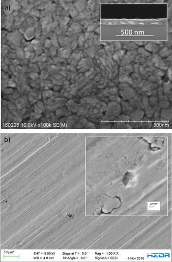
Depending on the specific experiment, different final target properties need to be characterized since they can affect the interaction process, the system evolution and the diagnostic efficiency, for example: thickness, density, geometry, composition, crystalline structure, grain size, surface quality (see Figure 21). Techniques normally used for sample characterization include the following. Scanning electron microscopy (SEM), transmission electron microscopy (TEM), atomic force microscopy (AFM), optical microscopy and optical profilometry are used to characterize the sample geometry, nano and microstructure and surface quality. EDS, X-ray absorption edge spectrometry, Auger electron spectroscopy and CHN combustion analysis allow measurement of the elemental composition. Also X-ray fluorescence (XRF) is normally used for elemental and chemical analysis. Raman spectroscopy and infrared spectroscopy (dispersive or Fourier transformed, FTIR) measure vibrational modes in the sample allowing for characterization of chemical bonds. Areal density can be measured by EDS, optical and X-ray reflectometry, XRF with thickness standards, X-ray absorption edge spectrometer. Optical reflectometry and ellipsometry can be used to measure the material dispersion relation and film thickness. Thickness can be also measured by cross-section SEM analysis and confocal optical microscopy. FIB, cryogenic ion beam polishing and cutting are also used to prepare samples for further bulk analysis. The crystallographic phases and textures of a sample is measured by XRD. Electron backscatter diffraction (EBSD) is used for grain orientation, texture mapping, and measuring dislocation density. Other techniques include: precision micro-balance (resolution about $0.1~\unicode[STIX]{x03BC}\text{g}$
) for mass and density; X-ray micro tomography; thermogravimetric analysis; micro-hardness tests, residual gas analysis for gas fill compositions; nitrogen absorption analysis for surface area, pore size, and skeleton density measurement; porosimetry for pore size; contact X-ray radiography.
$0.1~\unicode[STIX]{x03BC}\text{g}$
) for mass and density; X-ray micro tomography; thermogravimetric analysis; micro-hardness tests, residual gas analysis for gas fill compositions; nitrogen absorption analysis for surface area, pore size, and skeleton density measurement; porosimetry for pore size; contact X-ray radiography.
Ideally, experimentalists would like to know as much as possible about the properties of each target in order to correlate them with experimental results for each shot. However, most of these techniques are time consuming and this approach is not realistic for large numbers of targets for high repetition rate experiments, unless completely automated characterization processes are developed. In this frame, the most adequate approach is to characterize the production process, rather than each target, and ensure process reproducibility. Therefore, only a few targets from each batch of nominally identical samples has to be characterized to assess the variability of target properties. This information can be used to correlate statistical fluctuations in experimental observations with target property variations and understand what shot-to-shot variation is to be expected due to target variations.
Another critical issue is whether online target characterization is possible and preferable to off-line characterization. The latter is in general more accurate. However, online characterization would allow characterization of the actual properties of the object to be irradiated just before the shot, and to check if any damage has occurred due to the irradiation of neighbouring targets (see Section 4). Online characterization might be too slow for high repetition rate experiments, interfere with experimental diagnostic access or be limited by the compatibility of instruments with the high radiation fluxes and EMPs generated during laser shots. At the moment, online characterization is limited to microscope objectives and Questars (long distance microscopes with resolution in the $1{-}10~\unicode[STIX]{x03BC}\text{m}$
range). Optical reflectometry has been used to measure the thickness of liquid crystal targets[Reference Poole, Willis, Cochran, Hanna, Andereck and Schumacher70].
$1{-}10~\unicode[STIX]{x03BC}\text{m}$
range). Optical reflectometry has been used to measure the thickness of liquid crystal targets[Reference Poole, Willis, Cochran, Hanna, Andereck and Schumacher70].
Computer vision and force sensing have been added to the fixture-based robotic planar target assembly station. Unpublished from N. Alexander and P. Fitzsimmons (GA-ICF).
Two key issues are related to the demand for large numbers of targets: how to scale production processes to large numbers of targets and how to ensure the reproducibility of target properties. Automated systems for target production, characterization and assembly are probably the only viable solution for both issues. Advantages of automation are high speed assembly over long times, and reproducibility of assembly and handling of delicate parts over long runs that is superior to manual effort (i.e., reduced operator fatigue). Mass production is possible in a few specialized laboratories for micromachining (with integrated confocal microscopy), coating techniques and replication of micromachined surfaces (by using cast replicas as mandrels for plating or by thermal embossing). General Atomics has developed robotic capability for target assembly by using commercial robotic arms augmented with precision X–Y and in some cases Z translation stages used as build platforms. Jigs must be built for each distinct experiment, and assembly steps programmed, therefore considerable initial setup effort is required for each type of assembly. However, incorporation of visual and force feedback to measure the location of randomly placed parts, and development of general purpose jigs and code modules have reduced setup time considerably and the robotic assembling system is now used even for assembly runs of a few hundreds of targets (see Figure 22). Also the CLF Target Fabrication Group makes use of jigs to assemble up to 100–200 targets per experiment.
As regards characterization, automation done to date has typically been restricted to single measurements of carefully organized batches. In general, some characterization methods are more amenable to automation than others. For instance, automated dimensional inspection is commercially available in optical coordinate measurement machines (OCMM). Techniques with large standoff distances and atmospheric pressure operating conditions such as optical reflectometry can be automated with pick and place of targets or rastering of targets on palettes. Some systems that require precision adjustment of the instrument to the target have been demonstrated using robotic arms (e.g., automated AFM)[Reference Carlson, Huang, Alexander, Bousquet, Farrell and Nikroo132]. Methods that require vacuum conditions, such as SEM will require more effort. Techniques that require extensive sample preparation, such as TEM, may not be appropriate for automation. We imagine that a facility capable of handling the targets for an upcoming campaign (probably ${>}10^{3}$
) would have the capability to automatically hand-off targets from one device to the next, be sufficiently flexible to allow a variety of measurement sequences, and track the resulting measurement for each target.
${>}10^{3}$
) would have the capability to automatically hand-off targets from one device to the next, be sufficiently flexible to allow a variety of measurement sequences, and track the resulting measurement for each target.
Robotics expertise is not widely available, nor is its current level of flexibility in setup appreciated in the community. A conscious effort will be needed to provide adequate assembly capability by the time high repetition rate facilities get to full operation (2018–2020). It is also reasonable to expect that operations will emphasize simpler targets and smaller numbers for some time, as operators and experimentalist get used to the opportunities offered by the new capabilities.
4 High repetition rate challenges
As discussed in Section 2, high repetition rate operation would be beneficial for high-power laser experiments in order to have better statistics (shot-to-shot variations introduce large uncertainties), to investigate complex effects such as plasma instabilities, to build up signal for X-ray diagnostics and for the production of laser-driven radiation and particle sources.
Currently, high-intensity CPA Ti:sapphire laser systems can run at 10 Hz, with perspective of technological improvement based, for example on fibre technologies that could lead to kHz repetition rates[Reference Mourou, Brocklesby, Tajima and Limpert133]. Thus, the repetition rate limitations are not machine related but rather due to a number of issues related to the interaction of laser pulses with solid targets at 0.1–10 Hz. Some of these issues are specifically related to operation in repetitive regime, others are present for shot-on-demand experiments but are expected to be considerably worsened in the high repetition rate regime. An open question is the existence of problems uniquely related to high repetition rates due to some kind of equilibrium state in which each shot is affected by the previous shot.
In this section, we briefly discuss the main issues related to high repetition rate operation, such as: protection from target debris and neighbouring target damage (Section 4.1); fast target refreshing, positioning and alignment (Section 4.2); EMPs, (Section 4.3), and other problems including backreflection and activation of the interaction area due to secondary radiation (Section 4.4). The relevance of these issues depends strongly on the experimental configuration (laser parameters, target properties, repetition rate), therefore the development of a toolkit of solutions to be deployed as needed is more appropriate than a single universal solution. The parameter space is very broad and the physical phenomena involved are in some cases extremely complex. Therefore, extensive parametric investigations would be needed to scale existing solutions at higher repetition rates.
4.1 Protection from debris and neighbouring target damage
The production of debris in the laser–matter interaction and the possibility of damage in neighbouring targets are among the most severe problems hindering high repetition rate experiments. High-intensity or high-energy laser pulses normally vaporize several $\unicode[STIX]{x03BC}\text{g}$
to mg of the target material within hundreds of
$\unicode[STIX]{x03BC}\text{g}$
to mg of the target material within hundreds of $\unicode[STIX]{x03BC}\text{m}$
of the focal spot, create high kinetic energy shrapnel from a considerable region outside of that, and send a considerable shock through the surviving structure. This gives rise to multiple side effects: nonshielded optics can be coated by the vaporized material or damaged by shrapnel and targets cm away from the focal spot can be damaged by the shock wave. Therefore, the two main concerns related to target debris are the protection of optics and components in the interaction chamber and the preservation of neighbouring (nonirradiated) targets. The relevance of these issues is strongly dependent on laser parameters (i.e., high-energy long pulse lasers create more debris than high-intensity short pulse lasers) and on target composition and size, but scaling laws are currently not available.
$\unicode[STIX]{x03BC}\text{m}$
of the focal spot, create high kinetic energy shrapnel from a considerable region outside of that, and send a considerable shock through the surviving structure. This gives rise to multiple side effects: nonshielded optics can be coated by the vaporized material or damaged by shrapnel and targets cm away from the focal spot can be damaged by the shock wave. Therefore, the two main concerns related to target debris are the protection of optics and components in the interaction chamber and the preservation of neighbouring (nonirradiated) targets. The relevance of these issues is strongly dependent on laser parameters (i.e., high-energy long pulse lasers create more debris than high-intensity short pulse lasers) and on target composition and size, but scaling laws are currently not available.
Target damage observed for a sheet of Ti $2~\unicode[STIX]{x03BC}\text{m}$
thick with carbon foam coating: (a) target sheet clamped between two identical protective grids before the experiment, (b) damage observed in the target sheet while dismantling the target after the experiment.
$2~\unicode[STIX]{x03BC}\text{m}$
thick with carbon foam coating: (a) target sheet clamped between two identical protective grids before the experiment, (b) damage observed in the target sheet while dismantling the target after the experiment.

For planar targets designed as a continuous sheet of material allowing multiple shots, neighbouring target damage can be due to material vaporization (millimetres away from the interaction region), shock waves or even heat waves propagating in the sample for centimetres. Therefore, target holders should be designed to avoid redeposition of evaporated material: the upcoming targets in the target holder must be protected from the vapour and heat generated by shots on the preceding targets and isolated from each other. It is also necessary to prevent the laser beam from directly interacting with the target holder. Laser burn has often been observed on target holders up to 1 cm from the focal spot; the extent of those marks had been put down to imperfect laser focus. The intensity in a perfectly focused laser beam (an Airy disc) decreases as a power law $I(x)\propto (2J_{1}(x)/x)^{2}$
, where
$I(x)\propto (2J_{1}(x)/x)^{2}$
, where $x$
is the distance from the centre) rather than the widely assumed Gaussian
$x$
is the distance from the centre) rather than the widely assumed Gaussian $I(x)\propto e^{-x^{2}}$
. The slower decrease puts significant laser energy at surprisingly large radii. A rule of thumb is that material is vaporized (and a shock generated) for
$I(x)\propto e^{-x^{2}}$
. The slower decrease puts significant laser energy at surprisingly large radii. A rule of thumb is that material is vaporized (and a shock generated) for $I>10^{11}~\text{W}/\text{cm}^{2}$
. When dealing with an intensity at the focus of
$I>10^{11}~\text{W}/\text{cm}^{2}$
. When dealing with an intensity at the focus of $10^{21}~\text{W}/\text{cm}^{2}$
, for instance, one is concerned with the wings of the focused beam out to
$10^{21}~\text{W}/\text{cm}^{2}$
, for instance, one is concerned with the wings of the focused beam out to $I(r)/I_{0}$ ${\approx}10^{-10}$
, which occurs at about 1000 times the radius of half intensity of the focused beam or a few mm from the focus[Reference Hecht and Zajac134]. And that is the best possible condition; imperfections in the laser pulse wave front will make the problem worse. So it would be necessary to clip those laser focus wings with a near-field 1 mm diameter aperture (about 1 mm distant from the focus), to clip the beam at an intensity about
${\approx}10^{-10}$
, which occurs at about 1000 times the radius of half intensity of the focused beam or a few mm from the focus[Reference Hecht and Zajac134]. And that is the best possible condition; imperfections in the laser pulse wave front will make the problem worse. So it would be necessary to clip those laser focus wings with a near-field 1 mm diameter aperture (about 1 mm distant from the focus), to clip the beam at an intensity about $10^{-9}I_{0}$
. The interference perturbations that the edge will generate should be insignificant compared to the intensity in the focused spot. Using a truncated re-entrant cone for the aperture would limit the interference of this device with other beams, and minimize the material vaporized off the iris surface (intensity reduced by cosine function).
$10^{-9}I_{0}$
. The interference perturbations that the edge will generate should be insignificant compared to the intensity in the focused spot. Using a truncated re-entrant cone for the aperture would limit the interference of this device with other beams, and minimize the material vaporized off the iris surface (intensity reduced by cosine function).
A possible solution is to separate single shots by a suitable distance, but this is not an option if targets are to be mounted as a single sheet: a 60 cm large sheet of target material would be needed for $3600$
shots with 1 cm spacing between neighbouring targets, i.e., for 1 h operation at 1 Hz. Another possibility is to clamp the target sheet between two grids, even though this solution can be sometimes ineffective for targets produced on a single wafer or for fragile micro and nanostructures. In Figure 23 an example of an irradiated target sheet is reported (Ti foil
$3600$
shots with 1 cm spacing between neighbouring targets, i.e., for 1 h operation at 1 Hz. Another possibility is to clamp the target sheet between two grids, even though this solution can be sometimes ineffective for targets produced on a single wafer or for fragile micro and nanostructures. In Figure 23 an example of an irradiated target sheet is reported (Ti foil $2~\unicode[STIX]{x03BC}\text{m}$
thick, with carbon foam coating). The sheet was clamped between two identical frames as shown in Figure 23(a). Figure 23(b) shows holes in the Ti foil where the foil had been irradiated and damage in the nanostructured coating for the first (and second) neighbours, while the metallic foil was intact. These observations have been confirmed by SEM analysis: only traces of the carbon foam coating survive in a radius of 5 mm. This effect had not been observed in previous experiments, in which a different holder geometry was used (thicker frame with conical holes at larger distance)[Reference Prencipe, Sgattoni, Dellasega, Fedeli, Cialfi, Woo Choi, Jong Kim, Janulewicz, Kakolee, Lee, Sung, Lee, Nam and Passoni83]. In general, alternative approaches are needed to sufficiently isolate and protect one target from another, while allowing a very large number of targets to be automatically inserted. In addition, online characterization would be needed to avoid shooting damaged targets, which could make data interpretation hard and compromise the whole experimental campaign. Online characterization should be fast and automatized and instrumentation should be resistent to X-rays and EMP.
$2~\unicode[STIX]{x03BC}\text{m}$
thick, with carbon foam coating). The sheet was clamped between two identical frames as shown in Figure 23(a). Figure 23(b) shows holes in the Ti foil where the foil had been irradiated and damage in the nanostructured coating for the first (and second) neighbours, while the metallic foil was intact. These observations have been confirmed by SEM analysis: only traces of the carbon foam coating survive in a radius of 5 mm. This effect had not been observed in previous experiments, in which a different holder geometry was used (thicker frame with conical holes at larger distance)[Reference Prencipe, Sgattoni, Dellasega, Fedeli, Cialfi, Woo Choi, Jong Kim, Janulewicz, Kakolee, Lee, Sung, Lee, Nam and Passoni83]. In general, alternative approaches are needed to sufficiently isolate and protect one target from another, while allowing a very large number of targets to be automatically inserted. In addition, online characterization would be needed to avoid shooting damaged targets, which could make data interpretation hard and compromise the whole experimental campaign. Online characterization should be fast and automatized and instrumentation should be resistent to X-rays and EMP.
Targets mounted on thin foils. (a) $250~\unicode[STIX]{x03BC}\text{m}$
diameter,
$250~\unicode[STIX]{x03BC}\text{m}$
diameter, $80~\unicode[STIX]{x03BC}\text{m}$
thick aluminium disk glued to 30 nm CH foil; (b) WYKO plot of
$80~\unicode[STIX]{x03BC}\text{m}$
thick aluminium disk glued to 30 nm CH foil; (b) WYKO plot of $50~\unicode[STIX]{x03BC}\text{m}$
diameter,
$50~\unicode[STIX]{x03BC}\text{m}$
diameter, $1.3~\unicode[STIX]{x03BC}\text{m}$
copper disk deposited on 30 nm CH film, from R. B. Stephens and N. Alexander (GA-IFT).
$1.3~\unicode[STIX]{x03BC}\text{m}$
copper disk deposited on 30 nm CH film, from R. B. Stephens and N. Alexander (GA-IFT).

In addition, the evaporated material and shrapnel impacting the whole chamber is detrimental to all exposed surfaces, including delicate and expensive components such as optics and diagnostics. Therefore, solutions to mitigate component damage need to be implemented. This issue is relevant also in shot-on-demand experiments, but in this case the vaporization rate is low enough and the off-axis parabola is usually protected with disposable debris shields, to be replaced when damaged or when their transmission is no longer optimal. Currently available debris shields will not be a viable solution for high repetition rate experiments: the degradation rate will be orders of magnitude higher and debris shields will need to be replaced much more often resulting in a waste of time and in increased operation costs, as debris shields can be large and expensive for advanced laser facilities, for example: 550 mm for the 10 PW laser system at ELI-NP, 400 mm for Apollon. The development of cheap and automatic replacement systems for debris collectors and shields is needed. An example is a membrane tape to be rolled progressively as it gets coated, but this solution is not resistant to shrapnel impact: chunks of material accelerated towards the membrane would most likely tear it apart.
Other solutions have been proposed for debris shielding. For example, while plasma is globally neutral, debris could be polarized. Therefore, debris could be collected by polarizing shrapnel and vaporized material and applying an electric field. This technique has been proposed for low energy laser pulses[Reference Park and Farson135] and it would need further development and testing for application in high-power laser experiments. Another possibility is to use disposable or regenerable intermediate optics, or to move the second plasma mirror into the interaction chamber. Liquid metal mirrors have been investigated as robust plasma facing mirrors for EUV lithography sources[Reference Fahy, O’Reilly, Scally and Sheridan136] and are in use for astronomical telescopes[Reference Hickson, Pfrommer, Cabanac, Crotts, Johnson, de Lapparent, Lanzetta, Gromoll, Mulrooney, Sivanandam and Truax137]. Grazing incidence liquid metal mirrors (GILMM) could be adopted as regenerable mirrors. GILMM are thin films of liquid metal (Hg, Ga, Li or Na) spun over a polished support allowing for rapid refreshing of the reflective surface[Reference Moir138]. Disposable parabolas with lower price and quality could be used, but this solution would result in a decrease of the pulse intensity (of a factor 10). Liquid crystal films have been recently proposed as debris shields or plasma mirrors in the interaction chamber. Debris shields could also be part of the sample holder, or integrated in the sample design: every sample could be surrounded by a disposable debris shield with appropriate openings to guarantee access for optical laser and diagnostics.
In general, the shock, shrapnel, and debris can be minimized by shrinking the actual target to an area that will be surely vaporized and supporting it with ultrathin films, thin micromachined structures or high stiffness fibres. This would also ease chamber cleaning procedures and any health hazards associated to nano-dispersions. Figure 24 shows an example of reduced mass target supported by an ultrathin CH layer. In general, $300~\unicode[STIX]{x03BC}\text{m}$
diameter is sufficient for most types of targets and target thickness rarely needs to exceed
$300~\unicode[STIX]{x03BC}\text{m}$
diameter is sufficient for most types of targets and target thickness rarely needs to exceed $100~\unicode[STIX]{x03BC}\text{m}$
(or a few hundreds of
$100~\unicode[STIX]{x03BC}\text{m}$
(or a few hundreds of $\unicode[STIX]{x03BC}\text{m}$
): using targets with these dimensions would reduce debris by a factor 100. The thin support for reduced mass targets would need to be mechanically stable and their vibration amplitude should be within the precision required for positioning the target in the laser focus. Carbon fibres or membranes would also limit shock propagation to nearby targets, hence reducing first neighbour damage, even though target isolation would still be necessary. A separation of about 5 mm between two reduced mass targets should be adequate for most experiments.
$\unicode[STIX]{x03BC}\text{m}$
): using targets with these dimensions would reduce debris by a factor 100. The thin support for reduced mass targets would need to be mechanically stable and their vibration amplitude should be within the precision required for positioning the target in the laser focus. Carbon fibres or membranes would also limit shock propagation to nearby targets, hence reducing first neighbour damage, even though target isolation would still be necessary. A separation of about 5 mm between two reduced mass targets should be adequate for most experiments.
4.2 Target positioning and alignment
In general, target handling devices should be designed to take into account issues, such as: accessibility for diagnostics, first neighbour damage, redeposition of evaporated material, target and holder damage from unfocused laser radiation, X-rays, EMP effects and holder activation. In addition, a crucial requirement for high repetition rate experiments is that the sample must be positioned with $\unicode[STIX]{x03BC}\text{m}$
precision longitudinal and possibly transverse directions at the right time (every 100 ms for 1 Hz). Targets need to be rastered rapidly and steadily in the focal plane, and standard procedures for quick alignment should be available. User facility positioning systems must be flexible enough to accommodate very different kinds of targets, possibly while allowing for target characterization. The upcoming targets in the target holder must be protected from the vapour and heat generated by shots on the preceding targets. For efficient operation, several hours of targets (about
$\unicode[STIX]{x03BC}\text{m}$
precision longitudinal and possibly transverse directions at the right time (every 100 ms for 1 Hz). Targets need to be rastered rapidly and steadily in the focal plane, and standard procedures for quick alignment should be available. User facility positioning systems must be flexible enough to accommodate very different kinds of targets, possibly while allowing for target characterization. The upcoming targets in the target holder must be protected from the vapour and heat generated by shots on the preceding targets. For efficient operation, several hours of targets (about $10^{4}$
) must be loaded in the target chamber on each pump down and the last target shot must be as clean as the first. That will require a vapour shield around the target holder to prevent vapour re-condensation. Moreover, 10 Hz operation of even a 1 J laser delivers 10 W into the heart of a vacuum system (and a 100 J laser would deliver 1 kW). The targets – in vacuum and mounted on thin foils – have no way to dissipate heat and the resulting local temperature increases will very likely have consequences for dimensional stability as well as operation of components, and might affect the condition of the target. Therefore, the shroud that protects them from vapour must be actively cooled to prevent them overheating, even though an actively cooled shroud would complicate the problem of auto-exchange of target arrays. The idea would be to use mechanical isolation of the target holder from its targets, and optical shielding of the holder from the laser to prevent shocks in the holder that could damage upcoming targets. Proper design of a target handler that accurately places targets, protects upcoming ones, has sufficient capacity to operate for a few hours before refilling, and causes minimal interference with beams and diagnostics, is a substantial engineering job.
$10^{4}$
) must be loaded in the target chamber on each pump down and the last target shot must be as clean as the first. That will require a vapour shield around the target holder to prevent vapour re-condensation. Moreover, 10 Hz operation of even a 1 J laser delivers 10 W into the heart of a vacuum system (and a 100 J laser would deliver 1 kW). The targets – in vacuum and mounted on thin foils – have no way to dissipate heat and the resulting local temperature increases will very likely have consequences for dimensional stability as well as operation of components, and might affect the condition of the target. Therefore, the shroud that protects them from vapour must be actively cooled to prevent them overheating, even though an actively cooled shroud would complicate the problem of auto-exchange of target arrays. The idea would be to use mechanical isolation of the target holder from its targets, and optical shielding of the holder from the laser to prevent shocks in the holder that could damage upcoming targets. Proper design of a target handler that accurately places targets, protects upcoming ones, has sufficient capacity to operate for a few hours before refilling, and causes minimal interference with beams and diagnostics, is a substantial engineering job.
Hereinafter, a few possible concepts for target positioning systems are illustrated. Several options are being considered, including: planar target holders, tape targets, and targets carried on strips and belts.
Planar target delivery systems allow positioning of targets by rastering or rotating a holder containing arrays of samples. This geometry is optimal when the targets are produced as a continuous sheet of material, such as a thin foil or a wafer. Fiducial marks are often used to measure the exact position of the holder and adjust it with micrometre precision. This type of delivery system often allows the mounting of a target holder (specifically designed for a type of target) in a standard frame usually connected to stepper motors.
The High Repetition Rate Sample Delivery (HIREP) working package of the European Cluster of Advanced Laser Light Sources (EUCALL) is developing an integrated concept for decentralized sample characterization and fast sample replacement. The system is composed of a flat carrier frame (specific to each partner facility) and an inner target frame common for all partner facilities (including the ELI pillars, European XFEL, HZDR, Max IV, Desy)[139]. The target frame is made of Ti or Al and has a rectangular shape ( $140~\text{mm}\times 130~\text{mm}$
) with maximum thickness of 6 mm. The inner part of each target frame will be tailored for each experiment, either designed by the users or chosen among a set of available geometries. The external part will have a standard geometry to allow for mounting in the carrier frame and placement of fiducial marks and an identification mark. Targets will be characterized before the experiment. Target coordinates with respect to fiducials will be measured (using an automatic sample screening software), stored in a database and uploaded during the beamtime so that targets can be positioned in the focal spot by rastering the frame. A similar concept has been developed for the interaction area of the ELIMAIA beamline (ELI Multidisciplinary Applications of laser-Ion Acceleration, ELI-Beamlines). The ELIMAIA target tower (shown in Figure 25) offers 5 degrees of freedom, with
$140~\text{mm}\times 130~\text{mm}$
) with maximum thickness of 6 mm. The inner part of each target frame will be tailored for each experiment, either designed by the users or chosen among a set of available geometries. The external part will have a standard geometry to allow for mounting in the carrier frame and placement of fiducial marks and an identification mark. Targets will be characterized before the experiment. Target coordinates with respect to fiducials will be measured (using an automatic sample screening software), stored in a database and uploaded during the beamtime so that targets can be positioned in the focal spot by rastering the frame. A similar concept has been developed for the interaction area of the ELIMAIA beamline (ELI Multidisciplinary Applications of laser-Ion Acceleration, ELI-Beamlines). The ELIMAIA target tower (shown in Figure 25) offers 5 degrees of freedom, with $1.5~\unicode[STIX]{x03BC}\text{m}$
resolution for the degree of freedom used in focusing (along the laser axis). In its first version, conceived largely for testing purposes, it allowed loading 900 targets, but has been designed to readily scale up to several times that number of targets without inherently reduced accuracy. From a purely target positioning performance standpoint (i.e., independent of performance of targets themselves) it is currently able to perform at 10 Hz. However, how well accuracy is maintained at higher rates does remain to be verified. The structure has been designed to remain stable and free of oscillation at higher speeds, also with the support of finite element analysis.
$1.5~\unicode[STIX]{x03BC}\text{m}$
resolution for the degree of freedom used in focusing (along the laser axis). In its first version, conceived largely for testing purposes, it allowed loading 900 targets, but has been designed to readily scale up to several times that number of targets without inherently reduced accuracy. From a purely target positioning performance standpoint (i.e., independent of performance of targets themselves) it is currently able to perform at 10 Hz. However, how well accuracy is maintained at higher rates does remain to be verified. The structure has been designed to remain stable and free of oscillation at higher speeds, also with the support of finite element analysis.
Fast target positioning system developed for the ELIMAIA interaction area, ELI-Beams. From T. Wiste.
In general, a possible concern with the flat carrier target scheme, with open area of 10–20 cm is that the density of targets in the carrier is limited to hundreds for full energy shots. At 10 Hz, each carrier is exhausted in about a few minutes.
The High Accuracy Microtarget Supply (HAMS) is a 7 axis target supply system that is being developed by the Central Laser Facility and Scitech Precision Ltd for use on beamlines[Reference Booth, Clarke, Heathcote, Neely, Pattathil, Rusby, Spindloe, Symes, Tolley and Tomlinson140, Reference Symes, Booth, Baraclough, Indorf, Oliver, Scott, Neely, Spindloe, Heathcote, Clarke, Foster, Gregory and Rajeev141]. It is being tested on the Gemini laser system with an F2 beam and is specified to have a positioning accuracy in the laser propagation direction of 4 and $10~\unicode[STIX]{x03BC}\text{m}$
in the transverse plane. The goal is to refresh targets every 40 s, in order to fully exploit the maximum repetition rate of the laser system (25 mHz). The project is using high specification stages, high precision encoders, bespoke target interface supports, interferometric positioning and software control to be able to accurately position targets within a window of
$10~\unicode[STIX]{x03BC}\text{m}$
in the transverse plane. The goal is to refresh targets every 40 s, in order to fully exploit the maximum repetition rate of the laser system (25 mHz). The project is using high specification stages, high precision encoders, bespoke target interface supports, interferometric positioning and software control to be able to accurately position targets within a window of $100~\unicode[STIX]{x03BC}\text{m}$
to the laser focus. A wheel acts as an interface between the positioning system and target arrays. The wheel flatness is within a few
$100~\unicode[STIX]{x03BC}\text{m}$
to the laser focus. A wheel acts as an interface between the positioning system and target arrays. The wheel flatness is within a few $\unicode[STIX]{x03BC}\text{m}$
over the wheel area in order to have mounting accuracy within
$\unicode[STIX]{x03BC}\text{m}$
over the wheel area in order to have mounting accuracy within $2~\unicode[STIX]{x03BC}\text{m}$
. This system is used for wafer-based targets: 8 wafer sectors (688 targets) can be mounted with no needs for assembly. Debris mitigation techniques allow positioning of targets every few mm therefore utilizing as much of the available target area as possible. The system is modular and so the stages can be deployed on any beamline with only a small modification the top mount. In general, the disadvantage of rotational positioning systems with respect to translational designs is that larger number of targets result in larger distances between targets and the centre of motion potentially introducing reduced accuracy. However, this effect has been compensated for in the CLF design.
$2~\unicode[STIX]{x03BC}\text{m}$
. This system is used for wafer-based targets: 8 wafer sectors (688 targets) can be mounted with no needs for assembly. Debris mitigation techniques allow positioning of targets every few mm therefore utilizing as much of the available target area as possible. The system is modular and so the stages can be deployed on any beamline with only a small modification the top mount. In general, the disadvantage of rotational positioning systems with respect to translational designs is that larger number of targets result in larger distances between targets and the centre of motion potentially introducing reduced accuracy. However, this effect has been compensated for in the CLF design.
A completely different geometry is based on 1D arrays of targets (scaled up target ladders) for auto-exchanging and limiting the intrusion of the protective shroud. One can store about 1000 ladders, each containing about 200 targets in a cylindrical cassette 40 cm diameter by 100 cm long. Rotation of the cassette puts a selected ladder on a frame that is pulled out by a motorized arm. Only the un-shot targets must be shielded, allowing better diagnostic access than possible with planar arrays. Short-range piezo-motors can position the ladder at laser focus. There is a short interruption in the shots after a ladder is completed when the arm drops the empty ladder and reaches to fetch a new one. Figure 26 shows a concept model of a ladder positioning system.
Concept model of a ladder positioning system, composed of: a ladder supply cassette loaded with new targets; a motorized arm to pull out ladders from the cassette; precision motors to place the target at laser focus; a drop-off cassette receiving used ladders. From N. Alexander (GA-IFT).
Target fielding system concept, utilizing mechanism of cinema film projector, mounts targets on carbon fibres over holes in linked belts or continuous steel film strips (not shown). Target quantities in excess of $10^{4}$
can be placed on manageable sized reels. From N. Alexander (GA-IFT).
$10^{4}$
can be placed on manageable sized reels. From N. Alexander (GA-IFT).
General Atomics is developing a high repetition target fielding scheme based on mechanisms in a cinema film projector (shown in Figure 27). Film projectors operate at a frame rate of 24 Hz, which is consistent with the laser facilities being discussed here. Targets are mounted to a continuous steel film strip or linked belt that is wound up into a reel for fielding. Targets are suspended on a pair of $\unicode[STIX]{x03BC}\text{m}$
diameter fibres over holes in the film strip. Position fiducials (embossed micro-corner cubes or apertures) allow target position to be measured ex-chamber with respect to the fiducials and in-chamber located using lasers and remote located (metres) sensors. The position stability of targets mounted in this manner and subject to levels of vibration has been demonstrated, as well as position repeatability in locating, at the micron level, the target carrier utilizing detection of the Poisson spot produced through laser illumination of aperture fiducials from metre distances[Reference Alexander, Goodin and Stephens142]. The Geneva drive mechanism in projectors provides for the film strip to be clamped firmly to positioning stages for approximately 75% of the frame rate period time; film advancing occurring during the remaining 25% of time. During this clamped time, the target position can be measured and adjusted by the positioning stages. The flexibility of the film or linked belts allows upcoming targets to be shot to be positioned behind shields to protect them from debris of prior target shots. The fibre mounting limits shock from prior shots impacting nearby targets. Protrusions are commonly fabricated onto steel film strips[143], these can be used to space the strip from itself as it is wound onto a reel, thereby protecting targets from being knocked off. A reel of inner and outer diameters of 10 and 40 cm, with a 1 mm winding spacing, and targets placed at 1 cm intervals can accommodate over
$\unicode[STIX]{x03BC}\text{m}$
diameter fibres over holes in the film strip. Position fiducials (embossed micro-corner cubes or apertures) allow target position to be measured ex-chamber with respect to the fiducials and in-chamber located using lasers and remote located (metres) sensors. The position stability of targets mounted in this manner and subject to levels of vibration has been demonstrated, as well as position repeatability in locating, at the micron level, the target carrier utilizing detection of the Poisson spot produced through laser illumination of aperture fiducials from metre distances[Reference Alexander, Goodin and Stephens142]. The Geneva drive mechanism in projectors provides for the film strip to be clamped firmly to positioning stages for approximately 75% of the frame rate period time; film advancing occurring during the remaining 25% of time. During this clamped time, the target position can be measured and adjusted by the positioning stages. The flexibility of the film or linked belts allows upcoming targets to be shot to be positioned behind shields to protect them from debris of prior target shots. The fibre mounting limits shock from prior shots impacting nearby targets. Protrusions are commonly fabricated onto steel film strips[143], these can be used to space the strip from itself as it is wound onto a reel, thereby protecting targets from being knocked off. A reel of inner and outer diameters of 10 and 40 cm, with a 1 mm winding spacing, and targets placed at 1 cm intervals can accommodate over $1.17\times 10^{4}$
targets; over 3 h of operation at 1 Hz. This scheme is a virtually continuous analogue to the ladder target fielding scheme.
$1.17\times 10^{4}$
targets; over 3 h of operation at 1 Hz. This scheme is a virtually continuous analogue to the ladder target fielding scheme.
Finally, thin foils which are robust enough to be wound onto a reel can be positioned by tape drive target delivery systems. The working principle of tape drive systems is quite simple: the target is positioned in the laser focus by spooling the tape. Repetition rates up to 1 kHz have been demonstrated[Reference Haney, Berger, Kubiak, Rockett and Hunter144].
4.3 EMPs
The generation of EMPs is a consequence of the interaction of high-power laser pulses with solid matter and can produce severe problems for electronic devices located in the experimental room. The EMP impinging on electronic devices generates oscillating currents in the electronic components and can damage the internal circuits of electronic devices. The coupling of EMP radiation with electronic devices in the experimental room interferes with the correct operation of the devices, producing additional noise in detector readouts and disturbing motor operation. The electronic systems themselves can become an important source of EMP[Reference Brown, Bond, Clancy, Dangi, Eder, Ferguson, Kimbrough and Throop145, Reference Brown, Ayers, Felker, Ferguson, Holder, Nagel, Piston, Simanovskaia, Throop, Chung and Hilsabeck146]. A number of dedicated studies have been devoted to EMP investigation, in order to minimize these collateral effects[Reference Brown, Bond, Clancy, Dangi, Eder, Ferguson, Kimbrough and Throop145, Reference Brown, Ayers, Felker, Ferguson, Holder, Nagel, Piston, Simanovskaia, Throop, Chung and Hilsabeck146]. In addition, unwanted currents can be generated by ionization due to X-ray and energetic particles impinging on electronic devices and cables[Reference Barbarino and Consoli147, Reference Consoli, De Angelis, Andreoli, Cristofari and Di Giorgio148].
EMP are generated as a consequence of the propagation of laser-generated relativistic electrons and return currents that balance the resulting space charge distribution[Reference Mora149]. Pulsed return currents flowing from target to ground due to target polarization have duration up to $1~\unicode[STIX]{x03BC}\text{s}$
, amplitude up to tens of kA and frequency ranging from few MHz to hundreds of GHz[Reference Benjamin, McCall and Ehler150–Reference Cikhardt, Krása, De Marco, Pfeifer, Velyhan, Krouský, Cikhardtová, Klír, Řezáč, Ullschmied, Skála, Kubeš and Kravárik152]. The laser-driven hot-electron current and the return current flowing from the target to the ground produce EMP[Reference Felber153] lasting up to
$1~\unicode[STIX]{x03BC}\text{s}$
, amplitude up to tens of kA and frequency ranging from few MHz to hundreds of GHz[Reference Benjamin, McCall and Ehler150–Reference Cikhardt, Krása, De Marco, Pfeifer, Velyhan, Krouský, Cikhardtová, Klír, Řezáč, Ullschmied, Skála, Kubeš and Kravárik152]. The laser-driven hot-electron current and the return current flowing from the target to the ground produce EMP[Reference Felber153] lasting up to $1~\unicode[STIX]{x03BC}\text{s}$
, with peak to peak amplitude up to hundreds of kV and with frequency ranging from MHz to hundreds of GHz[Reference Barbarino and Consoli147, Reference Consoli, De Angelis, Andreoli, Cristofari and Di Giorgio148, Reference Krása, Cikhardt, De Marco, Klír, Velyhan, Rezac, Pfeifer, Krousky, Skala, Dudzak, Dostal, Kaufman, Ullschmied and Limpouch154–Reference Poyé, Hulin, Bailly-Grandvaux, Dubois, Ribolzi, Raffestin, Bardon, Lubrano-Lavaderci, d’Humiéres, Santos, Nicolaï and Tikhonchuk157]. EMP characteristics are strictly connected with the number and energy of electrons emitted during laser–target interaction. A model developed by Poyé et al.
[Reference Poyé, Dubois, Lubrano-Lavaderci, Raffestin, Ribolzi, Gazave, La Fontaine, d’Humières, Hulin, Nicolaï and Tikhonchuk158] allows correlation of laser pulse parameters (laser pulse energy, duration and focal spot size) with EMP emission. Three different laser–matter interaction regimes are considered by this model: (i) quasi-instantaneous ejection regime – the laser pulse is so short that all hot electrons generated in the interaction are ejected from the target almost instantly; (ii) intermediate regime – for longer laser pulses, a fraction of the hot electrons is trapped by the target potential, the dynamics of electrons in the target leads to EMP production also on timescales longer than the laser pulse duration; (iii) quasi-stationary regime – if the laser pulse duration is long enough an equilibrium is reached between hot-electron production and electron energy dissipation[Reference Poyé, Dubois, Lubrano-Lavaderci, Raffestin, Ribolzi, Gazave, La Fontaine, d’Humières, Hulin, Nicolaï and Tikhonchuk158, Reference Poyé, Dubois, Lubrano-Lavaderci, d’Humières, Bardon, Hulin, Bailly-Grandvaux, Ribolzi, Raffestin, Santos, Nicolaï and Tikhonchuk159]. Electrical properties, geometry and size of the target also have a strong influence on EMP characteristics[Reference Remo, Adams and Jones160]. Once EMP radiation is emitted, the vacuum chamber acts as a resonator. The resonant conditions determine how the signal can evolve in time after the initial radiation[Reference Dubois, Lubrano-Lavaderci, Raffestin, Ribolzi, Gazave, Compant La Fontaine, d’Humiéres, Hulin, Nicolaï, Poyé and Tikhonchuk151, Reference Poyé, Hulin, Bailly-Grandvaux, Dubois, Ribolzi, Raffestin, Bardon, Lubrano-Lavaderci, d’Humiéres, Santos, Nicolaï and Tikhonchuk157, Reference Poyé, Dubois, Lubrano-Lavaderci, Raffestin, Ribolzi, Gazave, La Fontaine, d’Humières, Hulin, Nicolaï and Tikhonchuk158, Reference De Marco, Krása, Cikhardt, Pfeifer, Krouský, Margarone, Ahmed, Borghesi, Kar, Giuffrida, Vrana, Velyhan, Limpouch, Korn, Weber, Velardi, Delle Side, Nassisi and Ullschmied161].
$1~\unicode[STIX]{x03BC}\text{s}$
, with peak to peak amplitude up to hundreds of kV and with frequency ranging from MHz to hundreds of GHz[Reference Barbarino and Consoli147, Reference Consoli, De Angelis, Andreoli, Cristofari and Di Giorgio148, Reference Krása, Cikhardt, De Marco, Klír, Velyhan, Rezac, Pfeifer, Krousky, Skala, Dudzak, Dostal, Kaufman, Ullschmied and Limpouch154–Reference Poyé, Hulin, Bailly-Grandvaux, Dubois, Ribolzi, Raffestin, Bardon, Lubrano-Lavaderci, d’Humiéres, Santos, Nicolaï and Tikhonchuk157]. EMP characteristics are strictly connected with the number and energy of electrons emitted during laser–target interaction. A model developed by Poyé et al.
[Reference Poyé, Dubois, Lubrano-Lavaderci, Raffestin, Ribolzi, Gazave, La Fontaine, d’Humières, Hulin, Nicolaï and Tikhonchuk158] allows correlation of laser pulse parameters (laser pulse energy, duration and focal spot size) with EMP emission. Three different laser–matter interaction regimes are considered by this model: (i) quasi-instantaneous ejection regime – the laser pulse is so short that all hot electrons generated in the interaction are ejected from the target almost instantly; (ii) intermediate regime – for longer laser pulses, a fraction of the hot electrons is trapped by the target potential, the dynamics of electrons in the target leads to EMP production also on timescales longer than the laser pulse duration; (iii) quasi-stationary regime – if the laser pulse duration is long enough an equilibrium is reached between hot-electron production and electron energy dissipation[Reference Poyé, Dubois, Lubrano-Lavaderci, Raffestin, Ribolzi, Gazave, La Fontaine, d’Humières, Hulin, Nicolaï and Tikhonchuk158, Reference Poyé, Dubois, Lubrano-Lavaderci, d’Humières, Bardon, Hulin, Bailly-Grandvaux, Ribolzi, Raffestin, Santos, Nicolaï and Tikhonchuk159]. Electrical properties, geometry and size of the target also have a strong influence on EMP characteristics[Reference Remo, Adams and Jones160]. Once EMP radiation is emitted, the vacuum chamber acts as a resonator. The resonant conditions determine how the signal can evolve in time after the initial radiation[Reference Dubois, Lubrano-Lavaderci, Raffestin, Ribolzi, Gazave, Compant La Fontaine, d’Humiéres, Hulin, Nicolaï, Poyé and Tikhonchuk151, Reference Poyé, Hulin, Bailly-Grandvaux, Dubois, Ribolzi, Raffestin, Bardon, Lubrano-Lavaderci, d’Humiéres, Santos, Nicolaï and Tikhonchuk157, Reference Poyé, Dubois, Lubrano-Lavaderci, Raffestin, Ribolzi, Gazave, La Fontaine, d’Humières, Hulin, Nicolaï and Tikhonchuk158, Reference De Marco, Krása, Cikhardt, Pfeifer, Krouský, Margarone, Ahmed, Borghesi, Kar, Giuffrida, Vrana, Velyhan, Limpouch, Korn, Weber, Velardi, Delle Side, Nassisi and Ullschmied161].
Experimental investigation of EMP requires a collection of current probes to measure currents flowing through the target and of B-Probes and D-Probes to measure magnetic and electric fields in different positions in the vacuum chamber (i.e., at different distances from the target and under different angles)[Reference Consoli, De Angelis, Andreoli, Cristofari and Di Giorgio148, Reference Cikhardt, Krása, De Marco, Pfeifer, Velyhan, Krouský, Cikhardtová, Klír, Řezáč, Ullschmied, Skála, Kubeš and Kravárik152, Reference De Marco, Cikhardt, Krása, Velyhan, Pfeifer, Krouský, Klír, Řezáč, Limpouch, Margarone and Ullschmied156, Reference De Marco, Krása, Cikhardt, Pfeifer, Krouský, Margarone, Ahmed, Borghesi, Kar, Giuffrida, Vrana, Velyhan, Limpouch, Korn, Weber, Velardi, Delle Side, Nassisi and Ullschmied161]. Numerical simulations to calculate resonant frequencies in the vacuum chamber can be used to support the interpretation of experimental results[Reference De Marco, Krása, Cikhardt, Pfeifer, Krouský, Margarone, Ahmed, Borghesi, Kar, Giuffrida, Vrana, Velyhan, Limpouch, Korn, Weber, Velardi, Delle Side, Nassisi and Ullschmied161, 162]. The resonant frequencies as well as the leakage time of EMP energy are directly related with the shape and structure of the chamber[Reference De Marco, Krása, Cikhardt, Pfeifer, Krouský, Margarone, Ahmed, Borghesi, Kar, Giuffrida, Vrana, Velyhan, Limpouch, Korn, Weber, Velardi, Delle Side, Nassisi and Ullschmied161], making evaluation difficult for EMP effects expected of a specific experimental condition using data collected from any other configuration or facility. This is a critical issue because an evaluation of the expected EMP signal when planning a high-power laser experiment is required in order to avoid possible problems for electronic devices, which could even lead to a loss of experimental data[Reference Brown, Bond, Clancy, Dangi, Eder, Ferguson, Kimbrough and Throop145, Reference Brown, Ayers, Felker, Ferguson, Holder, Nagel, Piston, Simanovskaia, Throop, Chung and Hilsabeck146].
Precautions to mitigate collateral effects of EMP include, for example: using shielded cables; shielding electronic devices, even though a complete shielding would be required to insulate a component from the interaction region (not feasible for motors and diagnostics); avoiding the formation of loops in cables and electronic devices, which could act as efficient receiving antennas; using insulating feedthroughs, which is only useful when the unwanted current flow along the cable and electronic devices in the target chamber is lower than the predicted current coming from the vacuum chamber wall; appropriate choice of device positions inside and outside the target chamber in order to minimize exposition to direct radiation[Reference Brown, Bond, Clancy, Dangi, Eder, Ferguson, Kimbrough and Throop145, Reference Brown, Ayers, Felker, Ferguson, Holder, Nagel, Piston, Simanovskaia, Throop, Chung and Hilsabeck146]. At low repetition rates some devices can be powered down before a shot but this is more difficult at 10 Hz.
4.4 Other issues
Secondary radiation produced in the laser–matter interaction can induce nuclear reactions in the interaction chamber and beam dumps. Material activation in the interaction chamber equipment and beam dumps could become a critical issue for high repetition rate facilities. For example, in the ELI-NP case, calculations show that the activation produced by a source term of protons with 500 MeV average energy, driven by the 10 PW laser beam and operated 300 min/day (with repetition rate of 1/60 Hz) for 15 consecutive operation days, is such that 5 h are required for the dose rate to decay to $41~\unicode[STIX]{x03BC}\text{Sv}/\text{h}$
in the forward direction, at 30 cm distance from the interaction chamber. Calculations also show that around the interaction point, the residual dose exceeds
$41~\unicode[STIX]{x03BC}\text{Sv}/\text{h}$
in the forward direction, at 30 cm distance from the interaction chamber. Calculations also show that around the interaction point, the residual dose exceeds $10~\unicode[STIX]{x03BC}\text{Sv}/\text{h}$
after 5 h of cooling. This can lead after years of operation to serious constraints in accessing and managing the interaction chamber equipment.
$10~\unicode[STIX]{x03BC}\text{Sv}/\text{h}$
after 5 h of cooling. This can lead after years of operation to serious constraints in accessing and managing the interaction chamber equipment.
Backreflection of laser light in the laser chain could become a serious issue with high repetition rate operation and progressively improved laser performances. In the interaction of high-intensity laser pulses with solid targets, the plasma produced by the incoming pulse can be pushed inwards by the radiation pressure acting as a piston and boring a hole with transverse dimensions comparable to the incident light spot size[Reference Attwood, Sweeney, Auerbach and Lee163]. The distorted plasma surface causes backreflection of the main pulse into the laser beam transport system or even, in the worst case, into the laser amplification system. The back-reflected beam can easily produce irreversible damage of the optical components for the intensity values foreseen for some of the upcoming facilities (between $10^{22}$
and
$10^{22}$
and $10^{23}~\text{W}/\text{cm}^{2}$
for ELI-NP)[Reference Negoita, Roth, Thirolf, Tudisco, Hannachi, Moustaizis, Pomerantz, Mckenna, Fuchs, Sphor, Acbas, Anzalone, Audebert, Balascuta, Cappuzzello, Cernaianu, Chen, Dancus, Freeman, Geissel, Ghenuche, Gizzi, Gobet, Gosselin, Gugiu, Higginson, d’Humi eres, Ivan, Jaroszynski, Kar, Lamia, Leca, Neagu, Lanzalone, Meot, Mirfayzi, Mitu, Morel, Murphy, Petcu, Petrascu, Petrone, Raczka, Risca, Rotaru, Santos, Schumacher, Stutman, Tarisien, Tataru, Tatulea, Turcu, Versteegen, Ursescu, Gales and Zamfir164], and this effect could be worsened by nonlinear laser–plasma interaction processes. Therefore, backreflection insulation is a crucial issue for advanced laser facilities, especially considering that the pulse propagating backward might be amplified in the gain media, for example Ti:sapphire crystals, due to residual population inversion and create extensive and irreparable damage in the amplification chain[Reference Ursescu, Cheriaux, Audebert, Kalashnikov, Toncian, Cerchez, Kaluza, Paulus, Priebe, Dabu, Cernaianu, Dinescu, Asavei, Dancus, Neagu, Boianu, Hooker, Barty and Haefner165]. Possible solutions to mitigate backreflection issues include the use of Pockels cell isolators, double plasma mirrors or irradiation of the target under an appropriate angle. However, Pockels cell isolators cannot be used for some of the forthcoming facilities as for example in the case of ELI-NP, where the spatial dimensions of the laser beam can exceed 500 mm[Reference Ursescu, Cheriaux, Audebert, Kalashnikov, Toncian, Cerchez, Kaluza, Paulus, Priebe, Dabu, Cernaianu, Dinescu, Asavei, Dancus, Neagu, Boianu, Hooker, Barty and Haefner165]. On the other hand, the use of conventional double plasma mirror systems is nonoptimal due to technical complications and high costs. Therefore, backreflection insulators must be implemented as close as possible to the interaction point to suppress the risk of damaging the laser and beam transport systems.
$10^{23}~\text{W}/\text{cm}^{2}$
for ELI-NP)[Reference Negoita, Roth, Thirolf, Tudisco, Hannachi, Moustaizis, Pomerantz, Mckenna, Fuchs, Sphor, Acbas, Anzalone, Audebert, Balascuta, Cappuzzello, Cernaianu, Chen, Dancus, Freeman, Geissel, Ghenuche, Gizzi, Gobet, Gosselin, Gugiu, Higginson, d’Humi eres, Ivan, Jaroszynski, Kar, Lamia, Leca, Neagu, Lanzalone, Meot, Mirfayzi, Mitu, Morel, Murphy, Petcu, Petrascu, Petrone, Raczka, Risca, Rotaru, Santos, Schumacher, Stutman, Tarisien, Tataru, Tatulea, Turcu, Versteegen, Ursescu, Gales and Zamfir164], and this effect could be worsened by nonlinear laser–plasma interaction processes. Therefore, backreflection insulation is a crucial issue for advanced laser facilities, especially considering that the pulse propagating backward might be amplified in the gain media, for example Ti:sapphire crystals, due to residual population inversion and create extensive and irreparable damage in the amplification chain[Reference Ursescu, Cheriaux, Audebert, Kalashnikov, Toncian, Cerchez, Kaluza, Paulus, Priebe, Dabu, Cernaianu, Dinescu, Asavei, Dancus, Neagu, Boianu, Hooker, Barty and Haefner165]. Possible solutions to mitigate backreflection issues include the use of Pockels cell isolators, double plasma mirrors or irradiation of the target under an appropriate angle. However, Pockels cell isolators cannot be used for some of the forthcoming facilities as for example in the case of ELI-NP, where the spatial dimensions of the laser beam can exceed 500 mm[Reference Ursescu, Cheriaux, Audebert, Kalashnikov, Toncian, Cerchez, Kaluza, Paulus, Priebe, Dabu, Cernaianu, Dinescu, Asavei, Dancus, Neagu, Boianu, Hooker, Barty and Haefner165]. On the other hand, the use of conventional double plasma mirror systems is nonoptimal due to technical complications and high costs. Therefore, backreflection insulators must be implemented as close as possible to the interaction point to suppress the risk of damaging the laser and beam transport systems.
5 Current target supply strategies and future perspectives
Target supply is a crucial step in the design and implementation of a high-power laser experiment and requires substantial and broad experience in plasma physics and target fabrication. Therefore, it is imperative that experimentalists develop designs in concert with experienced fabricators, and the evaluation of proposals take into account the effort and time needed for target delivery, adjusting upcoming shot schedules as needed. Access to target fabrication expertise is often limited by manpower availability and high costs (up to several $10^{4}$
Euros per campaign for shot-on-demand experiments). Therefore, agencies or facilities should provide funding to offer enough designer and fabricator time for target design consultation to potential users. In addition, access at supported cost to target fabrication infrastructure would be a strategic asset for the long-term development of the users’ community. In this Section, we present examples of current target supply supporting schemes and possible strategies for future facilities.
$10^{4}$
Euros per campaign for shot-on-demand experiments). Therefore, agencies or facilities should provide funding to offer enough designer and fabricator time for target design consultation to potential users. In addition, access at supported cost to target fabrication infrastructure would be a strategic asset for the long-term development of the users’ community. In this Section, we present examples of current target supply supporting schemes and possible strategies for future facilities.
In this respect, the USA Department of Energy (DOE) provides an extensive target supply infrastructure for American facilities and users. DOE supports target supply by funding national laboratories, contractors and universities. A significant fraction of the USA target fabrication is carried out by the Inertial Fusion Technologies (IFT) division of General Atomics, which also designs and builds target fielding equipment. General Atomics IFT employs 110 scientists and technicians, about 40% of whom are stationed at the laser facilities NIF, Z, Omega, to provide support to users in target design and assembly. General Atomics is funded by National Nuclear Security Administration (Contract DE-FC02-04ER54698), to enable laboratories and academic users of DOE facilities access to greater depth of target fabrication capabilities. Master task agreements between General Atomics and national laboratories facilitate additional support from General Atomics. Therefore, industrial target support has a central role in the DOE target supply strategy. In this scheme, the responsibility for target production and R&D activities is shared between academic groups, national laboratories and contactors, with academic groups and national laboratories leaning more towards target fabrication technique development, while General Atomics’ activities are more focused on target production. An ongoing technology transfer between these parties allows increased efficiency, reduced effort duplication and increased overall success of DOE facilities, by making available to all laboratories solutions developed by each partner. The allocation of General Atomics efforts for target fabrication is negotiated with DOE and planned according to the anticipated experiments and the coming year’s shot plan for programme targets and laboratory basic science targets. In addition, a fixed portion of the GA target contract is allocated to target production for the National Laser User Facility (NLUF) programme by which DOE provides access and funding to outside users (e.g., universities) to the OMEGA facility. As a consequence, General Atomics is involved in the proposal evaluation process, providing feedback on target cost and feasibility. Target description, fabrication processes and experiment information stored in a centralized record of concurrence tracking also target request and specification changes (which need to be approved by General Atomics, the laboratory coordinator and the experiment principal investigator). Therefore a database of targets produced for previous experiments is available.
The European community, on the contrary, has no coordinated strategy to access target fabrication infrastructure, and the initiative is left to the individual facilities, institutes and research groups. Some facilities, as for example the Central Laser Facility at Rutherford Appleton Laboratory (RAL) in the United Kingdom, and the PHELIX facility at GSI, Germany make their target fabrication capabilities available to the community through commercial contracts or scientific collaborations. In particular, RAL offers support to CLF users for target supply (within a given budget) thanks to an established target fabrication group. This group is involved in the whole process, from proposal evaluation and technical feasibility assessment to target delivery. The CLF resources are complimented by the capabilities of Scitech Precision Ltd a spin out from the CLF Target Fabrication group. This company has key expertise in certain target manufacture processes (e.g., techniques for the production of micro-electro-mechanical systems) that are made available to the CLF. The company is also a vehicle for the wider community to access the capabilities of both Scitech and the CLF. The CLF and Scitech operate in custom designed cleanroom facilities at the Rutherford Appleton Laboratory and have many years’ experience in delivering user experiments. Scitech collaborates in a wider field with facilities such as the Diamond Light Source in the United Kingdom and is developing techniques and delivery processes that will be transferrable to laser beamlines. Extensive capabilities are present also in France, where the Commissariat à l’Énergie Atomique (CEA) branch in Valduc provides programme targets for ICF, shock-ignition and shock-compression physics. Other facilities, as for example the Laboratoire d’Utilization des Laser Intenses, LULI, provide support in target assembly but rely mainly on academic collaborations for target supply. As regards the upcoming pan-European facilities, European XFEL is planning to have a target preparation area with limited capabilities for target processing and characterization. The European XFEL provides about 300 $\text{m}^{2}$
user laboratories for external users to mount and characterize their targets on site. The user laboratories will be equipped with optical microscopes for target inspection and assembly and with electron microscopes for detailed investigation of the targets before the experiments and for post mortem inspection of the target wafers. Two chemistry rooms for wet chemical sample preparation will be available for the users. The European XFEL expects users bringing their own targets but is aware that quick modifications on short notice are often important for a successful measurement. The instrumentation of the lab will be optimized for this kind of modifications and regularly upgraded for new demands of the user community. In addition, European XFEL (in collaboration with the HIBEF User Consortium) is assessing the feasibility of a target fabrication area with capabilities for processing and characterization. The three laboratories of the ELI project cooperate in the field of targets and related technologies within the ELITRANS project. Its aim is to analyse the expected target needs and to develop a common target supply strategy, with the final goal of having distributed capabilities for target fabrication once the three laboratories will be merged. ELI-NP in Romania has plans for a large-scale laboratory enabling in-house target fabrication and characterization with state-of-the-art technologies for upcoming user’s experiments as well as research activities aimed at investigating advanced target configurations[Reference Negoita, Roth, Thirolf, Tudisco, Hannachi, Moustaizis, Pomerantz, Mckenna, Fuchs, Sphor, Acbas, Anzalone, Audebert, Balascuta, Cappuzzello, Cernaianu, Chen, Dancus, Freeman, Geissel, Ghenuche, Gizzi, Gobet, Gosselin, Gugiu, Higginson, d’Humi eres, Ivan, Jaroszynski, Kar, Lamia, Leca, Neagu, Lanzalone, Meot, Mirfayzi, Mitu, Morel, Murphy, Petcu, Petrascu, Petrone, Raczka, Risca, Rotaru, Santos, Schumacher, Stutman, Tarisien, Tataru, Tatulea, Turcu, Versteegen, Ursescu, Gales and Zamfir164, Reference Gheorghiu, Leca, Popa, Cernaianu and Stutman166, Reference Zamfir167]. The laboratory (
$\text{m}^{2}$
user laboratories for external users to mount and characterize their targets on site. The user laboratories will be equipped with optical microscopes for target inspection and assembly and with electron microscopes for detailed investigation of the targets before the experiments and for post mortem inspection of the target wafers. Two chemistry rooms for wet chemical sample preparation will be available for the users. The European XFEL expects users bringing their own targets but is aware that quick modifications on short notice are often important for a successful measurement. The instrumentation of the lab will be optimized for this kind of modifications and regularly upgraded for new demands of the user community. In addition, European XFEL (in collaboration with the HIBEF User Consortium) is assessing the feasibility of a target fabrication area with capabilities for processing and characterization. The three laboratories of the ELI project cooperate in the field of targets and related technologies within the ELITRANS project. Its aim is to analyse the expected target needs and to develop a common target supply strategy, with the final goal of having distributed capabilities for target fabrication once the three laboratories will be merged. ELI-NP in Romania has plans for a large-scale laboratory enabling in-house target fabrication and characterization with state-of-the-art technologies for upcoming user’s experiments as well as research activities aimed at investigating advanced target configurations[Reference Negoita, Roth, Thirolf, Tudisco, Hannachi, Moustaizis, Pomerantz, Mckenna, Fuchs, Sphor, Acbas, Anzalone, Audebert, Balascuta, Cappuzzello, Cernaianu, Chen, Dancus, Freeman, Geissel, Ghenuche, Gizzi, Gobet, Gosselin, Gugiu, Higginson, d’Humi eres, Ivan, Jaroszynski, Kar, Lamia, Leca, Neagu, Lanzalone, Meot, Mirfayzi, Mitu, Morel, Murphy, Petcu, Petrascu, Petrone, Raczka, Risca, Rotaru, Santos, Schumacher, Stutman, Tarisien, Tataru, Tatulea, Turcu, Versteegen, Ursescu, Gales and Zamfir164, Reference Gheorghiu, Leca, Popa, Cernaianu and Stutman166, Reference Zamfir167]. The laboratory ( $220~\text{m}^{2}$
surface area) is organized into several cleanrooms (ISO 6 and 7 cleanliness) with specific roles: fabrication, characterization, and a chemistry laboratory. Coating techniques will be available, such as an ultra-high vacuum (UHV) cluster for sputter deposition including also an Ar–ion milling unit, an UHV e-beam deposition system, as well as tools for reactive ion etching and optical lithography. For microstructural and morphology studies an XRD, an SEM equipped with EDS unit, an optical profilometer, and an AFM will be used. The laboratory has also a room assigned for chemical/thermal treatments (chemistry lab) and another one for microassembly purposes. ELI-Beams in Czech Republic as well has plans for a sample preparation area divided into three laboratories: BioChemLAB for the preparation of biological samples, ChemLAB for chemical treatment and TargetLAB, which will serve as target fabrication, assembly and characterization laboratory. The latter will be held under ISO 8 cleanliness grade and equipped with basic characterization devices like a digital optical microscope, optical profilometer and a desktop SEM. ELI-Alps in Hungary has plans for two dedicated target laboratories with total area of
$220~\text{m}^{2}$
surface area) is organized into several cleanrooms (ISO 6 and 7 cleanliness) with specific roles: fabrication, characterization, and a chemistry laboratory. Coating techniques will be available, such as an ultra-high vacuum (UHV) cluster for sputter deposition including also an Ar–ion milling unit, an UHV e-beam deposition system, as well as tools for reactive ion etching and optical lithography. For microstructural and morphology studies an XRD, an SEM equipped with EDS unit, an optical profilometer, and an AFM will be used. The laboratory has also a room assigned for chemical/thermal treatments (chemistry lab) and another one for microassembly purposes. ELI-Beams in Czech Republic as well has plans for a sample preparation area divided into three laboratories: BioChemLAB for the preparation of biological samples, ChemLAB for chemical treatment and TargetLAB, which will serve as target fabrication, assembly and characterization laboratory. The latter will be held under ISO 8 cleanliness grade and equipped with basic characterization devices like a digital optical microscope, optical profilometer and a desktop SEM. ELI-Alps in Hungary has plans for two dedicated target laboratories with total area of $110~\text{m}^{2}$
and cleanroom level ISO 7.
$110~\text{m}^{2}$
and cleanroom level ISO 7.
In addition to facilities and established target fabrication groups, a large number of techniques and extensive competencies for target production and characterization are available in the community. In the last few years a few academic groups focused their research interests on engineered targets, working on target design and on the development of appropriate characterization and fabrication techniques, and testing specific target designs in experiments. Some of these groups have been recently awarded European Research Council grants, for example, to the projects Planet Dive (G, Fiquet, IMPMC, Paris, France) and ENSURE (M. Passoni, Politecnico di Milano, Italy). In general, university laboratories tend to have capabilities for smaller numbers with respect to established target fabrication groups and for limited number of techniques. In addition, many national facilities have some small in-house fabrication capabilities or well-established collaborations with material science institutes, university groups or companies not traditionally operating in target fabrication. For example, target supply for operation of the DRACO laser at Helmholtz–Zentrum Dresden–Rossendorf (HZDR) is mainly based on a small capability to handle and assemble commercially available materials, collaboration with external academic groups for specific target concepts, with the HZDR Institute of Ion Beam Physics and Materials Research (offering a broad range of material processing capabilities and characterization techniques) and local companies in the Dresden area, as for example GESIM.
In the Russian landscape, the Lebedev Physics Institute (LPI) of the Russian Academy of Science in Moscow offers extensive capabilities and experience coming from the thermonuclear research area, ranging from the development of advanced cryogenic targets to low density material production and characterization. Low density targets developed at LPI include polymeric foams (also with density gradients or inclusion of nanoparticles), metallic foams and nanosnow layers. Considerable effort has been devoted to the development of cryogenic systems for high-throughput fabrication of fuel capsules for ICF, including: filling and layering modules for fuel capsules, fast assembly systems for target and protective sabot, target injectors and a system for online characterization of flying targets. Target development is carried out in the frame of several well-established collaborations with other institutes of the Russian Academy of Science, including the A. A. Dorodnitsyn Computer Center, the Institute of Design Problems in Microelectronics, the Institute for High Temperatures and the A. N. Nesmeyanov Institute of Organoelement Compounds. Research activities are also performed in collaboration with local universities (Moscow Engineering Physics Institute – National Research Nuclear University and M. V. Lomonosov Moscow State University), national research institutes, for example, the National Research Center ‘Kurchatov Institute’, and companies such as Inter RAO UES and Cryotrade Ltd.
One of the most important Chinese suppliers is the Target Science and Fabrication Group of the Chinese Academy of Engineering Physics, based in Mianyang, Sichuan. The group focuses mainly on the production of targets for fusion and HED and provides almost all targets for ICF studies and Z-pinch in China. Other institutes, such as Peking University, Beijing, and Shanghai Institute of Optics and Fine Mechanics (SIOM), have recently started developing some in-house capability. In Japan, most target development activities are performed by university groups. The Institute of Laser Engineering (ILE) at Osaka University is the largest and oldest high-power laser facility equipped with a target fabrication group, which provides almost all types of targets for laser experiments. The Kansai Photon Science Institute (National Institutes for Quantum and Radiological Science and Technology) focuses on high repetition rate experiments with the development of gas puff targets and tape targets. Gifu University and Hiroshima University focus on coil injection and gas acceleration, respectively[Reference Norimatsu, Harding, Stephens, Nikroo, Petzoldt, Yoshida, Nagai and Izawa168]. Ibaraki University studies target tracking for injected targets. A collaboration for the development of cryogenic targets between ILE and National Institute of Fusion Science (NIFS) has been ongoing for more than a decade[Reference Nagai, Azechi, Ito, Iwamoto, Izawa, Johzaki, Kodama, Mima, Mito, Nakai, Nemoto, Norimatsu, Ono, Shigemori, Shiraga and Tanaka169, Reference Iwamoto, Fujimura, Nakai, Norimatsu, Sakagami, Shiraga and Azechi170]. The Tokyo Institute of Technology focuses on the development of new materials (produced by template processes) and low density materials. In addition, Hamamatsu Photonics has developed capabilities for high repetition rate laser experiments and for target delivery (with repetition rates in the Hz regime) and fabrication, including production of spherical fuel capsules, laser machining, coating techniques, metrology, assembly and fast injection. The activities of the Chinese and Japanese target communities are illustrated in a special issue of Plasma and Fusion Research[171] published by The Japan Society of Plasma Science and Nuclear Fusion Research.
As mentioned before, the upcoming European facilities lack a common infrastructure. Therefore, the formulation of a common strategy and the identification of possible synergies would be a key asset to develop a sustainable target supply chain in Europe. The following partners should be involved: established laboratories specialized in target production, material science centres, currently operating and upcoming facilities, university research groups with specific competence, and industry. Potentially, the development of a sustainable supply mechanism could be achieved by better coordinating and increasing the capabilities already available in the community. In addition, the target fabrication community could be enlarged by involving material science laboratories and groups not directly working on laser–plasma activities.
Different synergy levels could be considered depending on the commitment of the community. The lowest synergy level would be based on ‘know-how’ sharing and bilateral collaborations between target laboratory institutes and experimental groups for specific experiments. This synergy is already exploited quite efficiently and exchanges between different groups are promoted by several workshop series. In the European landscape, a consortium of European target suppliers and specialized laboratories (Target Suppliers Network) has recently been formed to coordinate dissemination activities and know-how sharing at the European level[172]. For users’ facilities, targets could be considered as a service for the users. Institutes could contribute their own resources to provide capabilities or specific kinds of targets for users’ experiments as a ‘user consortium’ contribution, in exchange for beamtime access. This kind of contribution would work on the model of the long-term proposals (LTP) at the ESRF: beamtime access for a specific scientific project (selected by the ESRF scientific board) is guaranteed over three years (typically 18 shifts every 6 months) in exchange for an investment of about 80,000 Euro benefiting the ESRF users community. The highest synergy level could involve a consortium of facilities aimed at the formulation of a common strategy for target supply. This strategy could include the formation of a network of several laboratories with basic production capabilities and different individual specialities and allow incorporating specific processes at different laboratories in integrated production chains, a coordinated plan for future capabilities and infrastructure, the formulation of shared practices and definition of common quality standards. A key aspect of a possible network should be training of the next generation of target experts and know-how exchange. The letting of jointly funded target fabrication support contracts to one or more industrial firms could be contemplated.
6 Conclusions
Targets are a key element of every high-power laser experiment and their design is an art that melds broad knowledge of materials properties, materials engineering, and plasma physics. Early involvement of fabricators – ideally before a proposal is submitted – is crucial to ensuring that targets can be fabricated within necessary specifications, are safe for the facility, and will deliver appropriate physics measurements. Target fabrication is a complex process and often requires the combination of different techniques, from material science and chemistry to metrology and engineering. As with diagnostics and optics, target supply requires planning, development and a dedicated budget, especially for high repetition rate facilities requiring huge numbers of targets. Scaling target production, characterization and assembly to large numbers of targets (as required for high repetition rate experiments) will require a high degree of automation. Although some groups are developing automated target processing and applying robotics to target fabrication, these capabilities are not widespread in the community. In general, surprising target fabrication capabilities and competence are available in university groups, material science laboratories and companies traditionally not considered as target suppliers. A better coordination and enhancement of those capabilities, together with the competence of experienced target fabricators, would help in creating a sustainable target supply mechanism for the upcoming facilities. In addition, user facilities should develop very basic production capabilities or, at least, adequate assembly stations, and a target database to keep track of processes and issues. Training of the next generation of target experts should be a priority for facilities and suppliers to ensure the availability of qualified experts and the continuity of laboratory operation.
Another bottleneck for the full exploitation of the potential of upcoming advanced laser facilities could originate from technical issues limiting high repetition rate fielding of solid targets. The availability of technological solutions to enable high repetition rate irradiation of solid targets is a necessary condition for the success of most of the upcoming facilities. Issues related to high repetition rates could be addressed in joint research activities and collaborations between facilities, users and target experts. These activities would require facility access to study the physical phenomena producing the issues and to test possible solutions.
Acknowledgements
This summary report paper reflects the results of the discussion triggered by the EUCALL Satellite Workshop aimed at building a target network for advanced laser facilities (Dresden, August 29–31, 2016, https://www.eucall.eu). The authors thank all the participants for their contribution and all of those who filled their survey on target needs and fabrication capabilities. I.P. and R.B. acknowledge support from the European Cluster of Advanced Laser Light Sources (EUCALL) project which has received funding from the European Union’s Horizon 2020 research and innovation programme under agreement No 654220. M.O.C., C.G. and V.L. acknowledge the support of the ELI-NP team and from ELI-NP Phase II, a project co-financed by the Romanian Government and European Union through the European Regional Development Fund – the Competitiveness Operational Programme (1/07.07.2016, COP, ID 1334). A.C., M.D., P.L., D.M., M.S. and T.W. acknowledge the support of the ELI-Beamlines project, mainly sponsored by the project ELI – Extreme Light Infrastructure – Phase 2 (CZ.02.1.01/0.0/0.0/15–008/0000162) through the European Regional Development Fund. G.F. and M.H. acknowledge the support of Planet Dive, a project that has received funding from the European Research Council (ERC) under the European Union’s Horizon 2020 research and innovation programme (grant agreement N. 637748). D. K. and N. J. H. were supported by the Helmholtz Association under VH-NG-1141. M.P. acknowledges the support of the European Research Council Consolidator Grant ENSURE (ERC-2014-CoG No.647554). Support by the Nanofabrication Facilities Rossendorf and by the Institute of Ion Beam Physics and Materials Research, HZDR, is gratefully acknowledged (E. Christalle, Y. Georgiev, J. Grenzer, H. Gude, R. Huebner, S. Rampini, T. Schoenherr, A. Scholz).


 Open access