


1 Introduction
High-power, high-energy ultrashort pulsed laser systems have become indispensable in various fields, including attosecond science, ultrafast spectroscopy and micromachining[ Reference Corkum and Krausz1– Reference Shah, Fermann, Dawson and Barty3]. Ytterbium (Yb)-doped materials are promising candidates due to their exceptional quantum efficiency, low excited-state absorption, broad emission bandwidth and outstanding mechanical properties[ Reference Chénais, Druon, Forget, Balembois and Georges4]. Yb-doped fibers, with their superior thermal management performance, can achieve near-diffraction-limited output[ Reference Stark, Buldt, Müller, Klenke and Limpert5]. However, despite the use of chirp-pulse amplification (CPA) technology, they are still constrained by significant nonlinear effects[ Reference Richardson, Nilsson and Clarkson6]. Thin-disk lasers have achieved notable power and energy scaling at the cost of complex designs and high maintenance costs[ Reference Negel, Voss, Ahmed, Bauer, Sutter, Killi and Graf7, Reference Herkommer, Krötz, Jung, Klingebiel, Wandt, Bessing, Walch, Produit, Michel, Bauer, Kienberger and Metzger8].
The master oscillator power amplifier (MOPA) laser system, consisting of an Yb-doped fiber oscillator combined with ytterbium-doped yttrium aluminum garnet (Yb:YAG) single-crystal fibers (SCFs) or rod crystals, provides distinct advantages in high-power pulse amplification. Such systems enable larger laser cross-section areas, which help mitigate the nonlinear effects associated with high peak power. Yb:YAG SCF, with its balanced surface-to-volume ratio, acts as an equilibrium point between fibers and rod crystals, although it is limited in its ability to achieve high output power with optimal conversion efficiency[ Reference Délen, Zaouter, Martial, Aubry, Didierjean, Hönninger, Mottay, Balembois and Georges9]. The end-pumped Yb:YAG rod amplifier is still an ideal choice for CPA systems due to its simple structure and low cost. Its larger cross-section area allows for more intense pump injection, thereby enabling high-energy laser output in the 100 W range[ Reference Wang, Cong, Liu, Zhang, Zhao and Liu10].
However, the traditional rod structure has some inherent limitations. The combination of longitudinally inhomogeneous thermal load and transverse temperature gradients results in severe thermal lens effects and depolarization losses, leading to beam wavefront distortion and a degradation in beam quality[ Reference Veselis, Burokas, Ulčinas, Gertus, Michailovas and Michailovas11]. Moreover, Yb-doped crystals require high brightness and high-intensity pumping to overcome the reabsorption of signal beam and achieve high power extraction efficiency (PEE) at room temperature, primarily due to their quasi-three-level nature. A high PEE not only reduces the size and complexity of the device but also results in cost savings. However, the intense thermal effects caused by high-intensity pumping result in significant wavefront distortion, particularly when the signal power exceeds the 100 W level. Consequently, achieving both high PEE and high beam quality at room temperature remains a challenging problem. Cryogenically cooled Yb:YAG rods are effective but at the cost of increased complexity and large device size[ Reference Ripin, Ochoa, Aggarwal and Fan12]. In other words, thermally induced depolarization losses, beam wavefront distortions and low PEE are the primary challenges in the end-pumped Yb:YAG rod amplifier at room temperature.
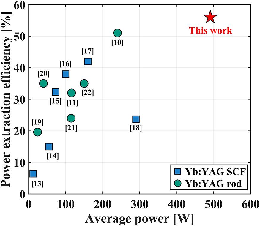
In this paper, we report a multi-stage pulsed amplification system with near 500 W average power and near-diffraction-limited output using laser diode (LD) end-pumped Yb:YAG rods. The designed system achieves a PEE of up to 56% at room temperature, primarily due to the complete elimination of crystal reabsorption. To the best of our knowledge, compared to previous MOPA systems based on LD end-pumped Yb:YAG crystals, our results exhibit significant improvements in both average power and PEE, as illustrated in Figure 1. A birefringence compensation method successfully reduces depolarization loss to 2.2%. In addition, near-diffraction-limited beam quality (M 2 = 1.26) was achieved at the near 500 W power level, after thermally induced spherical aberration was compensated using a phase plate. A preliminary pulse compression was also performed using a diffraction grating. The pulse duration is 859 fs after compression.
Typical power and PEE of LD end-pumped Yb:YAG SCF and rod amplifiers (square markers, Yb:YAG SCF amplifier; circular markers, Yb:YAG rod amplifier)[ Reference Wang, Cong, Liu, Zhang, Zhao and Liu10, Reference Veselis, Burokas, Ulčinas, Gertus, Michailovas and Michailovas11,Reference Zaouter, Martial, Aubry, Didierjean, Hönninger, Mottay, Druon, Georges and Balembois13–Reference Kuznetsov, Chizhov and Palashov22] .

2 Numerical simulation
2.1 Numerical model
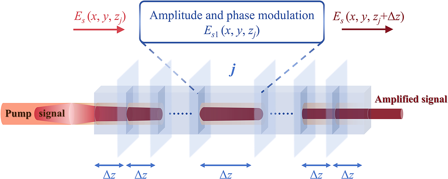
It is well known that Yb:YAG crystals exhibit significant absorption of laser emission when there is no pump or the pump intensity is low. This characteristic notably limits the PEE of Yb:YAG as an amplifier medium. A numerical model considering the signal and pump beam within the crystal rod, along with gain and absorption, was developed to mitigate crystal reabsorption. The crystal is mathematically divided into small segments along the longitudinal z-axis, each with a length of Δz, as shown in Figure 2.
Numerical model of the signal propagation in an end-pumped crystal rod.

The signal beam E s (x, y, z) is modulated in amplitude and phase by the gain and refractive index distributions within the jth slice:
 $$\begin{align}{E}_{\mathrm{s}1}\left(x,y,{z}_j\right)={E}_{\mathrm{s}}\left(x,y,{z}_j\right)\exp \left[\frac{g\left(x,y,{z}_j\right)}{2}\Delta z- i\varphi \left(x,y,{z}_j\right)\right],\end{align}$$
where φ (x, y, zj ) is the effective phase modulation[ Reference Beirow, Eckerle, Graf and Ahmed18, Reference Albrodt, Delen, Besbes, Lesparre and Georges23], while g (x, y, zj ) is the gain coefficient. In the Yb:YAG crystal, which exhibits quasi-three-level characteristics, the gain and absorption coefficients are modulated by the intensities of the signal and pump beams. These coefficients can be mathematically expressed as follows[ Reference Parvin, Ilchi-Ghazaani, Bananej and Lali-Dastjerdi24]:
 $$\begin{align} g\left(x,y,z\right)&=\left\{{I}_{\mathrm{p}}\left(x,y,z\right)\left[{\sigma}_{\mathrm{abs}}\left({\lambda}_{\mathrm{p}}\right){\sigma}_{\mathrm{em}}\left({\lambda}_{\mathrm{s}}\right)-{\sigma}_{\mathrm{abs}}\left({\lambda}_{\mathrm{s}}\right){\sigma}_{\mathrm{em}}\left({\lambda}_{\mathrm{p}}\right)\right]\right.\nonumber\\ &\quad \left.\cdot\, {N}_{\mathrm{t}}\tau /h{\nu}_{\mathrm{p}}-{\sigma}_{\mathrm{abs}}\left({\lambda}_{\mathrm{s}}\right){N}_{\mathrm{t}}\right\}\nonumber\\ &\quad \cdot \left[1+{I}_{\mathrm{p}}\left(x,y,z\right)/{I}_{\mathrm{p},\mathrm{sat}}\left(x,y,z\right)\right.\nonumber\\ &\quad \left. +\ {I}_{\mathrm{s}}\left(x,y,z\right)/{I}_{\mathrm{s},\mathrm{sat}}\left(x,y,z\right)\right]^{-1},\end{align}$$
 $$\begin{align}\alpha \left(x,y,z\right)&=\left\{{I}_{\mathrm{s}}\left(x,y,z\right)\left[{\sigma}_{\mathrm{abs}}\left({\lambda}_{\mathrm{p}}\right){\sigma}_{\mathrm{em}}\left({\lambda}_{\mathrm{s}}\right)-{\sigma}_{\mathrm{abs}}\left({\lambda}_{\mathrm{s}}\right){\sigma}_{\mathrm{em}}\left({\lambda}_{\mathrm{p}}\right)\right]\right.\nonumber\\ &\quad \left.\cdot\, {N}_{\mathrm{t}}\tau /h{\nu}_{\mathrm{s}}+{\sigma}_{\mathrm{abs}}\left({\lambda}_{\mathrm{p}}\right){N}_{\mathrm{t}}\right\}\nonumber\\ &\quad \cdot\, \left[1+{I}_{\mathrm{p}}\left(x,y,z\right)/{I}_{\mathrm{p},\mathrm{sat}}\left(x,y,z\right)\right.\nonumber\\ &\quad \left.+\, {I}_{\mathrm{s}}\left(x,y,z\right)/{I}_{\mathrm{s},\mathrm{sat}}\left(x,y,z\right)\right],\end{align}$$
where σ abs(λ p), σ em(λ p), σ abs(λ s), σ em(λ s) represent the absorption and emission cross-sections for the pump and signal, respectively, hv p and hv s are the energies of the pump and signal photons, N t is the density of Yb3+ ions, τ is the lifetime for the excited level and I p, I s, I p,sat, I s,sat represent the pump intensity, signal intensity and their corresponding saturation intensities. The saturation intensity can be written as follows:
 $$\begin{align}{I}_{\mathrm{p, sat}}=\frac{h{\nu}_{\mathrm{p}}}{\tau \left[{\sigma}_{\mathrm{abs}}\left({\lambda}_{\mathrm{p}}\right)+{\sigma}_{\mathrm{em}}\left({\lambda}_{\mathrm{p}}\right)\right]},\end{align}$$
 $$\begin{align}{I}_{\mathrm{s, sat}}=\frac{h{\nu}_{\mathrm{s}}}{\tau \left[{\sigma}_{\mathrm{abs}}\left({\lambda}_{\mathrm{s}}\right)+{\sigma}_{\mathrm{em}}\left({\lambda}_{\mathrm{s}}\right)\right]}.\end{align}$$
The angular spectrum theory, utilizing fast Fourier transform (FFT), has been validated for accurately simulating the signal propagation in the crystal[ Reference Xiang, Wang, Pan, Dong, Zhao, Li, Ge, Liu and Chen25, Reference Shen, Liu, Qiu, Jin, Liu, Ye, Liu and Liu26]. The propagation of the signal between adjacent slices is described as follows:
 $$\begin{align}{E}_{\mathrm{s}}\left(x,y,{z}_j+\Delta z\right)&={F}^{-1}\left\{F\left[\vphantom{\left({ik}_{\mathrm{c}}\Delta z\sqrt{1-{\lambda}_{\mathrm{s}}^2{f}_x^2-{\lambda}_{\mathrm{s}}^2{f}_y^2}\right)}{E}_{\mathrm{s}1}\left(x,y,{z}_j\right)\right.\right.\nonumber\\&\quad\left.\left. \times \exp \left({ik}_{\mathrm{c}}\Delta z\sqrt{1-{\lambda}_{\mathrm{s}}^2{f}_x^2-{\lambda}_{\mathrm{s}}^2{f}_y^2}\right)\right]\right\},\end{align}$$
where F, F –1 are the Fourier transform operator and inverse Fourier transform operator, respectively, fx , fy are the spatial angular frequencies in the Fourier domain, k c is the wave number of the signal beam in the crystal and λ s is the wavelength of the signal beam.
Assume that the transversal pump beam profile conforms to a super-Gaussian function and is not influenced by the thermal lens. The relationship between the pump intensities I p (x, y, z) in adjacent slices can be expressed as follows:
 $$\begin{align}{I}_{\mathrm{p}}\left(x,y,{z}_j+\Delta z\right)&={C}_0\exp \left[\frac{-2{\left(\sqrt{x^2+{y}^2}\right)}^{N_{\mathrm{p}}}}{\omega_{\mathrm{p}}{\left({z}_j+\Delta z\right)}^{N_{\mathrm{p}}}}\right]\nonumber\\&\quad \times \underset{z=0}{\iint }{I}_{\mathrm{p}}\left(x,y,{z}_j\right)\exp \left[-\alpha \left(x,y,{z}_j\right)\Delta z\right]\mathrm{d}x\mathrm{d}y,\end{align}$$
 $$\begin{align}{\omega}_{\mathrm{p}}(z)={\omega}_{\mathrm{p}0}\sqrt{1+{\left[\frac{\lambda_{\mathrm{p}}{M}_{\mathrm{p}}^2}{n_{\mathrm{c}}{\pi \omega}_{\mathrm{p}0}^2}\left(z-{z}_0\right)\right]}^2},\end{align}$$
where N p is the super-Gaussian order, ω p0 is the waist radius of the pump beam, z 0 is the waist position of the pump beam, λ p is the wavelength of the pump beam, M p2 is the beam quality of the pump beam, n c is the refractive index of the Yb:YAG crystal and C 0 is the normalization factor:
 $$\begin{align}{C}_0=\frac{1}{\underset{z=0}{\iint}\exp \left[\frac{-2{\left(\sqrt{x^2+{y}^2}\right)}^{N_{\mathrm{p}}}}{\omega_{\mathrm{p}}{\left({z}_j+\Delta z\right)}^{N_{\mathrm{p}}}}\right]\mathrm{d}x\mathrm{d}y}.\end{align}$$
2.2 Simulation results
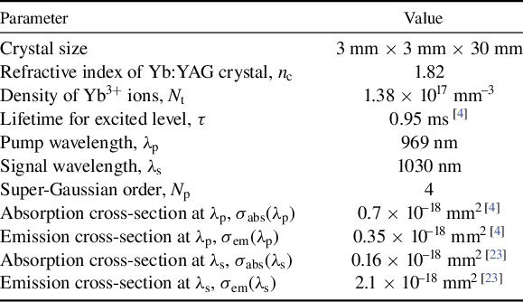
The parameters utilized in the simulation are presented in Table 1. In the simulation, 160 W of 969 nm pump laser was end-injected into a 3 mm × 3 mm × 30 mm, 1% (atomic fraction) doped Yb:YAG crystal. A fundamental mode signal with an average power of 14 W was injected coaxially, in the same direction as the pump.
Parameters for numerical simulation.

The numerical model developed was employed to simulate and analyze the factors affecting reabsorption and PEE, as illustrated in Figure 3. The simulation results reveal that several factors, including waist size, position, brightness of the pump beam and signal size, significantly influence PEE, as shown in Figures 3(a)–3(c). PEE exhibits a non-monotonic dependence on the pump beam waist size, initially increasing and subsequently decreasing as the waist size expands. In addition, PEE of a low-brightness pump consistently remains lower than that of a high-brightness pump. The other two parameters demonstrate similar trends to the pump beam waist size. It is evident that, as these four factors vary, an optimal point exists where PEE reaches its maximum. Besides, PEE remains relatively stable near the optimal point, so amplifier parameters will be selected within this range to determine the most effective experimental values. As depicted in Figure 3(d), the influence of the signal beam’s divergence angle is also considered. By varying the focal length of the signal lens while maintaining a constant signal spot size at the lens, the results reveal a consistent trend with the other factors, yet exhibit minimal variation in comparison. Consequently, the divergence angle of the signal beam has a negligible effect on PEE.
Simulation results for the influence of reabsorption and PEE in an Yb:YAG rod: (a)–(d) the effect of brightness, waist diameter, waist position of the pump beam and diameter and divergence angle of the signal beam on PEE; (e) comparison of signal power variations within the crystal for the optimal and worst parameter combinations.

The parameter optimization process is outlined as follows: initially, all parameters to be optimized are assigned random initial values based on prior experience. The first parameter is selected, and its value is systematically varied within a suitable range while keeping the other parameters constant. The optimized value of the first parameter is then recorded, and the process proceeds to the second parameter. The entire process is iterated to incrementally converge toward the optimal value for each parameter until the error criterion is satisfied. Figures 3(a)–3(d) present the final optimized results, with each parameter varied while the others are fixed at their optimal values. In addition, to visually illustrate the reabsorption within the crystal, the parameter combinations in the simulation that resulted in the highest and lowest PEE were compared, as shown in Figure 3(e). It can be observed that low PEE is attributed to reabsorption occurring at lower pump intensity near the crystal’s end. In contrast, reabsorption was eliminated after optimizing these key factors, leading to a 25% increase in PEE.
Schematic diagram of the Yb:YAG laser amplifier–compressor. HWP, half-wave plate; PBS, polarizing beam splitter; M1–M8, high reflectivity mirrors; DM, dichroic mirror.

Since the power limitations in practical operation are related not only to PEE but also to multiple factors, such as thermal effects, damage threshold and so forth, the numerical model presented incorporates simulations of average power, PEE and the impact of the thermal lens effect on the signal beam. However, it does not account for the effect of temperature rise on the quasi-three-level characteristics of the Yb:YAG crystal, representing a primary focus for further model refinement. The simulation results currently align well with experimental data. In high-power laser operation, the damage threshold is a critical factor requiring careful consideration. During experimental parameter design, this model was employed to calculate the peak power density of the signal beam throughout two amplifiers, ensuring it remains within the safe damage threshold range of the components.
3 Experimental setup
The experimental setup is shown in Figure 4. The seed source consists of an Yb-doped fiber master oscillator combined with an Yb:YAG thin-rod amplifier. The repetition rate of the seed laser can be adjusted from 100 kHz to 1 MHz, with a maximum output power of 20 W and a pulse width of approximately 650 fs. For the implementation of CPA technology, the seed laser, with a stretched pulse width of approximately 80 ps, was extracted before final compression. As shown in Figure 5(a), in this work, the repetition rate of the seed laser was set to 1 MHz, with an average power of 14 W and a beam quality factor of 1.15. A half-wave plate and a polarizing beam splitter (PBS) before the isolator were used to adjust the power of the seed laser independently.
Two 3 mm × 3 mm × 30 mm Yb:YAG rods with 1% (atomic fraction) doping served as the gain medium in the first-stage amplifier. The crystals were attached to a water-cooled microchannel copper heat sink, with the water temperature maintained at 20°C. Two high-brightness, fiber-coupled 969 nm LDs with a 106.5 μm diameter and a numerical aperture of 0.22, delivering a maximum output power of 160 W, were employed to pump the rods. In-band pumping was utilized to minimize quantum losses and heat generation, while high-brightness pumping enhances the PEE of low-power amplification in the first-stage amplifier. The pump laser was collimated and expanded using a lens system, and then imaged into the rod 12.7 mm away from the entry face, achieving a waist diameter of 0.46 mm. The seed laser was pre-focused before entering the first rod, resulting in a spot diameter of 0.52 mm at the rod’s entry face. A 4f system, consisting of two 200 mm focal length lenses (L3 and L4), was used to image the end faces of the two rods onto one another. A 90° quartz rotator was inserted to effectively compensate for birefringence. A PBS at the output (PBS2) was used to filter out the minor depolarization component from the amplified signal.
Temporal characterization of the laser pulses: (a) seed; (b) the second-stage amplifier.

The structure of the second-stage amplifier is nearly identical to that of the first stage, except for the use of two 400 W, 969 nm LDs with a 200 μm fiber core diameter and a numerical aperture of 0.22 for the pump module. In the second-stage amplifier, both the signal and pump beam sizes were increased to avoid optical damage during the high-power amplification process. The pump beam was imaged at the same position within the rod as in the first stage, but its waist diameter was enlarged to 0.66 mm. Meanwhile, the seed laser diverged into the third rod, with a diameter of 0.87 mm at the entry face. A plano-concave lens (L8) with a focal length of –100 mm was placed near the entry face of the fourth rod to mitigate the thermal lens effect. After the second-stage amplification, the depolarization components were filtered out by PBS3, and a phase plate (customized by Hangzhou Wavelength Optoelectronic Technology) was used to compensate thermally induced spherical aberration[ Reference Xie, Zhou, Qiu, He, Chen, Wu, Dong, Chen, Liu, Chen, Ju and Liu27]. The phase plate, constructed from quartz, features a 1030 nm high-transmission (HT) coating on its surface. Its high damage threshold ensures sustained performance under high peak power density laser conditions. The phase plate is customized for a specific pump power. As different pump powers induce varying thermal effects, the corresponding thermally induced spherical aberration coefficients also differ. Consequently, a distinct phase plate design is required for each pump power condition. Part of the amplified signal was then directed into a diffraction grating for preliminary pulse compression.
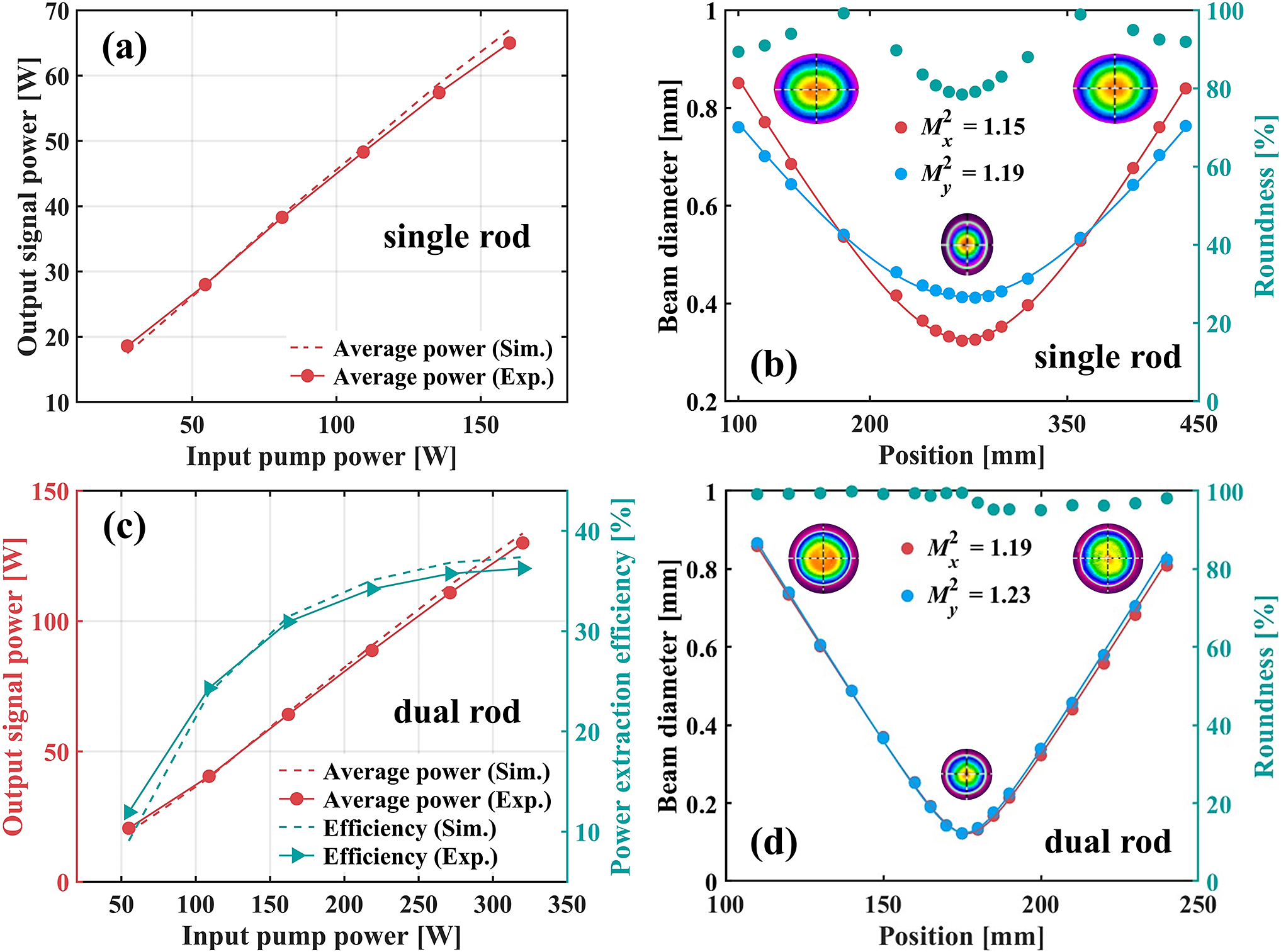
Experimental results of the first-stage amplifier: (a) signal output power versus pump power (single rod); (b) beam profile and roundness before birefringence compensation (single rod); (c) signal output power and PEE versus pump power (dual rod); (d) beam profile and roundness after birefringence compensation (dual rod).
4 Experimental results and discussion
The first rod (Yb:YAG1) is operated at low saturation regime, yielding high gain, as shown in the Figure 6(a). It delivered an average power of 65 W, including 1.8 W of depolarized power, corresponding to a depolarization ratio of 2.7%, when the pump power was 160 W. Although the current thermally induced birefringence effect is weak, it still noticeably reduced the roundness of the signal laser, as shown in Figure 6(b). The lower roundness is detrimental to subsequent amplification, necessitating an effective compensation method. A dual-rod configuration was employed to compensate for birefringence. A 90° quartz rotator was inserted between two rods with similar thermal effects, ensuring that the radial and tangential polarization components at every point in the first rod were exchanged in the second rod. In addition, a 4f optical system was employed to direct the beam focused by the thermal lens to propagate in the same region in both rods, thereby effectively compensating for the birefringence effect. In the dual-rod cascaded, a total pump of 320 W resulted in a PEE of 36.5%, as illustrated in Figure 6(c). The simulation results and experimental data demonstrate excellent agreement. Due to the limited seed power, PEE remains relatively low even after optimizing the parameters of the first-stage amplifier, but it was significantly improved in the second stage. An average power of 130 W and a depolarization ratio of 0.5% were obtained. Figure 6(d) demonstrates that the average beam roundness increased to 98% after birefringence compensation. The extremely low depolarization ratio and high beam roundness validate the effectiveness of the compensation method. Furthermore, the M 2 factors in both horizontal and vertical directions after compensation were measured to be 1.19 and 1.23, respectively. The higher gain and PEE of the first-stage amplifier ensure that the signal beam quality does not deteriorate significantly.
Experimental results of the second-stage amplifier: (a) signal output power and PEE versus pump power; (b) comparison of the depolarization ratio with and without birefringence compensation versus pump power; (c) beam quality after spherical aberration compensation at 483 W average power; (d) variation of the output power of the amplified signal compensated by the phase plate over 6 h.

Thermally induced birefringence was successfully compensated in the first-stage amplifier, and the same method was applied to the second stage. As shown in Figure 7(a), the signal output power reached 494 W with a pump power of 650 W, resulting in a notable PEE of 56%. The consideration of the damage threshold limits the pump power of the second-stage amplifier. Further pulse stretching would enable higher pump power, thereby increasing the amplified signal power. Figure 7(b) highlights the effectiveness of our birefringence compensation method. The high-intensity pump employed to achieve high PEE induced substantial heat deposition in the second-stage amplifier, resulting in significant depolarization losses. In the absence of birefringence compensation in the dual-rod configuration, the depolarized power was 88 W, corresponding to a depolarization rate of 17.8% under a 650 W pump power. However, with the compensation method, a low depolarization ratio of 2.2% was achieved, yielding 483 W of linearly polarized signal power output. To the best of our knowledge, this represents the lowest depolarization ratio ever reported for Yb:YAG rod amplifiers at near 500 W power scales. On the other hand, the second-stage amplifier is operated in a saturated state, yielding low gain. Although its PEE is markedly improved compared to the first-stage amplifier, the amplifier’s thermal effects increase substantially with higher pump power. Therefore, thermally induced wavefront aberrations caused a rapid deterioration in beam quality following amplification. The M 2 factor of the amplified signal, following birefringence compensation, was measured to be approximately 2.0. Previous studies have shown that spherical aberration is a primary contributor to beam quality degradation[ Reference Xie, Zhou, Qiu, He, Chen, Wu, Dong, Chen, Liu, Chen, Ju and Liu27– Reference Qi, Zhao, Liu and Xiang30]. Given that birefringence compensation has been fully addressed, the observed beam quality degradation is attributed to spherical aberration. A phase plate was employed to effectively eliminate this aberration, enhancing beam quality without any loss of power. As shown in Figure 7(c), the high-power beam was restored to the fundamental mode after the spherical aberration compensation, with M 2 factors both below 1.30. Figure 7(d) shows the long-term power stability of the amplifier operating at 483 W. The standard deviation (SD) of the measured power was calculated to be 0.2 over a 6-h period. In addition, the depolarization rate and the beam quality were reassessed after 6 h, revealing no significant changes.
The spectral and temporal characteristics of the signal pulse: (a) the spectra of signals from the seed, the first-stage amplifier and the second-stage amplifier; (b) the compressed pulse duration measured from the autocorrelator.

Considering the damage threshold, a 50 W amplified laser from the second stage was coupled into a diffraction grating with a compression efficiency of 90%. A spectrometer (from Yokogawa) and an autocorrelator (from APE) were utilized to assess the spectral and temporal characteristics of the amplified signal, as depicted in Figure 8. The spectral width was narrowed from 1.8 nm (for the seed laser) to 1.4 nm as a result of the gain narrowing effect. In addition, the diffraction grating compressed the pulse duration of the amplified signal to 859 fs. In future work, the gain narrowing effect can be mitigated by optimizing the seed laser’s spectrum, enabling the compressed pulse duration to more closely approach the Fourier transform limit.
5 Conclusion
In conclusion, a high-power, high-efficiency Yb:YAG rod amplifier was demonstrated. Using the established numerical model to analyze reabsorption within the Yb:YAG crystals, we determined four key influencing parameters: the beam waist size and position of the pump, its brightness and the signal size. Through parameter optimization, reabsorption in the Yb:YAG crystals was effectively eliminated, significantly enhancing the amplifier’s PEE. The high-intensity pump used to overcome the reabsorption caused intense thermal effects in the amplifier, leading to severe depolarization losses and beam quality degradation. An efficient birefringence compensation method was employed to correct beam distortion and minimize depolarization losses. As a result, the second-stage amplifier achieved a PEE of 56%, delivering 483 W of linearly polarized average power with a negligible depolarization loss of only 2.2%. By compensating for spherical aberration with a phase plate, the M 2 factor of the amplified signal was improved to 1.26, resulting in a nearly diffraction-limited beam at near 500 W average power. Finally, a diffraction grating was used for the preliminary pulse compression, achieving a pulse duration of 859 fs with a compression efficiency of 90%. Our results demonstrate that Yb:YAG rods are a highly promising gain medium for high-power femtosecond amplifiers when their disadvantages are addressed at room temperature.
Acknowledgements
This work was supported by the Primary Research and Development Plan of Zhejiang Province (Grant No. 2024C03033), the Joint Fund of Zhejiang Provincial Natural Science Foundation (Grant No. LQZSZ25F050001) and the Open Foundation of State Key Laboratory of Extreme Photonics and Instrumentation, Zhejiang University.


 Open access