


1 Introduction
Ultrafast lasers, capable of generating optical pulses with ultrashort pulse widths and high peak powers, play crucial roles in the field of precision manufacturing, such as cutting[ Reference Beausoleil, Yazdani Sarvestani, Katz, Gholipour and Ashrafi1], welding[ Reference Chen, Xie, Duan, Xiong and Deng2] and surface treatment[ Reference Palmieri, Ledesma, Dennie, Kramer, Lin, Hopkins, Wohl and Connell3]. Although high-reflection mirrors and retroreflective optics can be used to achieve high-efficiency delivery of ultrafast pulses, such free-space systems exhibit, generically, high sensitivity to environments and require regular maintenances. In addition, the relatively complex setup somewhat limits the flexibility and stability of free-space laser beam delivery systems, restricting the application scope of advanced laser-micromachining equipment. Consequently, flexible delivery of high-power ultrafast lasers over optical fiber is greatly required for laser-micromachining applications[ Reference Tirlapur and König4– Reference Petrarca, Henin, Berti, Matthews, Chagas, Kasparian, Wolf, Gatti, Di Pirro, Anania, Ferrario and Ghigo6].
Even though conventional solid-core fiber, as a mature technique for high-average-power laser delivery[ Reference Mulvad, Abokhamis Mousavi, Zuba, Xu, Sakr, Bradley, Hayes, Jasion, Fokoua, Taranta, Alam, Richardson and Poletti7, Reference Yao, Zhang, Li, Wang, Jin, Duan, Zhao and Wang8], has been widely used for the transmission of continuous-wave (CW) or quasi-CW laser light, high-fidelity transmission of high-power ultrafast pulses with μJ-level pulse energies over such solid-core fiber is impossible. Due to the extremely high peak power on the fiber-end surface and excessive nonlinearity accumulation over the fiber length, disastrous material damage and pulse distortion cannot be avoided during ultrafast pulse propagation in solid-core fiber. In contrast, the development of anti-resonant hollow-core fiber (AR-HCF)[ Reference Zhang9– Reference Gao, Zha, Feng, Liang, Sun, Yang and Wang14] provides a promising possibility of high-fidelity delivery of high-power ultrafast laser pulses, thanks to its intrinsic features of ultra-low nonlinearity, ultra-high damage threshold and weak waveguide dispersion[ Reference Antesberger, Richter, Poletti, Slavík, Petropoulos, Hübel, Trenti, Walther and Rozema15– Reference Yan, Li, Huang, Wang, Liu, Liu, Pan, Luo, Yang, Zheng, Yin, Yu, Leng, Song, Pang and Jiang17]. Although a few studies on high-peak-power laser pulse delivery over AR-HCF have been demonstrated in recent years[ Reference Lekosiotis, Belli, Brahms, Sabbah, Sakr, Davidson, Poletti and Travers18– Reference Liang, Guan, Zhu, Wang, Wu, Yu and Han20], the performance of such an AR-HCF delivery system in practical laser micromachining, especially the influence of transmitted optical-mode purity on the manufacturing quality, has not been studied yet.
In this work, we studied the AR-HCF delivery of 20 W picosecond laser pulses at 1064 nm in laser-micromachining experiments, illustrating, for the first time to our knowledge, the importance of the fiber optical-mode quality for micromachining quality. We demonstrated experimentally that AR-HCF with a capillary to core (d/D) ratio of approximately 0.68[ Reference Uebel, Günendi, Frosz, Ahmed, Edavalath, Ménard and Russell21] can efficiently overcome the problem of high-order-mode excitation due to the movement and sway of the fiber sample. We found that the ultrafast laser light, after flexible delivery over a d/D = ~0.68 AR-HCF sample, exhibits better optical-mode purity under external perturbations than that delivered over a d/D = ~0.5 AR-HCF sample. This improved mode stability results in perfect circularity of the manufactured spots with better consistency in the single-shot micromachining experiment, and in the in-line processing experiment, the good mode purity leads to relatively straight processing lines, similar to those achieved using a free-space delivery system. Our findings highlight the importance of high optical-mode purity of AR-HCF for improving laser manufacturing quality.
2 Experimental setup
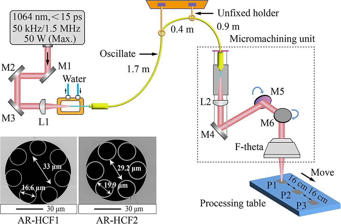
The experimental setup is sketched in Figure 1. The light source was a commercial picosecond solid-state laser (HyperRapid NX, 1064-50) with a lasing wavelength of 1064 nm, a tunable repetition rate up to 1.5 MHz, a pulse width of less than 15 ps and a spectral bandwidth of less than 0.11 nm. The maximum output average power of the laser is 50 W. As shown in Figure 1, the output laser beam has a diameter of approximately 5 mm, aligned by a set of reflectors (M1–M3). To match the fiber mode field, the laser beam was focused by a plano-convex lens (L1) with a focal length of 7.5 cm, giving rise to an in-fiber coupling efficiency of approximately 85%, with all experimental AR-HCFs using this identical lens configuration. The further improvement of the coupling efficiency is mainly limited by the perfect matching of the mode field diameter and the beam quality and stability of the laser. The achieved efficiency of 85% is sufficient for the application here, although further optimization of the laser source or beam shaping can further improve efficiency. In the experiment, an approximately 1-cm-long coating area of the AR-HCF was stripped off, so as to avoid heat-related damage due to uncoupled laser power. The AR-HCF end-facets were prepared by cleaving only, and then the bare fiber end was mounted on a copper plate using a three-dimensional stage (Elliot MDE122) and fixed with copper tape. Note that in the experiment, a water-cooling system was used to reduce the thermal effects of the copper plate at high laser powers. To prevent AR-HCF degradation during experiments, alignment was first optimized at low power using the three-dimensional stage. Power was then increased stepwise, with timely feedback ensuring sustained alignment. The overall transmission efficiency of the 3-m-long AR-HCF system, including the in-fiber coupling, was measured to be approximately 76%. The fiber loss of the AR-HCF used in the experiment was measured to be approximately 0.1 dB/m at the pump wavelength of 1064 nm; see the Supplementary Material for details.
Experimental setup. M1–M4 are optical reflectors with a reflectivity of more than 99.5%; M5 and M6 are moving mirrors; L1 and L2 are plano-convex lenses with focal lengths of 7.5 cm. The AR-HCF is encased within a protective metallic cable, and the AR-HCF input port is installed on a copper plate. Two unfixed holders are used in the latter half of the AR-HCF to ensure the flexible movement of the micromachining unit. Three aluminum sheets are placed at three different positions (P1–P3) on the processing table at intervals of 16 cm. Inset: SEM images of AR-HCF1 and AR-HCF2, with d/D values of approximately 0.5 and 0.68, respectively.

The AR-HCF sample is encased within a protective metallic cable, suspended from hooks anchored to the ceiling, to ensure its vertical ingress into the micromachining unit. The minimum bending radius of the fiber after encasing is approximately 30 cm. At the output end of the AR-HCF inside the micromachining unit (see Figure 1), the laser beam was collimated by a plano-convex lens (L2) with a focal length of 7.5 cm installed in the cage system, and then reflected by a mirror (M4). Through the moving-mirror system (M5 and M6), the laser beam was then focused onto the surface of the material under processing (thick aluminum sheets in our experiments) by an F-theta lens. Two AR-HCF samples with different parameters (AR-HCF1: d = 16.6 μm, D = 33 μm, d/D = ~0.5; AR-HCF2 with improved optical-mode purity[ Reference Uebel, Günendi, Frosz, Ahmed, Edavalath, Ménard and Russell21, Reference Luo, Huang, Zheng, Yin, Zhang, Jiang and Pang22]: d = 19.9 μm, D = 29.2 μm, d/D = ~0.68) were used in the experiment. The selection of the d/D ratio was based on the modified Marcatili–Schmeltzer model and finite element simulations, where a d/D ratio parameter close to 0.68 can enhance the suppression of the LP11 mode[ Reference Uebel, Günendi, Frosz, Ahmed, Edavalath, Ménard and Russell21]. Scanning electron microscope (SEM) images of the two AR-HCF samples are shown in the inset of Figure 1.
3 Results and discussion
As the average power of the AR-HCF output port gradually increased from 0.7 to 20 W, we observed no significant change in either pulse temporal width or spectral profile at the output port of the 3-m-long AR-HCF, thanks to the low nonlinearity and dispersion values of the fiber. This has been confirmed by simulation results based on the generalized nonlinear Schrödinger equation; see the Supplementary Material for details. In the experiment, a free-space laser beam delivery system was also constructed, and the power and pointing stability of the laser beam after transmission in the free-space system, the 3-m-long AR-HCF1 sample and the 3-m-long AR-HCF2 sample were measured for comparison. As illustrated in Figure 2, the output light in these three cases exhibits similar power stability at a power level of approximately 20 W, giving root mean square (RMS) values of power fluctuations all at approximately 0.2% over 30-min recordings; see Figures 2(a), 2(c) and 2(e). Note that we observed no damage of the AR-HCF end-faces over several weeks of experiments and the measured RMS values remained almost unchanged, highlighting the good power stability of the ultrafast laser fiber-delivery system.
Power stability (a) and pointing stability (b) of the free-space laser delivery system, respectively. (c), (d) Results of the 3-m-long AR-HCF1 laser delivery system. (e), (f) Results of the 3-m-long AR-HCF2 laser delivery system.
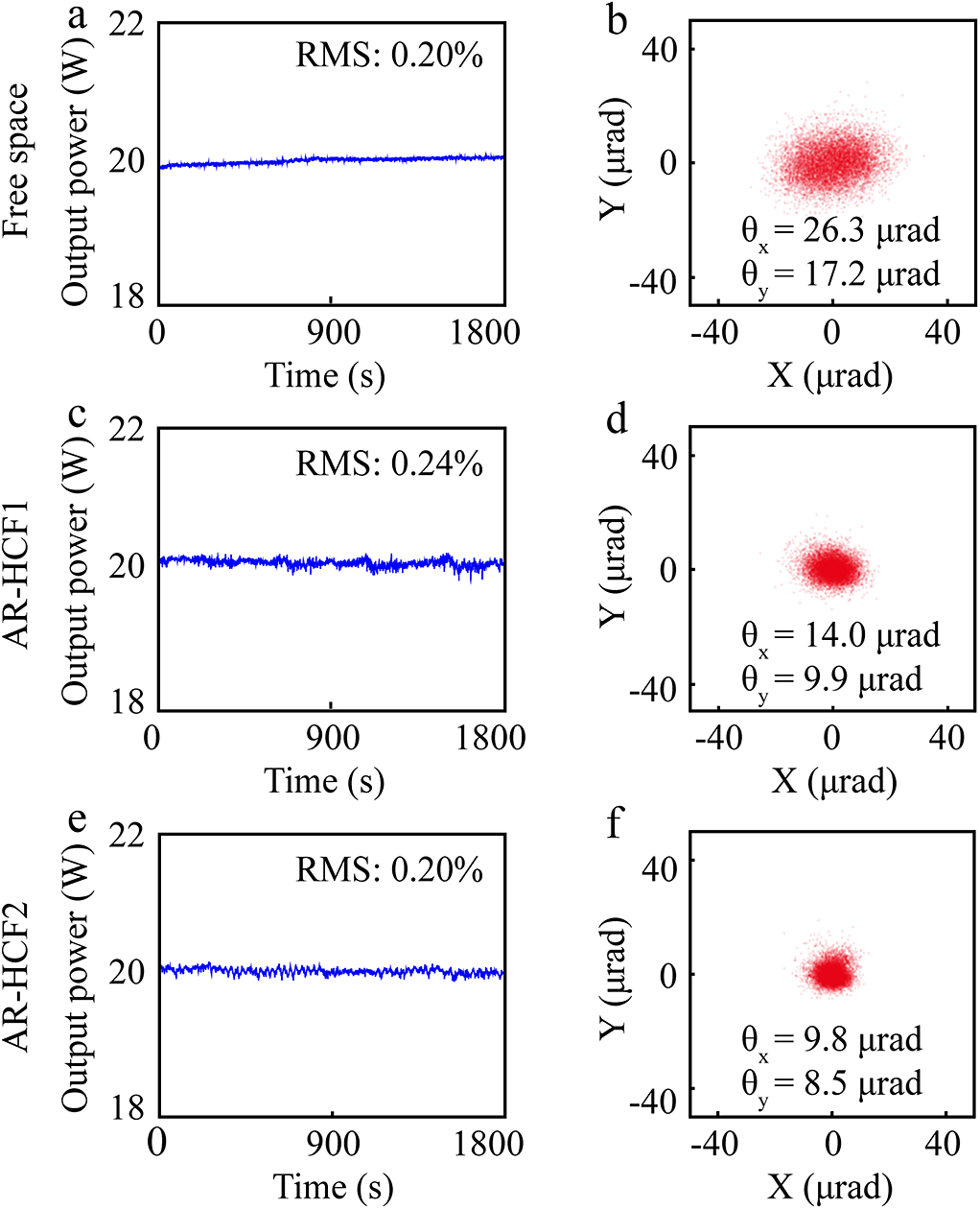
Before being used in the micromachining experiment, the laser beam-profile outputs from the three delivery systems were measured using a charge-coupled device (CCD) camera, and their pointing stabilities (the stabilities of the laser beam weight centers) were calculated over 30-min recordings. The results are illustrated in Figures 2(b), 2(d) and 2(f). It can be found that the pointing stability of the free-space delivery system (θx = 26.3 μrad and θy = 17.2 μrad) is obviously worse than those of the two AR-HCF delivery systems, which can be mainly attributed to the 3-m propagation length of the laser beam in free space. In contrast, in the fiber-delivery system the output laser beam was directly coupled into the AR-HCF sample after merely a short length of free-space propagation, largely improving the pointing stability of the transmitted beam. It can be seen in Figure 2 that the performance (θx = 9.8 μrad and θy = 8.5 μrad) of the AR-HCF2 sample is a few better than that (θx = 14.0 μrad and θy = 9.9 μrad) of the AR-HCF1 sample. This is because the high-order-mode suppression ability of the AR-HCF2 sample (d/D ≈ 0.68[ Reference Uebel, Günendi, Frosz, Ahmed, Edavalath, Ménard and Russell21]) ensures highly pure fundamental optical mode at the output port of the fiber.
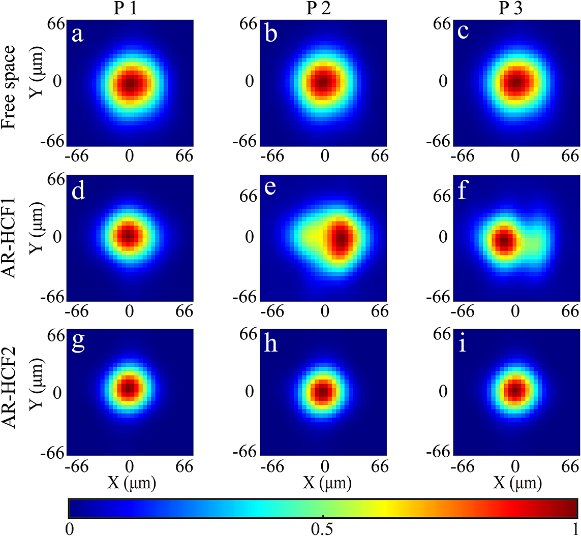
The highly pure mode performance of the AR-HCF2 sample was further verified through measuring directly the laser beam profile at the fiber output port, as illustrated in Figure 3. It can be found that for the free-space delivery system, the Gaussian-like beam profile remained stable (see Figures 3(a)–3(c)) as the laser-micromachining unit moved, while for the AR-HCF1 system obvious optical-mode degradation was observed (see Figures 3(d)–3(f)) as the unit moved, which can result from some micro-bending of the AR-HCF1 sample. Such micro-bending gives rise to certain energy coupling from the fundamental optical mode to some high-order modes of the fiber, leading to beam-profile instability. This beam-profile instability can be efficiently eliminated through using the AR-HCF2 sample (see Figures 3(g)–3(i)), since the high-order modes in this fiber have much higher loss than the fundamental optical mode[ Reference Uebel, Günendi, Frosz, Ahmed, Edavalath, Ménard and Russell21, Reference Luo, Huang, Zheng, Yin, Zhang, Jiang and Pang22], giving enhanced capability of high-order-mode suppression. A highly pure fundamental optical mode with a Gaussian-like shape was always obtained at the fiber output port, which was immune to external perturbations.
Measured beam profiles at the output ports of the laser delivery systems over free space (a)–(c), the 3-m-long AR-HCF1 (d)–(f) and the 3-m-long AR-HCF2 (g)–(i).
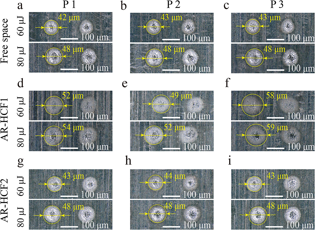
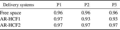
The good laser-delivery performance of the AR-HCF2 sample was confirmed in practical laser-micromachining experiments. When 2-mm-thick aluminum sheets were used as the material under processing, we first set the laser to operate in the single-pulse model and the pulse energies on the materials were adjusted to be 60 and 80 μJ. Three pieces of aluminum sheets were placed at three different positions (P1–P3) on the working platform with 16 cm intervals between them; see Figure 1. We found in the experiment that as we move the micromachining unit to different positions, the output beam profiles from the AR-HCF1 sample are different due to different micro-bending conditions of the fiber, which can lead to inconsistent single-shot processing results on the aluminum surfaces; see Figures 4(d)–4(f). For the free-space and AR-HCF2 cases, the stable beam profiles (see Figure 3) ensure better consistency of the single-shot processing results. The spot diameters were measured to be approximately 43 μm at 60 μJ pulse energy and approximately 48 μm at 80 μJ pulse energy; see Figures 4(a)–4(c) and 4(g)–4(i). In addition, the experimental results establish a clear relationship between beam quality (M², provided in the Supplementary Material) and micromachining performance: lower M² values (approaching the ideal 1.0) significantly improve spot circularity and dimensional uniformity. For quantitative analysis, we measured spot circularity at 80 μJ pulse energy using ImageJ software, with M² values closer to 1.0 corresponding to higher circularity. The measurement results are shown in Table 1.
Single-shot processing results on the surfaces of aluminum sheets using picosecond laser beams delivered over free space (a)–(c), the 3-m-long AR-HCF1 (d)–(f) and the 3-m-long AR-HCF2 (g)–(i).
The measurement results of spot circularity in single-shot processing.

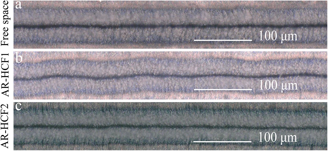
In the experiment, we also performed the in-line processing procedure when the AR-HCF was in an oscillating state (see Figure 1). The laser pulse-repetition rate was set to 1.5 MHz and the pulse energy on the aluminum surface was adjusted to approximately 13 μJ, corresponding to an average laser power of approximately 20 W. At a scanning speed of 4 mm/s, the in-line processing results of laser beams from the free-space, 3-m-long AR-HCF1 and 3-m-long AR-HCF2 delivery systems are illustrated in Figures 5(a)–5(c), respectively. It can be seen in Figure 5(b) that the in-line processing results using the AR-HCF1 sample exhibit obvious displacements from the perfectly straight line, which can be attributed to the instability of the output beam from the fiber. As illustrated in Figure 5(c), such displacements can be reduced through using the AR-HCF2 sample, largely improving the manufacturing quality. It can also be found from Figures 5(a) and 5(c) that the manufacturing quality of the AR-HCF2 delivery system is almost the same as that of the free-space delivery system, with however improved configuration flexibility and reduced maintenance cost. The quality difference in the processing results of these three laser delivery systems mainly depends on the stability of the output beam. Some more detailed results and discussions are shown in the Supplementary Material. To quantitatively evaluate the quality of the in-line processing, we estimated the degree of displacement (defined as the ratio of the standard deviation to its mean value) for these in-line processing results, and the estimated degrees of displacement are 2.12%, 5.66% and 2.38% for the free-space, AR-HCF1 and AR-HCF2 delivery systems, respectively. Some detailed information can be found in the Supplementary Material.
In-line processing results on the surfaces of aluminum sheets using approximately 20 W picosecond laser delivered over free space (a), the 3-m-long AR-HCF1 (b) and the 3-m-long AR-HCF2 (c), all at 4 mm/s scanning rates.

4 Conclusion
In conclusion, we demonstrated the high-quality delivery of high-power, picosecond laser pulses over a 3-m-long AR-HCF sample for laser-micromachining applications. The experiment results show that the AR-HCF sample with a d/D value of approximately 0.68 exhibits high optical-mode purity, which is critical for overcoming the laser beam instability due to fiber micro-bending. Single-shot and in-line processing procedures of aluminum sheets were performed in our experiments, verifying that the ultrafast laser beam delivered through the 3-m-long AR-HCF sample can be used to achieve similar manufacturing quality to that delivered over free space. Our findings provide some insightful guidelines for developing ultrafast laser-micromachining equipment based on the flexible AR-HCF delivery technique.
Supplementary material
The supplementary material for this article can be found at http://doi.org/10.1017/hpl.2025.10063.
Acknowledgements
The authors thank Dr. Xiaocong Wang and Dr. Kaixuan Li for their helpful discussions on AR-HCF mode purity characterization. This work was supported by the National Natural Science Foundation of China (Grant Nos. 62205353 and 62275254), the Strategic Priority Research Program of the Chinese Academy of Sciences (Grant No. XDB0650000), the Shanghai Science and Technology Plan Project Funding (Grant No. 23JC1410100) and the Fuyang High-level Talent Group Project.


 Open access