


NOMENCLATURE
- AR
Wing aspect ratio
- b
Wingspan (m)
- cg
Geometric chord (m)
- CL
Lift coefficient
- CD
Drag coefficient
- CL/CD
Lift to drag ratio
- ct
Fuel consumption rate
- D
DRAG (N)
- E
Flight endurance (h)
- Ixx
Mass moment of inertia (kgm2)
- L
LIFT (N)
- Lroll
Rolling moment (Nm)
- mw
Wing mass (kg)
- p
Roll rate
- q
Dynamic pressure (Pa)
- R
Flight range (km)
- S
Wing reference area (m2)
- V
Speed (m/s)
- W0
Takeoff weight (N)
- W1
landing weight (N) $\rho $
Air density (kg/m3)
- ${\tau _s}$
Time constant


1.0 INTRODUCTION
The goal of designing a morphing wing is to allow the UAV to achieve its mission requirements in various flight conditions. Enhancing the performance and improving controllability and manoeuverability of aerial vehicles have attracted considerable attention in aerospace research(Reference Ajaj, Bourchak and Friswell1–Reference Pecora, Barbarino, Concilio, Lecce and Russo3). The capability of changing the wing aspect ratio allows the UAV to achieve its mission smoothly during various flight stages(Reference Ajaj, Flores, Friswell, Allegri, Woods, Isikveren and Dettmer4). Moreover, it enables the UAV to increase its aerodynamic performance and efficiency. For instance, prolonged spans led to significant improvements in aerodynamic performance and fuel efficiency. However, they also decrease the manoeuverability and limit the cruise velocities. On the opposite side, the low aspect ratio wings give more manoeuverability and increase aircraft speed with a reduction in flight performance and an increase in fuel consumption(Reference Ajaj, Bourchak and Friswell1,Reference Ajaj, Flores, Friswell, Allegri, Woods, Isikveren and Dettmer4,Reference Della Vecchia, Corcione, Pecora, Nicolosi, Dimino and Concilio5) .
The main concepts of the morphing wing can be classified into three major types as follows(Reference Tarabi, Ghasemloo and Mani6):
Planform alternation: In this type, the wing can manipulate its shape dimensions, such as its span, chord length, and sweep angle.
Out-of-plane transformation: Wing out-of-plane transformation is mainly based on three parameters, which include the span-wise bending, the chord-wise bending, and the wing twisting.
Aerofoil adjustment: Aerofoil adjustment is mainly affected by two parameters: camber variation and thickness, which can reshape the aerofoil(Reference Sofla, Meguid, Tan and Yeo7,Reference Barbarino, Bilgen, Ajaj, Friswell and Inman8) .
With the growing use of the UAV in various domains, civil and military applications, the morphing aircraft technology area is reinforced in the current and upcoming periods of time(Reference Arena, Concilio and Pecora9). The morphing concept provides massive benefits such as:
Increasing the flight range by improving aerodynamic efficiency.
Achieving multiple tasks to carry out radically new manoeuvers without using conventional control surfaces.
Reducing drag force to enhance fuel efficiency, which leads to the flight envelope extension.
Reducing vibration and flutter by enhancing structural capability.
The variable span morphing wing provides an excellent capacity for achieving multiple tasks(Reference Concilio, Dimino, Ciminello, Pecora, Amoroso and Magnifico10). By changing the span length and wetted area, the wing addresses numerous mission segments such as cruising, loitering, long flight range, manoeuverability, and controllability, more efficiently than a conventional wing(Reference Barbarino, Bilgen, Ajaj, Friswell and Inman8,Reference Burdette, Kenway, Lyu and Martins11,Reference Cascio, Milazzo, Amendola, Arena and Dimino12) . Another advantage of adaptive span wing is the roll control through asymmetric wing changes rather than through conventional control surface. An asymmetric loading in the wing contributes to the coupling of the yawing and rolling motions(Reference Dimino, Lecce and Pecora13,Reference Pecora, Amoroso and Lecce14) .
Numerous studies of morphing concepts have been accomplished in the last few decades(Reference Gabor, Koreanschi and Botez15–Reference Koreanschi, Sugar-Gabor and Botez18). They have been done on the advantages of the variable span morphing wing technology based on the effect of increasing aspect ratio on the performance and manoeuverability(Reference Mestrinho, Gamboa and Santos19–Reference Vale, Leite, Lau and Suleman23). The majority of these studies has been focused on design and investigation of the telescopic mechanisms with rectangular wing shape at the zero sweep angle.
Ivan Makhonine has presented a variable-span wing in 1931. He designed the first telescoping wing on the MAK-10 aircraft. The mechanism allowed the span to extend up to 62% and wing space to increase up to 57%(Reference Ajaj, Flores, Friswell, Allegri, Woods, Isikveren and Dettmer4,Reference Weisshaar24) . The Defense Advanced Research Projects Agency (DARPA) led successful efforts to develop Morphing Aircraft Structures (MAS) from 2002 to 2007(Reference Ivanco, Scott, Love, Zink and Weisshaar25). This program was defined as a multirole platform, which can change its geometrical shape according to the alteration of mission requirements, reconfigure the excellent system capability, and enable the use of innovative combinations of advanced materials, actuators, and mechanisms(Reference Seigler26).
Joao R. C. Mestrinho et al. designed and validated variable-span wing(Reference Mestrinho, Gamboa and Santos19). They have estimated the wing weight based on empirical data gained from a wing prototype. The speeds varied from 12 to 35m/s that was the maximum speed, while the drag reduction was 20%. An analysis with asymmetric span was also carried out to estimate the rate roll. Vale et al. conducted an aerodynamic analysis of telescoping wing, and a conformal camber morphing for high- and low-speed aerofoils(Reference Vale, Leite, Lau and Suleman23). The structural optimisation was performed using the Finite Element Model to find optimal aerofoil shape and minimum weight. The comparison study was carried out between two concepts. Beaverstock et al. have done a comparison study of the influence of camber and span morphing on the mission performance of a 25kg unmanned aerial vehicle(Reference Beaverstock, Woods, Fincham and Friswell22). The study showed the effect of the low and high velocities on the calculation of the mission parameter to increase aerodynamic efficiency and flight range. An adaptive aspect ratio span (AdAR) and a fish-bone active camber were used in this study. The results indicated that the span concept could improve the aerodynamic performance up to 25% for speeds range between 13.9 and 30.6m/s. Tarabi et al. carried out an experimental analysis on a variable span morphing wing(Reference Tarabi, Ghasemloo and Mani6). The model was tested in the wind tunnel at low steady wind velocities (35, 60, and 80m/s). The aerodynamic performance increased to 5% and 17% in flight range and endurance, respectively. R. M. Ajaj et al.(Reference Ajaj, Bourchak and Friswell1) have designed a new span-morphing concept called Gear Driven Autonomous Twin Spar (GNATSpar). The wing could extend with an extra 20% to reduce drag and increase flight range. Wencheng Li and Dongping have done a study regarding the dynamical behaviour and stability of a variable-span wing(Reference Li and Jin27). The Kane method and piston theory were used to govern the equations of motion.
The results showed that the morphing wing could achieve flutter suppression, and upper bound of the morphing wing decreases swiftly at its critical span extent. Gao et al.(Reference Gao, Kang and Chen28) tested and applied the Single-Degree-of-Freedom (SDOF) on the span morphing wing to improve its performance. The analysis showed that span modifications have slight effects on the lift coefficient and drag coefficient when the span changes, whereas the improvement of lift force and drag force was by 50%. The results of Finite Element Methods pointed out that the base link of the mechanism was affected by the maximum stress (45.5MPa). Parkash and Pant have studied the benefits of telescoping span wing in order to increase the flight endurance for HALE UAV(Reference Prakash and Pant29). Three morphing configurations were determined for the Global Hawk. Two penalties were taken into account — the weight of mechanism, and the bending and shear calculations were made to gain the base weight by considering the stability characteristics.
2.0 DEVELOPMENT OF TAPERED SPAN MORPHING MODEL
2.1 Description of the model
McCormick investigated the influence of a span on aircraft dynamics(Reference McCormick30). It showed that aircraft with large span has good aerodynamic efficiency, which leads to a good range and fuel efficiency. On another side, aircraft with reduced span are faster and highly manoeuverable. A variable span concept is thus a good way to obtain advantages of both designs. Our study is focused on the relationship between span increase, the range, and fuel efficiency.
Furthermore, the influences of asymmetric wingspan strategy on the roll control are considered in this work, too. This study also investigates the impact of a sweep angle variation of the morphed span of the aircraft performance. The wing is divided into a fixed segment and the morphing segment. The fixed part is the basic wing without morphing. It is a straight-tapered wing designed based on a NACA 4412 aerofoil. The morphing part consists of an inner section which can slide while varying its sweep angle.
In Fig. 1, l i is the length of the wing at the original position and full extended wingspan,  $\alpha $
is the sweep angle of the fixed section, and β is the sweep angle of the inner section slide out of the fixed wing. The focus of this work is to investigate the influence of both l i and β parameters.
$\alpha $
is the sweep angle of the fixed section, and β is the sweep angle of the inner section slide out of the fixed wing. The focus of this work is to investigate the influence of both l i and β parameters.
Aerofoil parameters

Morphing wing geometry of two models (a), (c): first sweep angle model (b), (d): second sweep angle model at original position and full extension.

The inner wing is designed to have a swept angle geometrical shape according to its position in the fixed-wing. However, the end of the inner wing (about 15% of its length) is shaped as a tapered wing with the aim to fit with the fixed wing at the original position. The geometrical parameters of the morphing part as well as of the fixed p used in this project are shown in Table 1.
Figure 2 shows the two configurations of the wing for two different sweep angles of their inner sections β = 4.5° and β = 8.9°, as considered in this study. The first design configuration shows that the central axis line of the moving segment is coincident to the central axis line of the fixed wing. The second design configuration represents the leading edge of the moving segment located parallel to the leading edge of the fixed segment.
Wing parameters

Variable span of the tapered morphing wings for (a): the first sweep angle model and (b): second sweep angle model.
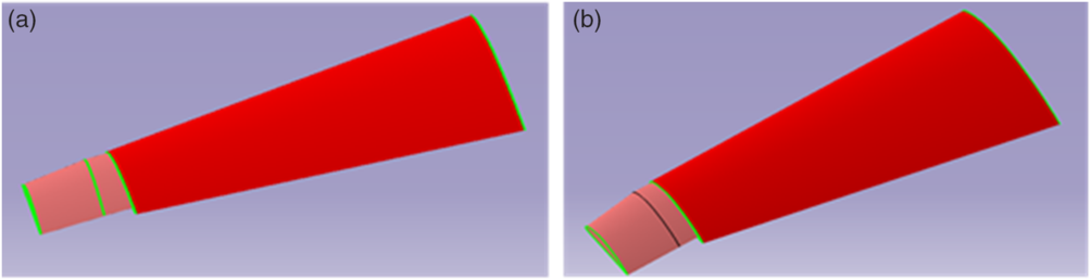
Both configurations of the wing are designed using Computer-Aided Design (CAD) with CATIA software and allow three various span extensions. Table 2 shows the wing geometries of their two configurations at the original position and for the specific span extension ${\rm{s}}$
.
${\rm{s}}$
.
3.0 AERODYNAMIC ANALYSIS
3.1 Aerodynamic wing studies using XFoil and ANSYS fluent
The aerodynamic investigation is performed in two steps. First, the 2-dimensional (2D) aerodynamic analysis used XFOIL code to obtain aerodynamic forces and moments coefficients as functions of Reynolds number (Re) and the angle-of-attack (AOA). The Vortex Lattice Method is used for numerical analysis based on XFLR5 code solver. The aerodynamic coefficients were conducted at various Reynolds numbers and angles of attack. The aerofoil was operated at Reynolds numbers of (610263, 1220525, 1830788, and 2441050 relatively to the chord), which correspond to speeds of 0.05, 0.10, 0.15, and 0.20 Mach. The selected angles of attack were ranged between −3° and 15°.
Moreover, the number of panels was 160, with the aim of obtaining more realistic results. The NACA 4412 includes four-digit code used to define the aerofoil by:
The first digit gives the maximum camber in terms of a percentage of the chord, more specifically 4% of the chord length.
The second digit gives the location of maximum camber from the aerofoil leading edge in 10’s of the chord percentage, such as 40% from the aerofoil leading-edge.
The third and fourth digits give the maximum thickness of the aerofoil in terms of percentage of the chord, such as 12% of the chord length(Reference Kevadiya and Vaidya31).
The NACA 4412 aerofoil geometrical shape is shown in Fig. 3.
Geometry of the NACA 4412 aerofoil.

Lift and drag coefficients variation versus the angle-of-attack.

The variation of lift and drag coefficients with the angle-of-attack are shown in Fig. 4; these variations were obtained by the use of the XFLR5 software which uses both Xfoil algorithms and the Vortex Lattice Method(Reference Deperrois32).
Once the aerodynamic characteristics for the NACA 4412 aerofoil have been analysed numerically in XFLR5 solver, the novel design concept for creating the span morphing wing was developed. The variable span morphing wing, proposed in this study, aims to benefit from the aerodynamic and structural advantages of tapered wing shape. The main benefits of tapered span design with respect to its baseline design wing might be, for example, better aerodynamic efficiency (lower drag and better lift distribution along its span), better structural efficiency (stronger and lighter) as the chords lengths are varying between the root and tip, and manoeuverability would be better. The lift to drag ratio efficiency influence by the taper ratio at the low flight speed(Reference Traub, Botero, Waghela, Callahan and Watson33).
Second, by the numerical investigations four versions (based on the wingspan extension stages) of Variable Span Morphing of Tapered Wings (VSMTW) are implemented by using a Computational Fluid Dynamics (CFD) ANSYS Fluent solver that is used as it can offer beneficial tools for geometry editing, meshing, simulation setup, and results of the analysis(Reference Liauzun34). The use of ANSYS Fluent solver provides accurate solutions and speeds up the simulations of complex scenarios such as transonic or turbulent flows. The results obtained from this numerical study will be analysed for the variable morphing wingspan experimental performance validation using a wind tunnel. In this comparative design study, the following procedure is performed for both sweep angle models(Reference Liauzun, Le Bihan, David, Joly and Paluch35,Reference Liauzun36) .
The geometrical shape and physical outlines of the design are determined using Computer-Aided Design (CAD) as represented in Fig. 2.
The data is then processed, and the fluid chamber volume (or fluid domain) is defined.
The fluid volume and the wing shape are divided into discrete cells (meshes). The number of elements and nodes is varied as the wing length change and in correlation with the wing geometrical shape. The physical modelling is selected based on the equations of fluid motions.
For the simulation, boundary conditions, such as fluid behaviour and properties (density, speeds, viscosity, pressure, etc.), must be defined.
To obtain the final solution, and to visualise the results, a postprocessor is used after solving the equations iteratively, which allows creating contour plots, vector plots, 2D and 3D surface plots, etc. Moreover, it can offer animation for dynamic results display.
Figure 5 shows the numerical analysis methods carried out in this study using ANSYS Fluent solver.
Numerical analysis phases using ANSYS Fluent.

The 3D unstructured tetrahedral mesh for both design shapes was employed for the flow around the model. For more accuracy, the “inflation layers” were applied to smooth the mesh of edges around the wing surface. Thus, the inflation layers provide a highly precise resolution of the boundary layer. The number of ten inflation layers was situated within the boundary layers to obtain the accurate solving of the boundary layer. The meshing method is described in Fig. 5(b). The two modelling methods based on the Reynolds-Averaged Navier-Stokes (RANS) were applied for computing the flow past the wing. First, by the k-ɛ turbulence model was used to simulate mean flow characteristics around the wing to investigate the turbulent flow conditions, because of the fact that the free-shear layer flows with relatively small pressure gradients. The k-epsilon model was based on two equations, and it provided the flow simulation, including its rotation, recirculation, and separation(Reference Grisval and Liauzun37). According to the results obtained with means of the k-ɛ model, two wing design shapes (with two sweep angles) were selected among their preliminary design shapes; thereafter, the Transition Shear-Stress Transport (Transition SST) turbulence model was implemented as it could predict correctly the flow separation, provide robust accurate results including steady-state solutions(Reference Langtry and Menter38,Reference Coughtrie, Borman and Sleigh39) . The Transition SST turbulence model was based on four equations and solves flow turbulence for smooth transition based on the k–Ω model near the wall. Transition SST turbulence model is rated for aerodynamic applications as one of the most precise model used for aerodynamic performance evaluation. Boundary condition, solution control parameters and material properties were defined.
Increase of wing span y/b (%).

3.2 Aerodynamic performance and mission range
To evaluate the performance improvements, the rolling moment, the roll rate, the range, and the endurance was calculated from the aerodynamic coefficients obtained using the morphing technique.
3.2.1 Rolling moment calculation
The adjustment of the variable-span wing asymmetrically is predicted to obtain rolling moment as given otherwise by conventional ailerons. However, the challenge of this technique is from the structural viewpoint; the root wing will be influenced by considerable sizeable bending moment(Reference Ajaj, Friswell, Saavedra Flores, Keane, Isikveren, Allegri and Adhikari40). The bending moment of a variable wingspan increases as the product of lift distribution, wing area, wing panel span, and free-stream dynamic pressure increases due to the span extension. Weight is also a critical factor for increasing the bending moment, especially when an added actuation system would be located at the wing root. According to some studies(Reference Ajaj, Friswell, Saavedra Flores, Little and Isikveren20), the root bending moment of a variable wingspan can be 60% higher than the root bending moment of conventional ailerons.
The semi-span of one side extends to the desired distance  ${y_1}\;$
while maintaining the other side fixed, as shown in Fig. 6.
${y_1}\;$
while maintaining the other side fixed, as shown in Fig. 6.
The total lift at the beginning of the roll motion can be determined as Ref. Reference Ajaj, Friswell, Saavedra Flores, Keane, Isikveren, Allegri and Adhikari40:
 \begin{align}L + \Delta L = q{C_L}\left( {S + \Delta S} \right)\end{align}
where L is the lift produced by the original wing, ∆L is the acquired lift due to span extension, q is the dynamic pressure, C Lis the lift coefficient, S is the original wing area, and ∆S is the additional wing area after span extension. The lift is equal on both sides of the wing due to its symmetric span. However, as the wing area changes on one side due to the asymmetric span extension or retraction, the lift will increase more on one side of the wing.
The area S of a tapered wing and the changing area ∆S of the swept angle geometrical shape of wing become:
 \begin{align}S = b\ast\frac{{\left[ {{c_r} + {c_t}} \right]}}{2}\end{align}
where b is the wingspan at the original wing, c r is the root chord, and c t is the tip chord.
The changing area is:
 \begin{align}\Delta S = \frac{{\left[ {{c_r} + {c_t}} \right]}}{2}\ast{y_1}\end{align}
where y 1 is the additional wingspan after span extension, c r is the root chord, and c t is the tip chord.
The total lift coefficient can be found with the following equation.
 \begin{align}{C_L} = \frac{{L + \Delta L}}{{q\ast\frac{{\left[ {{c_r}\, + \,{c_t}} \right]}}{2}\left( {b + {y_1}} \right)}}\end{align}
The rolling moment L roll can be approximated with the following equation(Reference Ajaj, Friswell, Saavedra Flores, Keane, Isikveren, Allegri and Adhikari40):
 \begin{align}{L_{roll}} \approx \Delta L\left( {\frac{b}{2} + \frac{{{y_1}}}{2}} \right) \approx q\ast\frac{{\left[ {{c_r} + {c_t}} \right]}}{2}{y_1}{C_L}\left( {\frac{b}{2} + \frac{{{y_1}}}{2}} \right)\end{align}
As the assumption of the equation, the lift influences in the midpoint of the wing extension, because of that, it has a total moment arm of ((b/2) + (y 1/2)). By substituting Equation (4) in the rolling moment Equation (5), the Equation (6) becomes:
 \begin{align}{L_{roll}} = \frac{{L + \Delta L}}{2}{y_1}\end{align}
where L roll is the rolling moment, L is the lift at the original position, and ∆L is the gained lift through span extension.
The Equation (6) shows that by extending the wing on one side, the rolling moment produced relies on the difference between a generated lift in both semi-span.
3.2.2 Roll rate
The asymmetric span configurations can vary the lift distribution in morphing wing. For example, when one side of the wing (starboard or port) extends its span longer than the other side of the wing, the lift distribution symmetry point will transfer to the long wingspan(Reference Nelson41). The generated roll moment is expected to be the one given by the deflection of conventional ailerons for roll manoeuvers control(Reference Ajaj, Friswell, Saavedra Flores, Keane, Isikveren, Allegri and Adhikari40). For the pure roll rate due to varying mass moment inertia, the first-order equation can be defined as Refs. Reference Beaverstock, Fincham, Friswell, Ajaj, De Breuker and Werter21 and Reference Ajaj, Friswell, Saavedra Flores, Keane, Isikveren, Allegri and Adhikari40:
 $${L_{roll}} = {I_{xx}}\dot{p} + p\dot{I}_{xx}$$
Where I xx is the mass moment of inertia around the x-axis and p is the roll rate. With the assumption of wing mass distribution, and neglection of the contribution of other components such as fuselage and empennage, the equation of mass moment of inertia becomes:
 $${I_{xx}} \approx {{{m_w}{b^2}} \over {12}}$$
where m w the mass of wing. The mass moment of inertia with variable-span wing can be expressed by:
 $${I_{x{x_s}}} = {I_{xx}} + {{{m_w}} \over 6}\left( {y_1^2 + y_2^2 + b{y_1} + b{y_2}} \right)$$
I xxs is a mass moment of inertia with variable-span wing around the x-axis, and y 1, y 2 are the extensions of starboard and port, respectively. In the previous equations, the mass moment of inertia of fuselage and empennage are neglected. Hence, the rate of alteration of the wing inertia is time-dependent and is defined as:
 $${\dot{I} _{{x_s}}} = {{{m_w}} \over 6}\left( {2{y_1}{{\dot y}_1} + 2{y_1}{{\dot y}_2} + b{{\dot y}_1} + b{{\dot y}_2}} \right)$$
Based on the Equation (7), the rolling moment equation for span morphing can be defined as Refs. Reference Ajaj, Friswell, Saavedra Flores, Keane, Isikveren, Allegri and Adhikari40 and Reference KÖrpe, Çetin, Altınok, Morasata, Eren, Demircan, Kidane, Demir, Usama and Kunnathur42:
 $${L_{roll}} = {I_{x{x_s}}}\dot p + p{\dot{I} _{x{x_s}}} = {{\partial L} \over {\partial {y_1}}}{y_1} + {{\partial L} \over {\partial {y_2}}}{y_2} + {{\partial L} \over {\partial p}}p$$
where  $\left( {\partial L/\partial {y_1}} \right){y_1} + \left( {\partial L/\partial {y_2}} \right){y_{2\;}}\;$
is the roll moment due to the extension of starboard and port, respectively, and
$\left( {\partial L/\partial {y_1}} \right){y_1} + \left( {\partial L/\partial {y_2}} \right){y_{2\;}}\;$
is the roll moment due to the extension of starboard and port, respectively, and  $\left( {\partial L/\partial p} \right)p\;$
is the roll damping moment. To alleviate the bending moment at the wing root, the appropriate extensions of both wing sides should be determined at a given flight condition(Reference KÖrpe, Çetin, Altınok, Morasata, Eren, Demircan, Kidane, Demir, Usama and Kunnathur42). Therefore, the governing equation of rolling motion becomes.
$\left( {\partial L/\partial p} \right)p\;$
is the roll damping moment. To alleviate the bending moment at the wing root, the appropriate extensions of both wing sides should be determined at a given flight condition(Reference KÖrpe, Çetin, Altınok, Morasata, Eren, Demircan, Kidane, Demir, Usama and Kunnathur42). Therefore, the governing equation of rolling motion becomes.
 $${I_{x{x_s}}}\dot p - \left( {{{\partial L} \over {\partial p}} - {{\dot{I} }_{x{x_s}}}} \right)p = {{\partial L} \over {\partial {y_1}}}{y_1} + {{\partial L} \over {\partial {y_2}}}{y_2}$$
where
 $${{\partial L} \over {\partial p}} = {{\rho V\bar c\left( {b + {y_1} + {y_2}} \right)} \over 4}{C_{{l_{ps}}}}$$
and
 \begin{align}{C_{{l_{ps}}}} = \frac{{\pi \left( {b + {y_1} + {y_2}} \right)}}{{3( {b + {y_1} + {y_2} + 2\bar{c}} )}}\end{align}
where the C lps is the rolling moment damping coefficient.
The steady roll rate is determined by:
 $${L_{{p_s}}} = {{\left( {{{\partial L} \over {\partial p}} - {{\dot{I} }_{x{x_s}}}} \right)} \over {{I_{xx}}}}$$
and
 \begin{align}{L_{\partial y}} = \frac{{\left( {\frac{{\partial L}}{{\partial {y_1}}} + \frac{{\partial L}}{{\partial {y_2}}}} \right)}}{{{I_{xx}}}}\end{align}
The time constant τ s is time for roll mode response.
where the time constant can be defined as:
 \begin{align}{\tau _s} = - \frac{{4{I_{x{x_s}}}}}{{\rho Vc{{\left( {b + {y_1} + {y_2}} \right)}^3}{C_{{l_{ps}}}}}}\end{align}
The steady state roll rate of the variable-span wing is Ref. Reference KÖrpe, Çetin, Altınok, Morasata, Eren, Demircan, Kidane, Demir, Usama and Kunnathur42:
 \begin{align}p_{ss}^{\ast} = - \frac{{\left( {\frac{{\partial L}}{{\partial {y_1}}} + \frac{{\partial L}}{{\partial {y_2}}}} \right)}}{{L_p^{\ast}}}\left( {\partial {y_1} - \partial {y_2}} \right)\end{align}
3.2.3 Improved range and endurance estimation
The efficiency of the morphing wing was also estimated in terms of range and endurance increases. As the wingspan extends, the aerodynamic performance (lift-to-drag) increases, thus increasing the range and endurance contribute to an improvement of aircraft efficiency. For the purpose of investigating the increase of performance, the geometrical characteristic of a real aircraft was considered.
The estimations were made using the characteristic of the UAS-S4(Reference Kuitche and Botez43–Reference Segui, Kuitche and Botez45). The UAS-S4 is an unmanned aerial system designed and manufactured by Hydra technologies for the military and civilian purpose (Fig. 7). Its general characteristics are presented in Table 3.
Hydra technologies UAS-S4 Ehecalt.

The characteristics of the UAS-S4

The increase of the aerodynamic efficiency for selected speeds from wing original position to its full span extension

The range and endurance of the UAS-S4, assuming steady level flight based on the Breguet formulas are(Reference John and Anderson46):
 \begin{align}R = \frac{\eta }{c}\frac{{{C_L}}}{{{C_D}}}\ln \frac{{{W_0}}}{{{W_1}}}\end{align}
 \begin{align}E = \frac{\eta }{c}\frac{{{C_L}^{3/2}}}{{{C_D}}}\frac{{\sqrt {2{\rho _\infty }S} }}{{\sqrt {{W_1}} - \sqrt {{W_0}} }}\end{align}
Where R and E are the range and endurance, η, c, W 0, and W 1, are the propulsive efficiency, the fuel consumption rate, takeoff weight, and landing weight, respectively. For a given morphing aircraft, in Equations (19) and (20), the values of airspeed and weight are constant.
Note that for a given altitude and weight, the range and endurance are maximised when the  ${{{C_L}} \over {{C_D}}}$
and
${{{C_L}} \over {{C_D}}}$
and  ${{{C_L}^{3/2}} \over {{C_D}}}$
are maximum(Reference Blondeau and Pines47). Their maximum values are given by the following equations:
${{{C_L}^{3/2}} \over {{C_D}}}$
are maximum(Reference Blondeau and Pines47). Their maximum values are given by the following equations:
 \begin{align}{\left( {\frac{{{C_L}}}{{{C_D}}}} \right)_{max}} = {\left( {\frac{{{C_{{D_0}}}\ast\pi \ast e\ \ast AR}}{{2\ast{C_{{D_0}}}}}} \right)^{1/2}}\end{align}
 \begin{align}{\left( {\frac{{{C_L}^{3/2}}}{{{C_D}}}} \right)_{max}} = {\left( {\frac{{3\ast{C_{{D_0}}}\ast\pi \ast\ e\ \ast\ AR}}{{4\ast{C_{{D_0}}}}}} \right)^{3/4}}\\[-20pt]\nonumber\end{align}
Where e is span efficiency factor, and C D0 is zero-lift drag coefficient.
The aerodynamic efficiency is dependent on the wing aspect ratio. As a result, an increase in wing aspect ratio would lead in the boost up of both flight range and endurance. Moreover, the flight endurance is further increased for a variable wing because the wing area also increases based on a change of aspect ratio.
4.0 PERFORMANCE EVALUATION OF DESIGNED MODELS
This comparative study gives an evaluation of the performance characteristics for selecting the best geometrical shape. The results obtained in this work include varying parameters obtained using Computational Fluid Dynamics (CFD) solver. The wings have been designed by considering advantages of the structural and aerodynamic design point of views. For accomplishing the simulation processes, the morphing wing span has been extended in this investigation by 25%, 50%, and 75% of the original wing. The analyses were carried out at four airspeed values, 17, 34, 51, and 68m/s, corresponding to Mach number values of 0.05, 0.10, 0.15, and 0.20, respectively. Furthermore, the air density and dynamic pressure were determined at various altitudes, such as at the sea level, at 5,000 and 10,000ft.
4.1 Comparison results obtained for aerodynamic efficiency
The results present the comparison of the aerodynamic efficiency variation for the various airspeeds, for which the length and the sweep angle of the inner section were varied. Figure 8 shows the variation of the lift coefficient with the drag coefficient (C L vs C D) changes substantially for the first and second sweep angle models (β = 4.5° and β = 8.9°), respectively, when both wingspan and speed vary (lift increase and drag decrease). However, as seen in Fig. 8, the aerodynamic performance generated by varying the wingspan length was more efficient than that generated by varying the speed at all selected altitudes in this investigation. For instance, the lift and drag coefficients obtained at sea level for the entire wing were equal to 0.350 and 0.0123 for the first sweep angle model, and were equal to 0.340 and 0.0122 for the second sweep angle model at low speed (Mach number of 0.05), and for full wingspan extension.
Drag coefficient versus lift coefficient of span extension at various velocities for (a) first sweep angle model and (b) second sweep angle model at sea level, 5,000ft., and 10,000ft.

On the other hand, the lift and drag coefficients at maximum speed (Mach number of 0.2) but the original position were of 0.362 and 0.0109, and of 0.352 and 0.0109 for the first and second sweep angle models, respectively.
Furthermore, the main parameters in this investigation are the sweep angle of the moving segment inside the fixed wing, the wingspan, and the flight speed variation. However, the effects of these two parameters (wingspan lengths and flight speeds variations) on the UAV wing are different for the two sweep angles models. For instance, it is evident that the increase of the wingspan length (at the same flight speed) can conduct, for example, to the increase of the lift coefficient at the cruise speed. Therefore, when the wing extended to 75% from its original length, for the first and the second sweep angle models, the lift coefficient increased up to 11% and up to 9.4%, respectively. It was noticed that the lift coefficient increases with the sweep angle decrease. Moreover, the drag coefficient decreased for the first and the second sweep angle models, up to 16.2% and up to 12.3%, respectively (it decreased with the decrease of the sweep angle).
On the other side, by taking into account the varying speed, for example, when the wingspan was at 75% of its length, and the speed varied from its minimum to its maximum value, the lift coefficient increased up to 3.6%, and 3.3% for the first and the second sweep angle model, respectively. The drag coefficient reduced to 12.7% and to 11.1%, respectively, for the first, and the second sweep angle models.
Figure 9 illustrates that the performances of the wing with the first sweep angle model (β = 4.5°) are more effective than the performances of the wing with the second sweep angle model (β = 8.9°).
Aerodynamic efficiency comparison at cruise and maximum speed at (a) the sea level, (b) at 5,000ft. and (c) 10,000ft.

The aerodynamic efficiency, for instance, increases with the full-extended span at the cruise speed and altitude 1,000ft for the first sweep angle configuration to 31.39, and the second sweep angle configuration to 30.57. Therefore, the improving ratio of aerodynamic efficiency for both configurations at this speed when span extends from its original position to its full extension was of 32.39% and 29.5%, respectively. For more details, Table 4 contains the values of aerodynamic efficiency for span configuration extension at selected speeds.
The results indicate that as the span increases, the aerodynamic efficiency increases. Figure 10 shows the drag coefficient versus the lift coefficient variations for the four morphing wing configurations at the sea level, at 5,000 and 10,000ft altitudes. As expected, changing from the original position to maximum span extension increases the lift coefficient, and decreases drag coefficient, therefore, the maximum lift coefficient increases, and the induced drag decreases. Since the angle-of-attack is constant at 0° in this investigation, therefore, the effect of angle-of-attack on the wing is out of scope for this study. Thus, the aerodynamic efficiency increases based on the influence of wingspan extension (0%, 25%, 50%, and 75%), and the variation of the speed (Mach numbers of 0.05, 0.10, 0.15, and 0.20) for two sweep angle models. The aerodynamic performance rate for each extended span decreases slightly for both configurations. For example, the aerodynamic performance rate differs in the first sweep angle configuration, at 10,000ft altitude and at the cruise speed when the span is extended from its original position to 25%, from 25% to 50%, and from 50% to 75% of its length to 11.70%, 9.92%, 7.61%, respectively. In the same way, as in the first sweep angle configuration, the aerodynamic performance rates for the second sweep angle configuration are 11.65%, 8.48%, and 7.33%, respectively. Table 5 contains all aerodynamic performance values for first sweep angle model and second sweep angle model at cruise and maximum speed. The induced drag average based on the full-extended span (from the original position to 75% of its length) decreased to approximately 7% for both shapes at all selected speeds.
The increasing rate of aerodynamic performance for the first and second sweep angle models when span length changes at cruise and maximum speeds

Drag coefficient versus lift coefficient variation at (a) the sea level, (b) at 5,000ft., and (c) at 10,000ft.

It is clear that the change of the position of the moving wing axis inside the fixed-wing noticeably influences the performance of the morphing wing. For instance, the difference in aerodynamic performance between the first and the second sweep angle configuration suggests that the difference in the improvement of performance between the first sweep angle and the second one reached up to 27.43%, 28.44%, and 28.81% for loiter, cruise, and max speed respectively, when wingspan is modified to full extended span.
4.2 Asymmetric span morphing at cruise and maximum velocity
As one of the benefits of a variable morphing wing, the roll control is accomplished by using different spanwise lift distribution between the port wing (PW) and the starboard wing (SBW). However, it is obvious that this technique is not the best method to achieve roll control due to the structural perspective because of the increasing of the bending moment at the wing root noticeably. Thus, the reinforcement of the wing structure must be taken into account in the mechanical design and optimisation to overcome the bending moment increase. The roll control must be calculated for the differential of span extension. Span retraction of varying extension rates (from 75% to original wing) is applied, where the rate of change is held constant from maximum to minimum. The results in Fig. 11 indicate that increasing span leads to delay in the roll rate while decreasing span tends to speed up the roll rate Equation (18) as shown in Fig. 11 for both altitudes of 5,000 and 10,000ft. On the contrary, Fig. 12 illustrates that the roll damping moment increases as the wingspan increases.
Roll rate versus the wingspan locations for the first and second sweep angles model (a) at 5,000ft. and (b) 10,000ft.

Rolling moment damping coefficient for the first and second Model PW: port wing, SBW: starboard wing.

Rolling moment coefficient versus wingspan locations for the first and second sweep angle models (a) at 5,000ft. and (b) 10,000ft.

Time constant versus wingspan locations calculated for the first and second sweep angle model.

(a) Endurance and (b) range versus wingspan variation for first sweep angle model and second sweep angle model at loiter velocity.

The roll rate increases significantly as the speed increases. As the flight speed increases, the tendency of the aircraft reduces to roll, as the damping increases, which is very consistent with the rolling moment damping coefficient. The purpose of this study is to compare two design options for selecting the best shape in terms of the performance of three characteristics (aerodynamic, roll control, and range and endurance). The results of the rolling moment damping coefficient Equations (13) and (14), are shown in Fig. 12, indicate that the first sweep angle generates a more rolling moment as the span increases. Nevertheless, the changing of the rolling moment is about 2.8 % at full span extension.
It can be summarised that the asymmetrical variable span can be used for rolling control, and it can achieve steady turns. Since generating the lift distribution is different for the first and the second sweep angle model in the present case, the rolling moment coefficient is slightly larger for the first sweep angle model as shown in Fig. 13. The time constant of roll mode response is identical for both sweep angles models as the parameters in Equation (17) are constant. Figure 14 refers to the time response of both variable morphing span wing models for roll control at the altitudes of 5,000 and 10,000ft. The rolling time constant increases with the wings span location, as seen on Fig. 14.
4.3 Comparison results for the range and the endurance
The results provide a clear image of the benefits of a variable morphing wing for range and flight endurance. This investigation indicates that the increase of the flight range and endurance due to wingspan extension influences on all selected speeds considerably. For instance, Fig. 15 represents the significant improvement of the range and endurance metrics for loitering velocities at 5,000 and 10,000ft.
The assessment of the increased endurance and range is based on the change of the  ${{{C_L}} \over {{C_D}}}$
and
${{{C_L}} \over {{C_D}}}$
and  ${{{C_L}^{3/2}} \over {{C_D}}}$
ratios. The total drag computed for morphing wingspan is a combination of the induced drag and zero lift drag. As shown in Fig. 15, the wing span area of the wing has an important influence on the endurance and drag. Furthermore, Fig. 15 shows that the induced drag decreases when the wingspan extends, while the opposite occurs when the wingspan extends the zero lift drag increases. The maximum extension of the flight range to 5,000ft is up to 46.89% for the first sweep angle model and 43.16% for the second sweep angle model when the span extends from its original length to its full extension. The same pattern is found at the altitude of 10,000ft, where the flight range is up to 43.94% for the first sweep angle model, and is up to 41.31% for the second sweep angle model. Therefore, the first sweep angle model improves the flight range at the altitude of 5,000ft by 8.64%, and by 6.37% at the altitude of 10,000ft with respect to the second sweep angle model.
${{{C_L}^{3/2}} \over {{C_D}}}$
ratios. The total drag computed for morphing wingspan is a combination of the induced drag and zero lift drag. As shown in Fig. 15, the wing span area of the wing has an important influence on the endurance and drag. Furthermore, Fig. 15 shows that the induced drag decreases when the wingspan extends, while the opposite occurs when the wingspan extends the zero lift drag increases. The maximum extension of the flight range to 5,000ft is up to 46.89% for the first sweep angle model and 43.16% for the second sweep angle model when the span extends from its original length to its full extension. The same pattern is found at the altitude of 10,000ft, where the flight range is up to 43.94% for the first sweep angle model, and is up to 41.31% for the second sweep angle model. Therefore, the first sweep angle model improves the flight range at the altitude of 5,000ft by 8.64%, and by 6.37% at the altitude of 10,000ft with respect to the second sweep angle model.
5.0 CONCLUSIONS AND FUTURE WORK
A variable morphing wingspan is an effective technology for enhancing aerodynamic efficiency and replacing conventional control surfaces. The improvement of flight performance leads to an increase in the flight range and endurance for a given flight. The purpose of this comparative study was to implement the analysis and the examination of three key characteristics using aerodynamics solver.
The major findings of this investigation resided in the fact that the variable span-morphing of the tapered wing can deliver the required improvements of performance because of the variation of wingspan extension, and sweep angle variation. However, estimated weight increases due to an equivalent stiffness of the structure and actuation system in comparison with the conventional wing. “In addition, flutter parameters (speed, damping) might change as they are sensitive to wingspan elasticity increase during the flight envelope. The aeroelastic parameters would also change depending on the motion of the moving segment (extension or retraction), and these changes should be taken into account in the wing design and optimisation process.” The obtained results show the significant improvement in aerodynamic performance (for instance, at the cruise phase) by 32.39% for the first sweep angle model, and by 29.5% for the second sweep angle model. The rolling moment is sensitive to the lift distribution generated by span extension. The roll rate of variable wingspan decreases when the flight speed increases. The varying moment generated by variation of wingspan extension between the port and starboard wings suggests that the wing structures must be designed by taking into account the bending moment impacts at the wing root. The main advantages of variable morphing wingspan are the drag reduction; therefore, increase of range flight and endurance. The findings show that around 43.94% and 41.31% increase in flight range for the first and second sweep angle model can be achieved when the full wing extension is used.
Finally, it has been inferred that for future work, the best design shape of the variable morphing wing is the first sweep angle model. It is clear that for aerodynamic efficiency, the first sweep angle model is more efficient than the second sweep angle model for all speeds. For instance, at the cruise speed, the incremented ratio from the original position to 75% extension of its original length for the first and the second sweep angle models were of 32.39% and 29.5%, respectively, which corresponded to the difference in the aerodynamic performance improvement between the two models of 9.34%. However, the efficiency of the rolling moment reduces to 2.5%. Regarding the range and endurance of flight, the first sweep angle model is 8.6% better than the second sweep angle model.
To accomplish the primary objective, several steps will be taken in future work. Additional analysis phases will be carried out for the stability and control derivatives. The variable tapered span-morphing wing structure and mechanism integration will be tested together. Numerical optimisation topology techniques will be generated to examine compliant adaptive wing structures for reducing the wing weight.



