


Introduction
Circularly polarized antennas are critical for high-performance and low-loss antenna applications, such as uncompressed high-definition media transfers, sensing systems, and long-range high-resolution radar systems [Reference Cheng, Guo and Liu1]. Circularly polarized antennas, offering desirable advantages such as flexibility, mobility, weather penetration, and reduction in multipath reflections in transmission and reception, will be employed more widely in these systems [Reference Bai, Qu, Yang, Hu and Nie2]. A waveguide slot antenna demonstrates the merits of high efficiency, low cost, and flexible mechanical assembly. To improve the operating bandwidth and radiation efficiency, the patch is covered on the waveguide slot antenna in [Reference Xu, Wang, Huang and Wu3], but the axial ratio bandwidth (ARBW) <3 dB is only 3%. In [Reference Keivaan, Oraizi and Amini4, Reference Ferrando-Rocher, Herranz-Herruzo, Valero-Nogueira and Rodrigo5], parasitic dipoles are placed above the gap to achieve circular polarization (CP). A major difference between [Reference Keivaan, Oraizi and Amini4] and [Reference Ferrando-Rocher, Herranz-Herruzo, Valero-Nogueira and Rodrigo5] is that in [Reference Ferrando-Rocher, Herranz-Herruzo, Valero-Nogueira and Rodrigo5] three parasitic patches are placed on the substrate waveguide. The antenna in [Reference Lu, Jiao, Weng, Zhang and Cui6] consists of a pair of loops fed by a slot and two square patches are added on the opposite corners of both loops to implement CP. In [Reference Bai, Qu and Chan7, Reference Zhao and Luk8], an antenna is filled with a dielectric material in the waveguide. The impedance bandwidth (IBW) and ARBW performance of the antenna can be effectively improved. However, the substrate loss will become worse with the increase in frequency and expansion of the array. The authors in [Reference Al Sharkawy and Kishk9] used a combination of slots with different lengths to expand the IBW and ARBW of the antenna, achieving a 21% wider ARBW, and a lower gain with seven elements. In [Reference Chen, Wu, Wan, Li and Jin10], a circular polarizer is added to each slot of a waveguide slot antenna with a CP bandwidth of 2%. In [Reference Wu, Yang, Xu and Zhou11], CP is realized by combining two orthogonal linear polarizations, which are generated by two pairs of radiation slots on a cavity surface. However, the ARBW of the antenna is only 1.2%. The circular polarizer is fed by a slot, but the ARBW is narrow in [Reference Wang, Zhu and Gao12–Reference Gharibi and Hodjatkashani14].
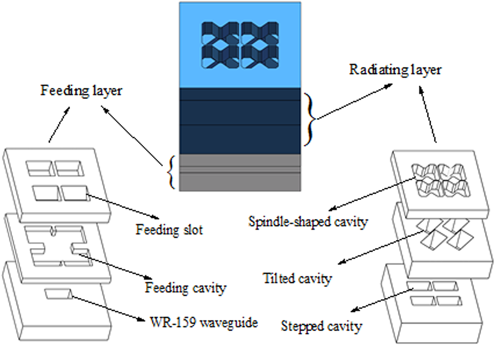
In this paper, we designed a wide-axis ratio antenna that can achieve CP. The antenna is an all-metal structure, which is relatively simple to process and of low cost. The adopted coupling cavity with a twisted waveguide effectively improves the CP axis ratio performance of the antenna. The three-dimensional model of the antenna is shown in Fig. 1.
Configuration of the proposed coupling cavity 2 × 2 CP array antenna.
CP unit cell design
In [Reference Xu, Li, Qi, Guangwei and Yang15], a microstrip circularly polarized antenna is designed. The rectangular strips form an orthogonal current with a 90° time shift on the surface of the antenna. The structure composed of two symmetrical square-coupling cavities is designed in this paper, which can form an electric field with a 90° time shifted. The unit is shown in Fig. 2. A symmetric square-coupling cavity is placed on a waveguide (F l × Fs) and excited. The operating principle of the CP antenna is that two orthogonal electric field modes with equal amplitude but a phase shift of 90° can be obtained [Reference Hesari and Bornemann16]. The symmetric square-coupling cavity is connected by two square-coupling cavities, as shown in Fig. 2(a). However, the size of the configuration will not make the distance between the array elements less than one wavelength. The corners of the symmetrical square-coupling cavity are cut to improve the compactness of the antenna. Figure 2(b) shows a spindle-shaped coupling cavity. The comparison simulated results of S 11 and AR of the two structures are shown in Fig. 6.
Views of the proposed unit cell: (a) symmetric square-coupling cavity and (b) spindle-shaped cavity (L 1 = 9.16 mm, L 2 = 20 mm).

The electric field of the waveguide is coupled to the symmetric square-coupling cavity, where it is decomposed into orthogonal electric fields with the same amplitude and 90° phase shift. Figure 3 shows the electric field of the unit cell operating at 5.8 GHz. The electric field density on the surface of the antenna for different phases of excitation field is simulated. When the phase of the excitation vector is 0° or 180° and 90° or 270°, which gives rise to radiation of waves polarized along the x-axis and y-axis and obtain the right-handed circularly polarized (RHCP) electric field.
Electric field distributions of the coupling slots at 5.8 GHz.

To demonstrate the effects of these parameters, we analyzed the axial ratio (AR) of the antenna with different values of Lr and Ls. The dependences of the AR on the different values at the lower frequency band and the higher frequency band are presented in Figs 4(a) and 4(b), respectively. If the value of Lr is <0.6λ 0 (where λ 0 is the free-space wavelength at 5.8 GHz), the AR curve will be shifted. The AR performance will become worse when the value of Lr is more than 0.6λ 0. The best value for the CP axis ratio performance is Ls = 0.4λ 0. When the sum of Lr and Ls is λ 0, the best CP axis ratio performance can be obtained. The ARBW of 14.6% can be achieved by the unit. Figure 6 shows the S 11 and AR curves of two coupling cavities. It is found by comparison that the performance of the spindle-shaped coupling cavity is preferable.
Simulation of the Lr and Ls: (a) AR for different values of Lr and (b) AR for different values of Ls.

2 × 2 Array antenna design
Feeding and coupling layer design
The feeding design of the antenna adopts the same method as [Reference Shad and Mehrpouyan17], and the structural parameters are shown in Table 1. If the distance between the antenna elements is less than one wavelength, the antenna sidelobe level will decrease [Reference Chu, Li and Guo18]. Note that the distance between the feeding slots should accommodate four subarrays next to each other, while being compact enough to ensure proper spacing for the radiating slots to avoid a high grating lobes’ effect. The distance between the array elements is more than λ 0 if the spindle-shaped coupling cavity is directly excited by the feeding port.
Optimized parameters of the array antenna

The antenna adopts a combined structure of stepped design and tilted design as shown in Fig. 5. The size of the tilted waveguide is T l × Tw twisted by 45°, which decomposes the electric field into horizontal and vertical components. The electric field is further decomposed to obtain an orthogonal electric field with equal amplitude and 90° phase shift in the spindle-shaped cavity. A comparison with the former result is shown in Fig. 6. The AR is expanded to 17%.
Spindle-shaped cavity with tilted waveguide.

Simulated with different cavities: (a) S 11 and (b) AR.

Array antenna design
Two parts constitute the antenna, including the feeding layer and the coupling layer. As shown in Fig. 1, four radiating elements in free space are positioned symmetrically in free space in the x- and y-directions. The distances between the coupling cavities are Fs and S 1. Figures 7 and 8 show the whole configuration of the multistep profile. The red dotted lines at the corners of the four cavities show the exact position of each radiating element relative to the groove in the center of the cavity. The overall structure is shown in Fig. 7. The stepped design and tilted design make the antenna more compact on the y-axis. The offset of the stepped layer is S 2. The feeding port and the stepped layer are connected by chamfering to improve impedance matching, as shown in Fig. 7(b). The sidelobe level of the E side is below −12.65 dB, and the minimum sidelobe level of the H side can attain −15.54 dB.
(a) Views of the feeding layer. (b) Views of the chamfering.

Multi-stepped configuration of the antenna.

Simulated and measured results
To verify the design, the 2 × 2 element antenna array was fabricated as shown in Fig. 9. The curve in Fig. 10 shows the measured and simulated S 11 and AR curves: the CP AR is below 3 dB at 5.41–6.02 GHz. Due to the mutual interference between the array elements, the ARBW of the CP array antenna is only 10.6%. As shown, the measurement and simulation results agree quite well with only a slight shift due to the fabrication tolerances.
Fabrication of the antenna.

Simulated and measured results: (a) S 11 and (b) AR.

Each element of the antenna radiates evenly. Compared with a traditional waveguide slot array antenna, the beam of the antenna is always in the normal phase [Reference Wang, Zhang, He, Chen and Yang19]. The simulated RHCP and left-hand circularly polarization patterns of 5.5, 5.7, and 5.9 GHz in the E- and H-planes are shown in Fig. 12. The radiation patterns of 5.5, 5.7, and 5.9 GHz in the E- and H-planes are shown in Fig. 11. The sidelobe levels of the antenna measured on the E-plane are −12.7, −12.65, and −13.05 dB; on the H-plane, the sidelobe levels are −15.54, 14.05, and−13 dB due to the large distance between the array elements. It can be seen from Fig. 12 that the measured antenna-radiating efficiency is above 80% in the working bandwidth. The maximum antenna gain can attain 15.65 dBi.
Simulated and measured radiation patterns in the E- and H-planes: (a) E-plane at 5.5 GHz, (b) H-plane at 5.5 GHz, (c) E-plane at 5.7 GHz, (d) H-plane at 5.7 GHz, (e) E-plane at 5.9 GHz, and (f) H-plane at 5.9 GHz.

Efficiency and gain of the array antenna.

The asymmetric structure would increase the loss of the antenna, the insertion loss of each port is 6.08 dB at 5.8 GHz. Compared with the traditional waveguide slot antenna, the antenna has a wider ARBW. This antenna has lower loss compared to the substrate waveguide slot antenna. In [Reference Lu, Gu, Wang, Liu and Lu20], the length of the circular polarizer is λ 0, while the length of the cavity proposed in this paper is only 0.36λ 0. Table 2 shows a comparison with the performances of the antennas in several literature studies.
Comparison with some previous works

Conclusion
In this paper, a circularly polarized 2 × 2 array antenna based on a spindle-shaped radiation cavity is proposed. The antenna has the advantages of high efficiency, wide ARBW, and low cost. The comparison of the three design methods demonstrates that adding the tilted waveguide can effectively improve the ARBW of the antenna to enhance the CP characteristics. Finally, the new CP antenna adopts the stepped design and the tilted design, which have wide IBW and ARBW as well as a good gain.
 Hai Wang received his BS degree from Logistical Engineering University, Chongqing, China, in 2015. He is currently working at PLA Strategic Support Information Engineering University pursuing his MS degree. His main research interests include aperture antennas, wideband antennas, and wide axial ratio antennas.
 Xue Lei received her BS and MS degrees from PLA Strategic Support Information Engineering University, Zhengzhou, China, in 1989 and 2000, respectively. She is currently working at PLA Strategic Support Information Engineering University. Her main research interests include antennas and propagation.
 Tiandong Duan received his BS and MS degrees from the Army Engineering University of PLA, Nanjing, China, in 1989 and 2000, respectively. He is currently working at PLA Strategic Support Information Engineering University. His main research interests include signal processing.
 Tianpeng Li received his BS and MS degrees from Air Force Engineering University, Xi'an, China, in 2012 and 2016, respectively. He is currently working at PLA Strategic Support Information Engineering University. His main research interests include antennas and propagation.
 Jun Gao received his BS degree from PLA Strategic Support Information Engineering University, Zhengzhou, China, in 2015. His main research interests include aperture antennas, high-gain antennas, and beam-steering antennas.
 Mingyang Zhao obtained his bachelor degree in electromagnetic field and microwave technology from the University of Information Engineering in 2013, and is currently studying for a Ph.D. in Information and Communication Engineering. His current research interests include phased arrays, antenna array synthesis, and optimization algorithms.


 Open access