


1 Introduction
Coherent beam combining (CBC) is one of the most prevailing techniques to break through the physical limitations of single laser[ Reference Fathi, Närhi and Gumenyuk1– Reference Jiang, Wu, An, Hou, Chang, Huang, Li, Su and Zhou4], which enables advanced applications such as gravitational-wave detection[ Reference Steinke, Tünnermann, Kuhn, Theeg, Karow, Varona, Jahn, Booker, Neumann, Weßels and Kracht5, Reference Zhang, Zhang, Zhang, Fu, Wang and Qiu6], space-debris removal[ Reference Esmiller, Jacquelard, Eckel and Wnuk7] and laser particle accelerators[ Reference Mourou, Brocklesby, Tajima and Limpert8, Reference Zhang, Zhang, Pang, Wang, Chen and Bao9]. Generally, CBC has been categorized into two schemes: filled aperture[ Reference Müller, Aleshire, Buldt, Stark, Grebing, Klenke and Limpert10] and tiled aperture[ Reference Fsaifes, Daniault, Bellanger, Veinhard, Bourderionnet, Larat, Lallier, Durand, Brignon and Chanteloup11]. Tiled-aperture CBC is able to form an optical phased array, enabling unique capabilities of beam steering and beam shaping, which can counter the adverse impact of atmospheric turbulence and thermal blooming[ Reference Weyrauch, Vorontsov, Mangano, Ovchinnikov, Bricker, Polnau and Rostov12, Reference Spencer and Brennan13]. However, combining efficiency in the tiled-aperture configuration is limited to less than 70% by sidelobes in the diffraction patterns[ Reference Fsaifes, Daniault, Bellanger, Veinhard, Bourderionnet, Larat, Lallier, Durand, Brignon and Chanteloup11, Reference Flores, Pulford, Robin, Lu and Shay14– Reference Ma, Chang, Ma, Su, Qi, Wu, Li, Long, Lai, Chang, Hou, Zhou and Zhou16]. For filled-aperture CBC, a theoretical combining efficiency of 100% can be achieved[ Reference Müller, Aleshire, Klenke, Haddad, Légaré, Tünnermann and Limpert17– Reference Tao, Si, Ma, Zhou and Liu20]. Nevertheless, spatially overlapped fields are not conducive for beam steering, which relies on extra optics, such as fast-tilt and deformable mirrors, to manipulate the combined beam[ Reference Xu, Ge, Hu, Zhang, Wang, Wu, Zhu and Hu21, Reference Liu, Di, Zhang, Ren, Di and Zhao22]. The multi-plane light conversion (MPLC) technique is a novel optical device to perform a unitary optical transformation[ Reference Morizur, Nicholls, Jian, Armstrong, Treps, Hage, Hsu, Bowen, Janousek and Bachor23], and has been demonstrated in CBC as well[ Reference Billaud, Gomez, Allioux, Laurenchet, Jian, Pinel and Labroille24], which combines the benefits of both tiled-aperture and filled-aperture schemes – sidelobe-free combination and beam manipulating capability for mitigating atmospheric turbulence effects[ Reference Demur, Leviandier, Turpin, Bourderionnet and Lallier25– Reference Billaud, Reeves, Orieux, Friew, Gomez, Bernard, Michel, Allioux, Poliak, Calvo and Pinel27]. As of 2023, up to 12 lasers have already been coherently combined using the MPLC technique[ Reference Demur, Leviandier, Turpin, Bourderionnet and Lallier25, Reference Demur, Turpin, Leviandier, Bourderionnet and Lallier28], which revealed that more channels require higher spatial dimensions and a larger number of phase planes, making the MPLC device more complicated and less feasibly manufactured[ Reference Kupianskyi, Horsley and Phillips29]. However, little theoretical or numerical work in the field of CBC by MPLC has been carried out, and the features, potentials and limitations have not been comprehensively investigated.
In this paper, a numerical model of CBC by MPLC has been built, which employed the modified wavefront matching algorithm for phase mask optimization. Firstly, the fundamental concept and system setup are briefly introduced, followed by the establishment and application of the numerical optical model. Comprehensive parameter analysis is then conducted to optimize the combining performance, where various parameters are swept and investigated in detail. Subsequently, the channel scalability has been discussed with different parameter strategies, demonstrating CBC of 1027 lasers with high efficiency and excellent beam quality using only seven phase planes. Furthermore, beam steering is investigated with MPLCs supporting different numbers of modes, which shows great advantages of power concentration over traditional tiled-aperture CBC. These results can shed light on designing laser systems based on the MPLC-CBC scheme.
2 Numerical model
A typical structure of a high-power CBC laser system based on MPLC is illustrated in Figure 1. The seed laser splits into multiple channels via a beam splitter (BS) with each channel propagating through a phase modulator (PM) and a multi-stage amplifier chain in sequence. The amplified high-power lasers are delivered into free space by a densely tiled collimator (CO) array[ Reference Li, Liao, Gao, Sun, Tan, Wang and Lan30], and then projected into the MPLC device. Generally, the MPLC device contains several phase masks spaced at a constant distance. Finally, a small fraction of the combined laser from the MPLC is sampled and collected by a photodetector, and the detected signal is then fed into the phase controller, which generates control signals through different algorithms to drive PMs to adjust laser phases[ Reference Demur, Leviandier, Turpin, Bourderionnet and Lallier25]. With phase-locking being implemented, the input laser array is transformed into a single, sidelobe-free laser beam, thereby achieving CBC.
Diagram of high-power CBC laser systems by MPLC.

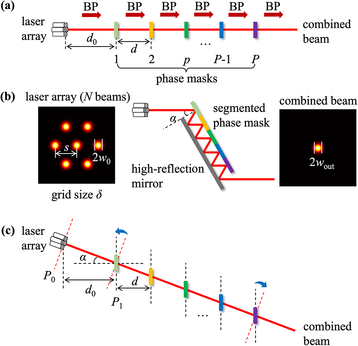
For a typical CBC laser system based on MPLC, optical parameters can be categorized into laser array parameters and MPLC device parameters, which are listed in Table 1. To illustrate these parameters clearly, all of them are shown in Figure 2. Here, seven beams arranged in a hexagon shape are taken as an example, and other shapes of array arrangement can also be employed in MPLC CBC[ Reference Billaud, Gomez, Allioux, Laurenchet, Jian, Pinel and Labroille24]. In the following numerical simulations, transverse space has been discretized in x/y coordinates with grid size δ, where smaller δ represents better spatial resolution. In Figure 2(a), the part showing laser propagation from the CO array to the combined output laser is replotted with the key optical parameters labeled, where BP represents free-space beam propagation. For compactness and high-power operation, the MPLC device is generally fabricated with reflective optic components, as shown in Figure 2(b), where the colored plate represents a segmented reflective phase mask while the other parallel plate in the gray color is a high-reflectivity mirror[ Reference Zhang and Fontaine31]. When the zigzag optical path in the compact MPLC in Figure 2(b) is unfolded, the equivalent optical path transforms into that shown in Figure 2(c), which is similar to the setup in Figure 2(a) except for a non-zero incident angle α.
Main parameters of the MPLC-CBC system.

Physical model of MPLC-based CBC. (a) Basic structure of MPLC. (b) Schematic diagram of the laser array, folded MPLC and combined beam. (c) Equivalent beam propagation path in a folded MPLC.

2.1 Input laser array
Because high-power fiber lasers with near-diffraction-limited beam quality are generally employed in CBC applications[ Reference Redmond, Ripin, Yu, Augst, Fan, Thielen, Rothenberg and Goodno32], the laser array at the source plane consisting of N sub-lasers was assumed to be a fundamental Gaussian beam array with pure linear polarization in the same direction. For simplicity, beam characteristics such as the amplitude, beam size and wave vector are assumed to be identical for each sub-laser except for the transverse position and optical phase. The electric field of the input laser array can be expressed by
 $$\begin{align}{E}_\mathrm{in}\left(x,y\right)=\sum \limits_{n=1}^N{Ae}^{i{\varphi}_n}\exp \left[-\frac{{\left(x-{x}_n\right)}^2+{\left(y-{y}_n\right)}^2}{w_0^2}\right],\end{align}$$
where A and (x, y) are the amplitude and transverse position, respectively, and (xn , yn ) and φn represent the central position and optical phase, respectively, of the nth beamlet.
It is important to note that the present numerical investigation mainly focuses on the ideal performance and design principles of the MPLC-based CBC system, which assumes perfect optical alignment and identical, aberration-free input beamlets. In a practical system, deviations from these ideal conditions, such as misalignment between the laser array and the MPLC optic, manufacturing errors in the phase masks and phase/amplitude noise from the laser amplifiers, will deteriorate the performance. The analysis of various error tolerances, which is crucial for engineering practice, is beyond the scope of this paper and will be investigated in future work.
2.2 Beam propagation
As shown in Figure 2, MPLC is composed of several phase masks with constant spacing, so the numerical propagation of the optical field between phase masks is fundamental. The propagation model differs for normal-incidence and non-normal-incidence configurations. For the folded MPLC with a non-zero incident angle α, the equivalent unfolded optical path is illustrated in Figure 2(c). The simulation follows this specific sequence.
-
(1) Initial field rotation: the input field, defined on the plane perpendicular to the propagation direction (P 0 in Figure 2(c)), is projected onto the tilted plane parallel to the phase masks (P 1 in Figure 2(c)) using a Fourier-domain coordinate rotation method[ Reference Matsushima and Matsushima33].
-
(2) Propagation between masks: the field is then modulated by the phase mask and propagated to the next phase mask plane. Because the phase masks are parallel but laterally shifted, this off-axis propagation is simulated using the translated plane angular spectrum method[ Reference Son and Oh34].
-
(3) Final field rotation: after the modulation by the last phase mask, the resulting field is rotated back from the tilted phase mask plane to a plane perpendicular to the output propagation direction for analysis.
To facilitate understanding of the simulation process, two blue arrows in Figure 2(c) illustrate the optical field rotations in steps (1) and (3). This approach efficiently models the zigzag path of the folded MPLC. For the normal-incidence case (α = 0), the method in step (2) simplifies to the classical angular spectrum method[ Reference Zhang and Fontaine31, Reference Barré and Jesacher35, Reference Tao, Huang, Zhou, Si and Liu36], and the rotation transforms in steps (1) and (3) are omitted.
The transverse phase profile of the pth plane is represented by $\Phi$
p
, so the phase modulation is exp(i
$\Phi$
p
, so the phase modulation is exp(i $\Phi$
p
) correspondingly. With these definitions, the output beam of an MPLC device can be numerically calculated through consecutive phase modulations and free space propagations. By inverting the forward procedure (using the conjugate of the propagation formula and phase modulation exp(i
$\Phi$
p
) correspondingly. With these definitions, the output beam of an MPLC device can be numerically calculated through consecutive phase modulations and free space propagations. By inverting the forward procedure (using the conjugate of the propagation formula and phase modulation exp(i $\Phi$
p
)), backward propagation from the MPLC output plane to the input plane can be readily accomplished.
$\Phi$
p
)), backward propagation from the MPLC output plane to the input plane can be readily accomplished.
2.3 MPLC design
MPLC is designed to perform unitary transformations, typically converting one set of orthogonal modes to another[ Reference Fontaine, Carpenter, Gross, Leon-Saval, Jung, Richardson and Amezcua-Correa37]. In traditional telecommunications multiplexing, this involves a one-to-one mapping between input channels and orthogonal output modes, which is designed for minimal crosstalk to ensure channel isolation[ Reference Fontaine, Ryf, Chen, Neilson, Kim and Carpenter38]. In contrast, a distinct many-to-one mapping strategy is employed in CBC scenarios. Here, all phase-locked input channels are engineered to coherently interfere into a single output mode (e.g., fundamental Gaussian mode), aiming for optimal combining efficiency and beam quality. Moreover, multiple output modes (e.g., high-order Laguerre–Gaussian (LG) modes) can be achieved by employing a proper phase coding method. In other words, a laser array with different phase codes is designed to generate different modes, utilizing the total laser energy for one output at a time while maintaining a many-to-one mapping.
Calculating the phase masks from input and output modes is a non-intuitive inverse design problem that typically requires iterative optimization methods. Among the available methods, the modified wavefront matching algorithm[ Reference Sakamaki, Saida, Hashimoto and Takahashi39] is commonly employed due to its efficiency. This algorithm converges rapidly via gradient descent, and is straightforward to implement, as no cost function is explicitly required. The process of phase mask design is outlined in Figure 3. Firstly, the input modes, output modes and MPLC parameters are defined. Subsequently, the input fields, output fields and phase masks are initialized, and the iterative process begins. After each iteration step, convergence is judged based on two criteria: whether the increase in coupling efficiency over the last five steps is less than 0.01%, or whether the maximum iteration count of 100 is reached. The process terminates if either criterion is met.
Process of phase mask design by wavefront matching.

Because multiple modes may be involved in MPLC, and each of them must be characterized individually, the subscript pair pm is used to denote the mth mode at the pth plane. Here, the total number of modes is denoted as M. To describe the wavefront matching process, additional superscripts f and b are employed to refer to the optical fields propagating in the forward and backward directions, respectively. At any given plane, the optical field is defined before phase modulation, regardless of its propagation direction. As an example, for a specific pair of input mode (E f pm ) and output mode (E b pm ), the mth input mode is propagated forward while the desired mth output mode is propagated backward to the pth plane. The phase mask at the pth plane is then updated based on the overlap field of these two counter-propagating wavefronts. For M input and output mode pairs, the phase update is averaged over all mode pairs to ensure each mode evolves fairly into its desired output mode.
3 Coherent beam combining optimization and parameter analysis
As outlined in Section 2, an MPLC-based CBC system involves many parameters, whose influence on combining performance requires systematic evaluation. For CBC applications, evaluation metrics such as power in the bucket (PIB) and transmitted power have been employed widely[ Reference Jabczynski and Gontar40]. However, these metrics are not suitable for CBC by MPLC. On the one hand, it is difficult to define a far-field bucket as in tiled-aperture CBC since the sidelobes are eliminated[ Reference Limery, Lombard, Bourdon, Billaud, Pinel, Labroille, Guennic and Jian26]. On the other hand, the total power is transmitted to the output, with no power leaking out from other ports of the combiner, which differs from common filled-aperture CBC[ Reference Billaud, Gomez, Allioux, Laurenchet, Jian, Pinel and Labroille24], so combining efficiency defined by transmitted power is not suitable either. Therefore, inspired by Ref. [Reference An, Huang, Li, Leng, Yang and Zhou41], the coupling efficiency η is introduced to evaluate the combining performance. It quantifies the power overlap between the actual field E 2 and the desired field E 1 (e.g., fundamental Gaussian mode), and is defined as follows:
 $$\begin{align}\eta =\frac{{\left|\iint {E}_1^{\ast }{E}_2 \mathrm{d}x\mathrm{d}y\right|}^2}{\iint {\left|{E}_1\right|}^2 \mathrm{d}x\mathrm{d}y\iint {\left|{E}_2\right|}^2 \mathrm{d}x\mathrm{d}y}.\end{align}$$
The value of η falls in the range between 0 and 1, where larger η represents better similarity between the two modes. Hereafter, η is referred to simply as efficiency. Meanwhile, since the target beam profile is a Gaussian one, the M 2 factor is also employed to evaluate the beam quality[ Reference Siegman and Dowley42].
3.1 Initial demonstration
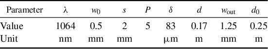
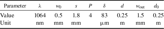
To establish a performance baseline, we begin with a functional but suboptimal configuration, where parameter variations will produce discernible changes in the combined beam, thereby illuminating paths for performance improvement. The initial parameters, listed in Table 2, are consistent with typical laser systems[ Reference Redmond, Ripin, Yu, Augst, Fan, Thielen, Rothenberg and Goodno32, Reference Yu, Augst, Redmond, Goldizen, Murphy, Sanchez and Fan43]. The design process described in Figure 3 is carried out with these parameters, and the results at different iteration steps are shown in Figures 4(a1)–(a4). One can see that the forward and backward intensity profiles show increasing similarity during iterations, demonstrating rapid algorithm convergence – the combined beam at step 8 already closely approximates the target fundamental Gaussian beam. After 100 iterations, a combined beam with η being 99.96% and M 2 being 1.164 has been achieved. The final phase masks are plotted in Figure 4(b), exhibiting complex and symmetric features. Moreover, the forward-propagating fields at each plane are shown in Figures 4(c) and 4(d) as well, vividly depicting the process of the array optical field gradually contracting and merging into a single beam.
Initial parameters of the 37-channel CBC system based on MPLC.

(a) Illustration of wavefront matching process of forward light intensity (upper image) and backward light intensity (lower image) in each plane, where (a1)–(a4) represent iteration steps 1, 2, 4 and 8, respectively. (b) Phase masks and forward-propagating fields (c) before and (d) after phase modulation at each plane of the designed MPLC.

In the following sections, the influence of key device parameters (except w 0 and λ) was systematically investigated by varying each parameter independently while keeping the others constant at their initial values from Table 2.
3.2 Impact of P and d
It is shown in Figure 5(a) that both η and M 2 improve as P increases, but this effect is no longer apparent when P > 5, which indicates that a minimum number of phase planes are required. Below this minimal number, η and M 2 deteriorate dramatically due to insufficient degrees of freedom for the wavefront correction, which is essential for optical unitary transformation. Beyond this minimum number, more planes yield little gain, demonstrating that only a few phase plates are necessary for efficient CBC applications.
Impact of parameters P and d on combining performance: η and M 2 versus (a) P and (b) d for the 37-channel system; η versus (c) P and (d) d for the 19-, 37- and 61-channel systems.

Impact of δ on combining performance: (a) η and M 2 versus δ for the 37-channel system; (b) η versus δ for the 19-, 37- and 61-channel systems.

The impact of d is plotted in Figure 5(b), revealing that a sufficient propagation distance (d > 0.15 m in the specific system) is obligatory to achieve exceptional beam quality. This requirement is physically rooted in the role of diffraction: shorter distances weaken the diffractive mixing between the individual beamlets, preventing their energy from being fully redistributed and fused into a single lobe, which in turn degrades the combining performance.
The optimal values of P and d further depend on the number of channels N. As shown in Figures 5(c) and 5(d), although the general influence trends remain consistent across systems of different scales (19, 37 and 61 channels), the minimum values of P and d needed to achieve η ≥ 99% increase with N. For instance, as N increases from 19 to 61 in Figure 5(c), the requirement for η ≥ 99% changes from P ≥ 4 to P ≥ 6. Similarly, d should be increased with N as well to maintain high combining efficiency, as suggested in Figure 5(d).
3.3 Impact of δ
The grid size δ, which determines the resolution of phase modulations, significantly impacts the design freedom and final performance. It is manifested in Figure 6(a) that a smaller δ (finer resolution) generally leads to improved performance, as it allows more precise wavefront control. However, beyond a certain threshold, further reduction in δ leads to negligible improvement in performance, indicating that the wavefront modulation is adequately sampled. For the 37-channel system, a grid size of δ = 83 μm is sufficient to achieve near-optimal performance, which corresponds to about 12 grid points across the beam diameter (2w 0) in one dimension.
The optimal δ for η ≥ 95% also varies with the system scale. As indicated in Figure 6(b), δ must be reduced to less than or equal to 150, 105 and 75 μm for the 19-, 37- and 61-channel systems, respectively, to maintain η ≥ 95% without adjusting other parameters. Although a reduction in δ is beneficial, the extent of this reduction is ultimately limited by fabrication feasibility[ Reference Chen, Yan, Fang, Lei and Pang44], just as P and d face practical limits on their maximum values[ Reference Fontaine, Carpenter, Gross, Leon-Saval, Jung, Richardson and Amezcua-Correa37], highlighting that parameters should be co-optimized in practical engineering.
3.4 Impact of s and wout
It is well known that the fill factor significantly affects CBC performance[ Reference Li, Liao, Gao, Sun, Tan, Wang and Lan30]. To determine whether laser array parameters similarly influence MPLC-based CBC, s and w out were swept and analyzed. Throughout this parameter analysis, s was fixed at 2 mm when investigating the impact of w out, and w out was fixed at 1.25 mm when investigating the impact of s, with both fixed values corresponding to the initial configuration in Table 2.
As shown in Figure 7(a), combining performance deteriorates as s increases. This degradation occurs because a larger s reduces the fill factor and expands the input aperture size, which puts a stricter requirement on the MPLC device to compress the larger and sparser array into a Gaussian beam of fixed size, thereby decreasing η if other parameters are not re-optimized accordingly.
Impact of parameter (a) s and (b) w out on η and M 2 of the MPLC combined beam.

Impact of α and d 0 on combining performance: η and M 2 versus α with (a) constant d and (b) constant d/cosα; (c) η and M 2 versus d 0.

In addition, the output beam size also notably influences CBC performance. Figure 7(b) reveals that while η is less sensitive to w out, M 2 improves substantially with larger w out. This behavior is analogous to the effect of beam spacing s, since a larger w out reduces the compression ratio required of the MPLC. A lower compression ratio facilitates the light conversion process, allowing an MPLC with suboptimal parameters to achieve better performance.
3.5 Impact of α and d 0
Previous simulations assumed α = 0, corresponding to a transmissive MPLC architecture with phase plates individually positioned along the optical axis[ Reference Limery, Lombard, Bourdon, Billaud, Pinel, Labroille, Guennic and Jian26]. However, practical MPLC devices are often implemented in a reflective configuration with phase plates integrated into a single substrate, resulting in a non-zero α. To evaluate the effect of α, simulations were performed using the model in Section 2.2 for α ≤ 30° providing that most reflective MPLCs are practically implemented with small incident angles[ Reference Fontaine, Chen, Mazur, Dallachiesa, Kim, Ryf, Neilson and Carpenter45].
The results are depicted in Figure 8(a) with all other parameters constant. It is obvious that an increase in α does not affect η, while the beam quality is slightly improved for a larger α. One can notice that although the distance between parallel planes (d in Figure 2) is kept constant, the actual propagation distance (d/cosα) is varied with α, which may account for the beam quality changes. To isolate these effects, simulations were repeated with d/cosα held constant. As shown in Figure 8(b), M 2 improvement for larger α persisted, which rules out the influence of propagation distance changes. Therefore, a small α does no harm to M 2 or η, indicating that reflective MPLC (α > 0°) performs comparably to, or even slightly better than, transmissive MPLC (α = 0°).
The influence of d 0 is also examined. As shown in Figure 8(c), d 0 has a negligible effect on the combining efficiency, although a slight degradation in M 2 is observed with increasing d 0. This minimal effect is expected, since the input Gaussian beam array is diffraction-limited, and a short propagation distance without phase modulations introduces only minor wavefront changes.
Optimized parameters of the 37-channel CBC system based on MPLC.

(a) η and (b) M 2 as N increases under different parameter conditions.

3.6 Summary of optimization guidelines
Based on the comprehensive parameter analysis, the key design guidelines can be summarized as follows: for the MPLC device, P should be chosen at the performance saturation point, d must be sufficient to enable diffractive mixing and δ must provide adequate sampling of individual beamlets. For the laser array, smaller beam spacing s and larger output size w out are preferred, as they reduce the aperture compression ratio, which facilitates the transformation and leads to better CBC performance.
Although larger P, larger d and smaller δ generally improve performance, various constraints – such as overall system loss (limiting P), available volume (limiting d), and fabrication resolution (limiting δ) – impose practical bounds on these parameters. Consequently, achieving optimal performance requires balancing these parameters according to specific application requirements and engineering constraints. As a concrete example of an optimized configuration, a parameter set for the 37-channel system is presented in Table 3 to achieve exceptional performance under the few-plane limit.
This optimized parameter set produces a combined beam with η ≈ 100% and M 2 ≈ 1.01 using only four phase plates, demonstrating that high-efficiency CBC can be achieved with a compact MPLC design. These geometrical parameters provide a practical reference for implementing MPLC-based CBC systems.
4 Channel scalability
The power scaling potential is a critical aspect of any CBC scheme, which has a far-reaching impact on versatile applications. Generally, scaling analysis primarily involves two considerations: power handling capability and channel scalability. As revealed in Figure 2(b), an engineered MPLC device essentially comprises a cascade of diffractive elements with high-reflectivity coatings. It has been shown that high-reflectivity-coated diffractive optical elements are scalable to the megawatt level[ Reference Goodno and Rothenberg46], and high-reflectivity-coated diffraction gratings have been demonstrated in hundreds of kilowatt applications[ Reference Eric, Robert, Matthias, Jason, Khush, Nathan, Don, Neil, Dan, Craig, Andrew, Ravi and Richard47, Reference Edgecumbe and Martz48], which reasonably indicates that power handling issues should not limit scaling of this method to hundred-kilowatt power levels. However, the channel scalability of MPLC-based CBC remains less explored; therefore, we focus mainly on this aspect.
In the following scalability simulations, the fundamental numerical parameters were kept consistent to ensure a fair comparison. The grid size δ was maintained at its previously determined value of 83 μm (from Section 3.3), guaranteeing that each beamlet was always represented with the same high resolution. To accommodate the increasing physical size of the larger laser arrays, the transverse extent of the computational window (i.e., the total number of grid points) was proportionally increased.
4.1 Scaling d and wout with aperture size
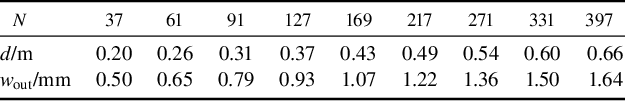
Channel scalability is investigated by simulating MPLC performance with hexagonal laser arrays scaled from 37 to 397 channels. The results obtained under constant system parameters (Table 2) are plotted as the blue curve in Figure 9(a). It is evident that η drops dramatically with increasing channels, implying the necessity to optimize the MPLC setup with respect to the system scale. To realize efficient large-scale CBC under the few-plane limit, d and/or w out, rather than P, are scaled with the input aperture, as specified in Table 4. The corresponding results are exhibited in Figure 9, where the orange or yellow curve represents scaling only w out or d, respectively, while the purple curve represents the case of scaling both parameters. Scaling w out leads to a modest improvement in η, but scaling d is significantly more effective, maintaining η close to 100% as N increases. Furthermore, scaling w out in addition to d is observed to further improve beam quality, enabling an M 2 of 1.57 for the 397-channel array using only five phase masks. However, this improvement in beam quality is achieved at the expense of a reduction in peak intensity due to the larger output beam.
Parameter setup of the CBC system as the channel scales.

(a) η, (b) M 2 and (c) selected M 2 in a small range for CBC of 1027 lasers with P and d taking various values; the left-hand, middle and right-hand columns represent w out/w 0 = 1, 2 and 4, respectively.

4.2 Parameter compromise in the 1027-channel system
To further assess scalability, the combining system is expanded to a 1027-laser array with P and d swept to optimize performance. While other laser array parameters are fixed, w out can be customized, so the optimization (of P and d) is repeated for three cases of w out/w 0 = 1, 2 and 4. The resulting η and M 2 with respect to P and d for each w out condition are shown in Figure 10. It is illustrated that P and d exhibit a distinct reciprocal–complementary relationship. This finding extends the trends observed in the smaller system (Figure 5) to those in the large-N regime, and reveals the fundamental physics of multi-plane diffraction: the plane spacing d governs the characteristic diffraction length, setting the scale for beam expansion and inter-channel interference (diffractive mixing) at each plane. In parallel, the number of planes P determines the available degrees of freedom for sequential wavefront refinement. This interplay creates a design trade-off: a large d promotes strong diffractive mixing per plane, which reduces the number of corrections (P) required, while a compact system (small d) compensates for weaker diffraction at each plane by employing more phase corrections (large P) to achieve the same performance.
Moreover, it is implied in Figure 10(a) that w out has a negligible impact on η, as the three sub-plots show quite similar features. However, Figures 10(b) and 10(c) illustrate that a larger w out is conducive to better beam quality. For the case of w out/w 0 = 1, an M 2 of 1.23 is attained using nine phase masks spaced at 0.9 m. Although larger P and d can further improve beam quality, such a design is undesirable due to the resultant loss of compactness and robustness, leading to a bulky and impractical MPLC device. Within the constraints of P ≤ 9 and d ≤ 0.9 m, the best achievable M 2 values are 1.23, 1.08 and 1.03 for w out/w 0 = 1, 2 and 4, respectively. These results confirm that a larger w out allows for smaller P and d for MPLC to achieve target performance – consistent with the trends observed in Figure 7.
Results of 1027-channel CBC: (a) η (in dB) versus the step of iterations; (b) transverse intensity profile compared with the target mode; (c) changes of beam size in propagation; (d) phase masks and (e) intensity patterns at each plane.

4.3 High-quality CBC of 1027 lasers
Based on the previous findings, the case of w out/w 0 = 2 is selected as a preferable compromise between beam quality and system compactness. This configuration, utilizing seven phase masks spaced at 0.8 m, successfully combines the 1027-channel array into a single output beam with M 2 = 1.16 and η very close to 100%.
Here, η in the unit of decibels (dB) during the MPLC design process is plotted in Figure 11(a), manifesting a rapid convergence within several steps even for a thousand-scale laser array. Excellent alignment with a standard Gaussian beam is observed in Figure 11(b). Moreover, the beam propagation analysis in Figure 11(c) reveals a slightly larger divergence than that of a standard Gaussian beam, which yields an M 2 of 1.16. Finally, the designed phase masks and beam transformation process shown in Figures 11(d) and 11(e) depict that the large-scale laser array is gracefully diffracted, compressed and combined into a single laser beam. It should be noted that strict adherence to the scaling law in Table 4 would require d = 1.06 m and w out/w 0 = 5.3. The present design represents a practical compromise that reduces d and w out at the cost of two additional phase masks. Incidentally, M 2 would be 1.47 with the same MPLC setup if w out/w 0 = 1 were required, consistent with the scaling properties revealed in Figure 11. These results highlight the importance of appropriately increasing d and w out for larger arrays, and affirm the excellent scalability of MPLC-based CBC.
5 Beam steering capability
5.1 Concept and implementation
Electronically steering the output beam by phase control of individual lasers is one of the most attractive advantages of MPLC-based CBC. In this context, beam steering is characterized by a deflection angle θ of the output beam in the near-field. As illustrated in Figure 12, when this tilted beam is focused by a lens of focal length f, it results in a translation Δx = f·tanθ of the focal spot in the far-field plane. This far-field displacement is the measurable quantity that validates electronic beam steering. The underlying principle is that MPLC acts as a linear optical transformer, programmed to convert a set of input fields into a set of orthogonal output modes. Consequently, an MPLC designed to produce multiple output modes is inherently capable of producing any output that lies within the subspace spanned by those modes. From the perspective of linear algebra, any arbitrary optical field, including a deflected Gaussian beam, can be mathematically decomposed into a linear combination of orthogonal modes, which provides the foundation of MPLC beam steering.
Schematic and definition of beam steering.

To equip MPLC with steering capability, it must first be designed to support a set of orthogonal modes. The LG basis is chosen for its circular symmetry that is compatible with hexagonal laser array. In the simulation, the parameter M (introduced in Section 2.3) denotes the maximum number of orthogonal modes the MPLC is designed to handle, which determines the dimensionality of the mode space accessible for beam steering. It is crucial to note that M is a numerical simulation parameter rather than a physical parameter of the laser beams. The design process follows a phase coding method similar to that in Ref. [Reference Wen, Zhang, Sampson, Fontaine, Wang, Fan and Li49]: for each target LG mode, a specific phase pattern is applied to the input array (amplitudes are uniform), making the input field resemble the desired output. The mapping between phase-coded input array and target output modes is illustrated in Figure 13. The colormap therein provides a complete visualization of the complex optical field: the hue represents the phase (e.g., green for 0, purple for ±π), while the brightness represents the amplitude (brighter for higher intensity, dark for 0). Taking the fundamental mode LG00 as an example, since the desired wavefront is a plane wave, a uniform phase pattern is applied to the entire input array.
Phase coding of the laser array according to the output LG mode field.

With mode mapping determined, a multi-mode MPLC can be designed using the wavefront matching method. To implement beam steering, the stochastic parallel gradient descent (SPGD) algorithm is adopted to dynamically optimize laser phases[ Reference Zhou, Feng, Xie, Li, Zhang, Tao, Lin, Wang, Yan and Jing50]. The algorithm’s figure of merit is the on-target intensity at the desired focal spot position corresponding to angle θ. The steering performance is quantified by the steering efficiency, defined as the coupling efficiency between the SPGD-optimized beam and a θ-deflected Gaussian beam. This metric allows us to quantitatively compare the steering capability of MPLCs designed to support different numbers of modes, as analyzed in the following section.
Parameters of the 37-channel MPLC system for CBC beam steering.

5.2 The role of mode multiplexing
The simulation is firstly conducted for a 37-channel array using the parameters listed in Table 5. In this initial analysis, the MPLC parameters (including P = 5 and d = 0.3 m from Table 5) are held constant for all designs, and only the number of supported modes M is varied. For each value of M, a distinct set of phase masks is calculated from scratch using the wavefront matching method (Section 2.3) to perform the specific M-to-M transformation. Thus, while the physical parameters are identical, the actual MPLC design (i.e., the phase plates) is different and uniquely optimized for its target mode set. It should be noted that the efficiency of the ‘no steering’ case is calculated from the overlap between the undeflected (fixed) and θ-deflected (varied with θ) Gaussian beams, providing a baseline for efficiency decay with increasing θ due to the inherent misalignment.
Figure 14(a) presents the steering efficiency versus the normalized deflection angle (θ 0 = λ/πw 0) for MPLCs of different numbers of modes before any device-specific optimization. Two key observations emerge.
-
(1) Multiplexing is necessary: the single-mode MPLC (M = 1) shows no effective steering capability as its efficiency decays as rapidly as the no steering reference, which confirms that a multi-dimensional mode space is essential for encoding beam deflection.
-
(2) A performance trade-off: increasing mode count improves steering at larger angles (slower efficiency decay) but reduces on-axis efficiency (θ = 0). This occurs because the fixed parameters are not optimal for larger M, resulting in imperfect conversion, as seen in the degraded output mode profile for M = 10 in Figure 14(b).
Steering efficiency at different θ for multi-mode MPLCs (a) before and (c) after parameter optimization. Output mode profiles for the 10-mode MPLC (b) before and (d) after optimization.

The relationship between M and steering performance is not trivial. While a larger M provides a higher-dimensional space for beam deflection, it also imposes a more complex wavefront transformation, which is difficult to achieve perfectly with a constrained device (fixed P, d), leading to the observed trade-off in Figure 14(a). The degradation in on-axis efficiency and output mode profile indicates that the fixed parameters from Table 5 are suboptimal for larger M. To isolate the impact of M and evaluate its true potential, the key parameters (P, d) are re-optimized for each multi-mode MPLC (M = 3, 6, 10) under the practical constraints of P < 10 and d < 1 m. The optimization successfully restored the on-axis efficiency to more than 95% and improved the output mode quality as depicted in Figure 14(d) for M = 10.
The efficiency versus deflection angle after optimization is depicted in Figure 14(c), implying that more modes do not invariably yield better steering capability. The 3-mode MPLC performs better than 6- and 10-mode MPLCs with η > 80% at θ 0. This indicates that the relationship between the number of multiplexed modes and steering capability is non-trivial, and simply expanding the mode space does not guarantee performance. On the other hand, the potential of beam steering is possibly limited by phase-only control, and amplitude modulation should be taken into account to improve the control technique, which warrants further investigation.
Demonstration of beam steering by the 10-mode MPLC: (a) transverse intensity profiles in the far-field for different commanded θ; (b) corresponding two-dimensional far-field patterns; (c) beam evolution in MPLC for deflection angles of θ 0 and 0.

5.3 Direct demonstration of beam steering
To unambiguously demonstrate the beam steering capability within a fixed device, the following results are obtained using the same 10-mode MPLC (with P = 5, d = 0.3 m, prior to optimization, as discussed in Section 5.2). For this fixed device, steering to different angles is achieved solely by applying different phase patterns to the input laser array using the SPGD algorithm, without altering the MPLC itself. Therefore, the steering performance across different angles is directly comparable, as it probes the capabilities of a single, static device. The transverse intensity profiles for five commanded deflection angles (0, 0.5θ 0, θ 0, 1.5θ 0, 2θ 0) are illustrated in Figure 15(a). Although a discrepancy exists between the commanded and achieved deflection angles, a clear lateral shift of the intensity peak is observed, which provides quantitative evidence of successful beam deflection. Furthermore, Figure 15(b) offers more direct visual proof by supplying the corresponding far-field spots at the five angles, showing that the main lobe systematically moves across the field of view with increasing θ. Finally, the evolution of beam profile in the 10-mode MPLC for the deflected (θ = θ 0) and undeflected (θ = 0) cases is illustrated in Figure 15(c). Each sub-figure represents the electric field after phase modulation at a different plane, showing that a tilt wavefront is gradually formed during MPLC propagation for beam steering.
The results confirm successful beam steering, although the steered laser spot deteriorates as θ increases, and slight sidelobes become visible at 2θ 0, as shown in Figure 15(b). Quantitatively, the power fraction contained in the main-lobe is calculated to be 88.2%, 88.1%, 87.1%, 83.1% and 69.6% at θ = 0, 0.5θ 0, θ 0, 1.5θ 0 and 2θ 0, respectively. The relatively low main-lobe ratio at θ = 0 is attributed to the non-optimized MPLC parameters, indicating some power scattering into the background, which is consistent with Figures 14(a) and 14(b). For comparison, the PIB ratio for a classical tiled-aperture CBC system with the same 37-channel array is only 38.0% at θ = 0, which can be increased to less than 61% by further compacting the beam spacing[ Reference Jabczynski and Gontar40]. Therefore, the MPLC approach (under non-ideal parameters) achieves a higher main-lobe power across different steering angles than the tiled-aperture system does in its ‘no steering’ case (under optimal parameters).
6 Conclusion
The MPLC technique is modeled and numerically investigated for CBC applications. Through optical parameter sweeps in MPLC-CBC system, it is revealed that the number of planes (P) and plane spacing (d) are the main influential parameters, while the grid size (δ) only needs to ensure the spatial resolution of a single laser beam (δ ≤ 83 μm for a Gaussian beam with a 0.5 mm radius). As for the laser array, better compactness relieves the strict requirement on MPLC, so it is beneficial to tile the beams in a dense array with small spacing. The influence of output beam size is similar, showing that a smaller compression ratio between the input and output aperture sizes leads to better results.
Furthermore, the channel scalability analysis indicates that the plane spacing should be increased with the total aperture of the laser array, and it is possible to improve beam quality by properly increasing the size of the combined beam. CBC performance can be maintained using only five planes for 397 lasers, and the channel count is further increased to 1027 using seven phase masks spaced at 0.8 m, delivering a combined beam with efficiency close to 100% and M 2 of 1.16. In addition, it is found that mode multiplexing is critical for beam steering, and both the number of modes and mode qualities affect steering performance, requiring the development of high-dimensional mode-multiplexing MPLC and suitable control techniques. The results demonstrate that MPLC-based CBC achieves high combining efficiency and scales effectively to over 1000 beams, highlighting its potential for large-scale applications.


 Open access