





1. Introduction
When pumping a fluid through a narrow tube into a large reservoir, one will generally observe a jet emerging from the end of the tube. Unlike a flow emanating from a point-mass source, such a jet is discharged in a manner that the fluid momentum is concentrated at the tip of the tube. When this momentum is released from the tip into the vast bulk region, it will entrain and eject fluid around the edge, emitting a jet out of the tip. This is the well-known Landau–Squire (LS) jet driven by a point source of (constant) momentum. It has been shown that this particular jet flow admits an exact (self-similar) solution of the Navier–Stokes equation (Squire Reference Squire1951; Landau & Lifshitz Reference Landau and Lifshitz1959). The solution is constructed by assuming that the flow is symmetric about the polar angle in the direction of the jet. Expressed in axisymmetric spherical polar coordinates (r,θ) with the tip as the origin, the fluid velocity (ur, uθ) in the weak jet limit due to a small point force F takes the following form (Landau & Lifshitz Reference Landau and Lifshitz1959):
 \begin{equation}({u_r},{u_\theta }) = \frac{F}{{4{\rm \pi} \eta r}}\left( {\cos \theta , - \frac{1}{2}\sin \theta } \right),\end{equation}
where η denotes the dynamic viscosity of the fluid. The velocity (1.1) is shown to decay as 1/r away from the tip. From a dimensional point of view, this is the only plausible solution because the force F under the creeping flow condition is expressed as the product of viscosity, velocity and length scale.
Experimentally, LS flows are commonly realized by pressure discharge using nanopipettes or conical nanopores that are able to render pressure buildup at their tips, as seen for example in nanovelocimetry or nanofluidic ionic diodes (Laohakunakorn et al. Reference Laohakunakorn, Gollnick, Moreno-Herrero, Aarts, Dullens, Ghosal and Keyser2013; Lan et al. Reference Lan, Edwards, Luo, Perera, Wu, Martin and White2016; Secchi et al. Reference Secchi, Marbach, Niguès, Stein, Siria and Bocquet2016; Wu, Rajasekaran & Martin Reference Wu, Rajasekaran and Martin2016). In contrast to such familiar pump discharge LS flows at nanoscales, in this work we demonstrate both experimentally and theoretically that a new class of LS-type flow can be generated in a purely electrohydrodynamic (EHD) manner. This can be done by applying an ambient uniform AC electric field over a sharp conducting needle at microscales. The effect is capable of producing not only a jet-like streaming from the tip but also a reverse flow pattern, which is very distinct from the classical LS flow. Prior to presenting our results, we explain below our incentives for studying such EHD LS-type flows.
The typical 1/r velocity field divergence of the LS flow at the discharge tip is a result of the point momentum exerted at the conical tip. This 1/r velocity dependence is exactly the signature of the fundamental Stokeslet point-force solution of the Stokes equation under the creeping flow condition (Kim & Karrila Reference Kim and Karrila1991). However, such a singular behaviour is not limited only to hydrodynamic flows. It can also occur in electric fields by virtue of the analogy between hydrodynamics and electrostatics. A well-known example is the strong local electric field induced by the presence of a conducting conical tip (Jackson Reference Jackson1998), as occurs in a Taylor cone during electrospray ionization (Gañán-Calvo et al. Reference Gañán-Calvo, López-Herrera, Herrada, Ramos and Montanero2018) or in an ultra-sharp scanning probe in scanning tunnelling microscopy (STM) (Binnig & Rohrer Reference Binnig and Rohrer1987).
The present work is motivated by a possible issue arising from the use of a sharp metal tip for performing electrochemical STM (ECSTM) probing in an aqueous solution (Itaya & Tomita Reference Itaya and Tomita1988). In such probing, the excess charges induced by the applied electric field might generate nonlinear electrokinetic flows. Since such flows could be further amplified near the tip, these effects can strongly influence the sample transport and detection in the solution.
How the strength of the local electric field E varies with the distance r from the tip can be described as follows according to Jackson (Reference Jackson1998):
 \begin{equation}E\sim (V/{r_0}){(r/{r_0})^{ - n}}.\end{equation}
Here V denotes the applied voltage, r 0 is the local length scale around the tip (e.g. the curvature of the tip), and n ( > 0) is an exponent depending on the opening angle 2θ 0 of the cone. For a sharp (slender) cone with  ${\theta _0} \ll 1$, the exponent in (1.2) behaves as (Jackson Reference Jackson1998)
 \begin{equation}n \approx 1 - {[2\ln (2/{\theta _0})]^{ - 1}},\end{equation}
which approaches 1 as  ${\theta _0} \to 0$. It means that E will change nearly as 1/r as the sharp tip is approached, unlike the plasmonic 1/r 3/2 decay when the sharp tip is subjected to a transverse electromagnetic field (Miloh Reference Miloh2016). The question one may ask then is: can such a diverging electric field be effectively used to generate a LS-like flow?
We first inspect how the electric force near the tip behaves due to the local electric field E that changes nearly as 1/r. Since the electric (Columbic) force density  ${\boldsymbol{f}_e} = {\rho _e}\boldsymbol{E}$ has to acquire a non-zero charge density ρe resulting from charging by E, fe generally varies nonlinearly with E, decaying at a rate of at least 1/r 2. If fe decays as 1/r 3, the total electric force ${\boldsymbol{F}_e} = \int {{\boldsymbol{f}_e}\,\textrm{d}\mathcal{V}}$, defined over a volume ${\mathcal{V}}$ enclosing the tip, varies slowly with the size of ${\mathcal{V}}$ and hence is roughly a constant. In the case where fe happens to decay faster than 1/r 3 or to act within a region of a finite extent near the tip, Fe will become a constant around the tip. In either case, Fe is concentrated at the tip (located at xtip), rendering a fluid motion governed by the following point-force-driven Stokes equation:
 \begin{equation}- \boldsymbol{\nabla }p + \eta {\nabla ^2}\boldsymbol{v} ={-} {\boldsymbol{F}_e}\delta (\boldsymbol{x} - {\boldsymbol{x}_{tip}}),\end{equation}
where v is the fluid velocity field and p is the pressure. The flow field v around the tip can then be described by the well-known Stokeslet solution (Kim & Karrila Reference Kim and Karrila1991):
 \begin{equation}\boldsymbol{v} = \frac{{{\boldsymbol{F}_e}}}{{8 {\rm \pi}\eta }}\boldsymbol{\cdot }\left[ {\frac{\boldsymbol{I}}{r} + \frac{{(\boldsymbol{x} - {\boldsymbol{x}_{tip}})(\boldsymbol{x} - {\boldsymbol{x}_{tip}})}}{{{r^3}}}} \right],\end{equation}
making the fluid speed  $u = |\boldsymbol{v}|\ \propto 1/r$. In other words, to realize a point-force-like flow $u\ \propto 1/r$, fe has to decay as 1/r 3 or faster.
Such EHD LS flows in character will be very distinct from the usual pump discharge LS flows. First, they differ by how their velocities behave in terms of the driving force. Under the creeping flow assumption, because of the nonlinear dependence of fe on E, an EHD LS flow field will be generally nonlinear in E, in contrast to the usual LS velocity field which is linear in the driving pressure head (Landau & Lifschitz Reference Landau and Lifshitz1959). Second, these effects can be manifested by imposing high-frequency AC electric fields under which charge polarization can occur to render a field-dependent charge density ρe and hence a nonlinear fe needed for producing these EHD flows. In addition, by utilizing such nonlinear electric forcing, one is able to generate a variety of EHD flows such as AC electro-osmosis (Ramos et al. Reference Ramos, Morgan, Green and Castellanos1999; González et al. Reference González, Ramos, Green, Castellanos and Morgan2000), AC Faradaic streaming (Olesen, Bruus & Ajdari Reference Olesen, Bruus and Ajdari2006; García-Sánchez, Ramos & González Reference García-Sánchez, Ramos and González2011) and AC electrothermal flows (Ramos et al. Reference Ramos, Morgan, Green and Castellanos1998; Green et al. Reference Green, Ramos, González, Castellanos and Morgan2001; Gagnon & Chang Reference Gagnon and Chang2009). Moreover, the characteristics of such EHD flows can be effectively tuned and controlled by adjusting AC frequencies, making EHD forcing more desirable compared with pressure forcing for more precise manipulations of fluid flows.
The present work is organized as follows. We begin with the experimental section in § 2 by detailing how we prepare the sharp nanotip and conduct the experiments. In § 3, we provide an overview for the variety of EHD LS flow patterns observed in this work. In §§ 4–6, we present the detailed features for three distinct EHD LS flows: AC electrothermal jet, AC electro-osmotic impinging flow and AC Faradaic streaming. New physical mechanisms and models are also proposed in line to account for these flows. Finally, § 7 summarizes our new findings in comparison with existing studies. Possible impacts on technological applications are also put forward.
2. Experimental section
In this work, we used tungsten wires (of 250 μm in diameter) to construct an electrode system for generating EHD LS flows. The electrode pair consisted of a conical needle and a cylindrical wire in an orthogonal arrangement of 180 μm in separation (see figure 1a). The conical needle was made by using the drop-off electrochemical etching technique (Ibe et al. Reference Ibe, Bey, Brandow, Brizzolara, Burnham, DiLella, Lee, Marrian and Colton1990) with a strong electrolyte solution (1.5 M KOH). Specifically, having dropped off a tungsten wire vertically through the centre of a film of the solution held by a metal cathodic ring (subjected to 3 Vrms under 50 Hz), an ultrasharp needle having an opening angle  $2{\theta _0}\sim 10^\circ$ (measured from the apparent opening angle of the microscopic spine shown in figure 1b) and a small tip of ~25 nm in radius of curvature was readily produced (see figure 1c). The needle and another untreated wire were then inserted in precut cracks in a reservoir (of ~4 mm in both diameter and depth) made of a PDMS block. How to position the needle and the wire are described in more detail below.
(a) The electrode pair made of a sharp tungsten needle in an orthogonal arrangement with another tungsten wire. (b) The zoomed-in image of the highlighted area in (a), revealing the microscopic spine at the front end of the needle. (c) A close-up view of the tip of a sharp tungsten needle, taken by SEM at × 105 magnification. (d) The needle-wire electrode system embedded in a PDMS block on a glass slide.

We first inserted the wire into a vertical crack across the reservoir's diameter. Then we placed the needle over the wire in an orthogonal manner and had the former embedded into a horizontal crack along the central line of the reservoir on a glass slide. This step was a prepositioning between the needle and the wire. The entire body of the needle had to be sufficiently long so that the other end of the needle was left outside the PDMS block. This allowed us to adjust the needle's position by gently pulling the other end outward. After reaching the desired distance to the wire, we pressed the needle down by clamping the two ends of the needle using separate forceps at the same time. One end remained on the exterior side outside the PDMS block and the other lay on the interior side close to the reservoir wall away from the tip. When both the needle and the vertical wire's outline could be seen clearly on the same focal plane under a microscope, it could be assured that the needle was centred on the midplane through the wire's diameter.
Both the needle and the vertical wire were placed at a distance from the bottom surface which was approximately 1/3 the reservoir depth (~4 mm). Further with proper sealing and wiring, the whole device was ready for the experiment (see figure 1d). Prior to the experiment, we treated the entire device with O2 plasma for approximately 10 min, and then injected the desired solution and tracer particles. We employed green fluorescent polystyrene beads (of 0.92 μm in diameter, Thermo Fisher Scientific) to trace flow streamlines and measure fluid speeds. Note that at the high AC frequencies of 102 Hz–MHz used here, the flows were not time oscillatory in synchronization with the applied AC field. The reason is that the fluid motion was not driven by linear electric forces due to fixed charge but by nonlinear electric forces due to induced charge polarization. Therefore, what we observed here were actually time-averaged flow phenomena driven by time-averaged electric forces.
To make EHD LS flows more apparent, we mainly used relatively low conductivity solutions such as deionized water and low concentration NaCl solutions (of conductivity  ${\sigma _0} = 1.5 - 150\;{\rm \mu} \textrm{S}\;\textrm{c}{\textrm{m}^{ - 1}}$), so that the electric fields were less screened by counterions because of the relatively thick double layer (of the Debye screening length λ 0 = 7–70 nm according to ${\lambda_0} \approx {(\textrm{D}{\varepsilon _0}/{\sigma _0})^{1/2}}$, where ε 0 is the solution permittivity and D is the ion diffusion coefficient of ~10−5 cm2 s−1). After making the electrode system connected to a function generator (at 5–20 V pp and 100–10 MHz, Agilent 33220A), we observed fluid flows using an inverted microscope (Nikon TE2000S) with a fluorescent lamp (Nikon C-SHG1). The images were captured using a CCD camera (of 30 frames s−1 under the exposure time 5–200 ms, CoolSNAP HQ2, Photometrics) though a × 20 or × 100 objective and a fluorescence filter (450–490 nm excitation/505 nm dichroic/520 nm emission). Fluid streamlines were obtained by tracking the movements of the tracer particles using an image analysis software (Image-Pro Plus). Since our main interest here is to look at a LS-like flow near the tip, we focussed on the region (−90° < θ < 90°) ahead of the tip and measured how the fluid speed U (i.e. the magnitude of the fluid velocity) varied with distance r to the tip. This was to prevent a possible intervention by the electrokinetic slip flow generated from the needle surface behind the tip. Such a procedure also helped to reduce the unwanted dielectrophoretic (DEP) effect on the tracer particles for preventing their trajectories from being deviated from streamlines. We have identified experimentally that the tracer particles merely migrated at an order of 10 μm s−1 due to DEP, as seen at 10 MHz. Such DEP velocity was also consistent with the estimated DEP velocity scale for micron-sized particles according to ${U_{DEP}}\sim ({a^2}/3\eta ){\varepsilon _0}\boldsymbol{\nabla }|\boldsymbol{E}{|^2}$ (Morgan & Green Reference Morgan and Green2003) with |E| ~ V/L by applying voltage V ~ 10 V over the typical electrode separation L ~ 10 2 μm in an aqueous solution. This velocity was much slower than the typical fluid speed by an order of 102 μm s−1 observed in most of the situations. Electrophoresis due to native surface charge will not take place at all. This is because the system was operated under high frequency AC fields, so the time-averaged electrophoretic velocity was identically zero.
3. Distinct AC Landau–Squire flows
Figure 2 shows some representative images for the observed flow phenomena (figure 1a–e) together with the flow map (figure 2f). There are mainly three types of EHD LS flows: AC electrothermal flow (ACET) (figure 2a), AC electro-osmotic flow (ACEO) (figure 2b) and AC Faradaic streaming (ACFS) (figure 2c), depending on the applied AC voltage and frequency. All these flows display the signature of the classical LS flow pattern: i.e. an abrupt entrainment toward the tip followed by immediate ejection from the tip as tracer particles are moving in and out of the region near the tip.
Three typical types of AC Landau–Squire flows observed in the experiments: (a) AC electrothermal (ACET) jetting, (b) AC electro-osmotic (ACEO) impinging flow and (c) AC Faradaic streaming (ACFS). Mixed flows can also occur: panel (d) shows a suppression of (a) by (b), and panel (e) displays a concurrence of (b) and (c). Arrows indicate flow directions. These different flow patterns depend on the ranges of the applied voltage V (in peak-to-peak voltage V pp) and frequency (ω), as shown in the flow map in panel (f). These images and data are collected using deionized water.

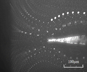
In terms of the appearance of these flows, they can take different forms and sometimes co-exist. For a given AC voltage, ACET and ACFS display the typical LS-like jetting from the tip, dominating respectively at high frequencies ( > 1 MHz) and at low frequencies (< 1 kHz). ACEO, on the contrary, appears as a reverse form impinging over the tip, occurring in the intermediate frequency regime (1–100 kHz). However, if the frequency is selected in the range near the borders between these flows, different flow types can emerge jointly. Such mixed flows can happen in two ways. The first occurs at a frequency slightly lower than that of ACET, showing a suppression of the ACET jet by a much stronger ACEO impinging flow (figure 2d). The second happens at a frequency slightly higher than that of ACFS. This results in a violent ACFS jet opposed by an ACEO impinging flow, giving rise to a swirling flow around the tip (figure 2e). Note that because of the axisymmetric needle geometry, such a swirling should appear as a single toroidal vortex.
While qualitatively these three EHD LS flow types appear in different forms, it is necessary to identify quantitatively whether they all exhibit the point-force-like flow characteristic  $u\ \propto 1/r$ described by (1.1). In the experiments, we used tracer particles to determine their trajectories along LS-like streamlines (figure 2a–c) near the tip and measured the displacements between consecutive movements in the region (−90° < θ < 90°) ahead of the tip. The speed at a given value of r can readily be determined in a forward difference manner with the measured displacement divided by the time interval.
The results are presented in figure 3 by plotting the measured speed U against distance to the tip, r. Each set of data points for given applied voltage and frequency were taken from all measurable LS-like paths in the movie recorded under that condition. As shown in figure 3, the measured speeds for all the three flow types exhibited the point-force-like characteristic  $U\ \propto 1/r$. For the ACET jet (figure 3a), the 1/r decay only appeared in the region near the tip. On the other hand, in the region far away from the tip, the velocity decay became slower than 1/r, which may be a consequence of the global ACET set up by temperature gradients in the bulk fluid. For the ACEO impinging flow (figure 3b) and the ACFS jet (figure 3c), the 1/r decay prevailed, except in the region close to the tip where these trends were reversed. The slowdown in the ACEO impinging flow near the tip was attributed to the co-existing micro ACET ejection from the tip. The adverse effect on the ACFS jet was caused by positive DEP on the tracer particles. This DEP effect acted to oppose the jet and became stronger approaching toward the tip. The accumulation of the tracer particles near the tip was the evidence of such a DEP effect (see figure 2c). Despite the above, the observed 1/r decay indicated the existence of localized electric forces around the tip. The appearance of this point-force flow characteristic in all these three flow types also implied that it must be part of the universal singular features existing near the tip due to the conical needle geometry albeit with different mechanisms governing these dissimilar flow types.
Plots of measured flow speed (U) against distance from the tip (r) in deionized water: (a) AC electrothermal jet (at 1 MHz), (b) AC electro-osmotic impinging flow (at 1 kHz) and (c) AC Faradaic streaming (at 100 Hz). These plots basically display the point-force-like flow characteristic  $U \propto 1/r$. Exceptions occur in regions either far away from the tip (in (a)) or near the tip (in (b) and (c)) due to other co-existing AC effects.

It is also worth mentioning that the dependence of the actual fluid velocity U on the polar angle θ may not agree with the common LS solution given by (1.1). The reason is that while each flow type is pre-dominated by the flow generated by the more intensified local electric force around the tip, it is often accompanied by an electrokinetic slip flow set up by an electric force acting over the thin electric double layer around the needle surface away from tip. The latter may significantly change how the fluid velocity varies with θ. Nevertheless, this will not change the prevailing point-force flow characteristic  $u\ \propto 1/r$.
We should remark that these EHD LS flows were actually time-averaged nonlinear electrokinetic phenomena arising from rapid charging and discharging by high-frequency AC fields. Specifically, every one of them was driven by a non-zero time-averaged electric force  $\langle \,{\boldsymbol{f}_e}\rangle = \langle {\rho _e}\boldsymbol{E}\rangle$, where the charge density ρe was field-dependent due to charging/discharging by the applied electric field E. Similar nonlinear effects might arise under DC fields. But they will not display any frequency dependence like those in DC fields under which the amount of induced charges (i.e. ρe) can be further modulated by the applied AC frequency. To see how each of these EHD LS flows arises under AC fields, in the subsequent sections we will provide a more in-depth account for the physics behind each flow type.
4. AC electrothermal jet
4.1. Atypical ACET flow
We begin by inspecting the observed ACET jet in more detail. This flow typically occurs at frequencies around the characteristic RC frequency near the tip  ${\omega _{tip}} = {(2{\rm \pi})^{ - 1}}({\sigma _0}/{\varepsilon _0})({\lambda_0}/{b_0})$ (ranging from 100 kHz to 1 MHz) or higher, where σ0 is the solution conductivity, ε 0 the permittivity, λ 0 the corresponding electric double layer (Debye) thickness and b 0 is the tip radius of curvature. The flow of this sort is identified to be mainly driven by solution conductivity gradients caused by intense Joule heating around the tip, in contrast to the ACET flow around a conical tip due to permittivity gradients which generally occur at much higher frequencies (Miloh Reference Miloh2016).
To identify the dependence of the ACET jet on the applied voltage V, we collect the measured speed data at different positions at each value of V shown in figure 3(a) and convert them into the corresponding values of the force strength exerted on the jet,  $F=4{\rm \pi} \eta \textit{Ur}$. Figure 4(a) plots F against V. It reveals that the data in the high V ( > 10 V pp) regime seem to be more in favour of $F\ \propto {V^3}$ than the V 4 dependence as predicted by the standard ACET theory (Ramos et al. Reference Ramos, Morgan, Green and Castellanos1998; Green et al. Reference Green, Ramos, González, Castellanos and Morgan2001). A departure from the V 4 law has been observed for high-conductivity solutions ( > 104 μS cm−1) in planar microelectrode systems (Sin et al. Reference Sin, Gau, Liao and Wong2010). Here we find that a discrepancy between the experimental data and the V 4 law can also occur in low-conductivity solutions ( < 103 μS cm−1) using a conical needle. This discrepancy becomes even more evident in the low V ( < 10 V pp) regime in which F seems to be independent of V. Note that the measured fluid speed U in this regime still behaves much like 1/r except for the region far from the tip (see figure 3a). The unmatched data trend with the V 3 law seen in the low-V regime is attributed to the fact that the selected AC frequency here is close to the value of a transition to an ACEO impinging flow, which partially suppresses the ACET ejection from the tip. Furthermore, the force in an aqueous solution of conductivity 100 times that of deionized water does not appear much greater than that in the latter case, as can be seen in figure 4(b) in which the measured forces are normalized with respect to the corresponding frequencies as F × ω. This finding does not comply with the standard ACET theory (Ramos et al. Reference Ramos, Morgan, Green and Castellanos1998) either since this theory predicts that the fluid speed is always increased as solution conductivity is increased. In fact, from a dimensional point of view, since this theory also predicts the V 4 law, the fact that the measured force does not increase with solution conductivity cannot be compatible with the V 4 dependence. This is another reason why we believe that the V 3 law is more favoured than the V 4 law in figure 4. Below we offer an alternative explanation to rationalize these atypical results observed in the experiment.
(a) Replot of the data in figure 3(a) in terms of the force  $F=4{\rm \pi} \eta \textit{Ur}$ against the applied voltage V for AC electrothermal jet in deionized water (at 1 MHz) and 1 mM NaCl solution (at 6 MHz). The data in the high-V regime appear to be more in favour of $F \propto {V^3}$ than $F \propto {V^4}$, as predicted by the standard ACET theory. (b) Replot of the data in (a) with F × ω against V, showing a rough collapse of the data in the high-V regime. This indicates that F varies inversely with the applied field frequency ω regardless of solution conductivity. Multiple data points at a given value of V are the data points taken from different values of r shown in figure 3(a).

Similar to the situation of a conducting liquid cone dispersed by electrospray (Crowley Reference Crowley1977), the heat transfer around the needle tip in a low-conductivity solution is mainly through internal Joule heating effects by the needle and its dissipation to the bulk fluid by means of convection/conduction processes, as illustrated in figure 5(a). A simple energy balance over the conical needle allows us to determine the temperature rise (Tw − T∞) within the needle with respect to the bulk temperature T∞:
 \begin{equation}h({T_w} - {T_\infty })2{\rm \pi} b = {\dot{S}_{ohm}}A.\end{equation}
Here  ${\dot{S}_{ohm}} = {I^2}/{\sigma _{needle}}{A^2}$ represents the Ohmic heat generation rate (per unit volume), taking place within the needle of conductivity σneedle and carrying an electric current I through the local cross-sectional area A = ${\rm \pi}$b 2 of radius b = z tanθ 0 at a distance z from the tip. Since b is assumed to be small, the heat transfer on the fluid side is mainly dominated by conduction, thus yielding h ≈ k/b with k being the thermal conductivity of the fluid. Therefore, the temperature rise ΔT ≡ Tw − T∞ can be taken as
 \begin{equation}\Delta T = \frac{{{I^2}}}{{2{{\rm \pi} ^2}k{\sigma _{needle}}{b^2}}}.\end{equation}
Since b = z tanθ 0,  $\Delta T\ \propto {z^{ - 2}}$ will grow very rapidly as the tip is approached, turning the tip into a local hotspot. Because the needle is generally covered by a thin oxide layer having conductivity ${\sigma _{needle}} \approx 6\;\textrm{S}\;{\textrm{m}^{ - 1}}$, the temperature rise around the tip of b 0 ≈ 25 nm in an aqueous solution with thermal conductivity like that of water (k ≈ 0.6 W m−1 K−1) can be as high as ΔT ~ 20 °C when subjected to a typical electric current I ~ μA carried by the needle. Note also that such a local Joule heating by the needle can be manifested only in the region near the tip, where σneedle is significantly reduced due to the thin oxide layer that is formed during the electrochemical etching process. As we move away from the tip, the influence of this thin oxide layer is gradually diminished, making σneedle approach the value of pure tungsten ~107 S m−1 and hence rendering ΔT ≈ 0.
Internal Joule heating and double layer charging mechanisms responsible for the observed ACET jet. (a) The heating is generated from the Joule current passing through the needle, making the needle hotter than the fluid. (b) This internal Joule heating gets more intensified approaching toward the tip, which turns the tip into a local hotspot. As a result, the charging tangential current into the hotspot becomes hotter than the discharging current out of the hotspot, which causes a coion buildup within the hotspot. (c) The resulting electric force is concentrated at the tip and pointing outward, thereby drawing fluid from the bulk toward the tip so as to produce an ACET jet emanating from the tip.

Next, we consider the charge balance around the conical tip. Because of the slender needle geometry in the region close to the tip, the current on the needle surface acts virtually in a direction parallel to the cone. Since the tip now serves as a hotspot, it will receive a hotter tangential current density  ${j_{/{/}}}(T) = ({\sigma _0} + \Delta \sigma (T)){E_{/{/}}}$ with a conductivity increment $\Delta \sigma (T) = {\sigma _0}\beta \Delta T$ where $\beta = (1/{\sigma _0})(\partial \sigma /\partial T)$ (Ramos et al. Reference Ramos, Morgan, Green and Castellanos1998). On the other hand, the normal current density ${j_ \bot } = {\sigma _0}{E_ \bot }$ leaving out of this hotspot region is generally colder. As a result of these hot current charging and cold current discharging, there is a substantial buildup of coions within the hotspot (figure 5b). The surface heating by the needle also turns this local hotspot into a heated capacitor whose value $C(T) \approx {\varepsilon _0}/\lambda_0 (T) \approx ({\varepsilon _0}/{\lambda_0}){(1 + \beta \Delta T)^{1/2}}$ is increased due to a decrease in the Debye length $\lambda_0 (T) \approx {(\textrm{D}{\varepsilon _0}/\sigma (T))^{1/2}} = {\lambda_0}{(1 + \beta \Delta T)^{ - 1/2}}$. Extending the study of Gagnon & Chang (Reference Gagnon and Chang2009), we adopt a heated resistive capacitive model: $C(T)\partial \Delta \phi /\partial t = {j_{/{/}}}(T) - {j_{\bot}}$, having an electric potential change Δϕ across the double layer. Using this model, the local hotspot will undergo charging according to
 \begin{equation}({\varepsilon _0}/{\lambda_0}){(1 + \beta \Delta T)^{1/2}}\partial \Delta \phi /\partial t\sim {\sigma _0}\beta \Delta TE.\end{equation}
Further making use of  $\Delta T \propto {I^2} \propto {V^2}$ from (4.2), we find $\Delta \phi \propto {\omega ^{ - 1}}{\sigma _0}{\lambda_0}{V^2}$ at sufficiently high values of V. Having the charge density ${\rho _e}\sim {\varepsilon _0}\Delta \phi /\lambda_0^2$ within the double layer of the extent ${\lambda_0}({\propto} \sigma _0^{ - 1/2})$, the electric force ${F_e}\sim {\rho _e}\lambda_0^3E\sim {\varepsilon _0}\Delta \phi {\lambda_0}E$ is found to behave as
 \begin{equation}{F_e} \propto {\omega ^{ - 1}}\sigma _0^0{V^3}.\end{equation}
This localized force acts in a direction pointing outward from the tip (see figure 5c) and thus in turn drives the fluid to form an ACET jet emanating from the tip. Equation (4.4) explains not only the measured force's behaviour  $F \propto {V^3}$, seen in figure 4, but also the independence of F on σ 0. The latter is supported by the collapse of the data of different solution conductivities shown in figure 4(b). It is plausible that the data behaviour is more in favour of $F \propto {V^3}$ according to (4.4) than $F \propto {V^4}$ from the theory of Ramos et al. (Reference Ramos, Morgan, Green and Castellanos1998), since the latter always predicts an increase of F with σ 0 and thus basically cannot explain the data shown in figure 4(b). In the next subsection, we will show the predictions of this classical theory specifically applied to our conical needle system and provide further clarifications for why such a theory cannot fully explain our experimental findings.
4.2. Classical ACET theory revisited
To better elucidate why the observed ACET jet does not behave according to the classical ACET theory given by Ramos et al. (Reference Ramos, Morgan, Green and Castellanos1998), it is necessary to revisit this commonly used theory to see what it predicts for our conical needle electrode system.
In contrast to our heated double layer charging theory described in § 4.1, Ramos et al.'s theory describes the ACET flow set up by an induced space charge in the bulk fluid due to Joule heating. According to their theory, the effects at work generally involve a coupling between electric field E, temperature field T and flow field v in the surrounding fluid, governed by Gauss's law (4.5a), dynamic charge balance (4.5b), heat balance (4.5c) and equations of fluid motion (4.5d–f):
 \begin{gather}\boldsymbol{\nabla }\boldsymbol{\cdot }(\varepsilon \boldsymbol{E}) = {\rho _e},\end{gather}
 \begin{gather}\partial {\rho _e}/\partial t + \boldsymbol{\nabla }\boldsymbol{\cdot }(\sigma \boldsymbol{E}) = 0,\end{gather}
 \begin{gather}\boldsymbol{\nabla }\boldsymbol{\cdot }(\rho \boldsymbol{v}T) = k{\nabla ^2}T + \sigma |\boldsymbol{E}{|^2},\end{gather}
 \begin{gather}\boldsymbol{\nabla }\boldsymbol{\cdot }(\rho \boldsymbol{v}) = 0,\end{gather}
 \begin{gather}\langle {\boldsymbol{f}_e}\rangle - \boldsymbol{\nabla }p + \eta {\nabla ^2}\boldsymbol{v} = 0,\end{gather}
 \begin{gather}{\boldsymbol{f}_e} = {\rho _e}\boldsymbol{E} - (1/2)|\boldsymbol{E}{|^2}\boldsymbol{\nabla }\varepsilon .\end{gather}
Here  $\varepsilon = {\varepsilon _0}(1 + \alpha \Delta T)$ is the fluid's permittivity that decreases linearly with temperature rise ΔT owing to the negative thermal coefficient $\alpha = (1/{\varepsilon _0})(\partial \varepsilon /\partial T) \approx{-} 0.004\;{\textrm{K}^{ - 1}}$ (Lide Reference Lide1994), whereas the fluid's conductivity σ = σ 0(1 + βΔT) increases with ΔT because of the positive thermal coefficient $\beta = (1/{\sigma _0})(\partial \sigma /\partial T) \approx 0.02\;{\textrm{K}^{ - 1}}$ (Lide Reference Lide1994). The temperature rise ΔT = T − T 0 is defined with respect to the unheated state ‘0’. The changes in ε and σ due to ΔT will affect the charge density ρe through (4.5a) and (4.5b). The temperature T is determined from (4.5c) with k being the thermal conductivity and ρ the density of the fluid.
We restate that the key difference between Ramos et al.'s theory and ours is the underlying concept. In their theory, the charging can occur both dielectrically and conductively due to (4.5a) and (4.5b) everywhere in the bulk fluid. The force (4.5f) thus also acts everywhere on the bulk fluid. In contrast, in our theory the charging merely happens within the thin double layer around the needle, and hence the resulting force (4.5f). To be more specific, the electric field in (4.5a) is actually the electric potential gradient across the double layer in the Poisson–Boltzmann equilibrium, turning the double layer into a dielectric capacitor whose charge density is determined by (4.5b) in a conductive manner through the current injection/ejection σE from/to the bulk at the outer edge of the double layer. Because of this conceptual difference, the outcomes predicted by these two theories will exhibit completely different dependences on the variables involved. In this subsection, we will employ Ramos et al.'s theory to describe the ACET around a conical needle. The focus here will be the use of this theory to demonstrate how the electric force density fe in (4.5f) varies with ΔT and E so as to reveal how the fluid responds to the time-averaged force density 〈fe〉 according to (4.5d) and (4.5e).
According to Ramos et al. (Reference Ramos, Morgan, Green and Castellanos1998), because ΔT is typically small and so are the permittivity and conductivity variations Δε and Δσ, the following assumptions can be made to simplify (4.5a–f): (i) variations of other fluid properties ρ, η and k due to ΔT are negligible; (ii) the electric field due to induced charges is much weaker than the applied electric field; (iii) the transport of mobile ions are influenced by their electromigration fluxes much stronger than diffusive and convective fluxes; and (iv) convective heat transfer is negligibly small. Since the density variation Δρ is negligible according to (i), the fluid can be deemed virtually incompressible with ∇⋅v = 0 from (4.5d). For the same reason, buoyancy and natural convection effects are not significant. Thus, (ii) allows a linearization of (4.5a–c) and (4.5f) with E coming mainly from the applied electric field. Together with (iii), how induced charges are built up with respect to time can then be determined solely by the injection/ejection of the electric current σ E, as described by (4.5b). Assumption (iv) implies that Joule heat generation is mainly dissipated by conduction (with constant k because of (i)) in (4.5c).
Using the above assumptions, Ramos et al. (Reference Ramos, Morgan, Green and Castellanos1998) were able to come up with the following general formula for the electrothermal force density:
 \begin{equation}{\boldsymbol{f}_e} = \frac{{{\varepsilon _0}(\alpha - \beta )}}{{1 + \textrm{i}\omega {\tau _{Debye}}}}(\boldsymbol{\nabla }T\boldsymbol{\cdot }\boldsymbol{E})\boldsymbol{E} - \tfrac{1}{2}{\varepsilon _0}\alpha |\boldsymbol{E}{|^2}\boldsymbol{\nabla }T,\end{equation}
where  ${\tau _{Debye}} = {\varepsilon _0}/{\sigma _0}$ represents the Debye relaxation time. Since (4.6) can be applied to any electrode geometries, the precise behaviours of ∇T and E that determine the behaviour of fe will also be geometry dependent. Ramos et al. (Reference Ramos, Morgan, Green and Castellanos1998) used (4.6) to analyse ACET flows on planar electrodes. Here we extend the analysis for a conical needle to see how the needle geometry influences the features of ACET.
4.3. Outer ACET around a conical needle
We first look at the region sufficiently away from the tip such that the electric field around the needle at a distance  $r = {({z^2} + {R^2})^{1/2}}$ to the tip behaves like the electric field generated by a line charge (see figure 6a), where the cylindrical coordinates z and R denote the axial and radial positions, respectively. Thus, one can employ the slender-body theory (Batchelor Reference Batchelor1970) to describe the electric potential distribution $\varPhi$(z,R) around the needle as
 \begin{equation}\varPhi (z,R) = \frac{1}{{4{\rm \pi} \varepsilon }}\int_0^L {\frac{{q(s)\,\textrm{d}s}}{{{{[{{(z - s)}^2} + {R^2}]}^{1/2}}}}} ,\end{equation}
where q(z) is the unknown charge distribution (per unit length) along the needle of length L. For  $R \ll L$, the integral in (4.7) can be approximated as $q(z)\ln [4z(L - z)/{R^2}]$. With $\varPhi$ = Vext denoting the potential exerted on the needle surface R = b(z), we find
 \begin{equation}q(z) \approx 4{\rm \pi} \varepsilon {V_{ext}}{[\mathcal{L}(z)]^{ - 1}},\end{equation}
Schematic illustrations of how the electric field and temperature behave around the needle in the outer region sufficiently away from the tip. Their behaviours are the prerequisites of the use of the theory of Ramos et al. (Reference Ramos, Morgan, Green and Castellanos1998) in explaining the ACET around a conical needle. (a) The electric field around the needle acts in a direction virtually perpendicular to the needle surface, as if the needle were a line charge. (b) The conical geometry always makes the needle hotter than the fluid. Joule heating effects by the needle or/and by the fluid will then create an outward temperature gradient dissipating heat into the fluid. The situation looks as if there is a line heat source placed along the central line of the needle.

where  $\mathcal{L}(z) = \ln [4z(L - z)/{b^2}(z)]$. Following Batchelor (Reference Batchelor1970), we combine (4.7) and (4.8) to determine both the radial field ${E_R} ={-} \partial \varPhi /\partial R$ and the axial field ${E_z} ={-} \partial \varPhi /\partial z$ as
 \begin{equation}{E_R} \approx \frac{{2{V_{ext}}}}{{R}}{[\mathcal{L}(z)]^{ - 1}},\quad {E_z} \approx 0.\end{equation}
As the electric field given above essentially resembles that of a line source, we may conclude that the temperature gradient ∇T in (4.6) is mainly due to its radial component ∇RT.
Next, we consider the linearized heat conduction equation (4.5c) subject to Joule heating:
 \begin{equation}k{\nabla ^2}T + {\sigma _0}|\boldsymbol{E}{|^2} = 0.\end{equation}
Similar to the study on a Joule-heated slender conic nanopore (Pan et al. Reference Pan, Wang, Li and Chang2016), slender body theory implies that  $\partial /\partial R \gg \partial /\partial z$ and thus the conduction term in (4.10) is dominated by the radial part $k{\nabla^{2}}T \approx k{R^{ - 1}}\partial [R\partial T/\partial R]/\partial R$. Together with ${\sigma _0}|\boldsymbol{E}{\boldsymbol{|}^2} \approx {\sigma _0}E_R^2$, we solve (4.10) in the approximate form: $k{R^{ - 1}}\partial [R\partial T/\partial R]/\partial R + {\sigma _0}E_R^2 = 0$ with the boundary condition T = Tw at R = b(z). Thus the temperature distribution around the needle surface can be determined as
 \begin{equation}T(R,b(z)) = {T_w} - \frac{{{T_{EX}}}}{2}{\left( {\ln \frac{R}{b}} \right)^2} - {T_{IN}}\ln \left( {\frac{R}{b}} \right).\end{equation}
Here TEX and TIN represent the effective temperatures respectively for external Joule heating by the fluid and for internal Joule heating by the needle, defined as
 \begin{gather}{T_{EX}} = 4({\sigma _0}/k){[{V_{ext}}/\mathcal{L}(z)]^2},\end{gather}
 \begin{gather}{T_{IN}} ={-} b{(\partial T/\partial R)_R}_{ = b}.\end{gather}
Note that TIN defined by (4.13) is essentially ΔT given by (4.2) because kTIN/b = hΔT on the conical surface. Also because of (4.2) and of  $h \approx k/b,\;{T_{IN}} \approx \Delta T \propto V_{ext}^2/{b^2}$ grows as we move toward the tip. Thus, (4.11) indicates that the needle is always hotter than the surrounding fluid with a radial temperature gradient given by
 \begin{equation}\nabla_{R}T ={-} \frac{{{T_{EX}}}}{R}\ln \left( {\frac{R}{b}} \right) - \frac{{{T_{IN}}}}{R}.\end{equation}
It is also worth noting that the needle geometry always makes ∇RT < 0 point outward and vary like 1/R, regardless of the amount of Joule heating generated from the needle or from the fluid. This excessive heat will be eventually dissipated into the fluid that is gradually cooled off with moving away from the needle. The situation looks as if there was a linear distribution of heat sources placed along the central line of the needle, as illustrated in figure 6(b).
To identify which heating mechanism dominates, we use the following temperature ratio to reflect the importance of external heating compared with internal heating:
 \begin{equation}G = {T_{EX}}/{T_{IN}}.\end{equation}
Since  ${T_{IN}} \propto V_{ext}^2/{b^2}$, G is proportional to b 2, which indicates that external heating will be gradually diminished as the tip is approached and the internal heating will become more important. This may explain why the temperature rise in our experiment mainly arises from the heating by the slender needle, as conjectured by (4.2).
Prior to examining how each heating mechanism impacts the flow, we first provide the proper scaling for the flow field v driven by a given local electric force density fe. Let fe = |fe| be the strength of the force density. Since the electric field mainly acts perpendicular to the needle surface in view of (4.9), it drives the fluid with the radial velocity  ${u_R}\sim {f_e}{R^2}/\eta$ and axial velocity ${u_z}\sim{-} {u_R}(z/R)\sim{-} {f_e}zR/\eta$ due to the fluid's continuity ∇⋅v = 0 from (4.5d), namely,
 \begin{equation}({u_{R,}},{u_z})\sim {f_e}({R^2}, - zR)/\eta .\end{equation}
 If  $G \ll 1$, the heating is dominated by the needle with ${\nabla _R}T \approx{-} \Delta T/R \propto 1/{z^2}R$. Together with ${E_R}\sim {V_{ext}}/R$ according to (4.9a,b), we have ${f_e} \propto 1/{z^2}{R^3}$ from (4.6). Since ∇RT < 0, the electric force fe will be acting outward if it is generated by conductivity gradients, i.e. through the β term in (4.6). As this force will be pulling the fluid in the radial direction and is becoming stronger as the tip is approached, an axial fluid entrainment from the thicker end of the needle toward the tip will concurrently be established to fulfil the requirement of fluid continuity. Following (4.16), the resulting fluid velocities behave as
 \begin{equation}({u_R},{u_z}) \propto (1/{z^2}R, - 1/z{R^2}).\end{equation}
This indicates that both radial pulling and axial entrainment effects are getting stronger as the tip is approached, thereby producing a vortical flow sweeping toward the tip, as illustrated in figure 7(a). Because of the axisymmetric needle geometry assumed here, the resulting vortical flow should appear as a single toroidal vortex.
Schematic illustrations of the use of the theory of Ramos et al. (Reference Ramos, Morgan, Green and Castellanos1998) in explaining the ACET flows in both the outer and inner regions from the needle tip. (a) In the outer region, a fluid entrainment from the thicker end of the needle toward the tip can result from the outward temperature gradient, as depicted in figure 6(b). (b) In the inner region, the fluid can be pulled out of the hotspot tip to form a microjet and thus reinforce the outer fluid entrainment toward the tip shown in (a).

However, for  $G \gg 1$ external Joule heating (4.14) results in ∇RT = −(TEX/R) ln(R/b) < 0 which varies roughly as 1/R but slowly increases in magnitude as approaching toward the tip (due to the ln(R/b) term). The electric force density fe in (4.6) therefore varies roughly as 1/R 3 due to ${E_R} \propto 1/R$ in (4.9a,b). Again, if fe is mainly sustained by conductivity gradients, it will be acting outward under ∇RT < 0, making the fluid velocities (4.16) vary according to
 \begin{equation}({u_R},{u_z}) \propto (1/R, - z/{R^2}).\end{equation}
 As shown above, either internal or external Joule heating will result in a flow sweeping toward the tip (figure 7a) due to the conductivity gradients caused by the outward temperature gradients ∇RT < 0. But in terms of the fluid velocities, the two cases vary with z at different rates. By comparing (4.17) and (4.18), it can be deduced that the axial velocity for the internal heating case behaves as  ${u_z} \propto 1/z{R^2}$, whereas the external heating case renders ${u_z} \propto z/{R^2}$. The former grows much more rapidly than the latter by a factor of 1/z 2 moving toward the tip. This can be understood by recalling that the characteristic temperature due to internal heating varies as ${T_{IN}} \propto 1/{z^2}$ according to (4.13) and (4.2), whereas that due to external heating TEX varies slowly with z in (4.12).
4.4. Inner ACET around a sharp conducting nanotip
The previous section merely describes the features of the outer ACET away from the tip in which the needle acts like a line charge with the electric field acting virtually normal to the needle surface. While this can explain the observed flow sweeping and fluid entrainment toward the tip, it cannot explain the ACET jet emanating from the tip with the point-force 1/r velocity decay seen in the experiment. So it is necessary to look at what happens in the inner region in the close proximity of the tip. The characteristics in the inner region will be very distinct from those in the outer region. This is because not only will the electric field become nearly parallel to the needle, but also the tip geometry will be critical to how the electric and temperature fields behave around the tip.
In the inner region, we assume that the local electric field E = −∇ $\varPhi$ arises mainly from the electric potential $\varPhi$ imposed by the needle satisfying ${\nabla ^2}\varPhi = 0$, while the temperature field is still governed by (4.10). Our objective here is to determine the local electrothermal force exerted on the fluid by the tip. We will also examine both external Joule heating by the fluid and internal Joule heating by the needle to see which heating mechanism is more favourable to driving the observed ACET jet.
According to Jackson (Reference Jackson1998), the electric potential  $\varPhi$ and the components of the electric field E = (Er, Eθ) around a conical tip can be determined as
 \begin{gather}\varPhi = {V_0}{(r/{r_0})^{1 - n}}{P_{1 - n}}(\cos \theta ),\end{gather}
 \begin{gather}{E_r} ={-} (1 - n)({V_0}/{r_0}){(r/{r_0})^{ - n}}{P_{1 - n}}(\cos \theta),\end{gather}
 \begin{gather}{E_\theta } = ({V_0}/{r_0}){(r/{r_0})^{ - n}}\sin \theta {P^{\prime}_{1 - n}}(\cos \theta ).\end{gather}
In the above, V 0 represents the electric potential at the tip, scaled as Vext. The prime in the Legendre function P 1−n(x) stands for the derivative with respect to x = cos θ. Recall also that when the tip's opening angle 2θ 0 is small, the exponent n in (4.19) can be approximated as (1.2) and hence is close to unity.
4.4.1. External Joule heating
Let us first inspect the scenario driven by external Joule heating by the fluid, where the heat transfer is governed by (4.10). Since the expression for the Joule heat generation  ${\sigma _0}(E_r^2 + E_\theta ^2)$ now involves ${[{P_{1 - n}}(\cos \theta )]^2}$ and ${[\sin \theta {P^{\prime}_{1 - n}}(\cos \theta )]^2}$ in view of (4.19b) and (4.19c), the detailed temperature distribution for (4.10) cannot be solved analytically. Nevertheless, we can take advantage of the fact that the actual electric field near the tip looks nearly radially straight toward or out of the tip. Following Miloh (Reference Miloh2016), we can restrict our attention to the near-tip region located along the symmetry axis of the needle. In this region, where θ is sufficiently close to 0° or 180°, we have the anticipated field behaviour $|{E_r}|\gg |{E_\theta }|$ according to (4.19). Also given that the exponent n is close to unity, the Joule heating generation in (4.10) combined with (4.19) comes mainly from the radial field Er. Thus, letting ${\sigma _0}|\boldsymbol{E}{\boldsymbol{|}^2} \approx {\sigma _0}E_r^2$ in (4.10) with ${E_r} \approx{-} (1 - n)({V_0}/{r_0}){(r/{r_0})^{ - n}}$ from (4.19b), we can solve (4.10) to obtain the temperature distribution around the tip as
 \begin{equation}T(r) = {T_{tip}} - (1/2)(1 - n){(3 - 2n)^{ - 1}}T_{EX}^\ast {(r/{r_0})^{2(1 - n)}}.\end{equation}
Here  ${T_{tip}} = T(r \le {r_0})$ denotes the temperature at the tip and
 \begin{equation}T_{EX}^\ast = {\sigma _0}V_0^2/k,\end{equation}
is the characteristic temperature scale due to external Joule heating by the fluid. As can be clearly seen from (4.20), the tip is the hottest point having a diminishing temperature moving away from the tip, which imparts a temperature gradient ∇rT < 0 around the tip. If the electrothermal force is mainly sustained by conductivity gradients, the force density (4.6) with (4.20) and (4.19b) will be acting outward according to
 \begin{equation}{\boldsymbol{f}_e} \approx \frac{{{\varepsilon _0}\beta {{(1 - n)}^\textrm{4}}}}{{1 + \textrm{i}\omega {\tau _{Debye}}}}{(3 - 2n)^{ - 1}}(T_{EX}^\ast{/}{r_0}){({V_0}/{r_0})^2}{(r/{r_0})^{1 - 4n}}{\boldsymbol{e}_r}.\end{equation}
Carrying out the integral  ${\boldsymbol{F}_e} = 4{\rm \pi} \int {{f_e}{r^2}\,\textrm{d}r{\boldsymbol{e}_r}}$ taken over a region from r = r 0 to a large value ${r_\infty }({\gg} {r_0})$, we find the electrothermal force to be
 \begin{equation}{\boldsymbol{F}_e} \approx \frac{{{\rm \pi}{\varepsilon _0}\beta }}{{1 + \textrm{i}\omega {\tau _{Debye}}}}{(3 - 2n)^{ - 1}}c{[2\ln (2/{\theta _0})]^{ - 3}}T_{EX}^\ast V_0^2{\boldsymbol{e}_r},\end{equation}
wherein we use  $(1 - n) \approx {[2\ln (2/{\theta _0})]^{ - 1}}$ because of (1.2) and $c = {({r_\infty }/{r_0})^{4(1 - n)}} - 1$. Because n is close to unity here, the force given by (4.23) varies weakly with r∞ and hence can be deemed as roughly a constant. It behaves like a point-like force acting outward and hence in turn draws a microjet from the tip.
4.4.2. Internal Joule heating
Next, we consider the case of internal Joule heating by the needle. Recall that this case is relevant to why the measured ACET speed does not grow with the solution conductivity σ 0, as shown in figure 4(b). In this case, the distributions of the electric field components are still given by (4.19b) and (4.19c). The temperature field T(r,θ) around the tip is now governed by ∇2T = 0. According to (4.2),  $T\sim 1/{r^2}$ so the appropriate solution should take the following decaying form:
 \begin{equation}T = {T_\infty } + T_{IN}^\ast {({r_0}/r)^2}\cos \theta ,\end{equation}
where  $T_{IN}^\ast $ can be defined by (4.2) at ${b_0} = {r_0}\sin {\theta _0}$ as
 \begin{equation}T_{IN}^\ast = \Delta T({b_0}) = \frac{{{I^2}}}{{2{{\rm \pi} ^2}k{\sigma _{needle}}b_0^2}}.\end{equation}
As a result, the local temperature field given by (4.24) essentially acts like a potential dipole  $\cos \theta /{r^2} = z/{r^3}$ placed at the tip r = 0 with strength (output) $T_{IN}^\ast r_0^2$. Therefore, the temperature will grow rapidly approaching the tip, turning the tip into a hotspot of size r 0 (assuming cosθ 0 ~ 1) within which a finite temperature rise $T(r = {r_0}) - {T_\infty } = T_{IN}^\ast $ given by (4.25) can be assumed. Given that the finite-temperature hotspot poses an additional point-like heat source with a temperature distribution (4.24), it may be more appropriate to express the actual temperature distribution around the tip as
 \begin{equation}T = {T_\infty } + {c_1}T_{IN}^\ast {(r/{r_0})^{ - 1}} + {c_2}T_{IN}^\ast {(r/{r_0})^{ - 2}}\cos \theta + \cdots ,\end{equation}
where the coefficients c 1 and c 2 (< c 1) are positive to ensure outward heat flows from both the hotspot and the heated cone.
Substituting (4.19b) in (4.6) by taking  ${P_{1 - n}}(\cos \theta ) \approx 1$ (since $\cos \theta \sim 1$ near the axis), the resulting radial force density can be evaluated as
 \begin{equation}{\boldsymbol{f}_e} \approx \frac{{{\varepsilon _0}\beta {{(1 - n)}^\textrm{2}}}}{{1 + \textrm{i}\omega {\tau _{Debye}}}}(T_{IN}^\ast{/}{r_0}){({V_0}/{r_0})^2}[{c_1} + 2{c_2}({r_0}/r)\cos \theta ]{({r_0}/r)^{2(1 + n)}}{\boldsymbol{e}_r},\end{equation}
which indicates that the dominant contribution is the hotspot source term  ${c_1}{({r_0}/r)^{2(1 + n)}}$. This hotspot-induced force density is always acting outward, whereas the heating dipole c 2 term can be acting inward when θ > 90°. In fact, the latter force distribution is nearly antisymmetric with respect to the tip (because $\theta \in [{\theta _0},{\rm \pi}]$ with θ 0 being usually very small) and hence contributes a little inward force (of $O(\theta _0^2)$ smaller than the former) toward the tip after performing a volume integration for fe.
In a similar manner to (4.23), one can deduce that the electrothermal force generated by (4.27) will be concentrated at the near-tip hotspot of size r 0 according to
 \begin{equation}{\boldsymbol{F}_e} \approx \frac{{4{\rm \pi} {\varepsilon _0}\beta}}{{1 + \textrm{i}\omega {\tau _{Debye}}}}{c_1}{\textrm{[2ln(2/}{\theta _\textrm{0}})]^{ - 2}}{(2n - 1)^{ - 1}}T_{IN}^\ast V_0^2{\boldsymbol{e}_r}.\end{equation}
This relation will again furnish a point-like force to draw and eject the fluid near the tip according to (1.5). Compared with (4.23) with  $T_{EX}^\ast{\sim} {10^{ - 2}}\,^\circ \textrm{C}$ (according to (4.21) with ${\sigma _0}\sim 1\;{\rm \mu} \textrm{S}\;\textrm{c}{\textrm{m}^{ - 1}}$ for deionized water), the force (4.28) due to internal heating with a much higher temperature rise $T_{IN}^\ast{\sim} 10\,^\circ \textrm{C}$ (according to (4.25)) is much stronger in magnitude by a factor
 \begin{equation}{\textrm{[2ln(2/}{\theta _\textrm{0}})]}\frac{{T_{IN}^\ast }}{{T_{EX}^\ast }}.\end{equation}
This force will generally render a much faster fluid ejection from the tip, and hence reinforce the fluid entrainment in the outer region (figure 7a), as illustrated in figure 7(b).
As such, either external or internal Joule heating in the vicinity of the tip can make the tip hotter than the surrounding fluid to furnish a point-like electrothermal force and hence result in a LS jetting phenomenon exhibiting a point-force velocity (1.5). Given that the ratio (4.29) of internal to external heating in the inner region is much greater than unity and so is 1/G in the outer region according to (4.15), we may conclude that internal Joule heating by the needle will play a more dominant role compared with external Joule heating by the fluid. Since the former can also cause a much stronger fluid entrainment toward the tip in the outer region behind the tip, this together with the local fluid ejection from the tip in the inner region may qualitatively explain the peculiar ACET flow pattern observed near the tip, as shown in figure 2(a).
Yet, from a quantitative perspective, the present bulk charging model within the classical framework of Ramos et al. (Reference Ramos, Morgan, Green and Castellanos1998) still predicts the ACET velocity scaling  $u \propto {V^4}$ according to (4.6), which cannot account for the V 3 dependence for the measured fluid speed U observed in the experiment (see figure 4a). In addition, if the heating is generated merely by the bulk fluid, this classical theory predicts that u will at least increase linearly with the fluid conductivity σ0 because $T_{EX}^\ast{\propto} {\sigma _0}$ and $1/{\tau _{Debye}} \propto {\sigma _0}$ in (4.23). Yet these relations cannot explain why U is not increased by increasing σ0 (see figure 4b). Therefore, to rationalize these disagreements with the classical theory, not only is a new heated capacitive charging model (4.3) proposed, but also the surface heating by the needle (4.1) is taken into account.
5. AC electro-osmotic impinging flow
When lowering the frequency below ωtip, the flow will be reversed to an ACEO that acts to impinge over the tip. This flow can persist at a frequency as low as another characteristic RC frequency  ${\omega _{spine}} = {(2{\rm \pi} )^{ - 1}}({\sigma _0}/{\varepsilon _0})({\lambda_0}/{R_0})$ (ranging from 500 Hz to 5 kHz) based on the microscopic spine at the sharp end of the needle, where R 0 ~ 5 μm is the base radius of the spine. The measured force F = 4 ${\rm \pi}$ηUr in this case is found to vary as V 2, like that in the standard ACEO theory (González et al. Reference González, Ramos, Green, Castellanos and Morgan2000), as shown in figure 8(a). Hence, the charge balance within the double layer having a surface charge density qs can be described by the common capacitive model charged by the normal current (González et al. Reference González, Ramos, Green, Castellanos and Morgan2000):
 \begin{equation}\partial {q_s}/\partial t = {\sigma _0}{E_ \bot },\end{equation}
which yields  ${q_s}\sim {\omega ^{ - 1}}{\sigma _0}{E_ \bot }$. For a conical region of length $\ell ({\gg} \lambda_0 )$ near the tip (figure 8b), the electric force ${F_e}\sim \int {{q_s}{E_{/{/}}}b\,\textrm{d}r} \propto {V^2}\ln (\ell /\lambda_0 )$ varies weakly with $\ell $, thus producing a point-force-like flow around the tip with $U \propto 1/r$, in contrast to $U \propto 1/{r^2}$ or a much faster velocity decay for typical ACEO vortices generated by planar electrodes. In addition, we notice in figure 9 that while most of the flow is driven by ACEO, a tiny ACET jetting may still exist in the proximity of the tip, which takes the form of a mass plume ejecting from the tip. A reasonable explanation for this phenomenon may be connected to our finding that the force driving an ACET jet is more concentrated at the tip compared with the force driving ACEO. Therefore, as the tip is approached, it is more likely that an ACET jet discharging from the tip will be observed. Such a fluid ejection due to ACET is similar to a jet flow emerging from an open conical nanopipette due to a pressure forcing concentrated at the tip (Secchi et al. Reference Secchi, Marbach, Niguès, Siria and Bocquet2017).
(a) Plot of the measured force F = 4 ${\rm \pi}$ηUr against the applied voltage V for AC electro-osmotic impinging flow in deionized water (at 80 kHz) and 1 mM NaCl solution (at 100 kHz), which shows $F \propto {V^2}$. Multiple data points at a given value of V are the data points taken from different values of r shown in figure 3(b). (b) Illustration of the flow mechanism, driven by an electric force within the double layer.

While the flow is dominated by AC electro-osmotic impinging flow over the tip, a mass plume (illuminated by fluorescence-tagged DNA) can sometimes be ejected from the tip, incited by the local AC electrothermal jetting.

6. AC Faradaic streaming
At frequencies lower than ωspine, especially near the inverse of the time scale associated with the charge transfer from the Faradaic electrode reaction, Faradaic leakage currents can be substantially enhanced by the applied field to cause a coion buildup within the double layer. Such an effect reverses the ACEO impinging flow to an ACFS jet emanating from the tip. We find that the measured point-force F = 4 ${\rm \pi}$ηUr appears to vary at rates ranging from V 2 to V 4, as shown in figure 10(a). Olesen et al. (Reference Olesen, Bruus and Ajdari2006) showed in their analysis for planar electrodes that the ACFS velocity can vary as (logV)2 when V exceeds the thermal voltage kBT/e = 25 mV. Their result was obtained by using the standard normal charging model in which the Faradaic leakage current is balanced by the Ohmic current in the direction normal to the electrode surface. Replotting the data by plotting F/logV against logV in figure 10(b), we find that the measured point force F also seems to vary quadratically with logV. However, because of the slender needle geometry, the Faradaic charging over the sharp tip may be mainly sustained by the tangential current, as illustrated in figure 11(a). Below we propose an alternative model to account for this tangential Faradaic charging.
(a) Plot of the measured force F = 4 ${\rm \pi}$ηUr against the applied voltage V for AC Faradaic jetting by replotting the data in figure 3(c) for deionized water (at 100 Hz) and 1 mM NaCl solution (at 1 kHz). Multiple data points at a given value of V are the data points taken from different values of r shown in figure 3(c). The result shows that F seems to vary between V 2 and V 4. (b) Presenting the data by plotting F/log(V) against log(V) shows that F varies roughly quadratically with log(V), as indicated by the dashed-line linear fit. (c) A replot of (b) by plotting F/log(V) against V in a log–log plot, which shows that the data can also behave as $F/\log (V)\ \propto {V^{3/2}}$.

(a) Charging mechanism for AC Faradaic jetting, involving a balance of Faradaic leakage to tangential conduction. (b) The resulting electric force tends to drive the fluid away from the tip, thus producing a jet-like streaming.

First of all, the tangential current can be modelled as  ${K_s}{E_{/{/}}}/\ell $ in terms of surface conductance ${K_s} \approx 4{\lambda_0}\sigma {\sinh ^2}(\zeta /4{k_B}T)$ (Lyklema Reference Lyklema1995) and the size $\ell $ of the charging zone near the tip, wherein ζ is the zeta potential across the Debye diffuse layer and kBT is the thermal energy. This current sustains the Faradaic current density jF leaked from the needle surface:
 \begin{equation}{K_s}{E_{/{/}}}/\ell \sim {j_F}.\end{equation}
Here we model jF by the following Bulter–Volmer equation (with the transfer coefficient α = 1/2) for the one-step, one-electron redox process (Olesen et al. Reference Olesen, Bruus and Ajdari2006):
 \begin{equation}{j_F} = {j_0}\,{\textrm{e}^{ - e\varsigma /2{k_B}T}}2\sinh \left[ {\frac{{e\Delta \phi }}{{2{k_B}T}}} \right],\end{equation}
where j 0 denotes the characteristic exchange current.
Secondly, an occurrence of Faradaic reaction is typically realized at relatively high potentials, i.e.  $e|\Delta \phi |/{k_B}T \gg 1$ within the Stern layer (of thickness λs) adjacent to the electrode surface. Therefore, the potential drop $\Delta \phi \approx {q_{Stern}}/{C_s}$ is mainly taking place across the Stern layer with a capacitance ${C_s} = \varepsilon_0/{\lambda_s}$. Using charge conservation ${q_{Stern}} ={-} {q_{Debye}}$ and assuming that the surface charge density ${q_{Debye}} ={-} ({\varepsilon _0}/{\lambda_0})(2{k_B}T/e)\sinh (e\zeta /2{k_B}T)$ within the Debye layer can be described by the classical Gouy–Chapman–Stern model (Lyklema Reference Lyklema1995), we obtain
 \begin{equation}e\Delta \phi /{k_B}T \approx \delta exp (e\zeta /2{k_B}T).\end{equation}
Equation (6.3) holds for a large positive value of  $e\zeta /{k_B}T$ on the anode, where δ = λs/λ0 is the thickness ratio of the Stern layer to the Debye layer. Next, substituting (6.2) into (6.1) with (6.3) for the ζ term and recognizing that $e\Delta \phi /2{k_B}T \gg \ln (e\Delta \phi /{k_B}T)$ for $e\Delta \phi /{k_B}T \gg 1$, we can approximately express Δϕ in terms of E // as a Tafel-like equation:
 \begin{equation}\Delta \phi \sim 2({k_B}T/e)\ln [{K_s}{E_{/{/}}}/\ell \delta {j_0}].\end{equation}
 Since  ${E_{/{/}}}\sim V/\ell $ at a distance $\ell $ from the tip, (6.4) indicates that the Faradaic current will become stronger with increasing |Δϕ| as the tip is approached, thereby setting up a violent ACFS jet emitting from the needle tip, as illustrated in figure 11(b). Given that $e\Delta \phi /{k_B}T \gg 1$ in (6.4), the Faradaic charging will be also confined within a near-tip region of size $\ell $ much smaller than the critical value
 \begin{equation}{\ell ^\ast }\sim {({K_s}V/{j_0}\delta )^{1/2}},\end{equation}
beyond which the Faradaic reaction will no longer be sustained by the applied electric field. It follows then that the electric force  ${F_e}\sim {q_{Stern}}{\ell ^{{\ast} 2}}{E_{/{/}}}\sim {q_{Stern}}{\ell ^\ast }V$ over that region is practically localized near the conical tip. With ${q_{Stern}} \approx{-} {C_s}\Delta \phi \propto \log V$ taken from (6.4), Fe is found to vary with V according to
 \begin{equation}{F_e} \propto {V^{3/2}}\log V.\end{equation}
Figure 10(c) is a replot of figure 10(b) to depict how F/logV varies with V on a logarithmic scale. While either (logV)2 or (6.6) can roughly capture the data trend, the data seem to be more in favour of (6.6), especially in the high-V regime where the local tangential Faradaic charging is more prevalent than the normal Faradaic charging to generate the LS-like streaming observed in figure 2(c).
7. Concluding remarks
In conclusion, utilizing the locally diverging electric field prevailing around a sharp conducting nanotip, we discover a new class of Landau–Squire-type flows that can be realized in a purely electrohydrodynamic manner under the actions of ambient AC electric fields. We identify that the flow fields can display the signature of a point-force-like 1/r decay, as in the classical pressure discharge Landau–Squire flow. But unlike the latter, these AC flows are distinct and can behave rather differently, depending on the specific AC forcing mechanisms. We find that a jet-like streaming from the needle tip can be formed due to local Joule heating effects or to Faradaic reactions. Such a jet-like flow pattern can be also reversed into an impinging flow over the tip as a result of the induced AC electro-osmotic flow. In the former case, in particular, the measured fluid velocities for the AC electrothermal jet and the AC Faradaic streaming can display distinctive dependences on the applied voltage due to the conical needle geometry, very different from those observed when using planar electrodes. Yet another distinctive feature of these AC Landau–Squire flows is that they can be manipulated by the applied AC frequency ω according to two characteristic frequencies: ωtip based on the nanoscale tip and ωspine based on the microscale spine at the sharp end of the needle. The former controls the occurrence of an AC electrothermal jet whereas the latter determines the reversal of AC electro-osmotic impinging flow to AC Faradaic streaming. Since these two frequencies are controlled by the nanoscopic and microscopic length scales of the needle and are well separated, one may be able to design the needle geometry to tailor the frequency ranges of these AC flows. Table 1 summarizes these findings, which indicates that a conical electrode geometry may fundamentally change the main features of AC Landau–Squire flows in the sense that tangential charging might play a more dominant role than normal charging that commonly rules in common planar electrode systems. Similar characteristic changes due to a conical geometry can also affect the ionic transport within a conical nanopore, which exhibits nonlinear current responses to the applied pressure (Jubin et al. Reference Jubin, Poggioli, Siria and Bocquet2018).
Summary of the physical features of the three AC Landau–Squire flows observed in the experiments. The occurrences of these flows are separated by two characteristic RC frequencies:  ${\omega _{tip}} = {(2{\rm \pi})^{ - 1}}({\sigma _0}/{\varepsilon _0})({\lambda_0}/{b_0})$ based on the nanoscale tip, and ${\omega _{spine}} = {(2{\rm \pi})^{ - 1}}({\sigma _0}/{\varepsilon _0})({\lambda_0}/{R_0})$ based on the microscale spine at the front end of the needle, which characterize the high- and low-frequency regimes, respectively.

It is also worth mentioning that the new AC Landau–Squire-type flow patterns reported here are distinct from those observed around nearly insulated dielectric corners (Thamida & Chang Reference Thamida and Chang2002; Zehavi & Yossifon Reference Zehavi and Yossifon2014; Zehavi, Boymelgreen & Yossifon Reference Zehavi, Boymelgreen and Yossifon2016). The main differences are probably related to distinctive polarization mechanisms – the latter's flows are mostly triggered by dielectric polarization whereas the present ones are predominantly driven by conductive polarization. As for the reported AC electrothermal jet, we find that it cannot be satisfactorily explained by using the fluid Joule heating model of Ramos et al. (Reference Ramos, Morgan, Green and Castellanos1998). Instead, it can be reasonably accounted for by incorporating the local Joule heating inside the needle in conjunction with the familiar capacitive charging model within the double layer. This implies that even in the case of planar electrodes, such a local heating effect might play a role in regions near electrode corners or edges and hence give rise to a possible enhancement of local electrothermal ejection. As such a jet-like streaming can also be triggered by a Faradaic reaction within the Stern layer on the needle surface, the features of these jet flows may also be sensitive to the surface conditions of the tip, depending on the material used or detailed procedures for preparing the tip. We have done some tests and found that using different etching conditions or plasma exposure times may change these jet flows both qualitatively and quantitatively. How these factors impact the features of such flows would require more systematic investigations, which will be tackled in our future study.
From a technological perspective, as the present various nanotip-based AC Landau–Squire flows can be precisely controlled by the applied AC voltage and frequency, they could be well utilized to expedite fluid pumping or sample mixing in microfluidic devices. Since the nanotip itself can also be employed to trap nanosized substances, it is possible to turn such a tip into a molecular sensor like that in an ECSTM probe. The newly reported AC flows may be able to facilitate the capture of selected target molecules and hence improve the detection capability in such applications. Our study is also quite relevant to the use of an atomic force microscopy tip in promoting trapping and assembly of molecules or nanoparticles under ambient AC electric fields (Freedman et al. Reference Freedman, Otto, Ivanov, Barik, Oh and Edel2016; Zhou et al. Reference Zhou, Yu, Yang, Wen, Wang, Li and Liu2017). With the aid of the amplified electric field near the tip, such a process is commonly achieved using DEP. Since AC Landau–Squire flows can also be present at the same time, one may be able to utilize these flows to enhance the DEP trapping at the tip. The reason is that convective effects by such flows are typically long-range because of the slow 1/r decay in velocity. Therefore, samples in the bulk fluid can be rapidly brought toward the tip, increasing their chance to be captured by the tip through DEP.
Acknowledgements
We thank Prof Y.-L. Lee and C.-C. Liu for their assistance with the drop-off electrochemical etching technique for making sharp tungsten tips. We also would like to thank T.-I. Lin and C.-Y. Chen for helping with the preparation and revision of the figures.
Funding
This work is supported by the Ministry of Science and Technology of Taiwan under the grants 107-2221-E-006-109-MY3 and 110-2221-E-006-021-MY3 of H.-H.W.
Declaration of interests
The authors report no conflict of interest.


 Open access

