


I. INTRODUCTION
Conventional metallic-shaped reflectors are usually selected in order to guarantee very stringent requirements of contoured-beam antennas for broadcast telecommunication satellites, which include dual-polarization, transmit–receive (Tx–Rx) operation, and high co-polar isolation [Reference Imbriale, Gao and Boccia1]. These shaped reflectors suffer from some drawbacks (such as high volume, mass, cost, and manufacturing time), since dual-gridded or Gregorian configurations are required to accomplish the cross-polarization requirements [Reference Imbriale, Gao and Boccia1] (Ch. 12). Printed reflectarrays [Reference Huang and Encinar2] have been showing some advantages when compared with shaped reflectors [Reference Imbriale, Gao and Boccia1] (Ch. 10), [Reference Legay3]. First, contoured beams can be easily generated using a flat reflectarray panel with optimized printed patches. Second, manufacturing is simplified because it is reduced to a single flat panel. Finally, manufacturing cost and time are reduced because the custom moulds required in conventional-shaped reflectors are not needed.
Several reflectarray demonstrators have been reported as an alternative to shaped reflectors for contoured-beam satellite antennas [Reference Huang and Encinar2–Reference Encinar5]. However, most of them suffer from some limitations in the operation frequencies and do not cover both transmit and receive frequencies in Ku-band.
Although the narrow bandwidth is a severe limitation in reflectarray antennas, different broadband techniques have been demonstrated in the last two decades, which include the use of multiresonant cells in stacked metallization levels [Reference Encinar6, Reference Misran, Cahill and Fusco7] or on a single layer [Reference Chaharmir, Shaker and Legay8–Reference Moustafa10], and the optimization of the resonant dimensions to compensate for the spatial phase delay in a prescribed frequency band, as demonstrated in [Reference Encinar and Zornoza11]. The technique presented in [Reference Encinar and Zornoza11] was used in [Reference Encinar5] to design a 1 m reflectarray transmit antenna made of three layers of variable size patches to provide a North-American coverage in V-polarization and a European coverage in H-polarization with a 10% bandwidth (11.45–12.75 GHz).
More recently, the same technique was applied to design a 1.2 m reflectarray for a Direct Broadcast Satellite (DBS) mission operating in Tx (11.7–12.2 GHz) and Rx (13.75–14.25 GHz) frequency bands to provide a South-American coverage in dual-linear polarization [Reference Encinar, Arrebola, Fuente and Toso12]. The results obtained for the manufactured prototype show that a reflectarray can be designed to fulfill the typical requirements of Tx–Rx DBS antennas for the co-polar radiation patterns. However, the required level of isolation between orthogonal polarizations in DBS antennas (typically 30 dB) is difficult to achieve with the configuration of stacked patches, particularly for a wide contoured beam, as shown in [Reference Encinar5]. In addition, multilayered reflectarrays with stacked patches require the bonding of different reflectarray layers, thus producing an increase in the weight, price, and the manufacturing time of the antenna. The reduction of the number of array layers is particularly important in some applications, as in the case of space antennas for communication satellites.
A new type of reflectarray cell containing two orthogonal sets of parallel dipoles in only two levels of metallization was proposed in [Reference Florencio, Encinar, Boix, Losada and Toso13] to improve the cross-polar properties of reflectarray antennas, to simplify the manufacturing process (with regard to the reflectarrays made of three layers of rectangular patches) and to reduce the antenna cost. The improved performance of the new type of reflectarray was validated by a 40 cm prototype reported in [Reference Florencio, Encinar, Boix, Losada and Toso13].
In this paper, we present the results for a 1.1 m antenna demonstrator designed to fulfill the same requirements as in the case of the three-layer reflectarray reported in [Reference Encinar, Arrebola, Fuente and Toso12], but we use the new reflectarray cell proposed in [Reference Florencio, Encinar, Boix, Losada and Toso13] made of two layers with printed dipoles. The measured radiation patterns are in good agreement with the simulations and show some improvements in cross-polarization when compared with those obtained for the three-layer reflectarray.
II. ANTENNA DESIGN
A multiresonant cell made of independent dipoles for each polarization in two metallization levels has been used to design a 1.1 m reflectarray antenna which provides South-American coverage for transmit and receive in Ku-band. The antenna requirements and the details of the design and optimization are presented in this section.
A) Antenna requirements
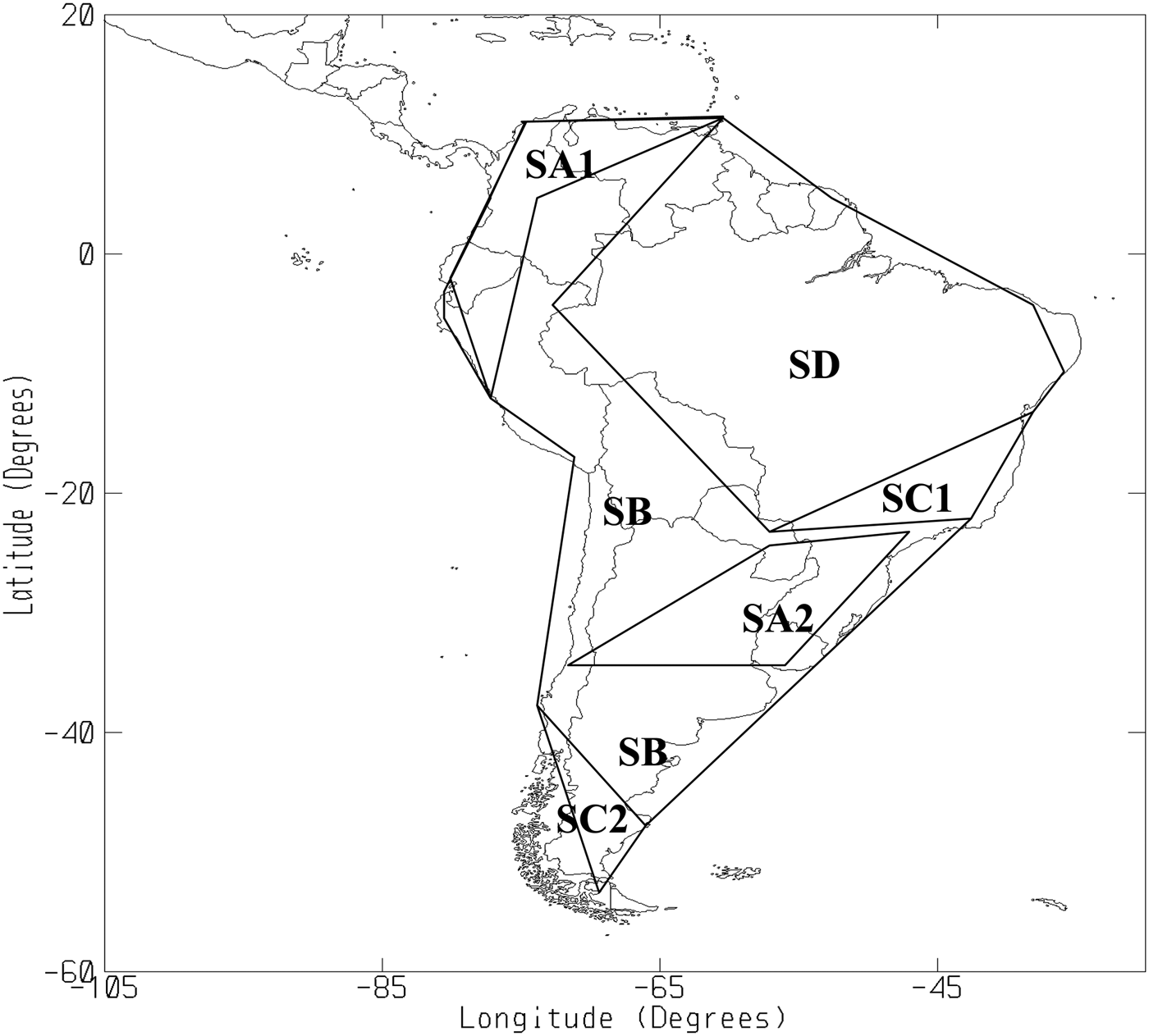
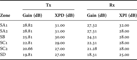
The top floor PAN_S_TXRX antenna that provides DBS service to South America from the AMAZONAS spacecraft (placed in the geostationary orbit at 61° West) has been selected as a reference to define the requirements. The coverage is divided in several zones as shown in Fig. 1, with different requirements of gain and cross-polarization, as shown in Table 1. Cross-polar discrimination (XPD) is specified for transmission and cross-polar isolation (XPI) for reception. These requirements are the same as defined in [Reference Encinar, Arrebola, Fuente and Toso12] for the three-layer reflectarray antenna, and should be accomplished in dual-linear polarization, vertical (V) and horizontal (H), being H-polarization defined with the electric field parallel to the equatorial plane. The antenna is oriented with its y-axis parallel to the equator, so that the radiated electric field polarized in the x-axis of the antenna will be vertical, and that polarized in the y-axis will be horizontal.
Coverage of PAN-S mission in Amazonas Satellite.
Gain and cross-polarization requirements for V- and H-polarization.
B) Definition of reflectarray cells
The reflectarray cells are based on four dipoles for each polarization in two layers, see Fig. 2. The cell contains two sets of dipoles displaced one from each other. Each set consists of three coplanar parallel dipoles printed on a dielectric layer and a fourth parallel dipole, which is stacked with the central one and is printed on the opposite side of the same dielectric sheet. In the case of X-polarization, the three horizontal parallel dipoles are printed on the top surface of the layer and the fourth dipole on the bottom surface, while the placement of the dipoles for Y-polarization is the other way round.
Reflectarray element based on four parallel dipoles for each polarization in two levels of metallization.
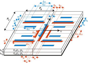
The reflectarray cells are analyzed in a periodic environment using a home-made software based on the Method of Moments in the Spectral Domain (MoM-SD) and using multilayered Green's functions for periodic structures, as described in [Reference Mittra, Chan and Cwik14]. The technique has been implemented for an arbitrary number of dipoles with different orientation in several layers. The analysis toll accounts for the losses in the dielectrics, but not in the conductors. It was checked by simulations that the losses in the dipoles or ground plane made of copper are negligible at these frequencies. The geometrical parameters have been chosen to provide a smooth phase response in Tx and Rx frequencies. The lay-up of the reflectarray and the properties of the dielectric layers are shown in Table 2 and the period is P X = 10 mm, P Y = 12 mm. Assuming all the dipoles have the same width (w = 0.5 mm), and the same separation between dipoles of the same group (SA, SB, center to center), it has been found that a linear phase response and a broadband performance is achieved when the ratios between the lengths of dipoles for each polarization are:
 $$l_{A2} = l,\;l_{A1} = l_{A3} = 0.58l,\;l_{A4} = l,\;{\rm S}_A = 2.5\;{\rm mm,} $$
 $$\eqalign{& l_{B2} = 0.93l,\;l_{B1} = l_{B3} = 0.63l,\;l_{B4} = 0.95l, \cr & {\rm S}_B = 2.5\;{\rm mm}.}$$
Reflectarray lay-up including nominal and measured properties of the materials.

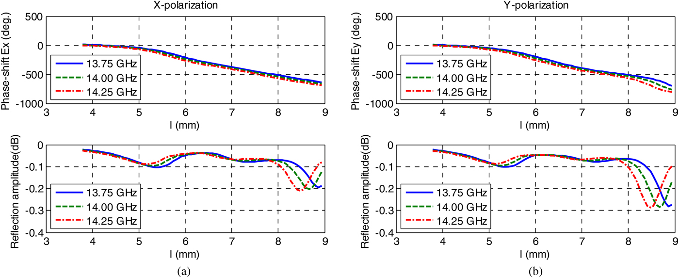
Assuming the ratios given in (1) and (2), the phase and amplitude curves have been evaluated for both polarizations in Tx and Rx frequencies for different angles of incidence, while using the nominal values of permittivity and loss tangent provided by the manufacturer. The phase and amplitude curves at 11.95, 11.3, and 12.6 GHz are shown in Fig. 3 and at 13.75, 14.0, and 14.25 GHz in Fig. 4, assuming an angle of incidence θ = 25°, φ = 40°. Similar curves are obtained for other incidence angles. The simulations show a linear phase response in both frequency bands and losses below 0.2 dB for most cases of dipole lengths and angles of incidence. The cross-polarization has also been evaluated for the worse case (θ = 25°, ϕ = 40°) and represented in Fig. 5 in both frequency bands. The cross-polarization coefficients are below −15 dB in most cases. Losses and cross-polarization are slightly higher when the dipole lengths l A2 and l A4 are larger than 8 mm.
Magnitude and phase response as a function of dipole length for oblique incidence (θ = 25°, φ = 40°) at Tx frequencies (11.95, 11.3, and 12.6 GHz) for X- and Y-polarization.

Magnitude and phase response as a function of dipole length for oblique incidence (θ = 25°, φ = 40°) at Rx frequencies (13.75, 14.0, and 14.25 GHz) for X- and Y-polarization.
Magnitude of cross-polarization for both polarizations as a function of dipole length for oblique incidence (θ = 25°, φ = 40°) at Tx (a) and Rx (b) frequency bands.

C) Definition of antenna breadboard
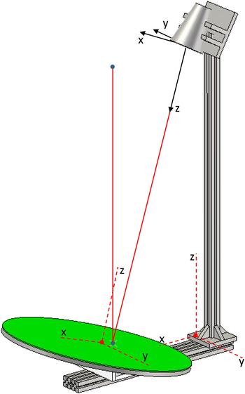
The antenna configuration is an elliptical reflectarray panel with axes 1110 mm × 1090 mm. The reflectarray cells previously described are arranged in a rectangular grid of 110 × 90 for X-polarization and 109 × 89 for Y-polarization. The antenna contains a total of 7720 elements for X-polarization. The feed for the reflectarray is a circular corrugated horn designed, manufactured, and tested by CASA-Espacio (Airbus Defence and Space) [Reference Encinar, Arrebola, Fuente and Toso12]. The center of horn aperture is placed at coordinates (−366, 0, 1451) mm, with respect to the center of the reflectarray panel, see Fig. 6. This antenna configuration provides illumination levels of −14 dB in Tx and −18 dB in Rx at the antenna edge.
Drawing of reflectarray antenna demonstrator including the coordinate systems.
D) Design and optimization
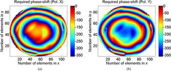
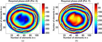
Using the spherical mode expansion for the corrugated horn, the phase distribution required to produce the prescribed coverage has been obtained at different frequencies by applying the phase-only pattern synthesis based on the Intersection Approach technique [Reference Bucci, Franceschetti, Mazzarella and Panariello15]. The resulting phase distribution at 11.95 GHz is shown in Fig. 7. A phase shift of 180° has been introduced in X-polarization with respect to Y-polarization, in order to allocate some extra room for the dipoles in the orthogonal polarization. First, the reflectarray is designed to provide these phase distributions at 11.95 GHz by using the MoM-SD tool and assuming local periodicity. Then the resulting antenna is analyzed at 14 GHz and the phase distribution is used as starting point for the pattern synthesis in Rx band. The resulting phase distributions for each polarization are shown in Fig. 8 at 14 GHz.
Synthesized phase distribution on the reflectarray at 11.95 GHz when considering the spherical mode expansion for the incident field of the horn for X-polarization (a) and Y-polarization (b).
Required phase shift at 14.00 GHz for X-polarization (a) and Y-polarization (b).
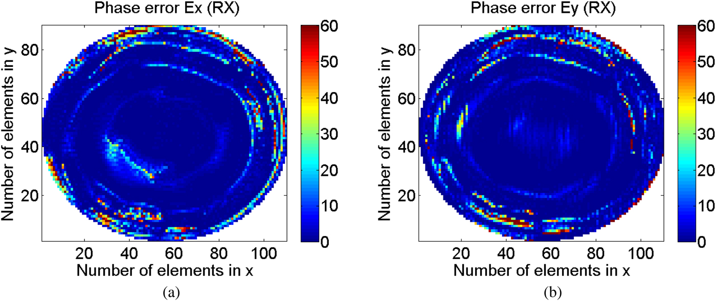
The dipole dimensions obtained in the design at 11.95 GHz are used as starting point in an optimization run, in which the dipole lengths are optimized to match simultaneously the required phases at central frequency and the phase differences at extreme frequencies in both Tx and Rx bands using a Fletcher Powell technique, as described in [Reference Encinar, Arrebola, Fuente and Toso12]. The optimization is run for each reflectarray cell, in the 7772 cells of the antenna. The optimization of the whole antenna takes 30 h in a laptop with Intel core i7-3770K and 16 GB of RAM. After the first optimization run, the errors in phase and phase differences have been reduced for both polarizations in most part of the reflectarray elements, but there are some remaining errors mostly at the extreme frequencies in Tx (11.7 and 12.2 GHz). To improve the antenna performance, the pattern synthesis and optimization processes were repeated as follows: the phases produced by the optimized reflectarray in Tx and Rx frequencies were used as a new starting point for a next pattern synthesis, and the resulting phases were used as the objective in a second optimization run of the dipole lengths. After the second optimization of the dipoles, an improvement of phase errors was observed. The requirements were met in more than 90% of the coverage zones in the worst case (see Fig. 1 and Table 1) for Tx and more than 98% for Rx frequencies. In order to improve the requirement compliance, the process was repeated a third time, but it was observed that after the second iteration, the improvement in the performances is practically negligible. The errors in phase after the third iteration of the optimization process are shown in Figs 9 and 10 for Tx and Rx frequencies and both polarizations. Note that the errors in phase are always small, <20° in most part of the surface.
Errors in phase at central frequency of Tx (11.95 GHz) for X-polarization (a) and Y-polarization (b).
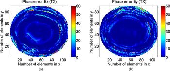
Errors in phase at central frequency of Rx (14.00 GHz) for X-polarization (a) and Y-polarization (b).
The designed reflectarray antenna demonstrator has been analyzed at central and extreme frequencies in Tx and Rx. Each element in the reflectarray antenna is analyzed using MoM-SD and local periodicity. The reflected tangential electric and magnetic fields are computed on each cell, considering the incident field on the reflectarray obtained as an expansion of spherical modes of the field radiated by the corrugated horn. The fields on the surface of the reflectarray are used to compute the radiation patterns using the First Principle of Equivalence. The co-polar and cross-polar radiation patterns have been computed and they are in agreement with the requirements specified in Table 1. The average simulated losses in the dielectric layers are <0.1 dB and the losses on the conductors are negligible at these frequencies.
III. MANUFACTURE OF REFLECTARRAY DEMONSTRATOR
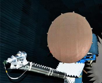
The printed arrays have been manufactured in three pieces by photo-etching the two faces of Diclad 880B 1.524 mm thick covered by copper 18 µm thick. The three panels were correctly aligned and bonded to the grounded dielectric AD255C using a 38 µm thick thermoplastic bonding film (Cuclad 6250). The reflectarray sandwich with the two dielectric layers and the bonding film was placed between two aluminum plates with alignment pins, placed in a vacuum bag and cured in an oven. The bonding film was simulated in the analysis tool, assuming the dielectric properties provided by the manufacturer, see Table 2, but its effect is negligible. Once the two layers were bonded, the ground plane of the reflectarray was glued to a 20 mm thick aluminum plate using double-face bonding tape from 3 M, to ensure the reflectarray flatness in the antenna. Finally, the feed horn was correctly positioned by using a supporting structure, as shown in Fig. 2. Figure 11 shows the final reflectarray demonstrator in anechoic chamber of the Technical University of Madrid (UPM).
Reflectarray demonstrator in the UPM anechoic chamber.
IV. COMPARISON OF MEASURED AND SIMULATED RADIATION PATTERNS
The measured radiation patterns are compared with those obtained by the analysis tool developed by UPM based on MoM-SD and local periodicity using the nominal values of permittivity and loss tangent provided by the manufacturer. A good agreement is observed in the co-polar contour lines above 15 dBi covering the different zones of the coverage, but there are some discrepancies that can be attributed to a large tolerance in the dipole dimensions, and a variation in the dielectric properties of the materials.
The dipole dimensions obtained from the optimizations were enlarged 60 µm in the photo masks to try to compensate for underetching. When the printed arrays were finished, the dimensions of some selected dipoles were measured, showing that the average dimensions are 60 µ larger than the nominal values, which means that practically there was no underetching. To account for the dipole tolerances in the simulations, all the dipole dimensions have been increased to 60 µm plus a random variation between ±20 µm.
We have measured the permittivity and loss tangent of the two materials used in the demonstrator, by measuring the reflection coefficient in a short-ended rectangular waveguide (WR62) filled with slices of material for several lengths as described in [Reference Page16]. A set of pieces were introduced in the waveguide section to obtain different lengths. A short circuit was used to close the waveguide just at the end of the filled section. The measurement with different lengths provides the values of the complex permittivity in a broadband (from 12.5 to 18 GHz for WR62). The measured values have been added to Table 2. Note that the discrepancy in εr is around 6%, but the measured tan δ is between two and three times the nominal value.
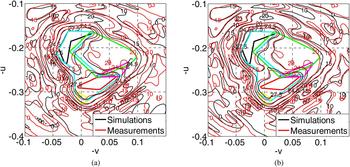
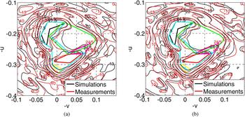
The radiation patterns have been computed again by using the measured values of εr and tan δ, and accounting for the dimensional errors. It has been checked that the effect of variation εr and tan δ produce a larger impact in the radiation patterns than the dimensional errors. Figures 12–15 show the contoured-line radiation patterns obtained for nominal and corrected values for both polarizations at two frequencies within the Tx and Rx bands. The results are in much better agreement in the co-polar patterns after the correction. To avoid this problem, εr and tan δ can be accurately extracted from the measurements of the reflectarray cells in waveguide simulator [Reference Hannan and Balfour17], and the measured values of εr and tan δ should be used in the optimization of the reflectarray cells.
Comparison of simulated and measured gain contours considering nominal values (a) and accounting for tolerances and measured electrical properties (b) for X-polarization at 11.70 GHz.
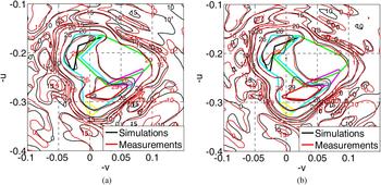
Comparison of simulated and measured gain contours considering nominal values (a) and accounting for tolerances and measured electrical properties (b) for Y-polarization at 11.70 GHz.
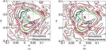
Comparison of simulated and measured gain contours considering nominal values (a) and accounting for tolerances and measured electrical properties (b) for X-polarization at 14.00 GHz.
Comparison of simulated and measured gain contours considering nominal values (a) and accounting for tolerances and measured electrical properties (b) for Y-polarization at 14.00 GHz.
V. COMPARISON WITH THREE-LAYER REFLECTARRAY
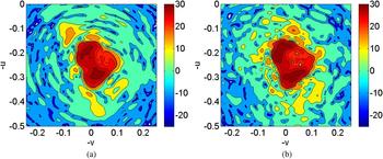
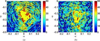
The measured co-polar discrimination and XPD patterns are represented in Figs 16 and 17 for the demonstrator described here and for the three-layer reflectarray reported in [Reference Encinar, Arrebola, Fuente and Toso12] for X-polarization at 11.7 GHz. To make the comparison easier, the same levels and colors are represented for both demonstrators. The comparison of both results shows that the co-polar coverage and the XPD are better accomplished in the new demonstrator than in the three-layer reflectarray. Similar conclusions are obtained when comparing the patterns for other frequencies in both polarizations.
Measured radiation patterns at 11.7 GHz for X-polarization for the demonstrator made of dipoles (a) and for the three-layer reflectarray [Reference Encinar, Arrebola, Fuente and Toso12] (b).
Measured XPD at 11.7 GHz for X-polarization for the demonstrator made of dipoles (a) and for the 3-layer reflectarray reported in [Reference Encinar, Arrebola, Fuente and Toso12] (b).
In addition, the manufacturing complexity has been simplified. Whereas the previous demonstrator required three stacked layers with printed patches, the reflectarray proposed here requires only two layers of printed arrays with dipoles. In the implementation made for the demonstrator, only one bonding film was required. For space technology, two layers of honeycomb and two layers of kapton with printed dipoles are desirable. In any case, the number of layers has been reduced and the electrical performance has been improved.
VI. CONCLUSIONS
A 1.1 m reflectarray demonstrator made of two layers of printed dipoles has been designed, manufactured and tested to fulfill the requirements of a South-American coverage in Tx and Rx. The performance of this antenna has been compared with that obtained for a 1.2 m reflectarray made of three layers of stacked patches. The comparison shows that the new reflectarray performs slightly better than the previous one, in spite of the smaller number of layers and smaller antenna size. The results presented here have demonstrated the viability of this technology with very promising capabilities for Ku-band TX/RX antennas in communication satellites.
ACKNOWLEDGEMENTS
This work has been supported by the Spanish Ministry of Economy and Competitiveness under the project TEC2016-75103-C2-1-R, by “Junta de Andalucía” (project P12-TIC-1435) and by the European Space Agency (ESA) under contract 4000117113/16/NL/AF. The authors express their gratitude to Airbus Defence and Space, Madrid, for providing the antenna requirements.
 José A. Encinar received the Master's and Ph.D. degrees on the Electrical Engineering, both from the Universidad Politécnica de Madrid (UPM), in 1979 and 1985, respectively. Since 1991 he is a full professor at UPM. He is currently with the “Information Processing and Telecommunications Center” from UPM. His research interests include numerical techniques for the analysis of multilayer periodic structures, design of frequency selective surfaces, printed arrays, and reflectarrays. Prof. Encinar has co-authored more than 200 journal and conference papers, one book and several book chapters. He is a holder of five patents on array and reflectarray antennas. He was a co-recipient of the 2005 H. A. Wheeler Applications Prize Paper Award and the 2007 S. A. Schelkunoff Transactions Prize Paper Award, given by the IEEE Antennas and Propagation Society. He is an IEEE Fellow since 2010.
 Rafael Florencio received the Licenciado degree in Physics from the University of Seville, Seville, Spain, in 2008, and the Master's degree in Communications Technology and Systems and the Ph.D. degree in Telecommunications Engineering from the Polytechnic University of Madrid, Madrid, Spain, in 2010 and 2016, respectively. His current research interests include the efficient design of dual-polarization dual-frequency reflectarray antennas for satellite applications. Dr. Florencio was a recipient of a Scholarship financed by the Junta de Andalucía to carry out his Ph.D. thesis.
 Manuel Arrebola received the Master's and Ph.D. degrees in Electrical Engineering from the Universidad de Málaga (UMA) in 2002, and from the Universidad Politécnica de Madrid (UPM) in 2008, respectively. From 2003 to 2007, he was with the Electromagnetism and Circuit Theory Department at UPM as a Research Assistant. Since 2007, he has been with the Electrical Engineering Department at the Universidad de Oviedo, Spain, where he is currently an Associate Professor. His current research interests include analysis, design and optimization techniques of contoured-beam and reconfigurable printed reflectarrays both in single and dual-reflector configurations, and planar antennas. Dr. Arrebola has co-authored more than 100 peer-reviewed journal and conference papers. He was a co-recipient of the 2007 S.A. Schelkunoff Transactions Prize Paper Award, given by the IEEE Antennas and Propagation Society.
 Miguel Alejandro Salas Natera is an Electrical Engineer major in Telecommunications. He received the Master's degree in Space Technologies and the Ph.D. degree in Technologies and Communications Systems, both from the Universidad Politécnica de Madrid since 2011. Dr. Miguel Salas is a Postdoc Researcher in the Applied Electromagnetism Group in the ETSIT-UPM and a Adjunct Professor in the EPS-UAM. He has participated and led in a number of international projects on the development of new antenna technologies, ground segment solutions, and antenna test and validation ranges for the aerospace and defense industry as well as on the design of active antenna arrays and on the development of novel uncertainty analysis and calibration methods. His research interests mainly within the satellite communication systems field include the analysis, design, and characterization of antenna systems such as compact reflector antennas, the development of reflectarrays antenna systems and the design, characterization, and calibration of active antenna arrays.
 Mariano Barba was born in Murcia, Spain. He received the Ingeniero de Telecomunicación and Ph.D. degrees from the Universidad Politécnica de Madrid, Madrid (UPM), Spain, in 1990 and 1996, respectively. From 1991 to 1994 he was with the Depto. de Electromagnetismo y Teoría de Circuitos (UPM), as a Postgraduate Researcher. During this time, he developed numerical methods and algorithms to characterize and design microwave passive devices. From 1994 to 2002, he has been involved in the R&D departments of several companies and institutions developing antennas and microwave circuits for space and terrestrial communication applications. In 2002, he joined the “Depto. de Electromagnetismo y Teoría de Circuitos”, (UPM) as an Associate Professor. His research interests include the analysis, characterization, and design of the antenna and microwave circuits. He is currently involved in the development and design of multibeam and reconfigurable antennas.
 Juan E. Page was born in Madrid, Spain, in 1946. He received the Ingeniero de Telecomunicación and Doctor Ingeniero degrees from the Universidad Politécnica de Madrid, Madrid, Spain, in 1971 and 1974, respectively. Since 1983, he has been a Professor with the Departamento de Electromagnetismo y Teoría de Circuitos, Universidad Politécnica de Madrid, Madrid, Spain. His current activities include the teaching of electromagnetic and circuit theories and research in the field of computer-aided design of microwave devices.
 Rafael R. Boix received the Licenciado and Doctor degrees in Physics from the University of Seville, Spain, in 1985 and 1990 respectively. Since 1986, he has been with the Electronics and Electromagnetism Department, University of Seville, where he became Tenured Professor in 2010. His current research interests are focused on the efficient numerical analysis of periodic planar multilayered structures with applications to the design of frequency selective surfaces and reflectarray antennas.
 Giovanni Toso received the Laurea Degree (cum laude) and the Ph.D. from the University of Florence, Italy, in 1992 and 1995. Since 2000, he is with the Antenna and Submillimeter Section of the European Space Agency, ESA ESTEC, Noordwijk, The Netherlands. He has been initiating and contributing to several R&D activities on satellite antennas based on arrays, reflectarrays (passive and reconfigurable), constrained lenses, and reflectors. G. Toso has co-authored more than 300 technical papers published in peer-reviewed journals and international conferences, and holds 15 international patents. G. Toso has been coauthoring the best paper at the 30th ESA Antenna Workshop and the most innovative paper at the 30th and 36th ESA Antenna Workshops. In 2014, he has been guest editor of the Special Issue on Innovative Phased Array Antennas published in the IEEE Transactions on Antennas and Propagation and, for the same society, has been an Associate Editor (2013–2016).



