





Introduction
Advancements in electromagnetic applications have led to the need to explore and utilize a wider frequency spectrum. Consequently, designing simple, lightweight, and cost-efficient antennas capable of covering large bandwidths has become highly desirable for several applications [Reference Malhotra and Basu1–Reference Chen, Liu, Nakano, Qing and Zwick3].
The sinuous antenna is a design that exhibits these desirable characteristics. First introduced and patented by DuHamel in 1987, the four-arm sinuous antenna (FASA) features a planar or conical self-complementary structure consisting of four zigzagging arms [Reference DuHamel4]. This unique configuration combines elements of log-periodic and spiral antenna designs, enabling it to generate ultra-wideband (UWB) radiation patterns with diverse polarization capabilities. These attributes make the FASA highly suitable for various UWB applications, including remote sensing of longitudinal metallic targets such as wires and missiles, ground-penetrating radars, and microwave imaging systems [Reference Pastorino5–Reference Crocker and Scott9]. The standard FASA, as designed by DuHamel, requires a sophisticated coaxial line feeding network to excite the antenna. Other types of feeding networks have been proposed in [Reference Vahdani and Begaud10–Reference Sammeta and Filipovic15] and the exponential tapered microstrip type is found to be the simplest and most applicable type of feeding network [Reference Crocker and Scott8, Reference Jafargholi and Kamyab16–Reference Zheng, Gao, Yin, Luo, Yang, Hu, Ren and Qin20]. However, the configuration of the standard FASA requires modifications to the feed region of the sinuous arms when employing an exponentially tapered microstrip feeding network.
This article presents a feeding network with improved return loss and isolation. The network is designed, fabricated, and utilized to excite the antenna. In [Reference Jafargholi and Kamyab16], the modification involved placing paired arms on opposite sides of the substrate, which could negatively impact antenna performance. In contrast, the approach implemented in this work positions all four arms on one side of the substrate, with pins used to connect the feeding network to the modified arm regions. This configuration improves the antenna radiation pattern and the return loss. Furthermore, another performance improvement involves addressing the sharp edges created by the outer truncation of the arms, as noted in [Reference Crocker and Scott8]. A new truncation method is proposed, replacing sharp edges with smooth curves, which significantly improve the return loss at lower frequencies.
The primary contribution of this article is the design of a novel sinuous antenna tailored specifically for microwave imaging applications. In various microwave imaging scenarios [Reference Pastorino5, Reference Kurtoglu, Cayoren and Cavdar6, Reference Akinci, Caglayan, Ozgur, Alkasi, Ahmadzay, Abbak, Cayoren and Akduman21], the ability to excite targets with two orthogonal linear polarizations and subsequently isolate these polarizations during measurements is often necessary or preferred. This enables imaging algorithms to operate on two orthogonal slices, improving target characterization. Additionally, a unidirectional radiation pattern with UWB characteristics is a common requirement in many such applications [Reference Abbak, Akinci, Cayoren and Akduman22]. To achieve a unidirectional radiation pattern with a sinuous antenna, a metallic cavity filled with absorbing material is placed on the backside of the antenna to suppress back-side radiation. During the design phase, the size and depth of the metallic cavity were optimized to minimize overall weight while ensuring a unidirectional radiation pattern across the desired frequency band. Subsequently, prototypes of the antenna and the feeding network were fabricated, soldered together, and integrated with the absorber-filled metallic cavity. The simulated and measured scattering parameters showed good agreement, and the measured results showed an improved return loss compared to [Reference Jafargholi and Kamyab16] in the 2–5 GHz frequency range.
To validate the dual linear polarization (DLP) capability of the antenna, a measurement system was set up in an anechoic chamber, comprising the designed four-arm cavity-backed sinuous antenna (FACBSA) and a standard linearly polarized double-ridged broadband horn antenna. The antennas were positioned at a far-field distance, with measurements taken by horizontally and vertically orienting the horn antenna while keeping the sinuous antenna fixed. The measured results of the  $S_{21}$ parameter demonstrated co- and cross-polarization depending on the orientation of the horn and sinuous antennas, confirming the DLP property of the design. Additionally, the maximum gain at the boresight of the FACBSA was measured, showing strong agreement with the simulated results.
Design of the four-arm cavity-backed sinuous antenna (FACBSA)
The standard FASA design
The sinuous antenna is created with N arms consisting of  $P$ cells scaled in dimensions with respect to each other. The $P$th cell can vary from the biggest, first, and outermost cell to the smallest and innermost cell $P$, where $R_p$ represents the outer radius of the $P$th cell. The sinuous curve generated for the $P$th cell is defined in polar coordinates $(r,\phi)$ by the equation:
 \begin{equation}
\phi = \left({-1} \right)^p \alpha _p \sin \bigg[\frac{180ln \left(r/R_p \right) }{ln \left(\tau_p\right)}\bigg] \pm \delta,
\end{equation}
\begin{equation}
\phi = \left({-1} \right)^p \alpha _p \sin \bigg[\frac{180ln \left(r/R_p \right) }{ln \left(\tau_p\right)}\bigg] \pm \delta,
\end{equation} where  $ R_{p+1} \leq r \geq R_p $ defines the inner and outer radius of the curve. In (1), $\alpha_p$ represents the angular width of the $P$th cell, $\tau_p$ is the growth rate or the ratio of the inner and outer radius of cell $P$, i.e., $ R_{p+1} = \tau R_p$. The sinuous curve is considered log-periodic if $\tau$ and $\alpha$ are constant and as quasi-log periodic if $\tau_p$ and $\alpha_p$ are depend on the cell number. Figure 1(a) shows the design parameters required to generate a single sinuous curve. Constructing the sinuous arm from the curve requires the addition of a new parameter $\delta$, and a single arm can be generated by rotating the curve $\pm \delta$ as shown in Fig. 1(b). Setting $\delta = 22.5^\circ$ produces a self-complimentary geometry, an important property for the input impedance to have a real and frequency independent characteristic [Reference Huffman and Cencich23].
Geometry and design parameters of the standard FASA: (a) the sinuous curve, (b) single sinuous arm and (c) standard FASA geometry.

The additional arms of the antenna are created by rotating the initial arm by  $90^\circ$, $180^\circ$, and $270^\circ$, resulting in four arms. Opposite pairs of arms are excited, forming a two-port geometry. The final configuration of the standard FASA is shown in Fig. 1(c), where $D_{out}$ represents the outer diameter and $D_{in}$ represents the inner diameter of the opposite arms. The lower operating frequency of the antenna can be reduced by increasing the outer diameter, while the upper operating frequency can be increased by decreasing the inner diameter, and vice versa.
The input impedance equation for the N-arm sinuous antenna is given by:
 \begin{equation}
Z = \frac{60 \pi}{sin \big( \frac{180}{N}\big)}.
\end{equation}
\begin{equation}
Z = \frac{60 \pi}{sin \big( \frac{180}{N}\big)}.
\end{equation} For an infinite four-arm self-complimentary antenna ( $\delta = 22.5^\circ$) with appropriate excitation, the average input resistance over the desired band is approximately 267 $\Omega$s. However, when the antenna is fabricated on a substrate, the input impedance is lower because of the dielectric properties of the substrate. In [Reference Salem24], an investigation of various substrates with different dielectric properties and thicknesses was carried out. It was found that a 0.254 mm Duriod substrate caused minimal performance deterioration. However, Rogers 0.81 mm (R04003C) with a relative permittivity of $\varepsilon_{r} = 3.38$ is used in this study. To evaluate the effect of the substrate on input impedance, the four arms were placed on the substrate, and the optimal average input impedance was determined by adjusting the port impedance from 267 $\Omega$ to lower values. Full-wave electromagnetic simulations were conducted in free space using the time-domain solver in CST Microwave Studio [25]. The $S_{11}$ simulation results revealed that an input impedance of 185 $\Omega$ is ideal, as it allows for the practical design of a feeding line for the balun.
Sharp-edges modification
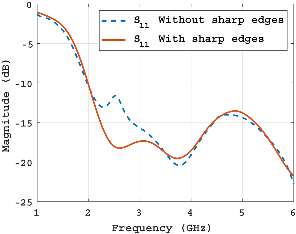
The resonance of a sinuous antenna arises from two sources: the log-periodic structure of the arms and the sharp edges formed by the truncation of the outer diameters of the arms. Studies on the resonance caused by these sharp edges and their impact have been discussed in [Reference Crocker and Scott8, Reference Kang and Kim26–Reference Kang and Kim28]. This sharp-edge resonance degrades the antenna’s performance, affecting its input impedance, radiation patterns, co-polarized gain, and reflection coefficients, particularly at lower frequencies. In [Reference Kang and Kim28], a modification method was proposed that involves the removal of half of the sharp ends on each arm. This paper presents a similar approach; however, instead of using a straight-line truncation, a circular-shaped curve is employed (see Fig. 2). This modification replaces the sharp tips with curved ends, aligning them with the natural bends of the arms and minimizing disruption to the antenna’s self-complementary properties. As these modifications are applied to the outer portions of the arms, they primarily affect the antenna’s lower frequency range. The  $S_{11}$ parameter results, shown in Fig. 3, demonstrates improved impedance matching at lower frequencies when the sharp edges are replaced with curved ends.
The standard FASA with modified sharp-edges.

Return loss of the standard FASA with and without sharp edges modification.

Feed-point modification
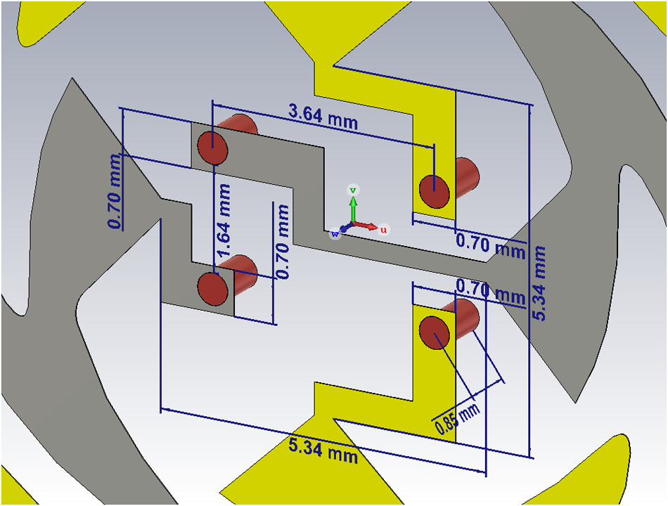
A critical consideration in designing the FASA is the connection between the arms and the feeding network. Modifications to the feed region of each arm are necessary, but these must be made carefully to preserve antenna symmetry. Various feed-point modification strategies have been proposed in [Reference Jafargholi and Kamyab16–Reference Gonnet, Sharaiha, Terret and Skrivervik18]. However, it is important to note that such modifications can result in asymmetry between the opposite arms, which may negatively impact the antenna’s performance, particularly at higher frequencies. This is because the inner diameter of the geometry, where modifications are applied, plays a crucial role in high-frequency performance. However, the fundamental properties of the antenna can be preserved with optimized modifications. The feed-point modification strategy used in this paper is shown in Fig. 4. All four arms are placed on the upper side of the substrate, with the opposite arms designated as conductors or ground for excitation. To ensure a seamless connection with the feeding network, the two positive arms are modified to have feed points on the same side, and the two ground arms are adjusted similarly. To connect the four arms to the underside of the substrate, 0.5 mm diameter pins are inserted through the substrate. The optimized values for the feed-point modifications, which provide the best antenna performance and are compatible with the feed network, are detailed in Fig. 4. These values were determined by minimizing the distance between opposite arms while maintaining a strong coupling between the ports.
Geometry and modified feeding point values.

Design of the feed network
A feeding network is essential for effectively exciting the radiating elements of a planar antenna. The design of this network depends on the required polarization and bandwidth. For the sinuous antenna, exciting only two opposite arms is sufficient to achieve single linear polarization. However, utilizing all four arms is necessary to realize DLP. Since the sinuous antenna is a wideband design with a frequency-independent input impedance, it is crucial to develop a broadband balun that maintains these characteristics while seamlessly integrating with the modified feed points of the antenna.
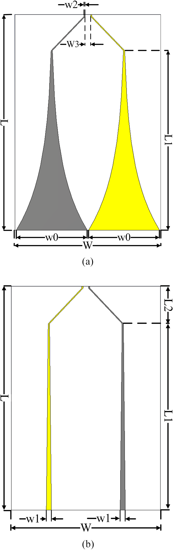
The FASA has a balanced configuration but needs to be fed using an unbalanced 50  $\Omega$ coaxial line. Initially, the antenna input impedance without a substrate is 267 $\Omega$, which decreases to 185 $\Omega$ when a substrate is added. Therefore, it is essential to design a balun to transform the unbalanced 50 $\Omega$ input impedance into a balanced 185 $\Omega$ impedance. To achieve this, an exponentially tapered microstrip balun is designed, a widely used type of balun with broadband characteristics. In such a balun, the transition from an unbalanced to a balanced line is achieved through a gradual change in the line’s cross-section, following an exponential function [Reference Kobayashi and Sawada29]. At the input (unbalanced) side, the cross-section resembles a microstrip, with the ground plane significantly larger than the width of the positive line. At the balanced output, the line transitions into a double-strip configuration, where the widths of the positive and ground strips are equal, forming a paired-strip cross-section. The width of the microstrip line at the input can be calculated using a simple formula or a microstrip line calculator. For the balanced port, the widths of the paired strips can be approximated using image theory, which suggests that the impedance of the paired strip line is twice that of the microstrip line when the strip widths are equal. Using half the distance between the two strips, the desired input impedance can be approximated. The equation of the exponential curve used to design the baluns is $y(x) = ae^{bx}$ where $a = w_1/2,$, $b = ln(w_2/w_1)/L$ for the positive line, $a = w_0/2$, $ b = ln(w_2/w_0)/L$ for the ground side, and $L$ is the length of the balun. Since there are two ports to be excited, two baluns are designed, one for each port on an FR4 substrate with $\varepsilon_{r} = 3.38$, and a thickness of 1.6 mm.
The final design of the two-port exponentially tapered microstrip balun is shown in Fig. 5(a) and (b). The outputs of both baluns are tailored to match the feed-point modifications, ensuring that they are symmetric and equal in length. This symmetry helps preserve the balanced behavior of the antenna. The dimensions of the finalized geometry are provided in Table 1. To evaluate the performance of the feeding network, the balun outputs were terminated with 185 lumped elements  $\Omega$, while a 50 $\Omega$ SMA connector was attached to the balun inputs and excited using a waveguide port to compute the scattering parameters. The simulation results showed a return loss of up to $-$15 dB and isolation better than $-$30 dB across the desired frequency band. For comparison, [Reference Aghdam, Faraji-Dana and Rashed-Mohassel17] reported a return loss of $-$12 dB with a 200 $\Omega$ output termination.
Balun geometry and design parameters: (a) ground side and (b) positive side.

Balun dimensions

The designed four-arm cavity-backed sinuous antenna (FACBSA) configuration
Adding a cavity-backed metallic reflector to the rear side of the antenna, as shown in Fig. 6(a), transforms its radiation pattern from bidirectional to unidirectional, which is preferred in most applications [Reference Abbak, Cayoren and Akduman30, Reference Bhattacharjee, Bhawal, Karmakar, Saha and Bhattacharya31]. To further enhance performance, the cavity is typically filled with an absorbing material to suppress back-side radiation. In this design, the cavity is filled with a preloaded ECOSORB LS-24 absorber, as depicted in Fig. 6(b). As noted in [Reference Yan and Cao32], the depth of the cavity also significantly affects the antenna’s resonance (see Fig. 6(c). The cavity depth  $H$ and diameter $D$ were optimized to achieve better performance while minimizing the antenna’s overall size. The final dimensions of the cavity-backed FASA are provided in Table 2.
The designed FACBSA: (a) antenna without absorber, (b) antenna with absorber and (c) cavity-depth and diameter parameters.

Dimensions of the FACBSA

For analysis purposes, the set of standard cuts taken at the elevation angles  $\phi = 0^\circ$ and $\phi = 90^\circ$ will be used to represent the two-dimensional radiation patterns. The standard cuts $\phi = 0^\circ$ and $\phi = 90^\circ$ from port 1 and port 2 indicate unidirectional radiation patterns due to the reduction of back radiation over the 2–5 GHz frequency band (see Figs. 7 and 8).
Radiation patterns of the FACBSA at  $\phi = 90^\circ$ and $\phi = 0^\circ$ from Port 1: (a) 2 GHz, (b) 3.05 GHz, (c) 4.1 GHz and (d) 5 GHz.

Radiation pattern of the FACBSA at  $\phi = 90^\circ$ and $\phi = 0^\circ$ from Port 2: (a) 2 GHz, (b) 3.05 GHz, (c) 4.1 GHz and (d) 5 GHz.

Fabrication and measurement of the designed FACBSA
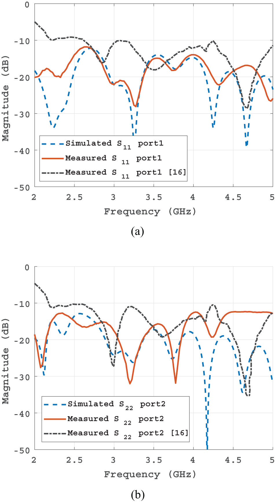
To validate the simulation results, the antenna and the feed network were fabricated and soldered together, as shown in Fig. 9(a). A metallic cavity filled with an absorber was then integrated with the antenna, as depicted in Fig. 9(b). The antenna scattering parameters were measured using the N5230A PNA series network analyzer. The simulated and measured return loss for ports 1 and 2 of the absorber-filled cavity-backed antenna are shown in Fig. 10(a) and (b), respectively. For comparison, the measured return loss of the antenna from [Reference Jafargholi and Kamyab16] is also included. The measured results align well with the simulations, showing a return loss better than  $-$12 dB for both ports while maintaining an isolation of $-$20 dB across the desired frequency band.
Fabricated antenna: (a) without metallic cavity and (b) with metallic cavity.

Measurement and simulation results compared with results in [Reference Jafargholi and Kamyab16]: (a) port 1 and (b) port 2.

Dual linear polarization measurement
A measurement setup, shown in Fig. 11, was arranged inside an anechoic chamber to evaluate the DLP property of the designed FACBSA. The setup includes the fabricated antenna and a standard linearly polarized double-ridged broadband horn antenna (BBHA 9120 A, 0.8–5 GHz) [33]. The antennas were positioned 2 meters apart, satisfying the far-field condition. Prior to measurements, the antennas were oriented such that port 1 of the sinuous antenna corresponds to the vertically oriented arm (along the  $y$-axis) and port 2 corresponds to the horizontally oriented arm (along the $x$-axis), as depicted in Fig. 11. Similarly, the horn antenna was oriented vertically or horizontally, depending on the measured port. The radiation direction for the vertically and horizontally oriented arms is along the $z$-axis, directed toward the horn antenna. Since the electric field is perpendicular to the radiation direction, the co-polarized electric fields $E_\theta$ and $E_\phi $ correspond to the $x$-axis and $y$-axis for the vertically and horizontally oriented arms, respectively. The orientation of the electric field of the horn antenna is provided in [33].
Dual linear polarization measurement setup.

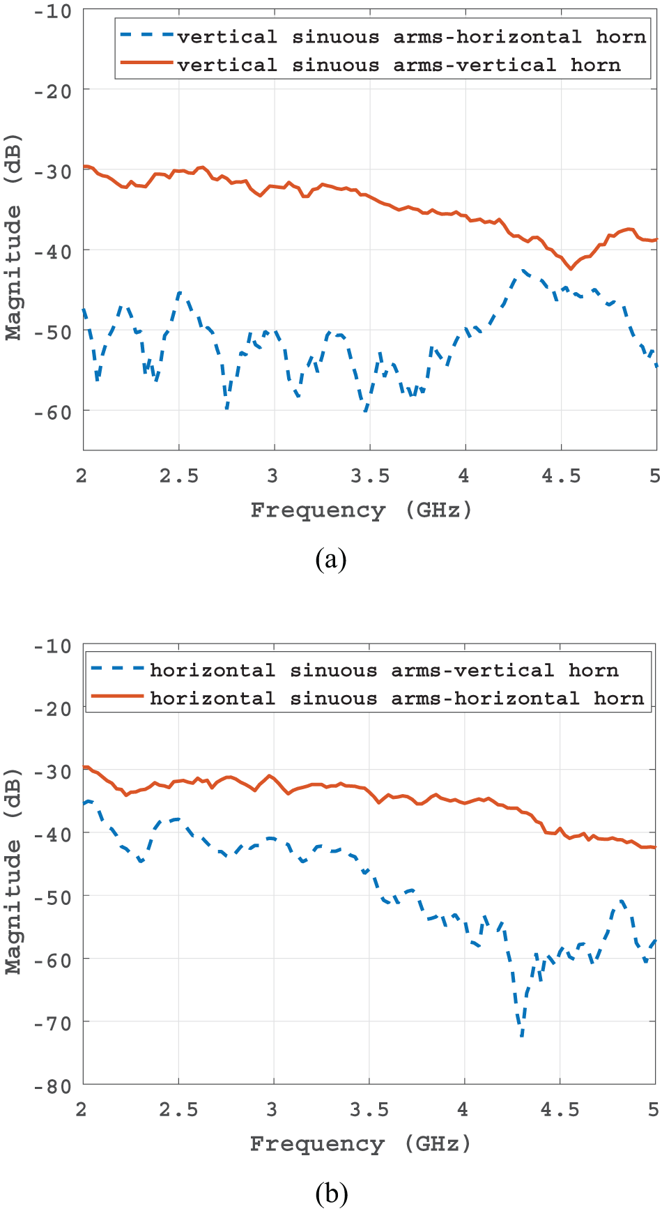
After calibrating both the sinuous and horn antennas, port 1 of the sinuous antenna was connected to port 1 of the network analyzer, while port 2 of the analyzer was connected to the horn antenna. Measurements were performed by orienting the horn antenna in two positions: first vertically, and then horizontally. Once the measurements for port 1 of the sinuous antenna were completed, port 1 of the network analyzer was connected to port 2 of the sinuous antenna. Similarly, two measurements were performed with the horn antenna oriented vertically and horizontally. The results of the measured parameter  $S_{21}$ for port 1 and port 2 of the FACBSA are shown in Fig. 12(a) and 12(b), respectively. The results indicate that port 1 of the antenna, corresponding to the vertically oriented arms, is co-polarized with the horn antenna in the vertical position and cross-polarized when the horn antenna is in the horizontal position. Conversely, port 2 of the antenna, corresponding to the horizontally oriented arms, is co-polarized with the horn antenna in the horizontal position and cross-polarized when the horn antenna is in the vertical position. These measurements clearly confirm the DLP capability of the designed FACBSA.
Measured co- and cross-polarized  $S_{21}$ results: (a) $S_{21}$ from port 1 and (b) $S_{21}$ from port 2.

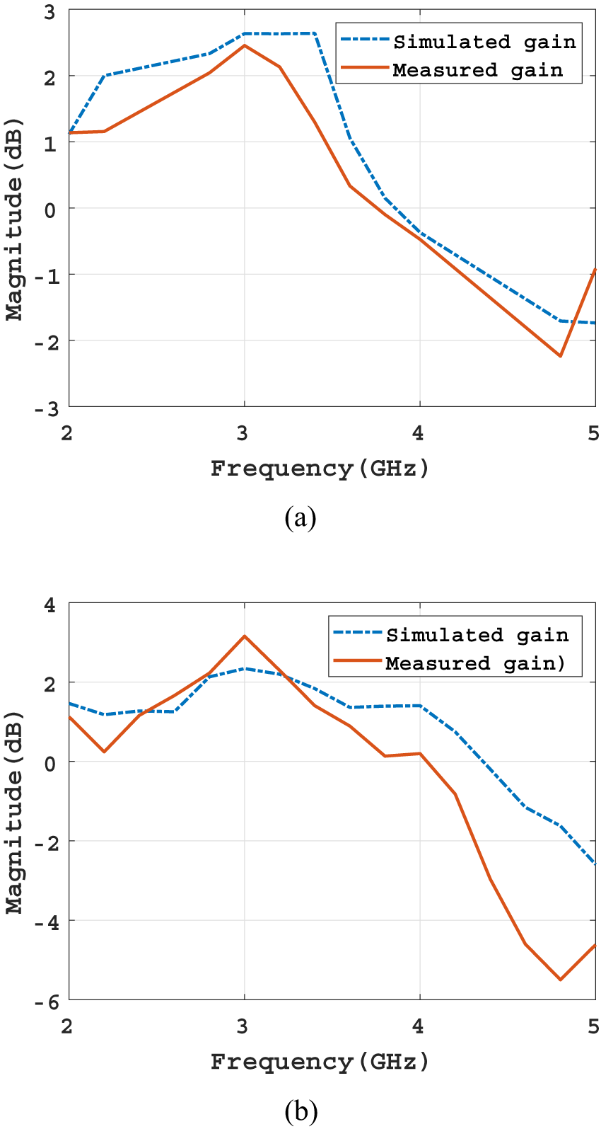
Using the calibrated horn antenna as a reference and maintaining the same measurement setup, the co-polarized parameters  $S_{21}$ were used to calculate the maximum gain in boresight. The maximum simulated and measured gain at boresight for port 1 and port 2 are presented in Fig. 13(a) and 13(b), respectively. The results show a good agreement between the simulated and measured maximum gain values.
Maximum gain at boresight vs frequency: (a) maximum gain at port 1 and (b) maximum gain at port 2.

Conclusion
This article presents a dual linear polarized cavity-backed FASA featuring novel feed-point and sharp-edge modification techniques. To address the challenges of feeding the antenna, necessary modifications are made to the feeding region. Previous studies on feed-point modifications often lacked clarity or employed methods that placed the arms on opposite sides of the substrate, negatively impacting antenna performance. This work introduces a new modification method that positions all four arms on a single side of the substrate, enabling seamless integration with an exponentially tapered microstrip line. This approach improves the antenna’s return loss, radiation pattern, and gain compared to existing designs. Additionally, a sharp-edge modification is implemented, significantly improving the return loss at lower frequencies. The designed cavity-backed FASA demonstrates a unidirectional radiation pattern and validates DLP properties.
Competing interests
The authors report no conflict of interest.

Sulayman Joof received the B.S. degree from the Department of Electronics and Telecommunication Engineering, Istanbul Technical University, Istanbul, Turkey, in 2015. The M.S. degree was obtained from the Department of Satellite Communication and Remote Sensing, Istanbul Technical University, Istanbul, Turkey. Currently, he is working towards his Ph.D. degree in the same department and also works as an RF Antenna design engineer at Mitos Medical Technologies. His research interests include antenna design, microwave dielectric spectroscopy, microwave imaging, data analysis, and wireless RF power transfer.

Mehmet Çayören received the B.Sc. degree in electrical and electronics engineering from Istanbul University, Istanbul, Turkey, in 2001, and the M.Sc. and Ph.D. degrees in electronics and communication engineering from Istanbul Technical University, Istanbul, in 2004 and 2009, respectively. From 2008 to 2009, he was a Visiting Scholar with the Department of Mathematical Sciences, University of Delaware, Newark, DE, USA. He is currently a Professor of electronics and communication engineering with Istanbul Technical University. His research interests include microwave imaging, inverse scattering, and computational electromagnetics.

Ibrahim Akduman was born in Konya, Turkey, in 1963. He received the B.Sc., M.S., and Ph.D. degrees in electronics and communication engineering from Istanbul Technical University, Istanbul, Turkey, in 1984, 1987, and 1990, respectively. He was a Visiting Scientist with the New York University Tandon School of Engineering, Brooklyn, NY, USA, in 1991; King’s College London, London, U.K., in 1995; the New Jersey Institute of Technology, Newark, NJ, USA, in 2000; and the University of Göttingen, Göttingen, Germany, in 2001. He was the Dean of the Electrical and Electronics Engineering Faculty, Istanbul Technical University, from 1999 to 2001, and a Vice President from 2002 to 2004. He is currently with Istanbul Technical University, as a Full Professor. His research interests include microwave tomography and electromagnetics in medicine. He is also a shareholder in MITOS Medical . Prof. Akduman received the Turkish Scientific and Technological Research Council Young Scientist Award in 2000.








 Open access

