


1 Introduction
Identifying the mechanisms that transport energy between electromagnetic fields and charged particles in nearly collisionless plasmas is a critical step in the broader effort to characterize and ultimately predict the dissipation of turbulence in space and astrophysical plasmas. Proposed mechanisms for energy transfer can broadly be grouped into three classes: (i) resonant mechanisms, e.g. Landau damping, Barnes damping or cyclotron damping (Landau Reference Landau1946; Barnes Reference Barnes1966; Kennel & Engelmann Reference Kennel and Engelmann1966); (ii) non-resonant mechanisms, e.g. stochastic heating by low-frequency, large-amplitude kinetic Alfvén waves (McChesney, Stern & Bellan Reference McChesney, Stern and Bellan1987; Chen, Lin & White Reference Chen, Lin and White2001; Johnson & Cheng Reference Johnson and Cheng2001; Chandran et al. Reference Chandran, Li, Rogers, Quataert and Germaschewski2010; Chandran Reference Chandran2010) or magnetic pumping (Berger et al. Reference Berger, Newcomb, Dawson, Frieman, Kulsrud and Lenard1958; Lichko et al. Reference Lichko, Egedal, Daughton and Kasper2017); and (iii) spatially localized mechanisms, e.g. magnetic reconnection at intermittent current sheets (Dmitruk, Matthaeus & Seenu Reference Dmitruk, Matthaeus and Seenu2004; Matthaeus & Velli Reference Matthaeus and Velli2011; Servidio et al. Reference Servidio, Greco, Matthaeus, Osman and Dmitruk2011; Karimabadi et al. Reference Karimabadi, Roytershteyn, Wan, Matthaeus, Daughton, Wu, Shay, Loring, Borovsky and Leonardis2013; Zhdankin et al. Reference Zhdankin, Uzdensky, Perez and Boldyrev2013; Osman et al. Reference Osman, Kiyani, Chapman and Hnat2014a,Reference Osman, Matthaeus, Gosling, Greco, Servidio, Hnat, Chapman and Phanb; Zhdankin, Uzdensky & Boldyrev Reference Zhdankin, Uzdensky and Boldyrev2015). The solar wind, a hot and diffuse plasma emanating from the Sun, serves as a natural laboratory for observing which energization mechanisms operate under what plasma conditions. A significant limitation of in situ measurements of the solar wind is that most observations occur at a single point, therefore it is not possible to assess the entire energy budget of the system. However, as different mechanisms preferentially transfer energy to particles with specific characteristic velocities, single-point observations of the velocity-space structure of the energy transfer may enable the determination of which energization mechanisms are at work.
A field–particle correlation technique (Klein & Howes Reference Klein and Howes2016; Howes, Klein & Li Reference Howes, Klein and Li2017) has been proposed to capture the velocity-space structure of energization mechanisms from single-point observations. This technique resolves the electric-field component of the field–particle interaction term in the Vlasov equation as a function of velocity and averages the energy density transfer rate over some correlation time interval. By capturing the transfer rate as a function of velocity, the regions in phase space that lose energy to or gain energy from the fields are identified. Performing a time average removes the oscillatory energy transfer between the plasma and the fields, isolating the secular component of the transfer that leads to net energization. Combined, this velocity-resolved and time-averaged transfer rate, denoted the velocity-space signature, can be used to characterize the energization mechanisms operating in a plasma measured only at a single point in space.
Previous applications of this field–particle correlation technique include numerical studies of electrostatic waves (Klein & Howes Reference Klein and Howes2016; Howes et al. Reference Howes, Klein and Li2017) and instabilities (Klein Reference Klein2017), monochromatic kinetic Alfvén waves (Howes Reference Howes2017), energization near current sheets arising from strong Alfvén wave collisions (Howes, McCubbin & Klein Reference Howes, McCubbin and Klein2018) as well as low-frequency, wavevector-anisotropic, strong turbulence (Klein, Howes & TenBarge Reference Klein, Howes and TenBarge2017). The technique has also been applied to turbulent magnetosheath plasma measured by MMS (Chen, Klein & Howes Reference Chen, Klein and Howes2019). For both simulations and observations, a clear signature of energy transfer as a function of  $v_{\Vert }$ was identified, which is indicative of significant energy being transferred via the Landau resonance. The previous numerical simulations of turbulence used AstroGK, a gyrokinetic code in which the low-frequency approximation arising through the gyroaveraging procedure eliminates the physics of the cyclotron resonance (Howes et al. Reference Howes, Cowley, Dorland, Hammett, Quataert and Schekochihin2006). In this work, we use a hybrid Vlasov–Maxwell code, HVM, to simulate higher-frequency Alfvén-ion cyclotron turbulence, a system in which proton cyclotron damping may contribute to the removal of energy from the turbulence. For the Alfvén-ion cyclotron system, both the parallel and perpendicular electric field components, $E_{\Vert }$ and $E_{\bot }$, can contribute to the energy density transfer via the Landau and cyclotron resonances, respectively. At most points throughout the simulation, resonant signatures near the proton thermal velocity, $|v_{\Vert }|\sim v_{tp}$, are associated with energization due to $E_{\Vert }$, while particles with $v_{tp}\lesssim v_{\bot }\lesssim 3v_{tp}$ couple most strongly with $E_{\bot }$. By diagnosing the energy transfer at 64 spatial points distributed throughout the simulation, we find that the energy transfer mediated by $E_{\Vert }$ after one Alfvén crossing time at these points accounts for $62\,\%\pm 24\,\%$ of the total energy transfer.
The remainder of this paper is organized as follows. An overview of the relevant damping mechanisms and the simulation code employed, HVM, is given in §§ 2 and 3. The field–particle correlation method is presented in § 4 and is applied to simulation data in § 5. In § 6, we discuss the relative importance of the electric field and advection to energy transfer, followed by conclusions in § 7. This extension of the field–particle correlation technique to a regime of higher-frequency turbulence, distinct from previous numerical studies of low-frequency turbulence, demonstrates that this technique can successfully employ single-point measurements both to distinguish distinct mechanisms of energy transfer and to determine quantitatively the rates of particle energization in each channel.
2 Energy transfer in ion-cyclotron turbulence
Collisionless resonant mechanisms that mediate energy transfer in magnetized plasmas sensitively depend on the frequency of the associated plasma fluctuations. These mechanisms require a portion of the particle velocity distribution with significant phase space density to approximately satisfy the resonance condition  $\unicode[STIX]{x1D714}(\boldsymbol{k})-k_{\Vert }v_{\Vert }-n\unicode[STIX]{x1D6FA}_{s}=0$, where $\unicode[STIX]{x1D714}(\boldsymbol{k})$ is the wavevector-dependent normal mode frequency, $k_{\Vert }$ is the component of the wavevector parallel to the mean magnetic field $\boldsymbol{B}_{0}$, $v_{\Vert }$ is the parallel particle velocity, $\unicode[STIX]{x1D6FA}_{s}=q_{s}B/m_{s}c$ is the cyclotron frequency for species $s$ and $n$ is an integer. Previous field–particle correlation work specifically focused on energy transfer in systems where the Landau, or $n=0$, resonance is the only available channel for collisionless damping, including both systems with monochromatic waves (Klein & Howes Reference Klein and Howes2016; Howes Reference Howes2017; Howes et al. Reference Howes, Klein and Li2017; Klein Reference Klein2017) and simulations of strong, wavevector-anisotropic turbulence (Klein et al. Reference Klein, Howes and TenBarge2017; Howes et al. Reference Howes, McCubbin and Klein2018).
The Landau resonance is important for low-frequency, wavevector-anisotropic fluctuations of the kind typically observed in the solar wind. A significant body of evidence, including observational (Sahraoui et al. Reference Sahraoui, Goldstein, Belmont, Canu and Rezeau2010; Chen et al. Reference Chen, Boldyrev, Xia and Perez2013; Roberts, Li & Jeska Reference Roberts, Li and Jeska2015), theoretical (Schekochihin et al. Reference Schekochihin, Cowley, Dorland, Hammett, Howes, Quataert and Tatsuno2009; Kunz et al. Reference Kunz, Schekochihin, Chen, Abel and Cowley2015, Reference Kunz, Abel, Klein and Schekochihin2018) and numerical (Howes et al. Reference Howes, Dorland, Cowley, Hammett, Quataert, Schekochihin and Tatsuno2008; Mallet, Schekochihin & Chandran Reference Mallet, Schekochihin and Chandran2015; Grošelj et al. Reference Grošelj, Mallet, Loureiro and Jenko2018) studies, suggests that magnetized collisionless turbulence is dominated by low-frequency, anisotropic Alfvénic fluctuations. However, as discussed in Cerri et al. (Reference Cerri, Califano, Jenko, Told and Rincon2016) and Arzamasskiy et al. (Reference Arzamasskiy, Kunz, Chandran and Quataert2019), the role of higher-frequency fluctuations in realistic turbulent systems is still an area of active debate. For higher-frequency fluctuations, with turbulent fluctuation frequencies at or above the proton cyclotron frequency  $\unicode[STIX]{x1D714}\gtrsim \unicode[STIX]{x1D6FA}_{p}$, collisionless damping may proceed through the $n\neq 0$ cyclotron resonances.
Eigenfunction relations for the Alfvén dispersion surface as a function of  $\boldsymbol{k}\unicode[STIX]{x1D70C}_{p}$ for a $\unicode[STIX]{x1D6FD}_{p}=1$ plasma (in which $\unicode[STIX]{x1D70C}_{p}=d_{p}$). (a) The normalized total proton damping rate $\unicode[STIX]{x1D6FE}_{p}/\unicode[STIX]{x1D714}$ from (2.1). (b) The normalized parallel phase velocity $\unicode[STIX]{x1D714}/k_{\Vert }v_{A}$. (c) The fraction of the proton damping rate due to the Landau resonance. (d) The fraction of the proton damping rate due to the cyclotron resonance. The boxes outline the wavevector ranges for HVM simulations presented here (black) and in previous gyrokinetic simulations of low-frequency, strong turbulence (red) Klein et al. (Reference Klein, Howes and TenBarge2017). The red dots indicate the values of $(|k_{\bot }|,|k_{\Vert }|)\unicode[STIX]{x1D70C}_{p}$ with initialized Alfvén waves for the HVM simulation. The grey region in the upper left-hand corner shows where $\unicode[STIX]{x1D6FE}_{p}>\unicode[STIX]{x1D714}$, and the white region in the upper right-hand corner shows where $\unicode[STIX]{x1D714}=0$.

In this work, we focus on determining the velocity-space signatures of energy transfer to the protons in higher frequency, Alfvén-ion cyclotron turbulence. In order to select a wavevector region for which cyclotron damping may be present, we consider the collisionless power absorption for the Alfvén dispersion surface as derived from linear kinetic theory. The power absorption by species  $s$ due to a normal mode with frequency $\unicode[STIX]{x1D714}(\boldsymbol{k})$ in one wave period, following Quataert (Reference Quataert1998), is given by
 $$\begin{eqnarray}\frac{\unicode[STIX]{x1D6FE}_{s}(\boldsymbol{k})}{\unicode[STIX]{x1D714}(\boldsymbol{k})}=\frac{\boldsymbol{E}^{\ast }(\boldsymbol{k})\boldsymbol{\cdot }\text{}\underline{\text{}\underline{\unicode[STIX]{x1D6EC}}}_{s}^{a}(\boldsymbol{k})\boldsymbol{\cdot }\boldsymbol{E}(\boldsymbol{k})}{4W_{\text{EM}}(\boldsymbol{k})}.\end{eqnarray}$$
 The Fourier-transformed vector electric field and its complex conjugate are given by  $\boldsymbol{E}(\boldsymbol{k})$ and $\boldsymbol{E}^{\ast }(\boldsymbol{k})$, the electromagnetic wave energy by $W_{\text{EM}}(\boldsymbol{k})$ and the anti-Hermitian part of the linear susceptibility tensor for species $s$ is $\text{}\underline{\text{}\underline{\unicode[STIX]{x1D6EC}}}_{s}^{a}(\boldsymbol{k})$. The decomposition of the power absorption by species given by (2.1) is valid as long as the total damping rate is small compared to the wave frequency $\sum _{s}\unicode[STIX]{x1D6FE}_{s}<\unicode[STIX]{x1D714}$. In figure 1(a), we use (2.1) to compute the proton power absorption for the Alfvénic dispersion surface for a proton-electron plasma with $\unicode[STIX]{x1D6FD}_{p}=8\unicode[STIX]{x03C0}n_{p}T_{p}/B^{2}=1$ and $T_{p}=T_{e}$ calculated using the PLUME dispersion solver (Klein & Howes Reference Klein and Howes2015), showing significant proton damping primarily in two regions:Footnote 1 (i) $k_{\bot }\unicode[STIX]{x1D70C}_{p}\sim 1$ (yellow) and (ii) $k_{\Vert }\unicode[STIX]{x1D70C}_{p}\gtrsim 1$ (redFootnote 2). The parallel wave phase velocity $\unicode[STIX]{x1D714}/k_{\Vert }v_{A}$ is plotted in figure 1(b), showing three general regimes: (i) the non-dispersive MHD Alfvén wave regime with $k_{\Vert }\unicode[STIX]{x1D70C}_{p}\ll 1$ and $k_{\bot }\unicode[STIX]{x1D70C}_{p}<1$ where $\unicode[STIX]{x1D714}/k_{\Vert }v_{A}=1$; (ii) the ion-cyclotron wave regime with $k_{\Vert }\unicode[STIX]{x1D70C}_{p}\gtrsim 1$ where the phase velocity decreases as $k_{\Vert }\unicode[STIX]{x1D70C}_{p}$ increases; and (iii) the kinetic Alfvén wave regime with $k_{\Vert }\unicode[STIX]{x1D70C}_{p}\ll 1$ and $k_{\bot }\unicode[STIX]{x1D70C}_{p}\gtrsim 1$ where the phase velocity increases as $k_{\bot }\unicode[STIX]{x1D70C}_{p}$ increases. Note that, for a plasma with $\unicode[STIX]{x1D6FD}_{p}=1$, the proton Larmor radius $\unicode[STIX]{x1D70C}_{p}=v_{tp}/\unicode[STIX]{x1D6FA}_{p}$ is the same as the proton inertial length $d_{p}=v_{A}/\unicode[STIX]{x1D6FA}_{p}$, as the scales can be related via $\unicode[STIX]{x1D70C}_{p}=d_{p}/\sqrt{\unicode[STIX]{x1D6FD}_{p}}$.
To quantify the relative contributions to the proton damping rate  $\unicode[STIX]{x1D6FE}_{p}$ from Landau and cyclotron damping, we recalculate (2.1) using a susceptibility tensor $\text{}\underline{\text{}\underline{\unicode[STIX]{x1D6EC}}}_{p}$ constructed using only the $n=0$ contributions (Landau damping) or $n\neq 0$ contributions to the $(x,y)$ manifold (cyclotron damping, cf. Stix (Reference Stix1992) § 11.8). This decomposition by the characteristic resonance shows that the two primary regions of significant proton damping are caused by distinct mechanisms. In figure 1(c), we plot the ratio of the Landau damping rate to the total proton damping rate $\unicode[STIX]{x1D6FE}_{p}[n=0]/\unicode[STIX]{x1D6FE}_{p}$, showing that, in the region $k_{\Vert }\unicode[STIX]{x1D70C}_{p}\ll 1$, Landau damping is dominant, so that the yellow region at $k_{\bot }\unicode[STIX]{x1D70C}_{p}\sim 1$ and $k_{\Vert }\unicode[STIX]{x1D70C}_{p}\ll 1$ in figure 1(a) is dominated by Landau damping. In figure 1(d), we plot the ratio of the cyclotron damping rate to the total proton damping rate $\unicode[STIX]{x1D6FE}_{p}[\text{cyclotron}]/\unicode[STIX]{x1D6FE}_{p}$, showing that, in the region $k_{\Vert }\unicode[STIX]{x1D70C}_{p}\gtrsim 1$, cyclotron damping is dominant, so the red and black regions at $k_{\Vert }\unicode[STIX]{x1D70C}_{p}\gtrsim 1$ in figure 1(a) is dominated by cyclotron damping.
For Landau damping of Alfvén waves in the wavevector-anisotropic region with  $k_{\bot }\unicode[STIX]{x1D70C}_{p}\sim 1$ and $k_{\Vert }\ll k_{\bot }$, the collisionless energy transfer is associated with resonant parallel phase velocities $\unicode[STIX]{x1D714}/k_{\Vert }\sim v_{A}$, which are of order $v_{tp}$ for plasmas with $\unicode[STIX]{x1D6FD}_{p}\approx 1$. For waves with $k_{\bot }\unicode[STIX]{x1D70C}_{p}\gg 1$, the parallel phase velocity of the wave increases, moving out of resonance with the thermal proton population, reducing the effectiveness of proton Landau damping. As the parallel wavevector $k_{\Vert }\unicode[STIX]{x1D70C}_{p}$ increases to unity and beyond, the parallel phase velocity decreases $\unicode[STIX]{x1D714}/k_{\Vert }\rightarrow 0$, similarly leading to a quenching of Landau damping.
For cyclotron damping, the velocity distribution evolves along circular pitch-angle contours centred about the parallel wave phase velocity, where this pitch-angle diffusion drives the distribution toward a state where it is constant along contours  $(v_{\Vert }-\unicode[STIX]{x1D714}/k_{\Vert })^{2}+v_{\bot }^{2}$ (Kennel & Engelmann Reference Kennel and Engelmann1966; Marsch & Tu Reference Marsch and Tu2001; He et al. Reference He, Wang, Tu, Marsch and Zong2015). For a spectrum of proton cyclotron waves propagating both up and down the magnetic field, with $k_{\Vert }>0$ and $k_{\Vert }<0$, this evolution leads to the formation of a quasilinear cyclotron diffusion plateau in the region with significant overlap of constant energy contours with $v_{tp}\lesssim v_{\bot }\lesssim 3v_{tp}$. The parallel structure of this plateau peaks at small $v_{\Vert }$, corresponding to higher phase-space densities near the centre of the proton distribution.
With the identification of the different regions of wavevector space  $(k_{\bot }\unicode[STIX]{x1D70C}_{p},k_{\Vert }\unicode[STIX]{x1D70C}_{p})$ in which Landau or cyclotron damping are expected to dominate, as shown in figure 1, we may now specify an appropriate wavevector range to yield significant proton cyclotron damping in a simulation of high-frequency Alfvén-ion cyclotron turbulence.
3 Hybrid simulations of Alfvén-ion cyclotron turbulence
Based upon these power absorption calculations, we select a wavevector region for which both Landau and cyclotron damping may be active. For our HVM simulation of Alfvén-ion cyclotron turbulence, we simulate a turbulent plasma in a domain over a wavevector range  $0.2\leqslant k_{\bot }d_{p}\leqslant 3.2$ and $0.2\leqslant k_{\Vert }d_{p}\leqslant 3.2$, denoted by the black box in figure 1. For comparison, the previous turbulent gyrokinetic simulations used in Klein et al. (Reference Klein, Howes and TenBarge2017) spanned $0.25\leqslant k_{\bot }d_{p}\leqslant 5.5$ under the asymptotic anisotropic conditions $k_{\Vert }\ll k_{\bot }$ of the gyrokinetic approximation, a wavevector range denoted by the red box in figure 1. To describe turbulent fluctuations with finite parallel wavevectors $k_{\Vert }d_{p}\gtrsim 1$ and ion-cyclotron frequencies $\unicode[STIX]{x1D714}\sim \unicode[STIX]{x1D6FA}_{p}$, we employ the hybrid Vlasov-Maxwell code HVM (Valentini et al. Reference Valentini, Trávníček, Califano, Hellinger and Mangeney2007). HVM self-consistently solves the Vlasov equation for ions on a uniform fixed three-dimensional (3-D) grid in physical space and a uniform fixed three-dimensional grid in velocity space (3V), coupled with an isothermal fluid description for the electrons through Maxwell’s equations. This method allows for accurate simulation of ion kinetic-scale phenomena. By employing an Eulerian approach, these simulations are able to resolve velocity-space structure without the statistical noise associated with particle-in-cell macroparticles. Since the ions are fully kinetic, we resolve ion-cyclotron frequency physics, which is outside the gyrokinetic formalism.
The simulation employs  $32^{3}$ spatial grid points and $51^{3}$ velocity grid points. The velocity grid spans $\pm 5v_{tp}$ for all three directions, and the size of the isotropic simulation cube is $L=10\unicode[STIX]{x03C0}d_{p}$. The proton plasma beta is unity, $\unicode[STIX]{x1D6FD}_{p}=1$, and the proton and electron temperatures are in equilibrium $T_{p}=T_{e}$. The uniform background magnetic field is in the $\hat{\boldsymbol{z}}$ direction, $\boldsymbol{B}_{0}=B_{0}\hat{z}$. The simulation dissipates small scale fluctuations using grid-scale resistivity by adding an $\unicode[STIX]{x1D702}J$ term into Ohm’s law. A small value for the resistivity $\unicode[STIX]{x1D702}$ has been chosen in order to achieve relatively high Reynolds numbers and to remove any spurious numerical effects due to the presence of grid-scale current sheets. The choice of this small value for the resistivity corresponds to a very small correction, confined to small scales, with the resulting dissipation electric field $\unicode[STIX]{x1D702}J$ only becoming dominant for the largest wavenumbers in the simulation.
Twelve Alfvén wave modes at the largest two spatial scales in the domain are initialized:  $\boldsymbol{k}d_{p}=(k_{x}d_{p},k_{y}d_{p},k_{z}d_{p})=(0.2,0,\pm 0.2)$, $(0,0.2,\pm 0.2)$, $(0.2,0.2,\pm 0.2)$, $(-0.2,0.2,\pm 0.2)$, $(0.4,0,\pm 0.2)$ and $(0,0.4,\pm 0.2)$. The magnetic and velocity fluctuations satisfy the magnetohydrodynamic (MHD) Alfvén wave eigenfunctions and are assigned distinct random phases $\unicode[STIX]{x1D719}_{k}\in [0,2\unicode[STIX]{x03C0}]$ for each initialized wavevector $\boldsymbol{k}$. The real amplitude of each Fourier wavevector mode is chosen so that the system will have a sufficiently strong turbulent cascade, as measured by the nonlinearity parameter, $\unicode[STIX]{x1D712}=(k_{\bot }/k_{\Vert })(\unicode[STIX]{x1D6FF}B_{\bot }/B_{0})\approx 1$; we set amplitudes $\unicode[STIX]{x1D6FF}\hat{B}_{k}=1/\sqrt{2}$ for $\boldsymbol{k}d_{p}=(0.2,0,\pm 0.2)$ and $(0.0,0.2,\pm 0.2)$, $\unicode[STIX]{x1D6FF}\hat{B}_{k}=1/4$ for $\boldsymbol{k}d_{p}=(0.2,0.2,\pm 0.2)$ and $(-0.2,0.2,\pm 0.2)$ and $\unicode[STIX]{x1D6FF}\hat{B}_{k}=1/(4\sqrt{2})$ for $\boldsymbol{k}d_{p}=(0.4,0.0,\pm 0.2)$ and $(0.0,0.4,\pm 0.2)$, which correspond to an overall initial root-mean-square amplitude of $\unicode[STIX]{x1D6FF}B_{\bot }/B_{0}=1/2$. In contrast to gyrokinetic simulations, where the significant wavevector anisotropy $k_{\Vert }\ll k_{\bot }$ allows the turbulence to be strong (i.e. $\unicode[STIX]{x1D712}\sim 1$) for $\unicode[STIX]{x1D6FF}B_{\bot }/B_{0}\ll 1$, having a system of strong turbulence for the wavevectors considered here with $k_{\Vert }\sim k_{\bot }$ requires $\unicode[STIX]{x1D6FF}B_{\bot }\sim B_{0}$.
This simulation box size was intentionally chosen to enclose wavevectors susceptible to both Landau and cyclotron resonances, allowing the application of the field–particle correlation technique to systems in which multiple heating mechanisms operate. This work does not necessarily replicate solar wind turbulence, which is typically found to have more significant wavevector anisotropies than are simulated here, as described for instance in Chen (Reference Chen2016).
The simulation was evolved to  $t_{max}=45\unicode[STIX]{x1D6FA}_{p}^{-1}$. We selected 64 points, $\boldsymbol{r}_{0}$, in the simulation’s 3-D spatial domain, producing output of the electromagnetic fields $\boldsymbol{E}^{\prime }(\boldsymbol{r}_{0},t)$ and $\boldsymbol{B}^{\prime }(\boldsymbol{r}_{0},t)$ in the simulation frame of reference as well as the 3V proton velocity distribution $f_{p}(\boldsymbol{r}_{0},\boldsymbol{v},t)$ at each of the selected points. To demonstrate that there is significant power distributed across a broadband range of frequencies, rather than being composed of a handful of monochromatic Alfvén waves, we plot in figure 2 the frequency power spectral density for the electric and magnetic field at each of the 64 spatial points. We see a broad distribution of power across frequency at each point, rather than a peak at $2\unicode[STIX]{x03C0}f_{0}/\unicode[STIX]{x1D6FA}_{p}=\unicode[STIX]{x1D714}_{0}/\unicode[STIX]{x1D6FA}_{p}$, where $\unicode[STIX]{x1D714}_{0}$ are the initialized Alfvén frequencies, $\unicode[STIX]{x1D714}_{0}(k_{\bot }d_{p}=0.2,k_{\Vert }d_{p}=0.2)=0.192\unicode[STIX]{x1D6FA}_{p}$, $\unicode[STIX]{x1D714}_{0}(k_{\bot }d_{p}=0.282,k_{\Vert }d_{p}=0.2)=0.195\unicode[STIX]{x1D6FA}_{p}$, and $\unicode[STIX]{x1D714}_{0}(k_{\bot }d_{p}=0.4,k_{\Vert }d_{p}=0.2)=0.198\unicode[STIX]{x1D6FA}_{p}$. Comparing this frequency distribution to the initial frequencies indicates significant nonlinear energy transfer from the initialized modes, producing a broadband turbulent system. The time series from which the frequency power spectra are calculated are stationary in the turbulent simulation, rather than traversing it at super-Alfvénic speeds as is typical of in situ measurements of the solar wind. As such, these single-point spectra do not capture the underlying spatial structure of the plasma fluctuations, which requires either invoking Taylor’s hypothesis, that the plasma-frame frequency is small compared to spatial advection (Taylor Reference Taylor1938; Howes, Klein & TenBarge Reference Howes, Klein and TenBarge2014), or measuring the system at multiple spatial points (Klein et al. Reference Klein, Alexandrova, Bookbinder, Caprioli, Case, Chandran, Chen, Horbury, Jian and Kasper2019).
(a,b) Frequency power spectral density for electric and magnetic fields extracted from the 64 spatial points throughout the HVM simulation used in this work (grey). The initialized frequencies  $\unicode[STIX]{x1D714}_{0}/\unicode[STIX]{x1D6FA}_{p}$ are indicated with an arrow on the left-hand side. The frequency ranges accessible to the Alfvén and fast dispersion surfaces for this simulation are indicated with horizontal arrows.

We compare the observed broadband distribution of frequencies to frequency ranges accessible to the Alfvén and fast normal mode solutions within the simulation’s wavevector range  $0.2\leqslant k_{\bot }d_{p}\leqslant 3.2$ and $0.2\leqslant k_{\Vert }d_{p}\leqslant 3.2$, calculated using the PLUME dispersion solver, see figure 13. Alfvén solutions are limited to a relatively narrow range of frequencies, $\unicode[STIX]{x1D714}/\unicode[STIX]{x1D6FA}_{p}\in [.19,1.0]$. Above this frequency, we see a significant break in the power spectral densities in figure 2, indicating that there is relatively little power in higher frequency, non-Alfvénic fluctuations. Integrating the power in the electric and magnetic fluctuations in the Alfvén and fast frequency ranges, we find that nearly 95 % of the total power is contained at Alfvénic frequencies, with less than 30 % found in the partially overlapping fast frequency range. Further discussion of wave mode identification using single-point time series can be found in appendix A.
4 Applying the field–particle correlation technique
This section provides a brief overview of the field–particle correlation technique. The field–particle correlation analysis captures how energy is transferred between charged particles and electromagnetic fields by correlating the structure of the particle velocity distribution function with the electric field. Applications of this technique to simulations have been limited to velocity distributions in one or two dimensions. Here we discuss the application of the field–particle correlation technique to three dimensional velocity distributions generated by the HVM code.
4.1 Overview of field–particle correlations
For a collisionless magnetized plasma, the Vlasov equation
 $$\begin{eqnarray}\frac{\unicode[STIX]{x2202}f_{s}}{\unicode[STIX]{x2202}t}+\boldsymbol{v}\boldsymbol{\cdot }\unicode[STIX]{x1D735}f_{s}+\frac{q_{s}}{m_{s}}\left[\boldsymbol{E}+\frac{\boldsymbol{v}\times \boldsymbol{B}}{c}\right]\boldsymbol{\cdot }\frac{\unicode[STIX]{x2202}f_{s}}{\unicode[STIX]{x2202}\boldsymbol{v}}=0\end{eqnarray}$$
 describes the time evolution of the velocity distribution function of charged particles of each species  $s$,
$s$,  $f_{s}(\boldsymbol{r},\boldsymbol{v},t)$, $q_{s}$ and $m_{s}$ are the intrinsic charge and mass respectively, and $c$ is the speed of light. Combined with Maxwell’s equations, the Vlasov–Maxwell system describes the self-consistent dynamics of a collisionless plasma. We want to measure the time rate of change of the microscopic kinetic particle energy, $W_{s}(t)\equiv \int \text{d}\boldsymbol{r}\int \text{d}\boldsymbol{v}\,m_{s}v^{2}f_{s}/2$. However, $\unicode[STIX]{x2202}_{t}W_{s}$ can only be calculated by integrating over all of 3D–3V phase space. Such a calculation is accessible to numerical simulations, but not to measurements made from a single point in coordinate space, as is typical for in situ measurements of heliospheric plasmas, such as the solar wind.
We therefore choose to track the energy density at a single point in 3D–3V phase space,  $\unicode[STIX]{x1D6E9}_{s}(\boldsymbol{r},\boldsymbol{v},t)\equiv m_{s}v^{2}f_{s}(\boldsymbol{r},\boldsymbol{v},t)/2$, and its time rate of change, which is found by multiplying the Vlasov equation by $m_{s}v^{2}/2$ and not performing any integration
 $$\begin{eqnarray}\frac{\unicode[STIX]{x2202}\unicode[STIX]{x1D6E9}_{s}(\boldsymbol{r},\boldsymbol{v},t)}{\unicode[STIX]{x2202}t}=-\frac{m_{s}v^{2}}{2}\boldsymbol{v}\boldsymbol{\cdot }\unicode[STIX]{x1D735}f_{s}-q_{s}\frac{v^{2}}{2}\boldsymbol{E}\boldsymbol{\cdot }\frac{\unicode[STIX]{x2202}f_{s}}{\unicode[STIX]{x2202}\boldsymbol{v}}-\frac{q_{s}}{c}\frac{v^{2}}{2}(\boldsymbol{v}\times \boldsymbol{B})\boldsymbol{\cdot }\frac{\unicode[STIX]{x2202}f_{s}}{\unicode[STIX]{x2202}\boldsymbol{v}}.\end{eqnarray}$$
Of the three terms on the right-hand side of (4.2), it can be shown (Howes et al. Reference Howes, Klein and Li2017) that only the electric-field term will contribute to the net transfer of energy between the electromagnetic fields and particles: the first term is zero for periodic or infinitely distant boundary conditions and does not exchange energy between the fields and the distribution; and the magnetic field in the third term does no work on the distribution.
Integrating by parts the second term over velocity yields the species current density dotted into the electric field  $\boldsymbol{j}_{s}\boldsymbol{\cdot }\boldsymbol{E}$, representing the work done by $\boldsymbol{E}$ on $f_{s}$ or vice versa. By not integrating this term, we resolve the velocity-space structure of energy density transfer. As different mechanisms preferentially energize particles with different characteristic velocities, resolving the velocity-space structure of the energy density transfer allows damping mechanisms to be differentiated using measurements from a single point in coordinate space.
In an electromagnetic system, to determine the net contribution of the parallel and perpendicular electric field to the energization of a species  $s$, we calculate the correlations
 $$\begin{eqnarray}C_{E_{\Vert }}(\boldsymbol{r},\boldsymbol{v},t,\unicode[STIX]{x1D70F})=C\left(-q_{s}\frac{v_{\Vert }^{2}}{2}\frac{\unicode[STIX]{x2202}\unicode[STIX]{x1D6FF}f_{s}(\boldsymbol{r},\boldsymbol{v},t)}{\unicode[STIX]{x2202}v_{\Vert }},E_{\Vert }(\boldsymbol{r},t)\right)\end{eqnarray}$$
 $$\begin{eqnarray}\displaystyle C_{E_{\bot }}(\boldsymbol{r},\boldsymbol{v},t,\unicode[STIX]{x1D70F}) & = & \displaystyle C\left(-q_{s}\frac{v_{\bot 1}^{2}}{2}\frac{\unicode[STIX]{x2202}\unicode[STIX]{x1D6FF}f_{s}(\boldsymbol{r},\boldsymbol{v},t)}{\unicode[STIX]{x2202}v_{\bot 1}},E_{\bot 1}(\boldsymbol{r},t)\right)\nonumber\\ \displaystyle & & \displaystyle +\,C\left(-q_{s}\frac{v_{\bot 2}^{2}}{2}\frac{\unicode[STIX]{x2202}\unicode[STIX]{x1D6FF}f_{s}(\boldsymbol{r},\boldsymbol{v},t)}{\unicode[STIX]{x2202}v_{\bot 2}},E_{\bot 2}(\boldsymbol{r},t)\right).\end{eqnarray}$$
 The unnormalized correlation of discretely sampled time series  $A$ and $B$ with uniform spacing $\unicode[STIX]{x0394}t$ at time $t_{i}$ is defined as
 $$\begin{eqnarray}C(t_{i},\unicode[STIX]{x1D70F}=N\unicode[STIX]{x0394}t)\equiv \frac{1}{N}\mathop{\sum }_{j=i-N/2}^{i+N/2}A_{j}B_{j},\end{eqnarray}$$
 with correlation interval of length  $\unicode[STIX]{x1D70F}=N\unicode[STIX]{x0394}t$. Parallel and perpendicular are defined with respect to the background magnetic field $\boldsymbol{B}_{0}$, with $\bot _{1}$ and $\bot _{2}$ denoting the orthogonal components in the plane perpendicular to $\hat{\boldsymbol{b}}=\boldsymbol{B}_{0}/|B_{0}|$. The $v^{2}$ component in the electric-field term of (4.2) is replaced by the square of the component of the velocity $v_{i}$ associated with the component of the field with which the distribution is being correlated $E_{i}$, as the net velocity integration is zero for the other two components, $v_{j}$ and $v_{k}$. By averaging over a time interval $\unicode[STIX]{x1D70F}$ longer than the characteristic timescale of the dominant oscillations, rather than calculating the instantaneous rate of change $C_{E_{l}}(t_{i},\unicode[STIX]{x1D70F}=0)=-q_{s}v_{l}^{2}E_{l}\unicode[STIX]{x2202}_{v_{l}}\,f_{s}/2$, the contribution due to any oscillatory energy transfer, which does not contribute to the net energization of the distribution, largely cancels out.
The spatial energy density transfer rate at a single point  $\boldsymbol{r}_{0}$ associated with a single component of the electric field $E_{l}$ is given by integrating over 3V velocity space,
 $$\begin{eqnarray}\frac{\unicode[STIX]{x2202}\bar{w}_{E_{l}}}{\unicode[STIX]{x2202}t}(\boldsymbol{r}_{0},t_{i},\unicode[STIX]{x1D70F})\equiv \int \text{d}\boldsymbol{v}\,C_{E_{l}}(\boldsymbol{r}_{0},\boldsymbol{v},t_{i},\unicode[STIX]{x1D70F})\end{eqnarray}$$
 and the accumulated spatial energy density transferred through time  $t$ is
 $$\begin{eqnarray}\unicode[STIX]{x0394}\bar{w}_{E_{l}}(\boldsymbol{r}_{0},t,\unicode[STIX]{x1D70F})=\int \text{d}t^{\prime }\,\frac{\unicode[STIX]{x2202}\bar{w}_{E_{l}}(\boldsymbol{r}_{0},t^{\prime },\unicode[STIX]{x1D70F})}{\unicode[STIX]{x2202}t}.\end{eqnarray}$$
 All energy density quantities are normalized to the average energy density at that point in space over the simulated time interval  $T$,
$T$,  $w_{0}(\boldsymbol{r}_{0})=\langle \int \text{d}\boldsymbol{v}\,m_{p}\boldsymbol{v}^{2}f_{p}(\boldsymbol{r}_{0},\boldsymbol{v},t)/2\rangle _{T}$, e.g. $\unicode[STIX]{x2202}_{t}\bar{w}_{E_{l}}(\boldsymbol{r}_{0},t,\unicode[STIX]{x1D70F})=\unicode[STIX]{x2202}_{t}w_{E_{l}}(\boldsymbol{r}_{0},t,\unicode[STIX]{x1D70F})/w_{0}(\boldsymbol{r}_{0})$.
4.2 Field–particle correlation implementation
Here we describe how we calculate the velocity-resolved energy density transfer rate using the simulated proton distribution  $f_{p}(\boldsymbol{r}_{0},\boldsymbol{v},t)$ and the simulation-frame fields $\boldsymbol{B}^{\prime }(\boldsymbol{r}_{0},t)$, and $\boldsymbol{E}^{\prime }(\boldsymbol{r}_{0},t)$ at a single spatial point $\boldsymbol{r}_{0}$, one of the 64 points $\boldsymbol{r}_{0}$ probed in the turbulent HVM simulation described in § 3. As discussed in Howes et al. (Reference Howes, Klein and Li2017), $\unicode[STIX]{x2202}_{t}\bar{w}_{E_{l}}$ is the same for correlations calculated using the velocity derivative of the full distribution $\unicode[STIX]{x2202}_{v_{i}}\,f_{s}$ or a perturbed distribution $\unicode[STIX]{x2202}_{v_{i}}\unicode[STIX]{x1D6FF}f_{s}$, where the perturbed velocity distribution $\unicode[STIX]{x1D6FF}f_{s}=f_{s}-F_{0,s}$ is computed by subtracting a suitably time-averaged mean velocity distribution, $F_{0,s}=\langle f_{s}\rangle _{t}$, as long as $F_{0,s}$ is an even function of velocity. Here we calculate $F_{0,p}(\boldsymbol{r}_{0},\boldsymbol{v})=\langle f_{p}(\boldsymbol{r}_{0},\boldsymbol{v},t)\rangle _{T}$ averaged over duration of the simulation $T$ and use the perturbed distribution $\unicode[STIX]{x1D6FF}f_{p}(\boldsymbol{r}_{0},\boldsymbol{v},t)$ for all of our correlation calculations.Footnote 3
The vector velocity derivatives  $\unicode[STIX]{x2202}_{\boldsymbol{v}}\unicode[STIX]{x1D6FF}f_{p}(\boldsymbol{r}_{0},\boldsymbol{v},t)$ are constructed using a centred-difference method. The time-averaged bulk fluid velocity for a given point $\boldsymbol{U}(\boldsymbol{r}_{0})=\langle \boldsymbol{v}_{b}(\boldsymbol{r}_{0},t)\rangle _{T}$ is computed using the instantaneous bulk velocity $\boldsymbol{v}_{b}(\boldsymbol{r}_{0},t)=[1/n(\boldsymbol{r}_{0},t)]$ $\int \text{d}\boldsymbol{v}\,\boldsymbol{v}f_{p}(\boldsymbol{r}_{0},\boldsymbol{v},t)$ and the instantaneous density $n(\boldsymbol{r}_{0},t)=\int \text{d}\boldsymbol{v}\,f_{p}(\boldsymbol{r}_{0},\boldsymbol{v},t)$. Both $\unicode[STIX]{x2202}_{\boldsymbol{v}}\unicode[STIX]{x1D6FF}f_{p}(\boldsymbol{r}_{0},\boldsymbol{v},t)$ and $\boldsymbol{E}^{\prime }(\boldsymbol{r}_{0},t)$ are transformed to the frame of reference moving at the average bulk flow velocity at each point, $\boldsymbol{U}(\boldsymbol{r}_{0})$. For the electric field, this requires applying the Lorentz transformation, discussed for instance in Howes et al. (Reference Howes, Klein and TenBarge2014),
 $$\begin{eqnarray}\boldsymbol{E}=\boldsymbol{E}^{\prime }+\boldsymbol{U}\times \boldsymbol{B}/c,\end{eqnarray}$$
 where  $\boldsymbol{E}^{\prime }$ is the electric field in the simulation frame, and $\boldsymbol{E}$ is the field in the average bulk flow frame. Note that, under the non-relativistic limit relevant to heliospheric plasmas, the magnetic field requires no such transformation (Howes et al. Reference Howes, Klein and TenBarge2014), i.e. $\boldsymbol{B}=\boldsymbol{B}^{\prime }$.
We define an instantaneous magnetic-field-aligned coordinate system at position  $\boldsymbol{r}_{0}$ by parallel direction $\hat{\boldsymbol{b}}(\boldsymbol{r}_{0},t)=\boldsymbol{B}(\boldsymbol{r}_{0},t)/|\boldsymbol{B}(\boldsymbol{r}_{0},t)|$ and the plane normal to $\hat{\boldsymbol{b}}(\boldsymbol{r}_{0},t)$ spanned by in-plane unit vectors $\hat{e}_{\bot 1}=\hat{\boldsymbol{x}}\times \hat{\boldsymbol{b}}(\boldsymbol{r}_{0},t)$ and $\hat{e}_{\bot 2}=\hat{\boldsymbol{b}}(\boldsymbol{r}_{0},t)\times [\hat{\boldsymbol{x}}\times \hat{\boldsymbol{b}}(\boldsymbol{r}_{0},t)]$. We rotate the proton velocity distribution $f_{p}$ and the electric-field components into this field-aligned coordinate systems. Note that, due to the large-amplitude magnetic field fluctuations required to achieve strong turbulence in this Alfvén-ion cyclotron system, it is essential to project the fields and particle velocities along the instantaneous magnetic field direction to avoid smearing out of the resulting velocity-space signatures of the energy transfer due to the variation in the magnetic field direction over the correlation interval.
Using the electric field and proton velocity distribution in the average bulk flow frame and field-aligned coordinates, we calculate the parallel and perpendicular field–particle correlations using (4.3) and (4.4), yielding the 3V velocity-space resolved correlations  $C_{E_{\Vert }}(\boldsymbol{r}_{0},\boldsymbol{v},t,\unicode[STIX]{x1D70F})$ and $C_{E_{\bot }}(\boldsymbol{r}_{0},\boldsymbol{v},t,\unicode[STIX]{x1D70F})$. We then integrate these correlations over 3V velocity space to obtain the spatial energy density transfer rates, $\unicode[STIX]{x2202}_{t}\bar{w}_{E_{\Vert }}(\boldsymbol{r}_{0},t,\unicode[STIX]{x1D70F})$ and $\unicode[STIX]{x2202}_{t}\bar{w}_{E_{\bot }}(\boldsymbol{r}_{0},t,\unicode[STIX]{x1D70F})$, according to (4.6) and integrate those quantities over time to obtain the accumulated spatial energy density changes, $\unicode[STIX]{x0394}\bar{w}_{E_{\Vert }}(\boldsymbol{r}_{0},t,\unicode[STIX]{x1D70F})$ and $\unicode[STIX]{x0394}\bar{w}_{E_{\bot }}(\boldsymbol{r}_{0},t,\unicode[STIX]{x1D70F})$, according to (4.7).
Velocity integrated correlations at a single point in the simulation domain for a range of correlation intervals  $\unicode[STIX]{x1D70F}\unicode[STIX]{x1D6FA}_{p}$, indicated in colour. (a,b) Energy density transfer rates $\unicode[STIX]{x2202}_{t}\bar{w}_{E_{\Vert }}$ and $\unicode[STIX]{x2202}_{t}\bar{w}_{E_{\bot }}$. (c,d) Accumulated energy density transferred $\unicode[STIX]{x0394}\bar{w}_{E_{\Vert }}$ and $\unicode[STIX]{x0394}\bar{w}_{E_{\bot }}$. The thick black line indicates the correlation interval $\unicode[STIX]{x1D70F}\unicode[STIX]{x1D6FA}_{p}=22.5$ used in the remainder of this work.

The next step is to determine a sufficiently long correlation time interval  $\unicode[STIX]{x1D70F}$ over which to average in order to isolate the secular component of the energy density transfer due to the electric field. In this HVM turbulence simulation, the domain supports at the largest-scale MHD Alfvén waves that satisfy the dispersion relation $\unicode[STIX]{x1D714}=k_{\Vert }v_{A}$. In addition, as indicated by the Alfvén mode wave phase velocities in figure 1(b) over the range of resolved wavevectors (black box), the simulation also supports higher-frequency kinetic Alfvén waves at $k_{\bot }d_{p}>1$ and lower-frequency ion-cyclotron waves at $k_{\Vert }d_{p}>1$. In previous studies (Howes et al. Reference Howes, Klein and Li2017; Klein et al. Reference Klein, Howes and TenBarge2017), it was found that averaging over intervals longer than the linear wave periods associated with the transfer mechanisms of interest was sufficient to isolate signatures of the secular transfer. Note that the domain scale MHD Alfvén waves initialized in the simulation have a frequency $\unicode[STIX]{x1D714}=k_{\Vert }v_{A}=2\unicode[STIX]{x03C0}v_{A}/L_{\Vert }$, and therefore the period of these waves, normalized to the proton cyclotron frequency, is $T_{0}\unicode[STIX]{x1D6FA}_{p}=2\unicode[STIX]{x03C0}\unicode[STIX]{x1D6FA}_{p}/\unicode[STIX]{x1D714}=L_{\Vert }\unicode[STIX]{x1D6FA}_{p}/v_{A}=10\unicode[STIX]{x03C0}d_{p}\unicode[STIX]{x1D6FA}_{p}/v_{A}\simeq 31.4$. Here, we substituted the domain parallel length $L_{\Vert }=10\unicode[STIX]{x03C0}d_{p}$ and have used the relation between the proton inertial length and proton cyclotron frequency, $d_{p}=v_{A}/\unicode[STIX]{x1D6FA}_{p}$, to simplify the results. With the period of these largest-scale waves as guidance, we choose to test a range of possible correlation intervals $0\leqslant \unicode[STIX]{x1D70F}\unicode[STIX]{x1D6FA}_{p}\leqslant 40$.
In figure 3, we plot  $\unicode[STIX]{x2202}_{t}\bar{w}_{E_{l}}$ and $\unicode[STIX]{x0394}\bar{w}_{E_{l}}$ from a single spatial point over this range of correlation intervals $0\leqslant \unicode[STIX]{x1D70F}\unicode[STIX]{x1D6FA}_{p}\leqslant 40$. While the instantaneous spatial energy density transfer rate ( $\unicode[STIX]{x1D70F}=0$, dark blue) from $E_{\Vert }$ and $E_{\bot }$ varies significantly, we see that as the correlation interval $\unicode[STIX]{x1D70F}$ increases, this large variation is reduced, leading to a smooth, net positive energy transfer rate; $\unicode[STIX]{x0394}\bar{w}_{E_{l}}(\boldsymbol{r}_{0},t,\unicode[STIX]{x1D70F})$ is adjusted to account for changes in the total integration time for varying correlation lengths, producing the expected convergent behaviour.
To determine a sufficiently long interval  $\unicode[STIX]{x1D70F}$ to remove the oscillatory transfer we calculate the mean and standard deviation of $\unicode[STIX]{x2202}_{t}\bar{w}_{E_{\bot }}$ and $\unicode[STIX]{x2202}_{t}\bar{w}_{E_{\Vert }}$ as a function of $\unicode[STIX]{x1D70F}$ for all 64 spatial points (not shown). As expected by the form of the field–particle correlation, the mean of the transfer rate is not significantly affected by the choice of $\unicode[STIX]{x1D70F}$, but the standard deviation is reduced for longer correlation intervals. For a correlation interval $\unicode[STIX]{x1D70F}\unicode[STIX]{x1D6FA}_{p}=22.5$, the mean of the standard deviation, averaged over the 64 output spatial points, of $\unicode[STIX]{x2202}_{t}\bar{w}_{E_{\bot }}$ and $\unicode[STIX]{x2202}_{t}\bar{w}_{E_{\Vert }}$ are reduced to less than 20 % of the standard deviation for $\unicode[STIX]{x1D70F}=0$. We therefore take the interval $\unicode[STIX]{x1D70F}\unicode[STIX]{x1D6FA}_{p}=22.5$ to be the correlation length used throughout this study; results are qualitatively similar to those obtained using $\unicode[STIX]{x1D70F}\unicode[STIX]{x1D6FA}_{p}=31.4$.
5 Velocity-space signatures of particle energization
In this section, we present the results of a field–particle correlation analysis of proton energization occurring in the Alfvén-ion cyclotron turbulence simulation described in § 3. In particular, we present the first determination of the typical velocity-space signature of proton cyclotron damping in § 5.1. In addition, we analyse quantitatively the range of variation of the velocity-space signatures of both proton cyclotron damping and Landau damping in this simulation in § 5.2 and study the time variability in § 5.3. This section also demonstrates the key capability that the field–particle correlation method can successfully employ single-point measurements both to distinguish distinct mechanisms of energy transfer occurring at the same point in space and to determine quantitatively the rates of particle energization in each channel.
5.1 Velocity-space signature of cyclotron damping
Applying the perpendicular field–particle correlation  $C_{E_{\bot }}$, given by (4.4), to a single point in the Alfvén-ion cyclotron turbulence simulation with a correlation interval $\unicode[STIX]{x1D70F}\unicode[STIX]{x1D6FA}_{p}=22.5$, we plot the typical velocity-space signature of proton cyclotron damping, shown in figure 4(a). Here we have reduced the full 3V correlation $C_{E_{\bot }}(v_{\Vert },v_{\bot ,1},v_{\bot ,2})$ to a 2V correlation over gyrotropic velocity space by integrating over the gyrophase angle $C_{E_{\bot }}(v_{\Vert },v_{\bot })=\int \text{d}\unicode[STIX]{x1D703}\,v_{\bot }C_{E_{\bot }}(v_{\Vert },v_{\bot ,1},v_{\bot ,2})$ at time $t\unicode[STIX]{x1D6FA}_{p}=24.66$. We find that protons are energized by the perpendicular component of the electric field in a region of velocity space with $1\leqslant v_{\bot }/v_{tp}\leqslant 3$ and $-1.3\leqslant v_{\Vert }/v_{tp}\leqslant 1.3$ for the $\unicode[STIX]{x1D6FD}_{p}=1$ turbulence simulation. This first demonstration of the velocity-space signature of proton cyclotron damping in a kinetic simulation of plasma turbulence is a key result of this study.
Typical velocity-space signatures of (a) ion-cyclotron damping and (b) ion Landau damping for point 40 at time  $t\unicode[STIX]{x1D6FA}_{p}=24.66$ using a correlation interval $\unicode[STIX]{x1D70F}\unicode[STIX]{x1D6FA}_{p}=22.5$, showing that the field–particle correlation technique can recover, using single-point measurements, the signatures of both energization mechanisms acting simultaneously at the same point in space. Curved dashed lines in (a) indicate contours of constant energy in the ion-cyclotron wave-frame. The vertical dashed lines in (b) indicate the resonant velocities for the largest simulated scale (purple) and the most strongly Landau damped Alfvén waves (green).
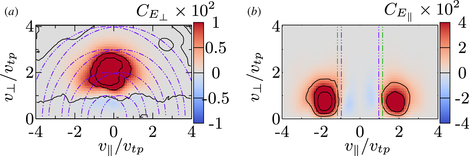
The location in velocity space of the cyclotron energization of the protons generally agrees with predictions for the quasilinear cyclotron diffusion plateau (Kennel & Engelmann Reference Kennel and Engelmann1966; Marsch & Tu Reference Marsch and Tu2001; He et al. Reference He, Wang, Tu, Marsch and Zong2015), where the energy transfer mediated by  $E_{\bot }$ is largest at the confluence of the contours of constant energy for the forward and backward propagating ion-cyclotron waves, which satisfy $\sqrt{(v_{\Vert }\pm \unicode[STIX]{x1D714}/k_{\Vert })^{2}+v_{\bot }^{2}}={\mathcal{C}}$. In figure 4(a), we plot example contours (purple dot-dashed) with ${\mathcal{C}}/v_{tp}=[1,2,3,4]$ for ion-cyclotron waves with $(k_{\Vert }d_{p},k_{\bot }d_{p})=(1,0.2)$, for which the linear Vlasov–Maxwell dispersion relation yields a parallel phase velocity $\unicode[STIX]{x1D714}/k_{\Vert }v_{A}=\unicode[STIX]{x1D714}/k_{\Vert }v_{tp}=0.335$ in this $\unicode[STIX]{x1D6FD}_{p}=1$ plasma.
As shown in figure 2, this simulation generates a broadband turbulent frequency spectrum. The dispersive nature of the Alfvén-ion cyclotron waves leads to a range of parallel phase velocities (and thus a range of frequencies)  $0.13\leqslant \unicode[STIX]{x1D714}/k_{\Vert }v_{A}\leqslant 0.96$ over the range of parallel wavevectors in this simulation, $0.2\leqslant k_{\Vert }\unicode[STIX]{x1D70C}_{p}\leqslant 3.2$. The centres of the sets of circular contours in figure 4(a) would shift with this variation in parallel phase velocities $\unicode[STIX]{x1D714}/k_{\Vert }$, potentially leading to a smearing of the observed velocity-space signature. Therefore, the particular contours (purple) plotted in figure 4(a) for ion-cyclotron waves with $(k_{\Vert }d_{p},k_{\bot }d_{p})=(1,0.2)$ are merely presented as useful guide for the qualitative interpretation of the velocity-space signature.
We also plot in figure 4(b) the parallel field–particle correlation over 2V gyrotropic velocity space,  $C_{E_{\Vert }}(v_{\Vert },v_{\bot })$, given by (4.3), for the same spatial point and using the same correlation interval $\unicode[STIX]{x1D70F}\unicode[STIX]{x1D6FA}_{p}=22.5$ centred at the same time $t\unicode[STIX]{x1D6FA}_{p}=24.66$. Here, we find that protons are energized by the parallel component of the electric field in two regions of velocity space, defined by $1\leqslant |v_{\Vert }/v_{tp}|\leqslant 2.5$ and $0\leqslant v_{\bot }/v_{tp}\leqslant 1.5$.
To interpret quantitatively the location of the parallel energization in velocity space, we plot vertical lines at the resonant parallel phase velocity  $\unicode[STIX]{x1D714}/k_{\Vert }v_{tp}$ for the domain-scale Alfvén waves with $k_{\bot }d_{p}=0.2$ (purple) and for the kinetic Alfvén waves with the peak proton Landau damping rate at $k_{\bot }d_{p}=1.2$(green). We find that the proton energization is negative (blue) for parallel velocities less than the resonant phase velocities $|v_{\Vert }/v_{tp}|<\unicode[STIX]{x1D714}/k_{\Vert }v_{tp}$ and is positive (red) for parallel velocities greater than the resonant phase velocities $|v_{\Vert }/v_{tp}|>\unicode[STIX]{x1D714}/k_{\Vert }v_{tp}$. This typical bipolar signature of the energy transfer about the resonant parallel phase velocity indicates that this collisionless energy transfer is associated with the Landau resonance, consistent with previous determinations of the velocity-space signature of the Landau damping of Alfvén waves in single wave simulations (Howes Reference Howes2017; Klein et al. Reference Klein, Howes and TenBarge2017), gyrokinetic turbulence simulations (Klein et al. Reference Klein, Howes and TenBarge2017) and observations of the Earth’s turbulent magnetosheath (Chen et al. Reference Chen, Klein and Howes2019). The HVM results here represent an independent confirmation of the velocity-space signature of Landau damping in Alfvén-ion cyclotron turbulence.
We further reduce the 2-D gyrotropic velocity space to a function of either  $v_{\bot }$ or $v_{\Vert }$ in figure 5. In this reduced space, we plot the proton distribution function measured at point 40 averaged over the duration of the simulation, as well as the standard deviation around the average value. The structures of $C_{E_{\Vert }}(v_{\Vert })$ and $C_{E_{\bot }}(v_{\bot })$ have the same shape as inferred from the gyrotropic representation. By reducing the correlations to a function of $v_{\bot }$, we can compare the perpendicular heating to quasilinear predictions. If the perpendicular velocity diffusion coefficient associated with cyclotron heating is independent of perpendicular velocity, as predicted by Kennel & Engelmann (Reference Kennel and Engelmann1966) and Isenberg & Vasquez (Reference Isenberg and Vasquez2007), we would expect $C_{E_{\bot }}(v_{\bot })\propto v_{\bot }^{3}\exp (-v_{\bot }^{2}/v_{th}^{2})$. To test this prediction, we fit the average perpendicular thermal width of the reduced proton velocity distribution, $v_{\bot ,tp}^{\text{fit}}$ and then fit $C_{E_{\bot }}(v_{\bot })$ to the functional form $(v_{\bot }/v_{\bot ,tp}^{\text{fit}})^{\unicode[STIX]{x1D6FC}}\exp (-v_{\bot }^{2}/v_{\bot ,tp}^{\text{fit}})^{2}$. We are able to extract a good fit from this procedure but find $\unicode[STIX]{x1D6FC}\approx 6.6$, rather than the expected value of 3, qualitatively similar to the results presented in Arzamasskiy et al. (Reference Arzamasskiy, Kunz, Chandran and Quataert2019), indicating a strong dependence of the energy diffusion on $v_{\bot }$.
Time-averaged reduced proton velocity distributions and their standard deviation measured at a single spatial point (a,b) and the associated reduced correlations  $C_{E_{\bot ,\Vert }}(v_{\Vert })$ (c) and $C_{E_{\bot ,\Vert }}(v_{\bot })$ (d). The vertical dashed lines in (c) indicate the dominant parallel resonant velocities for the simulation, while the black dashed line in (d) represents the best fit to $C_{E_{\bot }}(v_{\bot })$.

It is worth noting that the bipolar aspect of the energy transfer via the Landau resonance is less apparent in this HVM simulation of Alfvén-ion cyclotron turbulence than in previous analyses of gyrokinetic simulations and magnetosheath observations. This smearing out of the velocity-space signature may be due to the perpendicular motions of the large-amplitude Alfvén waves with  $\unicode[STIX]{x1D6FF}B_{\bot }\sim B_{0}$ in the HVM simulation. These relatively large-amplitude Alfvénic fluctuations lead to significant shifts in the proton velocity distribution from the average bulk velocity frame, as seen in the width of the standard deviation about the time-averaged velocity distribution function (VDF) in figure 5(a,b), broadening the velocity-space regions over which energy is transferred. For the anisotropic Alfvénic fluctuations with $k_{\Vert }\ll k_{\bot }$ in gyrokinetic simulations and in the dissipation-range turbulence of the magnetosheath, strong turbulence can be achieved with $\unicode[STIX]{x1D6FF}B_{\bot }\ll B_{0}$, possibly leading to a more clear bipolar velocity-space signature, because the smaller amplitude of the turbulent fluctuations would lead to less smearing of the characteristic bipolar appearance.
The velocity-space signatures of (a) cyclotron damping and (b) Landau damping, computed using single-point measurements of the electric field and proton velocity distribution over the same correlation time interval and at the same position in space, clearly demonstrate a second key result of this study: that the field–particle correlation method can successfully employ single-point measurements to distinguish distinct mechanisms of energy transfer occurring at the same point in space.
Of course, since the parallel correlation  $C_{E_{\Vert }}$ integrated over velocity simply yields $j_{\Vert p}E_{\Vert }$, and the velocity-integrated perpendicular correlation $C_{E_{\bot }}$ yields $\boldsymbol{j}_{\bot p}\boldsymbol{\cdot }\boldsymbol{E}_{\bot }$, one could argue that this separation of cyclotron from Landau energization mechanisms could simply be achieved by separating the parallel and perpendicular components of $\boldsymbol{j}\boldsymbol{\cdot }\boldsymbol{E}$. However, determining the components of $\boldsymbol{j}\boldsymbol{\cdot }\boldsymbol{E}$ provides only the rate of change of spatial energy density due to the different components of $\boldsymbol{E}$, but nothing about the specific physical mechanism responsible for this energy transfer. The field–particle correlations $C_{E_{\Vert }}(\boldsymbol{v},t,\unicode[STIX]{x1D70F})$ and $C_{E_{\bot }}(\boldsymbol{v},t,\unicode[STIX]{x1D70F})$, because they provide the variation of the energization as a function of particle velocity, yield vastly greater detail about the mechanisms through their velocity-space signatures, with the possibility to distinguish one mechanism from another through qualitative or quantitative differences in the characteristic velocity-space signatures of each mechanism.
For example, proton cyclotron damping in a  $\unicode[STIX]{x1D6FD}_{p}=1$ plasma, as shown in figures 4(a) and 5(c,d), is expected to energize protons with velocities $1\leqslant v_{\bot }/v_{tp}\leqslant 3$ and $-1.3\leqslant v_{\Vert }/v_{tp}\leqslant 1.3$. Landau damping in a $\unicode[STIX]{x1D6FD}_{p}=1$ plasma, on the other hand, is expected to energize protons with velocities $1\leqslant |v_{\Vert }/v_{tp}|\leqslant 2.5$ and $0\leqslant v_{\bot }/v_{tp}\leqslant 1.5$, with a bipolar signature changing sign about the parallel resonant phase velocity. These detailed quantitative features enable one to identify the specific physical mechanisms responsible for the energization. Ongoing work to determine the velocity-space signatures of different energization mechanisms, including their variation as a function of the plasma parameters such as $\unicode[STIX]{x1D6FD}_{p}$, will provide a framework for the interpretation of the velocity-space signatures obtained through the field–particle correlation analysis of both kinetic numerical simulations and spacecraft observations, potentially providing a clear procedure for the identification of the particle energization mechanisms that play a role in the dissipation of turbulence in these systems.
5.2 Variation of velocity-space signatures
Now that we have presented fiducial velocity-space signatures for cyclotron damping and Landau damping in figure 4, we seek to quantify the variation of the velocity-space signatures of the 2V gyrotropic perpendicular and parallel correlations  $C_{E_{\bot }}(v_{\Vert },v_{\bot })$ and $C_{E_{\Vert }}(v_{\Vert },v_{\bot })$ in our HVM simulation of Alfvén-ion cyclotron turbulence.
Intuition gained from plane-wave studies of linear collisionless damping of waves often leads people to believe that linear collisionless damping is expected to occur uniformly in space. This belief is not correct. Similar to the case that any spatially varying waveform can be decomposed into its plane-wave components, the spatial distribution of energy transfer associated with linear collisionless damping mechanisms is controlled by the spatial distribution of the field doing the work, and this field may arise in a spatially non-uniform manner if numerous plane-wave modes contribute to the waveform of the field. In plasma turbulence, early studies discovered that intermittent current sheets naturally develop (Matthaeus & Montgomery Reference Matthaeus and Montgomery1980; Meneguzzi, Frisch & Pouquet Reference Meneguzzi, Frisch and Pouquet1981), and more recent work has shown that the dissipation of turbulent energy is largely concentrated near these current sheets (Uritsky et al. Reference Uritsky, Pouquet, Rosenberg, Mininni and Donovan2010; Osman et al. Reference Osman, Matthaeus, Greco and Servidio2011; Zhdankin et al. Reference Zhdankin, Uzdensky, Perez and Boldyrev2013; Navarro et al. Reference Navarro, Teaca, Told, Groselj, Crandall and Jenko2016). Although the idea of dissipation in current sheets suggests a possible role of magnetic reconnection, in fact, a recent study has shown a clear counterexample in which collisionless wave–particle interactions underlie spatially non-uniform energy transfer. In a gyrokinetic simulation where strongly nonlinear Alfvén wave collisions (Howes & Nielson Reference Howes and Nielson2013) self-consistently generate current sheets (Howes Reference Howes2016), spatially non-uniform particle energization occurs, with greater energy transfer near current sheets, but the underlying mechanism of energy transfer in this case is clearly identified, using the field–particle correlation technique, as Landau damping (Howes et al. Reference Howes, McCubbin and Klein2018). Therefore, even if the removal of energy from turbulent fluctuations occurs dominantly through collisionless wave–particle interactions, one would expect that the net energy transfer would vary significantly from point to point in a strongly turbulent system.
Furthermore, collisionless energy transfer via wave–particle interactions is reversible, meaning that in addition to positive energy transfer from the fields to the particles, one can also find regions of negative energy transfer from the particles to the fields. Nonetheless, the regions of negative energy transfer mediated by collisionless wave–particle interactions still yield velocity-space signatures characteristic of the energy transfer mechanism, but with opposite sign (Howes et al. Reference Howes, McCubbin and Klein2018). Here we hope to explore the typical variation in space of the velocity-space signatures of the perpendicular and parallel field–particle correlations, examining regions of positive energy transfer, negative energy transfer, and negligible energy transfer.
Here we characterize the variations of the perpendicular and parallel correlations  $C_{E_{\bot }}(v_{\bot },v_{\Vert })$ and $C_{E_{\Vert }}(v_{\bot },v_{\Vert })$ at four different spatial points in our HVM turbulence simulation, representing cases with significant energy transfer either direction between the protons and $E_{\bot }$ or $E_{\Vert }$, as well as cases with relatively little net energy transfer. To quantify the variation in the velocity-space signature, we use a correlation interval $\unicode[STIX]{x1D70F}\unicode[STIX]{x1D6FA}_{p}=22.5$ to compute the correlation $C_{E_{\bot }}(v_{\bot },v_{\Vert },t,\unicode[STIX]{x1D70F})$ at each point as a function of the time $t$ at the centre of the correlation interval. We compute the mean of this correlation over the entire simulation time $T$,
$T$,  $\langle C_{E_{\bot }}\rangle _{T}$, and the standard deviation of its variation $\unicode[STIX]{x1D70E}(C_{E_{\bot }})$ at each point in gyrotropic velocity space $(v_{\bot },v_{\Vert })$. To visualize the variation in time at each of the four points, we plot in figure 6 the mean value in the central column, the mean minus the standard deviation at each point (a), and the mean plus the standard deviation (c).
Mean secular energy density transfer rate between the protons and  $E_{\bot }$ at four points throughout the HVM simulation, $\langle C_{E_{\bot }}\rangle _{T}$, (b). The velocity-dependent standard deviation at each point is added to or subtracted from the mean in (c) and (a). Contours of constant energy in the wave frame of forward and backward propagating Alfvén-ion cyclotron waves are shown in purple.

Regardless of the sign or amplitude of  $C_{E_{\bot }}$, we see in figure 6 that the transfer associated with $E_{\bot }$ is strongly concentrated between $1\leqslant v_{\bot }/v_{tp}\leqslant 3$ and $-2\leqslant v_{\Vert }/v_{tp}\leqslant 2$. We plot the same contours (purple) of constant $\sqrt{(v_{\Vert }\pm \unicode[STIX]{x1D714}/k_{\Vert })^{2}+v_{\bot }^{2}}={\mathcal{C}}$ for ion-cyclotron waves used in figure 4 with $(k_{\Vert }d_{p},k_{\bot }d_{p})=(1,0.2)$ as a guide for interpretation.
At point 40 in figure 6, where we find significant energy transfer to the protons, we observe that protons with  $v_{\bot }>v_{tp}$ gain a significant amount of energy while protons with $v_{\bot }<v_{tp}$ lose a relatively small amount of energy to $E_{\bot }$. At point 8, where we observe energy transfer from the protons, the pattern remains similar, but with the signs reversed. At points 35 and 11 where the net spatial energy density transfer (integrated over all velocity space) is relatively small, we see two distinct behaviours. At point 35, we find regions of strong energy density transfer of opposite sign in adjacent bands of $v_{\bot }$ that approximately follow contours of constant energy. When integrated over velocity, the opposite signs of these bands significantly reduce the net transfer. At point 11, the sign of $C_{E_{\bot }}$ changes part way through the simulation, leading to little net energy transfer when averaged over the full simulation time.
Mean secular energy density transfer rate between the protons and  $E_{\Vert }$ at the same four points considered in figure 6, $\langle C_{E_{\Vert }}\rangle _{T}$, (b), with the velocity-dependent standard deviation added to or subtracted from the mean in (c) and (a). The Landau resonant velocity for the largest simulated and the most strongly Landau damped Alfvén waves are shown in purple and green.

In figure 7, we present the quantitative analysis of the variation of the parallel correlation  $C_{E_{\Vert }}(v_{\bot },v_{\Vert })$ at the same four points considered in figure 6, with the mean over the entire simulation time $\langle C_{E_{\Vert }}\rangle _{T}$ in (b), and minus or plus the standard deviation in (a,c), respectively. Here we find that the energy transfer is concentrated in two regions, defined by $0.5\leqslant |v_{\Vert }/v_{tp}|\leqslant 3$ and $0\leqslant v_{\bot }/v_{tp}\leqslant 2$.
At all four points, we see some evidence of the bipolar resonant signature associated with Landau damping seen in previous numerical (Howes Reference Howes2017; Klein et al. Reference Klein, Howes and TenBarge2017; Howes et al. Reference Howes, McCubbin and Klein2018) and observational studies (Chen et al. Reference Chen, Klein and Howes2019). The change of sign is generally consistent with the resonant parallel phase velocities of the largest-scale Alfvén waves in the system (purple) and the most strongly damped kinetic Alfvén waves with  $k_{\bot }d_{p}=1.2$ (green). At points 40, 35 and 11, net energy is transferred from $E_{\Vert }$ to the protons, with positive energy transfer at parallel velocities above the resonant velocity and negative energy transfer below. At point 8, where there is net transfer from the protons to $E_{\Vert }$, the bipolar pattern of resonant collisionless energy transfer is the same, but the signs of the energy transfer are reversed, consistent with a previous study of Landau-resonant energization in current sheets generated by strong Alfvén wave collisions Howes et al. (Reference Howes, McCubbin and Klein2018).
The careful reader will note a difference in the widths of the regions of resonant transfer between this simulation and the strong gyrokinetic turbulence simulation described in Klein et al. (Reference Klein, Howes and TenBarge2017). As  $\unicode[STIX]{x1D6FF}B_{\bot }/B_{0}$ is necessarily much larger for this wavevector-isotropic system in order for the simulation to satisfy $\unicode[STIX]{x1D712}=(k_{\bot }/k_{\Vert })(\unicode[STIX]{x1D6FF}B_{\bot }/B_{0})\approx 1$, the proton distribution is more perturbed, resulting in a broadening of the resonant signature. Studies of the effect of variations in $k_{\bot }/k_{\Vert }$ and $\unicode[STIX]{x1D6FF}B_{\bot }/B_{0}$ will be left to future work.
In summary, we find that although the amplitude and sign of the energization of particles by  $E_{\bot }$ and $E_{\Vert }$ varies from position to position in strong turbulence, the regions of velocity space where particles participate in the energy transfer remain remarkably constant. Furthermore, the velocities at which the energy transfer changes sign also appear to be reproducible from point to point. This pattern of energy transfer in velocity space, denoted the velocity-space signature, provides a valuable tool for the identification of the physical mechanisms responsible for the removal of energy from turbulent fluctuations and consequent energization of particles. Further work is needed to determine how these velocity-space signatures change quantitatively as a function of the plasma parameters, in particular the plasma $\unicode[STIX]{x1D6FD}_{p}$, which controls where the wave phase velocities fall within the thermal distribution of particle velocities.
It is worthwhile to note that the different regions in velocity space of energy transfer for  $E_{\Vert }$ and $E_{\bot }$ are partly enforced by the mathematical form of the correlations, equations (4.3) and (4.4). For example, the presence of the $v_{\Vert }^{2}$ term in $C_{E_{\Vert }}$ dictates that the parallel energy transfer must drop to zero as $|v_{\Vert }|\rightarrow 0$, and similarly the presence of the $v_{\bot 1}^{2}$ and $v_{\bot 2}^{2}$ factors in $C_{E_{\bot }}$ require that the perpendicular energy transfer drops to zero as $|v_{\bot }|\rightarrow 0$. Nonetheless, the mathematical forms of $C_{E_{\Vert }}$ and $C_{E_{\bot }}$ are simply the terms for the parallel and perpendicular energy transfer in the equation for the evolution of the phase-space energy density, equation (4.2). Therefore, the results of the correlation can be interpreted directly in physical terms, where the unnormalized correlation is precisely the rate of change of phase-space energy density at each point in 3D–3V phase space. A key additional point to emphasize is that the change of sign of the energy transfer – such as that frequently found at the parallel resonant velocity in $C_{E_{\Vert }}(v_{\Vert },v_{\bot })$ – is not guaranteed by the mathematical form of the correlation. This feature is therefore indicative of the governing physical mechanism, suggesting that such features in the velocity-space signatures of different mechanisms can be used to identify the mechanisms dominating particle energization in both numerical simulations and single-point spacecraft observations.
5.3 Time evolution of  $C_{E_{\bot }}$ and $C_{E_{\Vert }}$


The 2V gyrotropic velocity-space signatures presented in figures 4–7 provide valuable information about the energy transfer as a function of particle velocity but do not contain information about the variation of the energy transfer as a function of time. Time stack plots of the reduced perpendicular correlation  $C_{E_{\bot }}(v_{\bot },t)=\int \text{d}v_{\bot }\,C_{E_{\bot }}(v_{\Vert },v_{\bot },t)$ and reduced parallel correlation $C_{E_{\Vert }}(v_{\Vert },t)=\int \text{d}v_{\Vert }\,C_{E_{\Vert }}(v_{\Vert },v_{\bot },t)$ enable the energy transfer to be visualized as a function of time and the most relevant component of velocity space. The motivation of these particular reductions is the strong dependence of $C_{E_{\bot }}$ on $v_{\bot }$ and weak dependence on $v_{\Vert }$, as seen in figure 6; similarly, $C_{E_{\Vert }}$ has a strong dependence on $v_{\Vert }$ and a weak dependence on $v_{\bot }$, as seen in figure 7. We have therefore not included plots of $C_{E_{\bot }}(v_{\Vert })$ and $C_{E_{\Vert }}(v_{\bot })$.
In figures 8–11, we consider the same four spatial points highlighted earlier in figures 6 and 7. In each figure, columns (a) and (b) present time stack plots of  $C_{E_{\bot }}(v_{\bot },t;\unicode[STIX]{x1D70F}=0)$ and $C_{E_{\bot }}(v_{\bot },t;\unicode[STIX]{x1D70F}\unicode[STIX]{x1D6FA}_{p}=22.5)$. Plotted at the bottom of each column is the mean value averaged over the entire simulation time $T$,
$T$,  $\langle C_{E_{\bot }}(v_{\bot },t,\unicode[STIX]{x1D70F})\rangle _{T}$ (black), with the extent of the standard deviation about the mean (shaded). Columns (c) and (d) present the same for $C_{E_{\Vert }}(v_{\Vert },t;\unicode[STIX]{x1D70F}=0)$ and $C_{E_{\Vert }}(v_{\Vert },t;\unicode[STIX]{x1D70F}\unicode[STIX]{x1D6FA}_{p}=22.5)$. Column (e) presents velocity-integrated energy density transfer rates, $\unicode[STIX]{x2202}_{t}\bar{w}_{E_{\Vert }}$ (black) and $\unicode[STIX]{x2202}_{t}\bar{w}_{E_{\bot }}$ (green) for $\unicode[STIX]{x1D70F}=0$ (dashed) and $\unicode[STIX]{x1D70F}\unicode[STIX]{x1D6FA}_{p}=22.5$ (solid). Note that $\unicode[STIX]{x2202}_{t}\bar{w}_{E_{\Vert }}$ is equal to the work done by the parallel electric field on the protons, $j_{\Vert ,p}E_{\Vert }$, and $\unicode[STIX]{x2202}_{t}\bar{w}_{E_{\bot }}$ is equal to the work done by the perpendicular electric field on the protons, $\boldsymbol{j}_{\bot ,p}\boldsymbol{\cdot }\boldsymbol{E}_{\bot }$.
Reduced field–particle correlations  $C_{E_{\bot }}(v_{\bot })$ with (a) $\unicode[STIX]{x1D70F}=0$ and (b) $\unicode[STIX]{x1D70F}\unicode[STIX]{x1D6FA}_{p}=22.5$ and $C_{E_{\Vert }}(v_{\Vert })$ with (c) $\unicode[STIX]{x1D70F}=0$ and (d) $\unicode[STIX]{x1D70F}\unicode[STIX]{x1D6FA}_{p}=22.5$. The lower panels of columns (a–d) show the time-averaged, velocity-dependent energy transfer rate, with the mean in black and one standard deviation in red. (e) The velocity-integrated spatial energy density transfer rates $\unicode[STIX]{x2202}_{t}\bar{w}_{E_{\bot }}$ (green) and $\unicode[STIX]{x2202}_{t}\bar{w}_{E_{\Vert }}$ (black) are shown for $\unicode[STIX]{x1D70F}\unicode[STIX]{x1D6FA}_{p}=0$ (dashed) and $22.5$ (solid).

Reduced field–particle correlations, organized in the same format at figure 8 but for point 8. At this point, there is a net transfer of energy from the protons to  $E_{\Vert }$ and $E_{\bot }$, with $E_{\Vert }$ receiving more energy.

Reduced field–particle correlations, organized in the same format at figure 8 but for point 35. At this point, there is a net transfer of energy to the protons via  $E_{\Vert }$, and very little transfer of energy mediated by $E_{\bot }$.

Reduced field–particle correlations, organized in the same format at figure 8 but for point 19. At this point, there is relatively little net transfer of energy between the protons and the electric field.

Several key points can be gleaned from the set of time stack plots in figures 8–11. First, in all cases, throughout the evolution of the simulation, the perpendicular energy transfer diagnosed by  $C_{E_{\bot }}(v_{\bot })$ falls primarily in the range $1\leqslant v_{\bot }/v_{tp}\leqslant 3$ and the parallel energy transfer diagnosed by $C_{E_{\Vert }}(v_{\Vert })$ falls primarily within the two ranges $-3\leqslant v_{\Vert }/v_{tp}\leqslant -0.5$ and $0.5\leqslant |v_{\Vert }/v_{tp}|\leqslant 3$, consistent with the findings of the 2V gyrotropic velocity-space signatures in § 5.2. Second, as shown in the lower panels of columns (a,c) in the figures, the instantaneous energy transfer rate (the correlation with $\unicode[STIX]{x1D70F}=0$) experiences a wide variation (shaded region) of $C_{E_{\bot }}(v_{\bot })$ and $C_{E_{\Vert }}(v_{\Vert })$ in time, consistent with the idea of a significant oscillating energy transfer (Howes et al. Reference Howes, Klein and Li2017). This oscillating energy transfer largely averages out over sufficiently long correlation intervals, as shown in the lower panels of columns (b,d) for $\unicode[STIX]{x1D70F}\unicode[STIX]{x1D6FA}_{p}=22.5$, where the variation of the energy transfer rate is greatly diminished, as intended with the field–particle correlation method. This removal of the oscillating component can be seen clearly in the velocity-integrated spatial energy transfer rates $\unicode[STIX]{x2202}_{t}\bar{w}_{E_{\Vert }}$ and $\unicode[STIX]{x2202}_{t}\bar{w}_{E_{\bot }}$ in column (e), where the amplitude of the energy transfer in the instantaneous case ( $\unicode[STIX]{x1D70F}=0$, dashed) is greatly reduced when a sufficiently long correlation interval is chosen ( $\unicode[STIX]{x1D70F}\unicode[STIX]{x1D6FA}_{p}=22.5$, solid).
Third, for the two points, 35 and 11, at which there is little net energy transfer by the perpendicular electric field, we find two different behaviours. Although, as shown in panel (a) both cases display significant instantaneous transfers of energy at various points in velocity and time, the cancellation of these positive and negative transfers is different in the two cases: (i) at point 35, the energy transfer varies as a function of  $v_{\bot }$, so that the velocity-integrated energy transfer remains small at all times; and (ii) at point 11, the velocity-integrated energy transfer is positive at early times and negative at late times, so that, when averaged over time (lower panel, column a), the net energy transfer is small.
Finally, considering all 64 spatial points diagnosed in the simulation (not shown), the fraction of the energy density transfer mediated by  $E_{\Vert }$ compared to the total transfer rate, $|\unicode[STIX]{x2202}_{t}\bar{w}_{E_{\Vert }}|/|\unicode[STIX]{x2202}_{t}\bar{w}_{E_{\Vert }}+\unicode[STIX]{x2202}_{t}\bar{w}_{E_{\bot }}|$, does vary somewhat as a function of spatial location $\boldsymbol{r}_{0}$. The mean and standard deviation of this parallel-to-total energy transfer ratio – averaged over the entire simulation time $T$ and over all 64 diagnosed points $\boldsymbol{r}_{0}$ – is equal to $0.67\pm 0.24$, with no significant variation for different choices of $\unicode[STIX]{x1D70F}$. This result indicates that both $E_{\Vert }$ and $E_{\bot }$ contribute to the energy transfer, though points where one component dominates over the other will be highlighted in the following sections.
6 Comparing electric field and heat flux contributions
As shown by (4.2), the change of phase-space energy density at a given point in 3D–3V phase space  $(\boldsymbol{r},\boldsymbol{v})$ is the sum of changes due to each of the three terms on the right-hand side of the equation. The first term represents the advective heat flux, the second is the work done on the particles by the total electric field (the sum of work done by $E_{\Vert }$ and $E_{\bot }$), and the third is the work done by the magnetic field (which must be zero when integrated over velocity space). The field–particle correlation provides information about the work done by the electric field, but it is worthwhile to analyse how all of the terms lead to the net energy transfer to or from the protons at a single point in space.
To calculate the net rate of change of the spatial energy density at a single point  $\boldsymbol{r}_{0}$ in time, $\unicode[STIX]{x2202}_{t}\bar{w}(\boldsymbol{r}_{0},t)$, we may simply integrate (4.2) over all velocity space, identifying each of the different terms. Note that this equation must be satisfied instantaneously, so we do not time average the correlations in this analysis. The total rate of change in the proton spatial energy density is given by
 $$\begin{eqnarray}\frac{\unicode[STIX]{x2202}\bar{w}}{\unicode[STIX]{x2202}t}(\boldsymbol{r}_{0},t)=\frac{\unicode[STIX]{x2202}}{\unicode[STIX]{x2202}t}\int \text{d}\boldsymbol{v}\,\frac{mv^{2}f}{2}.\end{eqnarray}$$
 The instantaneous rate of work done by the parallel and perpendicular components of the electric field on the protons is simply given by (4.6) with a correlation interval  $\unicode[STIX]{x1D70F}=0$. Note that $\unicode[STIX]{x1D70F}=0$ will be implicitly assumed unless otherwise mentioned for all determinations of $\unicode[STIX]{x2202}_{t}\bar{w}_{E_{\Vert }}(\boldsymbol{r}_{0},t)$ and $\unicode[STIX]{x2202}_{t}\bar{w}_{E_{\bot }}(\boldsymbol{r}_{0},t)$ for the remainder of this section, and the total rate of work done by the electric field is given by $\unicode[STIX]{x2202}_{t}\bar{w}_{E}(\boldsymbol{r}_{0},t)=\unicode[STIX]{x2202}_{t}\bar{w}_{E_{\Vert }}(\boldsymbol{r}_{0},t)+\unicode[STIX]{x2202}_{t}\bar{w}_{E_{\bot }}(\boldsymbol{r}_{0},t)$. Following this procedure, the rate of change of the proton spatial energy density due to the magnetic field is given by
 $$\begin{eqnarray}\unicode[STIX]{x2202}_{t}\bar{w}_{B}(\boldsymbol{r}_{0},t)=\frac{q_{s}}{c}\int \text{d}\boldsymbol{v}\,\frac{v^{2}}{2}(\boldsymbol{v}\times \boldsymbol{B})\boldsymbol{\cdot }\frac{\unicode[STIX]{x2202}f_{s}}{\unicode[STIX]{x2202}\boldsymbol{v}}.\end{eqnarray}$$
 As with the energy transfer rates calculated in § 4, all of the rates in this section are calculated in the time-averaged bulk velocity frame for each spatial point in the simulation. Note that integrating by parts in velocity of (6.2) enables the integrand to be manipulated into the form  $\boldsymbol{v}\boldsymbol{\cdot }(\boldsymbol{v}\times \boldsymbol{B})f_{s}=0$, so the net work done by the magnetic field must equal zero, as expected. Nonetheless, evaluating (6.2) with the numerical velocity derivatives provides a convenient means for estimating the accuracy of the integration and assessment of $\unicode[STIX]{x2202}_{\boldsymbol{v}}f_{s}$.
Since the spatial gradients in the ballistic (advective) term in (4.2) are not available with only single-point measurements, we cannot directly evaluate this term. But, since we can determine all of the other terms in the equation using single-point measurements,Footnote 4 we may obtain the contribution from the advective heat flux at point  $\boldsymbol{r}_{0}$ by combining all of the other terms,
 $$\begin{eqnarray}\unicode[STIX]{x2202}_{t}\bar{w}_{\text{Ball}}(\boldsymbol{r}_{0},t)=\unicode[STIX]{x2202}_{t}\bar{w}-\unicode[STIX]{x2202}_{t}\bar{w}_{E}(\boldsymbol{r}_{0},t)-\unicode[STIX]{x2202}_{t}\bar{w}_{B}(\boldsymbol{r}_{0},t).\end{eqnarray}$$
(a–d) Components of the energy density transfer rate  $\unicode[STIX]{x2202}_{t}\bar{w}$ due to the electric field (blue), magnetic field (green), and the ballistic term (red), as well as the overall transfer rate (black) at four points in the simulation domain. (e) The mean and standard deviation of the ballistic and instantaneous (correlation length $\unicode[STIX]{x1D70F}=0$) electric field transfer rates at each spatial point. (f) The mean and standard deviation of the transfer rate due to the perpendicular and parallel electric field, with correlation length $\unicode[STIX]{x1D70F}\unicode[STIX]{x1D6FA}_{p}=22.5$.

In figure 12, we plot the time evolution of the contributions to the rate of change in the proton spatial energy density at spatial points (a) 40, (b) 8, (c) 35 and (d) 11: (i) total change in proton spatial energy density  $\unicode[STIX]{x2202}_{t}\bar{w}(\boldsymbol{r}_{0},t)$ (black); (ii) the ballistic (heat flux) contribution $\unicode[STIX]{x2202}_{t}\bar{w}_{\text{Ball}}(\boldsymbol{r}_{0},t)$, (red); (iii) the total electric-field contribution $\unicode[STIX]{x2202}_{t}\bar{w}_{E}(\boldsymbol{r}_{0},t)$ (blue); and (iv) the magnetic field contribution $\unicode[STIX]{x2202}_{t}\bar{w}_{B}(\boldsymbol{r}_{0},t)$ (green). As expected the contribution from the magnetic field is nearly zero, providing a practical diagnostic for the accuracy of our velocity derivatives of the 3V distribution function at a given point, $f_{p}(\boldsymbol{r}_{0},\boldsymbol{v},t)$.
A salient, and somewhat unexpected, feature that stands out in the time series in panels (a–d) is the strong anti-correlation of the ballistic (red) and electric-field (blue) terms. This anti-correlation can be quantified by plotting the mean value, over the entire simulation duration  $T$, of the energy transfer due to these two terms, $\langle \unicode[STIX]{x2202}_{t}\bar{w}_{\text{Ball}}\rangle _{T}$ and $\langle \unicode[STIX]{x2202}_{t}\bar{w}_{E}\rangle _{T}$ against each other for each of the 64 spatial points, as shown in figure 12(e) with error bars given by the standard deviations of the means. While the standard deviation of these energy transfer rates has a significant spread, the mean values are well described with a linear fit of $\unicode[STIX]{x2202}_{t}\bar{w}_{\text{Ball}}=-1.005\unicode[STIX]{x2202}_{t}\bar{w}_{E}+0.004$, a nearly perfect anti-correlation.
One plausible interpretation of this finding is that, when energy is transferred to the protons by the electric field, the heat flux efficiently advects the energy away. Conversely, when energy is lost from the protons through energy transfer to the electric field, the heat flux causes a net energy flow to that point in space. In other words, energy is efficiently transported away from regions where  $\boldsymbol{j}\boldsymbol{\cdot }\boldsymbol{E}$ is positive, and toward regions where $\boldsymbol{j}\boldsymbol{\cdot }\boldsymbol{E}$ is negative. The anti-correlation between $\unicode[STIX]{x2202}_{t}\bar{w}_{E}$ and $\unicode[STIX]{x2202}_{t}\bar{w}_{\text{Ball}}$ supports the general picture of two different recent energy transport models, described in Yang et al. (Reference Yang, Matthaeus, Parashar, Haggerty, Roytershteyn, Daughton, Wan, Shi and Chen2017) and Howes et al. (Reference Howes, McCubbin and Klein2018), where the electromagnetic work done on the particles is merely one step in a process of converting turbulent energy into plasma heat. It must be emphasized that, although locally the field–particle and advective terms nearly cancel out, only the field–particle term represents a net (integrated over configuration space volume) change in the particle energy, and thus represents particle energization. The ballistic term simply leads to a transport in configuration space of the energy gained by the particles when $\boldsymbol{E}$ does work.
The anti-correlation identified in figure 12(e) does not establish cause and effect: is the change in spatial energy density driven by the work done by the electric field or by the heat flux? A detailed look at the time evolution of the heat flux and electric field terms over the time range  $0\leqslant t\unicode[STIX]{x1D6FA}_{p}\leqslant 8$ in figure 12(a) suggests that the work by the electric field is the primary driver of the energy evolution. Over the interval $0\leqslant t\unicode[STIX]{x1D6FA}_{p}\leqslant 3$, the electric field is energizing the protons (blue), and the rate of change of the spatial energy density is positive (black). At $t\unicode[STIX]{x1D6FA}_{p}=3$, the rate of work done by the electric fields peaks and then begins to decline; at the same time, the rate of change spatial energy density swings to negative (black), suggesting that the removal of energy density by the heat flux (red) begins to dominate, advecting energy away from the diagnosed point. This evolution suggests that first the electric field energizes the protons locally, and subsequently the extra energy is carried away by advection.
Finally, in figure 12(f), we plot the time-averaged rate of work done by the parallel electric field  $\langle \unicode[STIX]{x2202}_{t}\bar{w}_{E_{\Vert }}(\boldsymbol{r}_{0},t,\unicode[STIX]{x1D70F}\unicode[STIX]{x1D6FA}_{p}=22.5)\rangle _{T}$ and perpendicular electric field $\langle \unicode[STIX]{x2202}_{t}\bar{w}_{E_{\bot }}(\boldsymbol{r}_{0},t,\unicode[STIX]{x1D70F}\unicode[STIX]{x1D6FA}_{p}=22.5)\rangle _{T}$ against one another, with error bars from the standard deviations. We find that the statistical correlation between parallel and perpendicular energization is fairly weak, with a mean and standard deviation of $0.15\pm 0.53$, indicating that the energy transfer due to $E_{\Vert }$ and $E_{\bot }$ are not strongly correlated.
In summary, the unexpectedly clear anti-correlation found here between the heat flux and electric-field terms motivates a more detailed investigation of their time evolution, with an aim to identify cause and effect, rather than just anti-correlation. Consideration of the contribution of the heat flux to the rate of change of the spatial energy density, especially in systems with significant spatial inhomogeneities, will be essential for fully characterizing the entire chain of energy transport from turbulent plasma flows and electromagnetic fields to plasma heat.
7 Conclusions
We present in this work the first application of the field–particle correlation technique to a system of Alfvén -ion cyclotron turbulence, using electromagnetic field and proton distribution data drawn from an HVM numerical simulation of kinetic protons and fluid electrons. Unlike previous tests of the field–particle correlation technique using gyrokinetic simulations of strong plasma turbulence that prohibit the possibility of ion-cyclotron damping (Klein et al. Reference Klein, Howes and TenBarge2017), the use of a hybrid code enables collisionless energy transfer to the protons via both the Landau and cyclotron resonances. An isotropic simulation domain over a range of wavevectors spanning ion kinetic scale lengths was chosen here to allow proton energization by both Landau damping and cyclotron damping. This simulation domain is not necessarily representative of solar wind turbulence, which is typically found to have more significant wavevector anisotropies.
The first key finding of this study is that we have provided the first numerical determination of the characteristic velocity-space signature of proton cyclotron damping in a strong turbulence simulation using the field–particle correlation technique, shown in figure 4(a). The region of velocity space controlling the energy transfer –  $1\leqslant v_{\bot }/v_{tp}\leqslant 3$ and $-2\leqslant v_{\Vert }/v_{tp}\leqslant 2$ – is largely consistent with the formation of a cyclotron diffusion plateau, of the kind observed in in situ solar wind measurements, e.g. He et al. (Reference He, Wang, Tu, Marsch and Zong2015). The velocity region of energization is inconsistent with the predictions of stochastic heating by low-frequency Alfvénic turbulence (Chandran et al. Reference Chandran, Li, Rogers, Quataert and Germaschewski2010), which is predicted to preferentially heat particles with $v_{\bot }/v_{tp}\lesssim 1$ (Klein & Chandran Reference Klein and Chandran2016).
Our study also confirmed the characteristic bipolar velocity-space signature of Landau damping with an independent numerical code, confirming previous determinations in single kinetic Alfvén wave simulations (Howes Reference Howes2017; Klein et al. Reference Klein, Howes and TenBarge2017), gyrokinetic simulations of strong plasma turbulence (Klein et al. Reference Klein, Howes and TenBarge2017) and observations of the Earth’s turbulent magnetosheath (Chen et al. Reference Chen, Klein and Howes2019). The determination of the velocity-space signatures of both cyclotron damping and Landau damping acting simultaneously at the same point clearly demonstrates a second key result: the field–particle correlation method can successfully employ single-point measurements to distinguish distinct mechanisms of energy transfer occurring at the same point in space. Note that, although a simple decomposition of the components of  $\boldsymbol{j}\boldsymbol{\cdot }\boldsymbol{E}$ can separate the perpendicular and parallel contributions, the velocity-space signatures generated by the field–particle correlation technique provide a practical means to identify definitively the physical mechanisms that are responsible, even when multiple channels of energization are occurring simultaneously.
This study also quantitatively characterized the variations of the velocity-space signatures of proton cyclotron damping and Landau damping at different points in space and time, finding that the pattern of energy transfer in velocity space generally persists, although the signs of the energy transfer can switch since collisionless wave–particle interactions are reversible, sometimes leading to energy transfer from the particles to the electric field.
An unexpected finding here is a strong anti-correlation of the rate of change of spatial energy density at a single point between the ballistic (advective heat flux) and electric-field terms. Preliminary indications suggest that, first, the electric field energizes the protons locally, and subsequently the extra energy is carried away by advection, but a more detailed investigation of the time evolution of these physical mechanisms that change the local spatial energy density is required to confirm this hypothesis.
Further work is needed to explore the variation of the velocity-space signatures of different particle energization mechanisms with changes in the plasma parameters (e.g.  $\unicode[STIX]{x1D6FD}_{p}$ and $T_{p}/T_{e}$) and the characteristics of the turbulence (e.g. nonlinear parameter $\unicode[STIX]{x1D712}$ and anisotropy of turbulence in wavevector space). Ultimately, we aim to develop a framework of characteristic velocity-space signatures of different proposed particle energization mechanisms using the field–particle correlation technique, which unlike other methods for studying plasma heating and particle energization that require measurements of spatial gradients (e.g. Yang et al. (Reference Yang, Matthaeus, Parashar, Haggerty, Roytershteyn, Daughton, Wan, Shi and Chen2017)) is designed to be implemented using only single-point measurements. This framework can then be used to interpret the results of the field–particle correlation analysis of single-point particle velocity distribution and electromagnetic field measurements from current and future spacecraft missions, such as Magnetospheric MultiScale and Parker Solar Probe. The ultimate goal is to identify the dominant mechanisms of particle energization and compute the resulting rates of particle energization due to the damping of turbulence in key regions of the heliosphere – the solar corona, solar wind and planetary magnetospheres.
Acknowledgements
The authors would like to thank C. Chen, J. Kasper, M. Kunz and L. Arzamasskiy for helpful discussions during the execution of this project. K.G.K. was supported by NASA grants 80NSSC19K1390 and 80NSSC19K0912. J.M.T. was supported by NSF SHINE award AGS-1622306, and G.G.H. was supported by NASA grants HSR 80NSSC18K1217, HGI 80NSSC18K0643, and MMSGI 80NSSC18K1371. F.V. has been partially supported by the Agenzia Spaziale Italiana under the contract no. ASI-INAF 2015-0390R.O Numerical simulations have been performed on the supercomputer MARCONI at CINECA, Italy.
Editor Alex Schekochihin thanks the referees for their advice in evaluating this article.
Appendix A. Single-point mode identification
In this paper, we present the velocity-space signature of ion-cyclotron damping using the field–particle correlation technique, illustrated in figure 4(a). To establish that this is indeed due to the ion-cyclotron resonance, we show here that the simulation of turbulence indeed contains ion-cyclotron waves that are expected to damp collisionlessly via the ion-cyclotron resonance.
A common method to diagnose the nature of simulated turbulence is to calculate power as a function of both frequency and length scale, and compare the result to linear predictions, producing so-called  $\unicode[STIX]{x1D714}-k$ diagrams. Such diagrams are not necessarily a reliable way to identify wave modes in strong plasma turbulence. For example, in figure 5 of TenBarge & Howes (Reference TenBarge and Howes2012), a plot of $\unicode[STIX]{x1D714}$ versus $k_{\bot }$ for strong kinetic Alfvén (KAW) turbulence shows significant broadening, which is interpreted to be due to the strong nonlinear energy transfer among modes, and is not directly comparable to the typical linear $\unicode[STIX]{x1D714}(\boldsymbol{k})$ dispersion relations.
To identify the nature of the turbulence simulated in this work using the single-point time series presented in the main text, we consider the relations among different components of the turbulent fluctuations and compare to the predicted eigenfunctions for different wave modes from linear kinetic theory. The practice of calculating these relations, including various helicities, polarizations and other transport ratios (Gary Reference Gary1986; Gary & Winske Reference Gary and Winske1992; Gary Reference Gary1993; Krauss-Varban, Omidi & Quest Reference Krauss-Varban, Omidi and Quest1994; Song, Russell & Gary Reference Song, Russell and Gary1994), has a long history of application to in situ observations of both the magnetosphere (Denton et al. Reference Denton, Gary, Li, Anderson, Labelle and Lessard1995; Lacombe & Belmont Reference Lacombe and Belmont1995; Schwartz, Burgess & Moses Reference Schwartz, Burgess and Moses1996; Zhu et al. Reference Zhu, He, Verscharen and Zhao2019) and solar wind (He et al. Reference He, Marsch, Tu, Yao and Tian2011; Salem et al. Reference Salem, Howes, Sundkvist, Bale, Chaston, Chen and Mozer2012; TenBarge et al. Reference TenBarge, Podesta, Klein and Howes2012; Chen et al. Reference Chen, Boldyrev, Xia and Perez2013; Roberts, Li & Li Reference Roberts, Li and Li2013; Klein et al. Reference Klein, Howes, TenBarge and Podesta2014; Verscharen, Chen & Wicks Reference Verscharen, Chen and Wicks2017; Wu et al. Reference Wu, Verscharen, Wicks, Chen, He and Nicolaou2019); see Klein (Reference Klein2013) for a more exhaustive review.
(a,b) Normalized frequency  $\unicode[STIX]{x1D714}(\boldsymbol{k}\unicode[STIX]{x1D70C}_{p})/\unicode[STIX]{x1D6FA}_{p}$, (c,d) electric-field polarization $\text{Pol}_{E_{xy}}(\boldsymbol{k}\unicode[STIX]{x1D70C}_{p})$, equation (A 1) and (e,f) density–magnetic-field correlation $\langle \unicode[STIX]{x1D6FF}n,\unicode[STIX]{x1D6FF}B_{\Vert }\rangle (\boldsymbol{k}\unicode[STIX]{x1D70C}_{p})$, equation (A 2), for the Alfvén and fast dispersion surfaces over wavevectors simulated in this work. The grey lines indicate parallel, oblique and perpendicular cuts used for comparison to frequency series in figure 14.

Two particularly useful measures to distinguish between the normal modes accessible to the region of wavevector space simulated in this work, namely ion-cyclotron (ICW) and KAW waves on the Alfvén dispersion surface, and whistlers on the fast dispersion surface, are the circular polarization of the electric field about the magnetic field,
 $$\begin{eqnarray}\text{Pol}_{E_{xy}}=\frac{i(E_{x}E_{y}^{\ast }-E_{x}^{\ast }E_{y})}{|E_{x}||E_{y}|}\end{eqnarray}$$
and the density–magnetic-field correlation (Howes et al. Reference Howes, Bale, Klein, Chen, Salem and TenBarge2012; Klein et al. Reference Klein, Howes, TenBarge, Bale, Chen and Salem2012),
 $$\begin{eqnarray}\langle \unicode[STIX]{x1D6FF}n,\unicode[STIX]{x1D6FF}B_{\Vert }\rangle =\frac{\left(\unicode[STIX]{x1D6FF}n^{\ast }\unicode[STIX]{x1D6FF}B_{\Vert }+\unicode[STIX]{x1D6FF}n\unicode[STIX]{x1D6FF}B_{\Vert }^{\ast }\right)}{|\unicode[STIX]{x1D6FF}n|\,|\unicode[STIX]{x1D6FF}B_{\Vert }|},\end{eqnarray}$$
 where  $\unicode[STIX]{x1D6FF}\boldsymbol{E}$, $\unicode[STIX]{x1D6FF}\boldsymbol{B}$ and $\unicode[STIX]{x1D6FF}n$ are complex-valued Fourier coefficients. These two eigenfunction relations, along with the normal mode frequencies $\unicode[STIX]{x1D714}/\unicode[STIX]{x1D6FA}_{p}$, for the Alfvén and fast dispersion surfaces are plotted in figure 13.
The electric-field polarization changes sign between the parallel and perpendicular kinetic extensions of the Alfvén solution, from left-handed ICWs to right-handed KAWs. The fast modes are nearly uniformly right-handed over this wavevector regime. Density and magnetic-field fluctuations are strongly anti-correlated for oblique Alfvén solutions, weakly correlated for parallel Alfvén solutions, and strongly correlated for all fast mode solutions.
Electric-field polarization, equation (A 1), and density–magnetic-field correlation, equation (A 2), calculated from frequency spectra drawn from the four spatial points investigated in this work. Expectations from linear theory along the grey arrows in figure 13 for both the Alfvén and fast dispersion surfaces are indicated with dashed lines.

These two eigenfunction relations can be used to identify the presence of ICWs in our turbulent simulation using only single-point time series of measurements, similar to what is measurable with spacecraft missions. At each of the four spatial points examined in the main text, we Fourier transform in time to obtain the complex Fourier coefficients (as a function of frequency) for  $E_{x}$, $E_{y}$, $\unicode[STIX]{x1D6FF}n$ and $\unicode[STIX]{x1D6FF}B_{\Vert }$. From these complex Fourier coefficients, we compute the circular polarization using (A 1) and the density–magnetic-field correlation using (A 2) as a function of normalized angular frequency $\unicode[STIX]{x1D714}/\unicode[STIX]{x1D6FA}_{p}$ (solid lines in figure 14).
To compare to the predicted variation of these eigenfunction relations for the waves from linear kinetic theory, we compute the values  $\text{Pol}_{E_{xy}}$ and $\langle \unicode[STIX]{x1D6FF}n,\unicode[STIX]{x1D6FF}B_{\Vert }\rangle$ along particular trajectories through $(k_{\bot },k_{\Vert })$ wavevector space, indicated in figure 13 by the grey arrows.Footnote 5 For example, the ‘parallel’ path (vertical grey arrow) transitions from the regime of Alfvén waves to the regime of ICWs, whereas the ‘perpendicular’ path (horizontal grey arrow) transitions from the regime of Alfvén waves to the regime of KAWs. These predicted theoretical values are plotted in figure 14 as dashed lines.
Examining first  $\text{Pol}_{E_{xy}}$ in figure 14, at the lowest frequencies $\unicode[STIX]{x1D714}/\unicode[STIX]{x1D6FA}_{p}\leqslant 0.4$ (which correspond only to the Alfvén solutions, as all of the fast wave modes have higher frequencies $\unicode[STIX]{x1D714}/\unicode[STIX]{x1D6FA}_{p}\geqslant 0.4$), we find $\text{Pol}_{E_{xy}}<0$ for three of the four spatial points. The only region for the Alfvén or fast solutions that has $\text{Pol}_{E_{xy}}<0$ is the ICW regime, so we can conclude that, at those three points, there exists a significant contribution of ICW fluctuations. At $\unicode[STIX]{x1D714}/\unicode[STIX]{x1D6FA}_{p}>0.4$, we find $\text{Pol}_{E_{xy}}\geqslant 0$ at all four points, suggesting that the fluctuations at these frequencies are either KAWs or any of the fast mode fluctuations.
Turning next to  $\langle \unicode[STIX]{x1D6FF}n,\unicode[STIX]{x1D6FF}B_{\Vert }\rangle$ in figure 14, again at the lowest frequencies $\unicode[STIX]{x1D714}/\unicode[STIX]{x1D6FA}_{p}\leqslant 0.4$ we find a $\langle \unicode[STIX]{x1D6FF}n,\unicode[STIX]{x1D6FF}B_{\Vert }\rangle >0$, agreeing well with the prediction for ICWs (light blue, dashed line). Shifting to the frequency range $0.4\leqslant \unicode[STIX]{x1D714}/\unicode[STIX]{x1D6FA}_{p}\leqslant 0.9$, we find $\langle \unicode[STIX]{x1D6FF}n,\unicode[STIX]{x1D6FF}B_{\Vert }\rangle <0$ for three of the four spatial points. Since only the KAW regime has $\langle \unicode[STIX]{x1D6FF}n,\unicode[STIX]{x1D6FF}B_{\Vert }\rangle <0$, we conclude that a substantial fraction of the fluctuations in this frequency range are KAWs.
In conclusion, at the lowest frequencies  $\unicode[STIX]{x1D714}/\unicode[STIX]{x1D6FA}_{p}\leqslant 0.4$, the combination of $\text{Pol}_{E_{xy}}<0$ and $\langle \unicode[STIX]{x1D6FF}n,\unicode[STIX]{x1D6FF}B_{\Vert }\rangle >0$ provides strong evidence that we indeed observe ICWs in our turbulence simulation. Furthermore, looking at magnetic and electric frequency power spectra in figure 2, there is significant power at these low frequencies, so we expect that ion-cyclotron damping may indeed play a key role in the removal of energy from the turbulent fluctuations in the simulation. In addition, in the frequency range $0.4\leqslant \unicode[STIX]{x1D714}/\unicode[STIX]{x1D6FA}_{p}\leqslant 0.9$, the combination of $\text{Pol}_{E_{xy}}>0$ and $\langle \unicode[STIX]{x1D6FF}n,\unicode[STIX]{x1D6FF}B_{\Vert }\rangle <0$ provides strong evidence for the presence of KAWs in the turbulence simulation. Therefore, we may expect to see signatures of ion Landau damping in our simulation.


