


Introduction
With the rapid advance of science and technology including satellite communication, mobile satellite communications that work at high frequencies such as Ku-band have been further studied [Reference Bayer, Krauss, Zaiczek, Stephan, Enge-Rosenblatt and Hein1–Reference Pearson3]. In order to meet the application requirements of high-speed moving objects such as vehicles and airplanes, the antenna must have a low profile and aerodynamic shape. A typical parabolic antenna has the characteristics of high gain and low cross-polarization [Reference Wan, Lu, Wang and Ai4, Reference Washington, Yoon, Angelino and Theunissen5]. Meanwhile, the volume of parabolic antenna keeps extremely bulky. The phased array antenna, which has fast electronic beam scanning capability and a low profile, usually cost too much due to a large number of expensive T/R components [Reference Sandhu, Arnieri, Amendola, Boccia, Meniconi and Ziegler6, Reference Han, Du, Wu and Yang7].
Variable inclination continuous transverse stub (VICTS) antenna is a novel antenna evolved from continuous transverse stub (CTS) antenna [Reference Milroy, Coppedge and Lemons8–Reference Foglia Manzillo, Ettorre, Casaletti, Capet and Sauleau12]. It has the same low profile, high gain, and wide bandwidth as the CTS antenna. At the same time, the beam scanning capability has been significantly improved, which can be widely applied in various situations [Reference Tekkouk, Hirokawa, Sauleau and Ando13, Reference Lou, Yang, Qiu, Yin and Gao14]. The VICTS antenna consists of a radiation plate and a feeding plate placed in parallel, as shown in Fig. 1. The beam scanning can be realized by rotating the two plate of the VICTS antenna relatively, and the beam direction of the radiation pattern can be quickly calculated according to the relative rotation angle [Reference Gao, Lei, Wu and Li15]. VICTS antenna is a very popular solution for mobile satellite communication due to its simple structure, easy processing, and low cost.
Main structure diagram of VICTS antenna.

In previous work, some methods of suppressing the sidelobe level (SLL) have been applied to the CTS antenna. The ridge waveguide slot array (RWSA) is adopted as a linear source to feed the CTS array [Reference Lu, Gu, Wang, Liu and Lu16]. The RWSA was built to obtain low SLL of − 25 dB by controlling the size and position of the slots. In [Reference You, Lu, Wang, Yang, Hao, You and Huang17], an antenna is composed of a 45° linear polarizer and 32-slots fed by a 1-to-256 power divider. The E-plane and H-plane of the antenna are rotated to positions that are 45° away from the two principal axes of the pattern. The SLL in E-plane is reduced to − 28 dB. The SLL in E-plane of the CTS array fed by nonuniform corporate feed network can be suppressed to − 28 dB by employing the Gaussian distribution of the slots [Reference Potelon, Ettorre and Sauleau18]. In [Reference Porter19], the researchers propose a closed-form expression for VICTS antenna patterns with the same excitation amplitude for each element. Such an amplitude distribution cannot be realized in practice. But the mathematical model in this paper is based on the physical parameters of VICTS antenna and can be used in the actual antenna design.
As far as the author's knowledge and all open literature are concerned, there is no low SLL optimization method for VICTS antenna yet. Inevitably, the SLL deteriorates to − 13.5 dB. This paper presents a calculation method for the pattern of VICTS antenna at different scanning angles. This method can be used to optimize the SLL of VICTS antenna. High consistency is obtained by comparing the results of theoretical calculation and full-wave simulation.
Theoretical model of VICTS antenna
This section gives the main structure and the principles of the VICTS antenna. As shown in Fig. 2, the radiation plate is composed of several slot in series, which match the active impedance of the array through a single matching section [Reference Potelon, Ettorre, Coq, Bateman, Francey, Lelaidier, Seguenot and Sauleau20]. In order to make the aperture field distribution relatively uniform, two types of radiation slots with the same period d and different widths w 1 and w 2 are selected.
Partial side view of VICTS antenna.

The radiation efficiency of the slot is controlled by multiple parameters, which can be calculated by the full-wave simulation software CST [Reference Hao, Cheng and Wu9]. The radiation efficiency of the slot increases as the height h decreases, and as the width w i(i = 1, 2) increases. When w i and h are determined, the radiation efficiency of the slot is also determined and recorded as η0i(i = 1, 2).
In addition, the radiation efficiency of the slot is related to the operating frequency of the antenna. It is necessary to obtain the radiation capability of the slot through full-wave simulation while scaling to a different frequency.
Mathematical model of radiation pattern of VICTS
The theoretical model of the VICTS antenna is shown in Fig. 3 when there is no relative rotation between the radiation plate and feeding plate. Although the radiation plate keeps circular, the energy is mainly distributed in the rectangle which is slightly wider than the width of the parallel plate waveguide. Therefore, only the contribution in the rectangular region is considered in order to simplify the analysis. The length L x and width L y of the rectangle correspond to the narrow beamwidth axis and the wide beamwidth axis of the radiation pattern, respectively.
Schematic diagram of the equivalent array of VICTS when the plate is not rotating.

In the main radiation region, the number of narrow slots is N 1. The number of wide slots is N 2, thus

Since each slot is parallel to the feed port, the electric field at different positions of the same slot does not change with the change of the Y coordinate. ${ {\dot I}}_{n}$ can be expressed as follows:

where k = 2πf/c, f is the operating frequency, c is the speed of light in vacuum, ɛ e is the equivalent dielectric constant of the slow-wave structure [Reference Verbitskii21, Reference You, Lu, You, Wang, Huang and Lancaster22], I n is the unit amplitude, which can be expressed as

In this case, one-dimensional linear array theory can be used to calculate the antenna's radiation pattern F(θ, φ).

where C is the cell pattern.
As shown in Fig. 4, when the two plates of the VICTS antenna rotate relatively, the angle between the radiation slot and the equal phase plane is denoted as γ. The amplitude and phase of different positions on the same slot are no longer the same, so the radiation pattern cannot be simply calculated as before.
Schematic diagram of the equivalent array of VICTS antenna when the plate rotates γ.
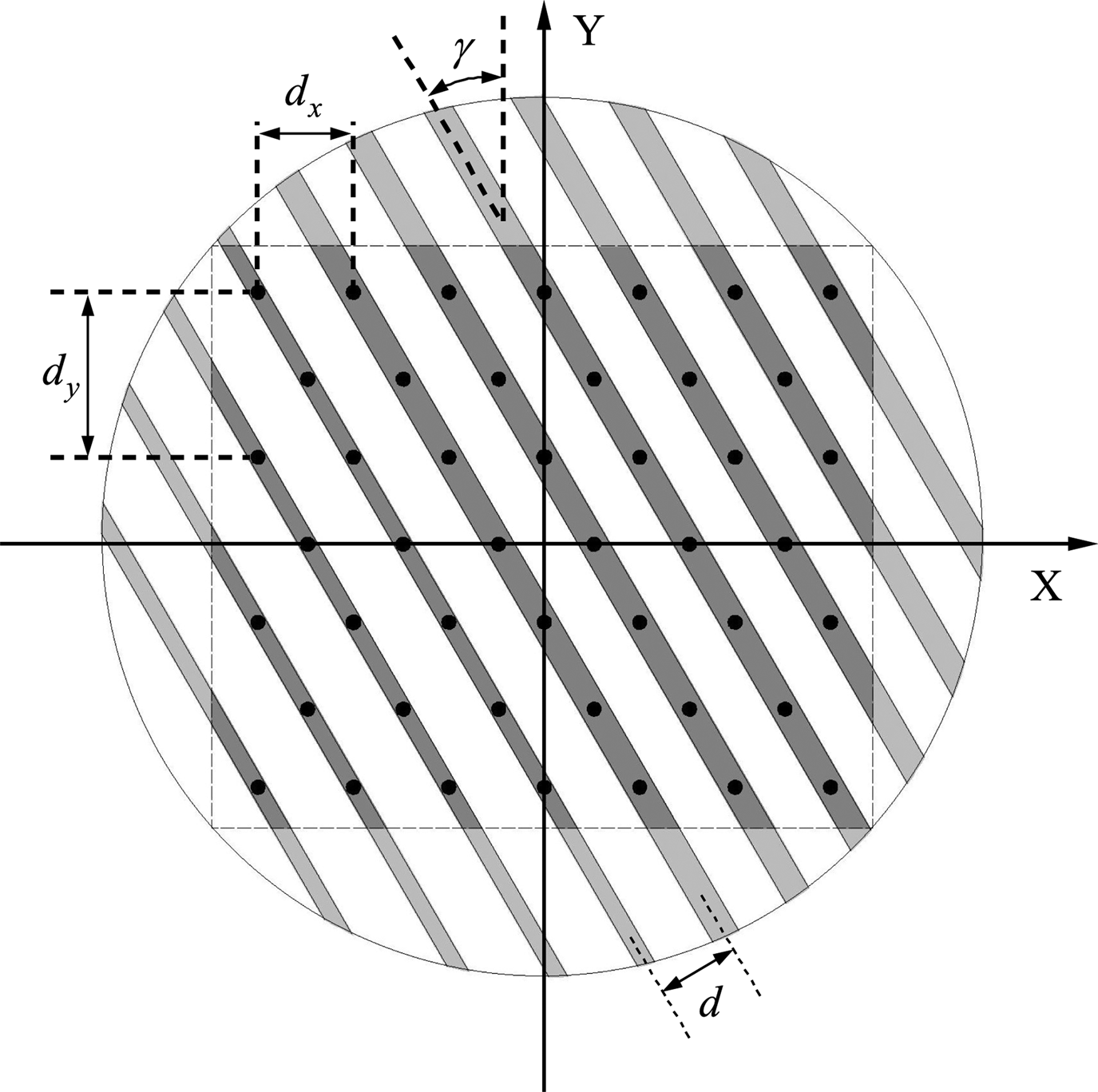
The VICTS antenna is regarded as a two-dimensional array by dispersing the different positions on the radiation slot at equal distance. The element spacing in X-axis direction and Y-axis direction is d x and d y, respectively [Reference Porter19].

There are $M = a\lfloor {L_y}/{d_y}\rfloor$ rows in the Y-axis direction where a is a coefficient. The larger a is, the more points there are, and the more accurate the calculation results are, but the larger the amount of calculation is. a should be increased to ensure the accuracy when the rotation angle γ is larger. $\lfloor \bullet \rfloor$
 is a down rounding function.
The number of elements in each row in X-axis direction is $N = \lfloor {L_x}/{d_x}\rfloor$ , of which the small radiation capacity is N 0. Therefore, with the decrease of the Y coordinate, the number of narrow slots is N 0 increases step by step.

The coordinates of each element can be expressed as follows:

When the radiation plate and the feeding plate rotate relatively, the electric field of each point is different because the radiation plate is composed of a variety of branches with different radiation efficiency. After determining the position of each element and the number distribution of slots parallel to the X-axis, the electric field of each element can be expressed as:

Therefore, the pattern of the antenna can be expressed as:

The antenna pattern is converted to U − V coordinate by the following transformation:

The short axis pattern of the antenna can be obtained by taking the section parallel to the U-axis and passing through the maximum value of the pattern.
Result analysis
In this section, the VICTS antenna with a radius of 350 mm working in 13.75–14.5 GHz band is used. Fig. 5(a) shows the simulation result of aperture field distribution of CST model, and Fig. 5(b) shows the aperture field distribution calculated by MATLAB. Because energy diffusion and energy reflection are not considered in the theoretical calculation model, the results of aperture field distribution of the theoretical calculation model are different from those of CST simulation model. However, the electric field along the X-axis has the same downward trend, so the theoretical calculation model can be used to estimate the SLL.
Aperture field distribution of VICTS. (a) Results of full wave simulation, (b) Results of mathematical model calculation.

The simulation pattern and theoretical calculation pattern of the VICTS antenna in the short axis plane of 0° and 30° are shown in Fig. 6(a) when h is 6 mm. At different rotation angles, the waveforms of the two patterns are consistent. The position of sidelobe is calculated accurately, and the SLL error is less than 1 dB. Part of the reason for the SLL error is that the equivalent magnetic current is used as the antenna subarray to simplify the calculation. As shown in Fig. 6(b), when h is 5 mm, the SLL error is still consistent with Fig. 6(a). Therefore, it is feasible to replace subarray with equivalent magnetic current.
Schematic diagram of the equivalent array of VICTS antenna when the plate rotates γ. (a) h = 6 mm (b) h = 5 mm.

In order to verify that the model can be used in the case of more than two groups of different radiation branches, the simulation results and theoretical calculation results of the antenna model with three groups of radiation branches are given in Fig. 7. The patterns obtained by the two methods are still highly consistent. This model can be used to calculate the pattern of VICTS antenna with any group of different radiation branches.
Radiation pattern of VICTS antenna with three radiation branches.
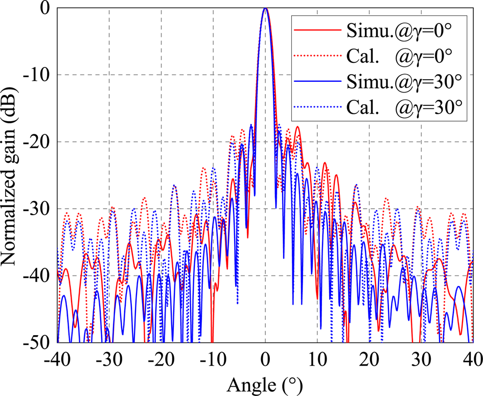
Fig. 8(a) shows the SLL error at different angles. The plate rotation angle is from 0° to 50° and the pitch angle is from 5° to 70°, respectively. As can be seen from the figure, with the change of rotation angle γ, the SLL calculated by mathematical model and simulation results show the same variation trend, and the SLL error always remains below 1.2 dB under different rotation angles. When the antenna operates at different frequencies, the error between simulation and calculation remains at a low level (Fig. 8(b)). Therefore, the mathematical model can be used to calculate the SLL of the VICTS antenna and perform low sidelobe design.
SLL error in various cases. (a) f = 14.25 GHz (b) γ = 0°.

Based on the mathematical model, the low sidelobe design of VICTS antenna is carried out by combining multiple radiation branches and nonlinear slow wave structure. The number of radiation branches and the height of slow wave structure at different positions are taken as optimization parameters. During the optimization process, the aperture field of the antenna evolved in a tapered distribution, so the SLL was reduced. The radiation pattern of the antenna is shown in Fig. 9, and the SLL reaches − 23.7 dB.
Radiation pattern of VICTS antenna with low sidelobe design.

Conclusions
In this paper, a mathematical model for calculating the antenna pattern of VICTS is proposed. The mathematical model can accurately calculate the antenna pattern under different scanning angles and operating frequencies. The mathematical calculation results are consistent with the full-wave simulation results, and the SLL error remains very low. The SLL of the VICTS antenna designed with this mathematical model can reach - 23.7 dB.
 Kexin wang received the BS degree from South China University of technology, Guangzhou, China, in 2019. And he is currently working at PLA Strategic Support Information Engineering University pursuing the MS degree. His main research interests include aperture antennas, high gain antennas, and beam steering antennas.
 Xue Lei received the BS and MS degrees from PLA Strategic Support Information Engineering University, Zhengzhou, China, in 1989 and 2000, respectively. She is currently working at PLA Strategic Support Information Engineering University. Her main research interests include antenna and propagation.
 Jun Gao received the BS degree from PLA Strategic Support Information Engineering University, Zhengzhou, China, in 2015. His main research interests include aperture antennas, high gain antennas, and beam steering antennas.
 Tianpeng Li received the BS and MS degrees from Air Force Engineering University, Xi'an, China, in 2012 and 2016, respectively. He is currently working at PLA Strategic Support Information Engineering University. Her main research interests include antenna and propagation.
 Mingyang Zhao obtained a bachelor's degree in electromagnetic field and microwave technology from the University of Information Engineering in 2013, and is currently studying for a Ph.D. in Information and Communication Engineering. His current research interests include phased arrays, antenna array synthesis, and optimization algorithms.


 Open access