


1 Introduction
The study of impacts of solids onto the surface of a fluid bath is motivated by several applications, including the impacts of sea landing planes, the behaviour of projectiles entering water (Richardson Reference Richardson1948), slamming of boat hulls (Howison, Ockendon & Oliver Reference Howison, Ockendon and Oliver2002) and bio-locomotion mechanisms for water striders (Bush & Hu Reference Bush and Hu2006). Interest in the detailed study of these phenomena was sparked by Worthington over a hundred years ago (see Worthington Reference Worthington1882, Reference Worthington1897). Since then, several works have dealt with cavity formation upon projectile entry, cavity pinch off (Truscott, Epps & Belden Reference Truscott, Epps and Belden2014) and the forces on the solid as it penetrates the fluid mass (Abelson Reference Abelson1970; Howison, Ockendon & Wilson Reference Howison, Ockendon and Wilson1991; Aristoff et al. Reference Aristoff, Truscott, Techet and Bush2010).
These impacts typically undergo three different stages, e.g. early contact, cavity formation and steady cavitating flow (Logvinovich Reference Logvinovich1969). The initial stages of penetration are of special importance, since their results influence the outcome of the following phases. Moreover, the geometric properties of the solid body and the physical properties of the fluid are determinant for the dynamics of the initial stages of these impacts (Korobkin & Pukhnachov Reference Korobkin and Pukhnachov1988); thus, different approaches have to be developed accordingly.
A model for the early stages of the impact of a blunt body onto a bath of an incompressible fluid was developed in Wagner (Reference Wagner1932). The Wagner problem is stated in terms of the linearised free-surface boundary conditions of an ideal fluid, subject to a continuity constraint for the elevation of the fluid interface. The free surface is decomposed into two sections, one which corresponds to the part that is in contact with the solid, which is assumed to match the solid shape, and the rest of the free surface where the velocity potential is assumed to be null (Korobkin Reference Korobkin2002).
The Wagner problem, even though it deals with a set of linear differential equations, still poses an important challenge since the domain has to be divided into two parts whose extent is to be determined (Korobkin & Pukhnachov Reference Korobkin and Pukhnachov1988). That is to say, the regions where the different boundary conditions need to be applied are an unknown in the problem.
Wagner’s approach was later expanded to cover the axisymmetric case of the entry of a solid of revolution (Schmieden Reference Schmieden1953). Tri-dimensional cases were studied in Scolan & Korobkin (Reference Scolan and Korobkin2001), Korobkin (Reference Korobkin2002) and Korobkin & Scolan (Reference Korobkin and Scolan2006). All these works assume that the fluid is ideal, the flow is irrotational and that surface tension and gravitational effects are negligible. More recently, the work of Lee & Kim (Reference Lee and Kim2008) explored experimentally and theoretically the case of super-hydrophobic balls impacting the surface of a bath. They develop a model for the forces of an impacting ball, their model includes nonlinear free-surface elevation and hydrostatic forces. They show evidence of capturing the initial stages of impact and part of the reversed motion during the bounce off, however their model predictions fail to capture the intermediate stage between this two, during which the velocity of the ball reverses.
The present work is concerned with the study of impacts that do not break though the surface, and that might even cause the solid to bounce off, which can be thought of as the solid not surpassing the initial stages. Thus, this work has many characteristics that are similar to the models for the early phases of more general impacts, however it includes effects that are not typically accounted in these models.
We consider the solid as perfectly hydrophobic, which in practice means that we take the contact angle to be
 $\unicode[STIX]{x03C0}$
at all times, ignoring any elaborate form of contact angle dynamics. In reality, there might be a very thin layer of air separating the two masses at early stages of ‘contact’. This layer might take a finite time to be drained and pressure on the fluid and the ball could in principle depend on the air dynamics (Purvis & Smith Reference Purvis and Smith2004) . Here, we assume that the solid is convex and we ignore any lubrication layer dynamics of the air, i.e. we simply assume that this layer transmits the pressure from the fluid bath to the solid. We also assume smoothness of the solid to guarantee the existence of a well-defined value of curvature at every contact point.
$\unicode[STIX]{x03C0}$
at all times, ignoring any elaborate form of contact angle dynamics. In reality, there might be a very thin layer of air separating the two masses at early stages of ‘contact’. This layer might take a finite time to be drained and pressure on the fluid and the ball could in principle depend on the air dynamics (Purvis & Smith Reference Purvis and Smith2004) . Here, we assume that the solid is convex and we ignore any lubrication layer dynamics of the air, i.e. we simply assume that this layer transmits the pressure from the fluid bath to the solid. We also assume smoothness of the solid to guarantee the existence of a well-defined value of curvature at every contact point.
In contrast with the works mentioned above, we do not assume that the fluid is ideal, instead we use a weakly dissipative model of free surface flow and include gravity and surface tension effects. We take special care in approximating surface tension effects as high curvatures are typical in small impacting bodies and interfacial tension plays an important role in their bounce off.
1.1 An application to bouncing droplets
Impacts of droplets on a free surface have recently been the object of revived interest due to the relatively new discovery (Couder et al. Reference Couder, Fort, Gautier and Boudaoud2005a ,Reference Couder, Protière, Fort and Boudaoud b ) that when a fluid bath is subject to vertical oscillations below the Faraday threshold, it is possible to have a droplet of the same fluid sustain periodic oscillatory motion as it bounces on the free surface of the bath. The inhibition of coalescence is made possible by the sustenance of a thin layer of air that is replenished before van der Waals forces can induce coalescence (Couder et al. Reference Couder, Fort, Gautier and Boudaoud2005a ; Terwagne, Vandewalle & Dorbolo Reference Terwagne, Vandewalle and Dorbolo2007). Repeated droplet impacts trigger waves on the free surface that in turn influence the future impacts of the droplet. Wave and droplet synchronise to display different periodic modes and even a chaotic mode of bouncing, typically observed in the vicinity of the Faraday threshold (Terwagne et al. Reference Terwagne, Gilet, Vandewalle and Dorbolo2008; Eddi et al. Reference Eddi, Sultan, Moukhtar, Fort, Rossi and Couder2011; Wind-Willansen et al. Reference Wind-Willansen, Moláček, Harris and Bush2013; Moláček & Bush Reference Moláček and Bush2013a ; Bush Reference Bush2015). The bouncing droplet and its accompanying wave field form a coherent association which has come to be known as a bouncer (Moláček & Bush Reference Moláček and Bush2013a ).
More surprisingly, a bouncer can become unstable to lateral perturbations and, consequently, initiate a horizontal trajectory, i.e. it becomes a walker (Moláček & Bush Reference Moláček and Bush2013b ). In this regime, the horizontal trajectory of the droplet is influenced at every bounce by the shape of the free surface that it impacts. This behaviour gives rise to a very complex and interesting dynamical system, which in fact presents many features that are reminiscent of another wave–particle association, namely that of the quantum realm (Eddi et al. Reference Eddi, Fort, Moisy and Couder2009; Fort et al. Reference Fort, Eddi, Boudaoud, Moukhtar and Couder2010; Harris et al. Reference Harris, Moukhtar, Fort, Couder and Bush2013; Harris & Bush Reference Harris and Bush2014; Bush Reference Bush2015).
Several modelling approaches to describe and predict the behaviour of rebounding droplets in varied scenarios have been developed. Many of these models (Eddi et al. Reference Eddi, Sultan, Moukhtar, Fort, Rossi and Couder2011; Moláček & Bush Reference Moláček and Bush2013a ,Reference Moláček and Bush b ; Oza, Rosales & Bush Reference Oza, Rosales and Bush2013) estimate the resulting free-surface elevation by the superposition of Bessel functions, or an approximation of them, whose amplitudes depend on time. Other models solve the free-surface evolution, imposing the effects of a droplet impact by means of a pressure field on the interface through different approximations (Milewski et al. Reference Milewski, Galeano-Rios, Nachbin and Bush2015; Faria Reference Faria2016; Durey & Milewski Reference Durey and Milewski2016); however, none of these models uses the natural, geometric and kinematic, constraints to calculate the evolution of the system during impact. There is a computation of the contact area in Milewski et al. (Reference Milewski, Galeano-Rios, Nachbin and Bush2015), which is limited to a linear estimate based on droplet penetration and it is not required to satisfy the small-scale geometric restrictions during impact. Blanchette (Reference Blanchette2016) imposes a geometric constraint at the south pole of the droplet, from which the force value is derived; however, there is no pressure distribution or extent of the contact area explicitly calculated.
Here, we apply our impact model to the study of bouncing droplets, since in this case there is a thin layer of air separating the droplet from the bath, and droplet deformation can be neglected for small drops. Thus the drop is treated as a solid ball with tangential ‘contact’ with the fluid.
2 Formulation
We first present a linear water wave model that incorporates viscous damping effects, along the lines developed by Lamb (Reference Lamb1895) and Dias, Dyachenko & Zakharov (Reference Dias, Dyachenko and Zakharov2008). We then introduce a model for the generation of waves through the local deformation of the free surface due to an impacting smooth solid body.
2.1 Fluid equations
We consider the three-dimensional free-surface incompressible flow of a fluid bath of uniform density
 $\unicode[STIX]{x1D70C}$
, subject to gravitational and viscous forces. The domain is unbounded in all horizontal directions, is of infinite depth and the fluid is initially at rest with its free surface undisturbed. We introduce Cartesian coordinates with the positive
$\unicode[STIX]{x1D70C}$
, subject to gravitational and viscous forces. The domain is unbounded in all horizontal directions, is of infinite depth and the fluid is initially at rest with its free surface undisturbed. We introduce Cartesian coordinates with the positive
 $z$
axis pointing upwards. We also assume that the free surface can be described by a well-defined smooth function
$z$
axis pointing upwards. We also assume that the free surface can be described by a well-defined smooth function
 $z=\unicode[STIX]{x1D702}(x,y,t)$
. Under these assumptions the flow is governed by the Navier–Stokes equations for an incompressible fluid, i.e.
$z=\unicode[STIX]{x1D702}(x,y,t)$
. Under these assumptions the flow is governed by the Navier–Stokes equations for an incompressible fluid, i.e.
 $$\begin{eqnarray}\displaystyle & \displaystyle \boldsymbol{u}_{t}+\boldsymbol{u}\boldsymbol{\cdot }\unicode[STIX]{x1D735}\boldsymbol{u}=\unicode[STIX]{x1D735}\left(-{\displaystyle \frac{p}{\unicode[STIX]{x1D70C}}}\right)+\unicode[STIX]{x1D708}\unicode[STIX]{x0394}\boldsymbol{u}+\boldsymbol{g},\quad z\leqslant \unicode[STIX]{x1D702}(x,y,t) & \displaystyle\end{eqnarray}$$
 $$\begin{eqnarray}\displaystyle & \displaystyle \unicode[STIX]{x1D735}\boldsymbol{\cdot }\boldsymbol{u}=0,\quad z\leqslant \unicode[STIX]{x1D702}(x,y,t), & \displaystyle\end{eqnarray}$$
where
 $\boldsymbol{u}=(u^{1},u^{2},u^{3})^{\text{T}}$
and
$\boldsymbol{u}=(u^{1},u^{2},u^{3})^{\text{T}}$
and
 $p$
, are the velocity and pressure field,
$p$
, are the velocity and pressure field,
 $\unicode[STIX]{x1D708}$
is the kinematic viscosity and
$\unicode[STIX]{x1D708}$
is the kinematic viscosity and
 $\boldsymbol{g}=(0,0,-g)$
is the acceleration due to gravity.
$\boldsymbol{g}=(0,0,-g)$
is the acceleration due to gravity.
Equations (2.1) and (2.2) are subject to the condition of no motion at infinity, i.e.
 $$\begin{eqnarray}\boldsymbol{u}\rightarrow 0\quad \text{as }\sqrt{x^{2}+y^{2}+z^{2}}\rightarrow \infty .\end{eqnarray}$$
The interface is subject to surface tension and normal stresses due to the air pressure. The stress balance and the kinematic condition require, respectively, that
 $$\begin{eqnarray}\displaystyle & \displaystyle -p\;\hat{\boldsymbol{n}}+\;\unicode[STIX]{x1D749}\boldsymbol{\cdot }\hat{\boldsymbol{n}}=\left(\unicode[STIX]{x1D70E}\;\unicode[STIX]{x1D705}[\unicode[STIX]{x1D702}]-p_{s}(x,y,t)\right)\hat{\boldsymbol{n}},\quad z=\unicode[STIX]{x1D702}(x,y,t), & \displaystyle\end{eqnarray}$$
 $$\begin{eqnarray}\displaystyle & \displaystyle \unicode[STIX]{x1D702}_{t}+\boldsymbol{u}\boldsymbol{\cdot }\unicode[STIX]{x1D735}(\unicode[STIX]{x1D702}-z)=0,\quad z=\unicode[STIX]{x1D702}(x,y,t). & \displaystyle\end{eqnarray}$$
Here
 $\unicode[STIX]{x1D70F}=\unicode[STIX]{x1D70C}\unicode[STIX]{x1D708}(\unicode[STIX]{x1D735}\boldsymbol{u}+\unicode[STIX]{x1D735}\boldsymbol{u}^{\text{T}})$
,
$\unicode[STIX]{x1D70F}=\unicode[STIX]{x1D70C}\unicode[STIX]{x1D708}(\unicode[STIX]{x1D735}\boldsymbol{u}+\unicode[STIX]{x1D735}\boldsymbol{u}^{\text{T}})$
,
 $p_{s}$
is the pressure of the air just above the free surface,
$p_{s}$
is the pressure of the air just above the free surface,
 $\hat{\boldsymbol{n}}=[-\unicode[STIX]{x1D702}_{x},-\unicode[STIX]{x1D702}_{y},1]^{\text{T}}/\sqrt{1+(\unicode[STIX]{x1D702}_{x})^{2}+(\unicode[STIX]{x1D702}_{y})^{2}}$
is the outward pointing unitary normal to the free surface,
$\hat{\boldsymbol{n}}=[-\unicode[STIX]{x1D702}_{x},-\unicode[STIX]{x1D702}_{y},1]^{\text{T}}/\sqrt{1+(\unicode[STIX]{x1D702}_{x})^{2}+(\unicode[STIX]{x1D702}_{y})^{2}}$
is the outward pointing unitary normal to the free surface,
 $\unicode[STIX]{x1D70E}$
is the surface tension coefficient and
$\unicode[STIX]{x1D70E}$
is the surface tension coefficient and
 $\unicode[STIX]{x1D705}[\unicode[STIX]{x1D702}]$
is the sum of the signed principal curvatures of the free surface, which is positive for convex functions.
$\unicode[STIX]{x1D705}[\unicode[STIX]{x1D702}]$
is the sum of the signed principal curvatures of the free surface, which is positive for convex functions.
We recall that
 $p=\tilde{p}-\unicode[STIX]{x1D70C}gz$
and
$p=\tilde{p}-\unicode[STIX]{x1D70C}gz$
and
 $\boldsymbol{g}=\unicode[STIX]{x1D735}(gz)$
, where
$\boldsymbol{g}=\unicode[STIX]{x1D735}(gz)$
, where
 $\tilde{p}$
is the dynamic pressure, and incorporate conservative volume forces in the pressure term. We linearise around the flat surface equilibrium
$\tilde{p}$
is the dynamic pressure, and incorporate conservative volume forces in the pressure term. We linearise around the flat surface equilibrium
 $\unicode[STIX]{x1D702}(x,y,t)=0$
, which yields
$\unicode[STIX]{x1D702}(x,y,t)=0$
, which yields
 $$\begin{eqnarray}\displaystyle & \displaystyle \boldsymbol{u}_{t}=\unicode[STIX]{x1D735}\left(-{\displaystyle \frac{\tilde{p}}{\unicode[STIX]{x1D70C}}}\right)+\unicode[STIX]{x1D708}\unicode[STIX]{x0394}\boldsymbol{u},\quad z\leqslant 0, & \displaystyle\end{eqnarray}$$
 $$\begin{eqnarray}\displaystyle & \displaystyle \unicode[STIX]{x1D735}\boldsymbol{\cdot }\boldsymbol{u}=0,\quad z\leqslant 0, & \displaystyle\end{eqnarray}$$
 $$\begin{eqnarray}\displaystyle & \displaystyle u_{z}^{1}+u_{x}^{3}=0,\quad z=0, & \displaystyle\end{eqnarray}$$
 $$\begin{eqnarray}\displaystyle & \displaystyle u_{z}^{2}+u_{y}^{3}=0,\quad z=0, & \displaystyle\end{eqnarray}$$
 $$\begin{eqnarray}\displaystyle & \displaystyle -\tilde{p}+\unicode[STIX]{x1D70C}g\unicode[STIX]{x1D702}+2\unicode[STIX]{x1D70C}\unicode[STIX]{x1D708}u_{z}^{3}=\unicode[STIX]{x1D70E}\unicode[STIX]{x1D705}[\unicode[STIX]{x1D702}]-p_{s},\quad z=0, & \displaystyle\end{eqnarray}$$
 $$\begin{eqnarray}\displaystyle & \displaystyle \unicode[STIX]{x1D702}_{t}=u^{3},\quad z=0. & \displaystyle\end{eqnarray}$$
We look for solutions that satisfy the Helmholtz decomposition
 $$\begin{eqnarray}\boldsymbol{u}=\boldsymbol{v}+\boldsymbol{w},\end{eqnarray}$$
where
 $\boldsymbol{v}=\unicode[STIX]{x1D735}\unicode[STIX]{x1D719}$
and
$\boldsymbol{v}=\unicode[STIX]{x1D735}\unicode[STIX]{x1D719}$
and
 $\boldsymbol{w}=[w^{1},w^{2},w^{3}]^{\text{T}}=\unicode[STIX]{x1D735}\times \unicode[STIX]{x1D733}$
, with
$\boldsymbol{w}=[w^{1},w^{2},w^{3}]^{\text{T}}=\unicode[STIX]{x1D735}\times \unicode[STIX]{x1D733}$
, with
 $\unicode[STIX]{x1D719}$
and
$\unicode[STIX]{x1D719}$
and
 $\unicode[STIX]{x1D733}$
being the scalar and vector velocity potentials, respectively. To satisfy condition (2.3), we assume that for all
$\unicode[STIX]{x1D733}$
being the scalar and vector velocity potentials, respectively. To satisfy condition (2.3), we assume that for all
 $t\geqslant 0$
 $$\begin{eqnarray}\unicode[STIX]{x1D719},\unicode[STIX]{x1D735}\unicode[STIX]{x1D719}\rightarrow 0\quad \text{and}\quad \unicode[STIX]{x1D733},\boldsymbol{w}\rightarrow 0,\quad \text{when }\sqrt{x^{2}+y^{2}+z^{2}}\rightarrow \infty .\end{eqnarray}$$
Substituting equation (2.7) into (2.6b ) and into (2.6a ) we obtain
 $$\begin{eqnarray}\displaystyle & \displaystyle \unicode[STIX]{x0394}\unicode[STIX]{x1D719}=0,\quad z\leqslant 0, & \displaystyle\end{eqnarray}$$
 $$\begin{eqnarray}\displaystyle & \displaystyle \unicode[STIX]{x1D735}(\unicode[STIX]{x1D719}_{t})+\boldsymbol{w}_{t}=\unicode[STIX]{x1D735}\left(-{\displaystyle \frac{\tilde{p}}{\unicode[STIX]{x1D70C}}}\right)+\unicode[STIX]{x1D708}\unicode[STIX]{x0394}\boldsymbol{w},\quad z\leqslant 0, & \displaystyle\end{eqnarray}$$
 $$\begin{eqnarray}\displaystyle & \displaystyle \unicode[STIX]{x1D719}_{t}=-{\displaystyle \frac{\tilde{p}}{\unicode[STIX]{x1D70C}}},\quad z\leqslant 0, & \displaystyle\end{eqnarray}$$
 $$\begin{eqnarray}\displaystyle & \displaystyle w_{t}^{i}=\unicode[STIX]{x1D708}\unicode[STIX]{x0394}w^{i},\quad i=1,2,3;z\leqslant 0. & \displaystyle\end{eqnarray}$$
Moreover, substituting equations (2.7) into (2.6c ), (2.6d ) and (2.6e ) we obtain
 $$\begin{eqnarray}\displaystyle & \displaystyle 0=(\unicode[STIX]{x1D719}_{x}+w^{1})_{z}+(\unicode[STIX]{x1D719}_{z}+w^{3})_{x},\quad z=0, & \displaystyle\end{eqnarray}$$
 $$\begin{eqnarray}\displaystyle & \displaystyle 0=(\unicode[STIX]{x1D719}_{y}+w^{2})_{z}+(\unicode[STIX]{x1D719}_{z}+w^{3})_{y},\quad z=0, & \displaystyle\end{eqnarray}$$
 $$\begin{eqnarray}\displaystyle & \displaystyle -{\displaystyle \frac{\tilde{p}}{\unicode[STIX]{x1D70C}}}+g\unicode[STIX]{x1D702}={\displaystyle \frac{\unicode[STIX]{x1D70E}}{\unicode[STIX]{x1D70C}}}\unicode[STIX]{x1D705}[\unicode[STIX]{x1D702}]-2\unicode[STIX]{x1D708}(\unicode[STIX]{x1D719}_{z}+w^{3})_{z}-{\displaystyle \frac{p_{s}}{\unicode[STIX]{x1D70C}}},\quad z=0. & \displaystyle\end{eqnarray}$$
 $x$
derivative of (2.11a
) and the
$x$
derivative of (2.11a
) and the
 $y$
derivative of (2.11b
), add the results and use (2.10b
) for
$y$
derivative of (2.11b
), add the results and use (2.10b
) for
 $i=3$
to obtain
$i=3$
to obtain  $$\begin{eqnarray}w_{t}^{3}=2\unicode[STIX]{x1D708}\unicode[STIX]{x1D6E5}_{H}(\unicode[STIX]{x1D719}_{z}+w^{3}),\quad z=0,\end{eqnarray}$$
where
 $\unicode[STIX]{x1D6E5}_{H}=\unicode[STIX]{x2202}_{xx}+\unicode[STIX]{x2202}_{yy}$
and we used
$\unicode[STIX]{x1D6E5}_{H}=\unicode[STIX]{x2202}_{xx}+\unicode[STIX]{x2202}_{yy}$
and we used
 $w_{x}^{1}+w_{y}^{2}+w_{z}^{3}=0$
. We now combine equations (2.10a
), (2.9a
) and (2.11c
) to obtain
$w_{x}^{1}+w_{y}^{2}+w_{z}^{3}=0$
. We now combine equations (2.10a
), (2.9a
) and (2.11c
) to obtain
 $$\begin{eqnarray}\unicode[STIX]{x1D719}_{t}=-g\unicode[STIX]{x1D702}+{\displaystyle \frac{\unicode[STIX]{x1D70E}}{\unicode[STIX]{x1D70C}}}\unicode[STIX]{x1D705}[\unicode[STIX]{x1D702}]+2\unicode[STIX]{x1D708}\unicode[STIX]{x1D6E5}_{H}\unicode[STIX]{x1D719}-2\unicode[STIX]{x1D708}w_{z}^{3}-{\displaystyle \frac{p_{s}}{\unicode[STIX]{x1D70C}}},\quad z=0.\end{eqnarray}$$
We take
 $\unicode[STIX]{x1D70C}$
as the characteristic density, define the characteristic length
$\unicode[STIX]{x1D70C}$
as the characteristic density, define the characteristic length
 $L$
, velocity
$L$
, velocity
 $V$
and introduce the dimensionless numbers
$V$
and introduce the dimensionless numbers
 $$\begin{eqnarray}Fr=V^{2}/(gL),\quad We=\unicode[STIX]{x1D70C}V^{2}L/\unicode[STIX]{x1D70E}\quad \text{and}\quad Re=LV/\unicode[STIX]{x1D708},\end{eqnarray}$$
i.e. the square Froude number, Weber number and Reynolds number, respectively. Then from (2.9a
), (2.10b
), with
 $i=3$
, (2.6f
) and (2.7), (2.13), (2.12) and condition (2.8) we obtain a closed system which is given in dimensionless form by
$i=3$
, (2.6f
) and (2.7), (2.13), (2.12) and condition (2.8) we obtain a closed system which is given in dimensionless form by
 $$\begin{eqnarray}\displaystyle & \displaystyle \unicode[STIX]{x0394}\unicode[STIX]{x1D719}=0,\quad z\leqslant 0, & \displaystyle\end{eqnarray}$$
 $$\begin{eqnarray}\displaystyle & \displaystyle w_{t}^{3}={\displaystyle \frac{1}{Re}}\unicode[STIX]{x0394}w^{3},\quad z\leqslant 0, & \displaystyle\end{eqnarray}$$
 $$\begin{eqnarray}\displaystyle & \displaystyle \unicode[STIX]{x1D702}_{t}=\unicode[STIX]{x1D719}_{z}+w^{3},\quad z=0, & \displaystyle\end{eqnarray}$$
 $$\begin{eqnarray}\displaystyle & \displaystyle \unicode[STIX]{x1D719}_{t}=-{\displaystyle \frac{1}{Fr}}\unicode[STIX]{x1D702}+{\displaystyle \frac{1}{We}}~\unicode[STIX]{x1D705}[\unicode[STIX]{x1D702}]+{\displaystyle \frac{2}{Re}}\unicode[STIX]{x1D6E5}_{H}\unicode[STIX]{x1D719}-{\displaystyle \frac{2}{Re}}w_{z}^{3}-p_{s},\quad z=0, & \displaystyle\end{eqnarray}$$
 $$\begin{eqnarray}\displaystyle & \displaystyle w_{t}^{3}={\displaystyle \frac{2}{Re}}\unicode[STIX]{x1D6E5}_{H}(\unicode[STIX]{x1D719}_{z}+w^{3}),\quad z=0, & \displaystyle\end{eqnarray}$$
 $$\begin{eqnarray}\unicode[STIX]{x1D719},\unicode[STIX]{x1D735}\unicode[STIX]{x1D719}\rightarrow 0\quad \text{and}\quad w^{3}\rightarrow 0,\quad \text{when }\sqrt{x^{2}+y^{2}+z^{2}}\rightarrow \infty .\end{eqnarray}$$
We also note that from (2.15c
) and (2.15e
) we have
 $w_{t}^{3}=2\unicode[STIX]{x1D6E5}_{H}(\unicode[STIX]{x1D702}_{t})/Re$
, at
$w_{t}^{3}=2\unicode[STIX]{x1D6E5}_{H}(\unicode[STIX]{x1D702}_{t})/Re$
, at
 $z=0$
. Since the fluid is initially at rest and its free surface is undisturbed, this implies
$z=0$
. Since the fluid is initially at rest and its free surface is undisturbed, this implies
 $$\begin{eqnarray}w^{3}={\displaystyle \frac{2}{Re}}\unicode[STIX]{x1D6E5}_{H}\unicode[STIX]{x1D702},\quad z=0.\end{eqnarray}$$
We substitute equations (2.7) and (2.17) into (2.6f ), and we obtain
 $$\begin{eqnarray}\unicode[STIX]{x1D702}_{t}=\unicode[STIX]{x1D719}_{z}+{\displaystyle \frac{2}{Re}}\unicode[STIX]{x1D6E5}_{H}\unicode[STIX]{x1D702},\quad z=0.\end{eqnarray}$$
We also note that (2.17) implies that
 $w^{3}=O(Re^{-1})$
near the free surface, and (2.15b
) implies that the boundary layer thickness scales as
$w^{3}=O(Re^{-1})$
near the free surface, and (2.15b
) implies that the boundary layer thickness scales as
 $Re^{1/2}$
. Thus, we rescale equation (2.15d
) more properly as
$Re^{1/2}$
. Thus, we rescale equation (2.15d
) more properly as
 $$\begin{eqnarray}\unicode[STIX]{x1D719}_{t}=-{\displaystyle \frac{1}{Fr}}\unicode[STIX]{x1D702}+{\displaystyle \frac{1}{We}}\unicode[STIX]{x1D705}[\unicode[STIX]{x1D702}]+{\displaystyle \frac{2}{Re}}\unicode[STIX]{x1D6E5}_{H}\unicode[STIX]{x1D719}-{\displaystyle \frac{2}{Re^{3/2}}}w_{z}^{3}-p_{s},\quad z=0.\end{eqnarray}$$
Finally, we recall our high-Reynolds-number assumption and disregard the term of highest order in
 $(1/Re)$
in (2.19). Combining this with (2.15a
), (2.18), and the condition (2.16) we obtain the dimensionless system
$(1/Re)$
in (2.19). Combining this with (2.15a
), (2.18), and the condition (2.16) we obtain the dimensionless system
 $$\begin{eqnarray}\displaystyle & \displaystyle \unicode[STIX]{x0394}\unicode[STIX]{x1D719}=0,\quad z\leqslant 0, & \displaystyle\end{eqnarray}$$
 $$\begin{eqnarray}\displaystyle & \displaystyle \unicode[STIX]{x1D702}_{t}={\displaystyle \frac{2}{Re}}\unicode[STIX]{x1D6E5}_{H}\unicode[STIX]{x1D702}+\unicode[STIX]{x1D719}_{z},\quad z=0, & \displaystyle\end{eqnarray}$$
 $$\begin{eqnarray}\displaystyle & \displaystyle \unicode[STIX]{x1D719}_{t}=-{\displaystyle \frac{1}{Fr}}\unicode[STIX]{x1D702}+{\displaystyle \frac{1}{We}}\unicode[STIX]{x1D705}[\unicode[STIX]{x1D702}]+{\displaystyle \frac{2}{Re}}\unicode[STIX]{x1D6E5}_{H}\unicode[STIX]{x1D719}-p_{s},\quad z=0; & \displaystyle\end{eqnarray}$$
 $$\begin{eqnarray}\unicode[STIX]{x1D719},\unicode[STIX]{x1D735}\unicode[STIX]{x1D719}\rightarrow 0\quad \text{when }\sqrt{x^{2}+y^{2}+z^{2}}\rightarrow \infty .\end{eqnarray}$$
2.1.1 Reducing the fluid system to the boundary
We note that (2.20b
) and (2.20c
) require the evaluation of function
 $\unicode[STIX]{x1D719}$
and
$\unicode[STIX]{x1D719}$
and
 $\unicode[STIX]{x1D719}_{z}$
only on the boundary plane
$\unicode[STIX]{x1D719}_{z}$
only on the boundary plane
 $z=0$
.
$z=0$
.
 $\unicode[STIX]{x1D719}_{z}$
is the normal derivative at the boundary, of the solution of the Laplace problem in the half-space with the decay conditions (2.21). We can write
$\unicode[STIX]{x1D719}_{z}$
is the normal derivative at the boundary, of the solution of the Laplace problem in the half-space with the decay conditions (2.21). We can write
 $$\begin{eqnarray}\unicode[STIX]{x1D719}_{z}=N(\unicode[STIX]{x1D719}),\end{eqnarray}$$
where
 $N$
is the linear Dirichlet to Neumann map, which is well defined in this domain for a smooth function
$N$
is the linear Dirichlet to Neumann map, which is well defined in this domain for a smooth function
 $\unicode[STIX]{x1D719}$
that decays sufficiently fast at infinity. In fact, its expression is given by the principal value of a singular integral, namely
$\unicode[STIX]{x1D719}$
that decays sufficiently fast at infinity. In fact, its expression is given by the principal value of a singular integral, namely
 $$\begin{eqnarray}N\unicode[STIX]{x1D719}(\boldsymbol{r})={\displaystyle \frac{1}{2\unicode[STIX]{x03C0}}}\lim _{\unicode[STIX]{x1D716}\rightarrow 0^{+}}\displaystyle \int _{\mathbb{R}^{2}\setminus B\left(\boldsymbol{r};\unicode[STIX]{x1D716}\right)}{\displaystyle \frac{\unicode[STIX]{x1D719}(\boldsymbol{r})-\unicode[STIX]{x1D719}(\boldsymbol{s})}{|\boldsymbol{r}-\boldsymbol{s}|^{3}}}\,\text{d}A(\boldsymbol{s}),\end{eqnarray}$$
where
 $\boldsymbol{r}=(x,y)$
,
$\boldsymbol{r}=(x,y)$
,
 $\boldsymbol{s}=(x^{\prime },y^{\prime })$
and
$\boldsymbol{s}=(x^{\prime },y^{\prime })$
and
 $B(\boldsymbol{r};\unicode[STIX]{x1D716})=\{\boldsymbol{s}=(x^{\prime },y^{\prime }),|\boldsymbol{r}-\boldsymbol{s}|<\unicode[STIX]{x1D716}\}$
.
$B(\boldsymbol{r};\unicode[STIX]{x1D716})=\{\boldsymbol{s}=(x^{\prime },y^{\prime }),|\boldsymbol{r}-\boldsymbol{s}|<\unicode[STIX]{x1D716}\}$
.
In appendix A, we prove that under our working assumptions a function
 $\unicode[STIX]{x1D719}$
with a relative weak decay must satisfy equation (2.23). We also show that the singular integral in (2.23) converges wherever
$\unicode[STIX]{x1D719}$
with a relative weak decay must satisfy equation (2.23). We also show that the singular integral in (2.23) converges wherever
 $\unicode[STIX]{x1D719}$
is smooth.
$\unicode[STIX]{x1D719}$
is smooth.
The considerations above reduce the problem of calculating the surface evolution to solving
 $$\begin{eqnarray}\displaystyle & \displaystyle \unicode[STIX]{x1D702}_{t}={\displaystyle \frac{2}{Re}}\unicode[STIX]{x1D6E5}_{H}\unicode[STIX]{x1D702}+N\unicode[STIX]{x1D719},\quad z=0, & \displaystyle\end{eqnarray}$$
 $$\begin{eqnarray}\displaystyle & \displaystyle \unicode[STIX]{x1D719}_{t}=-{\displaystyle \frac{1}{Fr}}\unicode[STIX]{x1D702}+{\displaystyle \frac{1}{We}}\unicode[STIX]{x1D705}[\unicode[STIX]{x1D702}]+{\displaystyle \frac{2}{Re}}\unicode[STIX]{x1D6E5}_{H}\unicode[STIX]{x1D719}-p_{s},\quad z=0; & \displaystyle\end{eqnarray}$$
 $$\begin{eqnarray}\displaystyle & \displaystyle \unicode[STIX]{x1D702}\rightarrow 0,\quad \text{when }(x,y)\rightarrow \infty , & \displaystyle\end{eqnarray}$$
 $$\begin{eqnarray}\displaystyle & \displaystyle \unicode[STIX]{x1D719}\rightarrow 0,\quad \text{when }(x,y,z)\rightarrow \infty . & \displaystyle\end{eqnarray}$$
2.2 Interaction with the solid
We can describe the vertical position
 $h^{c}$
of the centre of mass of the solid by
$h^{c}$
of the centre of mass of the solid by
 $$\begin{eqnarray}h_{tt}^{c}=-g-{\displaystyle \frac{c_{f}}{m}}h_{t}^{c}+{\displaystyle \frac{1}{m}}\int _{A_{C}}p_{s}\,\text{d}A,\end{eqnarray}$$
where
 $m$
is the mass of the solid;
$m$
is the mass of the solid;
 $A_{C}$
is the normal projection, on the horizontal plane, of the portion of the solid that is in contact with the surface (see figure 1) and
$A_{C}$
is the normal projection, on the horizontal plane, of the portion of the solid that is in contact with the surface (see figure 1) and
 $c_{f}$
incorporates the effects of friction of the ball with the air. In general, the dependence of
$c_{f}$
incorporates the effects of friction of the ball with the air. In general, the dependence of
 $c_{f}$
on the velocity of the solid, proximity to the free surface and other physical parameters can be very elaborate (Brenner Reference Brenner1961). In many cases it can be disregarded altogether or approximated simply, such as by using Stokes’ drag (Moláček & Bush Reference Moláček and Bush2013a
) for the flight of bouncing droplets. Here, for consistency with prior work, despite its effect being small as
$c_{f}$
on the velocity of the solid, proximity to the free surface and other physical parameters can be very elaborate (Brenner Reference Brenner1961). In many cases it can be disregarded altogether or approximated simply, such as by using Stokes’ drag (Moláček & Bush Reference Moláček and Bush2013a
) for the flight of bouncing droplets. Here, for consistency with prior work, despite its effect being small as
 $c_{f}V/mg\ll 1$
, we use Stokes’ drag in the bouncing droplet case, and set
$c_{f}V/mg\ll 1$
, we use Stokes’ drag in the bouncing droplet case, and set
 $c_{f}=0$
in the solid impact case, as the sphere’s velocity is imposed at impact.
$c_{f}=0$
in the solid impact case, as the sphere’s velocity is imposed at impact.
Schematics of an axial section of the hydrophobic impact of a solid sphere onto a free fluid surface. The unpressed free surface is shown in the dashed light grey line, the pressed part of the fluid interface
 $S_{C}$
is shown in dark grey. The dashed line sits on the level of the undisturbed free surface (
$S_{C}$
is shown in dark grey. The dashed line sits on the level of the undisturbed free surface (
 $z=0$
), and its length corresponds to the diameter of
$z=0$
), and its length corresponds to the diameter of
 $A_{C}$
(i.e.
$A_{C}$
(i.e.
 $2r_{c}$
), the normal projection of the pressed spherical cap
$2r_{c}$
), the normal projection of the pressed spherical cap
 $S_{C}$
on the horizontal plane.
$S_{C}$
on the horizontal plane.

Similar equations can be formulated for horizontal motion of the solid, as well as for its rotation. However, at this stage, we decide to limit our study to the case of axisymmetric solids impacting on axisymmetric free surfaces. This removes the need to calculate the rotation and the horizontal motion of the solid. Moreover, the height of the lowest point of the solid body
 $h$
, which lies on the symmetry axis (as a consequence of symmetry and convexity, see figure 1) is given by a vertical translation of
$h$
, which lies on the symmetry axis (as a consequence of symmetry and convexity, see figure 1) is given by a vertical translation of
 $h^{c}$
.
$h^{c}$
.
We are imposing that the pressure applied on both impacting surfaces is the same; this means that, if there exists a thin air layer separating the two, the pressure across it does not change, consistent with lubrication theory. We will also assume that air pressure above the surface
 $p_{s}(r,t)$
is only different from zero on
$p_{s}(r,t)$
is only different from zero on
 $A_{C}$
. We write equation (2.26) for
$A_{C}$
. We write equation (2.26) for
 $h$
and in dimensionless form and obtain
$h$
and in dimensionless form and obtain
 $$\begin{eqnarray}h_{tt}=-{\displaystyle \frac{1}{Fr}}-Dh_{t}+{\displaystyle \frac{1}{M}}\int _{A_{C}}p_{s}\,\text{d}A,\end{eqnarray}$$
where
 $D=c_{f}L/(mV^{2})$
and
$D=c_{f}L/(mV^{2})$
and
 $M=m/\unicode[STIX]{x1D70C}L^{3}$
.
$M=m/\unicode[STIX]{x1D70C}L^{3}$
.
We assume that the bottom part of the solid body is described by a function
 $z_{s}$
, with smooth curvature in the vicinity of the impacting region. We recall that the problem is axisymmetric, and thus we define a radial coordinate system given by
$z_{s}$
, with smooth curvature in the vicinity of the impacting region. We recall that the problem is axisymmetric, and thus we define a radial coordinate system given by
 $r=\sqrt{x^{2}+y^{2}~}$
. Since functions of
$r=\sqrt{x^{2}+y^{2}~}$
. Since functions of
 $(x,y)$
are simply functions of
$(x,y)$
are simply functions of
 $r$
, the main constraint for the fluid–solid interaction can then be stated as
$r$
, the main constraint for the fluid–solid interaction can then be stated as
 $$\begin{eqnarray}\unicode[STIX]{x1D702}(r,t)\leqslant h(t)+z_{s}(r),\end{eqnarray}$$
which must hold everywhere under the solid, and where we assume
 $z_{s}(0)=0$
.
$z_{s}(0)=0$
.
We impose a second natural constraint, namely that the contact angle, at the boundary of the pressed surface
 $S_{C}$
(see figure 1), has to be
$S_{C}$
(see figure 1), has to be
 $\unicode[STIX]{x03C0}$
. This assumption is equivalent to stating that the effect of surface tension at the boundary of
$\unicode[STIX]{x03C0}$
. This assumption is equivalent to stating that the effect of surface tension at the boundary of
 $S_{C}$
is exactly equal to the effect of the jump in pressure due to the curvature of
$S_{C}$
is exactly equal to the effect of the jump in pressure due to the curvature of
 $S_{C}$
. This can be seen using the method presented in Keller (Reference Keller1998), with the difference that integrations in this case need to be carried out in the contact area and not outside of it.
$S_{C}$
. This can be seen using the method presented in Keller (Reference Keller1998), with the difference that integrations in this case need to be carried out in the contact area and not outside of it.
We ignore the dynamics of air and thus identify
 $A_{C}$
as the region of the
$A_{C}$
as the region of the
 $z=0$
plane where relation (2.28) is satisfied as an equality. In practice, this means that there will be no distinction between the pressed part of the free surface and that of the solid. Figure 1 might induce the reader to think that there in fact exists a difference in height between the two pressed surface portions, however this is not the case in the model. The separation shown in figure 1 serves merely didactic purposes.
$z=0$
plane where relation (2.28) is satisfied as an equality. In practice, this means that there will be no distinction between the pressed part of the free surface and that of the solid. Figure 1 might induce the reader to think that there in fact exists a difference in height between the two pressed surface portions, however this is not the case in the model. The separation shown in figure 1 serves merely didactic purposes.
We thus wish to solve equations (2.24) and (2.27) subject to conditions (2.25), (2.28) and that the surface is tangent to the solid at the contact line. Based on our symmetry and convexity assumptions, we have that
 $A_{C}$
must be a disc. An important particularity of the system given by (2.24) and (2.27) is that we do not have a law for the evolution of
$A_{C}$
must be a disc. An important particularity of the system given by (2.24) and (2.27) is that we do not have a law for the evolution of
 $A_{C}$
, i.e. we do not have an a priori estimate of where to apply pressure at a future time. This scenario suggests a method that iterates on the radius of
$A_{C}$
, i.e. we do not have an a priori estimate of where to apply pressure at a future time. This scenario suggests a method that iterates on the radius of
 $A_{C}$
and verifies the constraint (2.28) and the tangency condition on the boundary of
$A_{C}$
and verifies the constraint (2.28) and the tangency condition on the boundary of
 $A_{C}$
. Moreover pressure values, to be calculated across
$A_{C}$
. Moreover pressure values, to be calculated across
 $A_{C}$
, must be such as to enforce that the condition (2.28) is satisfied in the form of an equality over
$A_{C}$
, must be such as to enforce that the condition (2.28) is satisfied in the form of an equality over
 $A_{C}$
. However,
$A_{C}$
. However,
 $\unicode[STIX]{x1D702}$
and
$\unicode[STIX]{x1D702}$
and
 $h$
are unknown; strongly suggesting the need for an implicit iterative method.
$h$
are unknown; strongly suggesting the need for an implicit iterative method.
We have purposely not linearised the curvature of the free surface
 $\unicode[STIX]{x1D705}[\unicode[STIX]{x1D702}]$
in (2.24b
). Under the solid we shall use the full curvature. This does not pose a mathematical difficulty, as a jump in curvature is expected at a contact line. Further, the resultant force on a wetted solid can be computed as an integral along the contact curve. This integral, as the contact angle tends to
$\unicode[STIX]{x1D705}[\unicode[STIX]{x1D702}]$
in (2.24b
). Under the solid we shall use the full curvature. This does not pose a mathematical difficulty, as a jump in curvature is expected at a contact line. Further, the resultant force on a wetted solid can be computed as an integral along the contact curve. This integral, as the contact angle tends to
 $\unicode[STIX]{x03C0}$
, converges to the Young–Laplace pressure jump integrated over the wetted area (Keller Reference Keller1998). We linearise the curvature on the free surface, as this removes the need to implement a nonlinear solver in the numerical scheme. In what follows, we assume
$\unicode[STIX]{x03C0}$
, converges to the Young–Laplace pressure jump integrated over the wetted area (Keller Reference Keller1998). We linearise the curvature on the free surface, as this removes the need to implement a nonlinear solver in the numerical scheme. In what follows, we assume
 $\unicode[STIX]{x1D705}[\unicode[STIX]{x1D702}]\approx \unicode[STIX]{x1D6E5}_{H}$
outside of
$\unicode[STIX]{x1D705}[\unicode[STIX]{x1D702}]\approx \unicode[STIX]{x1D6E5}_{H}$
outside of
 $A_{C}$
, and the exact curvature of the sphere (
$A_{C}$
, and the exact curvature of the sphere (
 $\unicode[STIX]{x1D705}=2/R_{o}$
) on the contact area.
$\unicode[STIX]{x1D705}=2/R_{o}$
) on the contact area.
The problem is now reduced to solving
 $$\begin{eqnarray}\displaystyle & \displaystyle \unicode[STIX]{x1D702}_{t}={\displaystyle \frac{2}{Re}}\unicode[STIX]{x1D6E5}_{H}\unicode[STIX]{x1D702}+N\unicode[STIX]{x1D719}, & \displaystyle\end{eqnarray}$$
 $$\begin{eqnarray}\displaystyle & \displaystyle \unicode[STIX]{x1D719}_{t}=-{\displaystyle \frac{1}{Fr}}\unicode[STIX]{x1D702}+{\displaystyle \frac{1}{We}}\unicode[STIX]{x1D6E5}_{H}\unicode[STIX]{x1D702}+{\displaystyle \frac{2}{Re}}\unicode[STIX]{x1D6E5}_{H}\unicode[STIX]{x1D719}-p_{s}+{\displaystyle \frac{1}{We}}(\unicode[STIX]{x1D705}-\unicode[STIX]{x1D6E5}_{H})\unicode[STIX]{x1D702}, & \displaystyle\end{eqnarray}$$
 $$\begin{eqnarray}\displaystyle & \displaystyle h_{tt}=-{\displaystyle \frac{1}{Fr}}-Dh_{t}+{\displaystyle \frac{1}{M}}\int _{r\leqslant r_{c}}p_{s}\,\text{d}A, & \displaystyle\end{eqnarray}$$
 $z=0$
; subject to
$z=0$
; subject to  $$\begin{eqnarray}\displaystyle & \displaystyle \unicode[STIX]{x1D702}<h+z_{s},\quad \text{where }r_{c}<r<R_{o}; & \displaystyle\end{eqnarray}$$
 $$\begin{eqnarray}\displaystyle & \displaystyle p_{s}=0,\quad \text{where}\;r>r_{c}; & \displaystyle\end{eqnarray}$$
 $$\begin{eqnarray}\displaystyle & \displaystyle \unicode[STIX]{x1D702}=h+z_{s},\quad \text{where }r\leqslant r_{c}; & \displaystyle\end{eqnarray}$$
 $$\begin{eqnarray}\displaystyle & \displaystyle \unicode[STIX]{x2202}_{r}\unicode[STIX]{x1D702}(r_{c})=\unicode[STIX]{x2202}_{r}z_{s}(r_{c}), & \displaystyle\end{eqnarray}$$
 $r_{c}$
is to be determined,
$r_{c}$
is to be determined,
 $R_{o}$
is the radial extent of the axisymmetric solid and where we have separated the curvature operator
$R_{o}$
is the radial extent of the axisymmetric solid and where we have separated the curvature operator
 $\unicode[STIX]{x1D705}$
into its linear (
$\unicode[STIX]{x1D705}$
into its linear (
 $\unicode[STIX]{x1D6E5}_{H}$
) and its nonlinear part.
$\unicode[STIX]{x1D6E5}_{H}$
) and its nonlinear part.
3 Numerical implementation for axisymmetric impacts
We look for approximate solutions of the system (2.29) on an evenly spaced radial mesh. We thus need to find discrete approximations of the
 $\unicode[STIX]{x1D6E5}_{H}$
and
$\unicode[STIX]{x1D6E5}_{H}$
and
 $N$
operators, and of the integral in (2.29c
), applied to radial functions. Details of the derivation of the matrix representation of those operators on a regular mesh are presented in appendix B. We can now use an implicit Euler scheme in time to express the discrete version of the problem as
$N$
operators, and of the integral in (2.29c
), applied to radial functions. Details of the derivation of the matrix representation of those operators on a regular mesh are presented in appendix B. We can now use an implicit Euler scheme in time to express the discrete version of the problem as
 $$\begin{eqnarray}\unicode[STIX]{x1D64C}W^{j+1}=F^{j},\end{eqnarray}$$
where
 $$\begin{eqnarray}\unicode[STIX]{x1D64C}=\left[\begin{array}{@{}ccccc@{}}\left(\unicode[STIX]{x1D644}-{\displaystyle \frac{2\unicode[STIX]{x1D6FF}t}{Re}}\unicode[STIX]{x1D6E5}_{H}\right) & -\unicode[STIX]{x1D6FF}tN & 0 & 0 & 0\\ \unicode[STIX]{x1D6FF}t\left({\displaystyle \frac{1}{Fr}}\unicode[STIX]{x1D644}-{\displaystyle \frac{1}{We}}\unicode[STIX]{x1D6E5}_{H}\right) & \left(\unicode[STIX]{x1D644}-{\displaystyle \frac{2\unicode[STIX]{x1D6FF}t}{Re}}\unicode[STIX]{x1D6E5}_{H}\right) & \unicode[STIX]{x1D6FF}t\unicode[STIX]{x1D644} & 0 & 0\\ 0 & 0 & -\unicode[STIX]{x1D6FF}t{\displaystyle \frac{A}{M}} & \left(1+\unicode[STIX]{x1D6FF}tD\right) & 0\\ 0 & 0 & 0 & -\unicode[STIX]{x1D6FF}t & 1\end{array}\right],\end{eqnarray}$$
 $$\begin{eqnarray}W^{j+1}=\left[\begin{array}{@{}ccccc@{}}\unicode[STIX]{x1D702}^{j+1} & \unicode[STIX]{x1D719}^{j+1} & p_{s}^{j+1} & h_{t}^{j+1} & h^{j+1}\end{array}\right]^{\text{T}},\end{eqnarray}$$
 $$\begin{eqnarray}F^{j}=\left[\begin{array}{@{}cccc@{}}\unicode[STIX]{x1D702}^{j} & \left(\unicode[STIX]{x1D719}^{j}+{\displaystyle \frac{1}{We}}\left(\unicode[STIX]{x1D705}-\unicode[STIX]{x1D6E5}_{H}\right)\unicode[STIX]{x1D702}^{j+1}\right) & \left(h_{t}^{j}-\unicode[STIX]{x1D6FF}t~{\displaystyle \frac{1}{Fr}}\right) & h^{j}\end{array}\right]^{\text{T}},\end{eqnarray}$$
where, in turn,
 $\unicode[STIX]{x1D644}$
is the identity matrix,
$\unicode[STIX]{x1D644}$
is the identity matrix,
 $\unicode[STIX]{x1D6FF}t$
is the time step,
$\unicode[STIX]{x1D6FF}t$
is the time step,
 $A$
stands for the linear functional defined by the integral and
$A$
stands for the linear functional defined by the integral and
 $\unicode[STIX]{x1D6E5}_{H}$
and
$\unicode[STIX]{x1D6E5}_{H}$
and
 $N$
now stand for the discrete approximation of the operators they denoted above. The functions in (3.3) and (3.4) are the row vectors of discrete approximations to the functions they represent, and super-indexes indicate discrete values of time.
$N$
now stand for the discrete approximation of the operators they denoted above. The functions in (3.3) and (3.4) are the row vectors of discrete approximations to the functions they represent, and super-indexes indicate discrete values of time.
We note that
 $\unicode[STIX]{x1D64C}$
is a
$\unicode[STIX]{x1D64C}$
is a
 $(3n_{r}+2)\times (2n_{r}+2)$
matrix, where
$(3n_{r}+2)\times (2n_{r}+2)$
matrix, where
 $nr+1$
is the number of radial points in the mesh, and the outermost point is assumed to take zero value at all times as a consequence of the decay hypotheses. However, if we define
$nr+1$
is the number of radial points in the mesh, and the outermost point is assumed to take zero value at all times as a consequence of the decay hypotheses. However, if we define
 $k$
as the number of contact points of the mesh, we have
$k$
as the number of contact points of the mesh, we have
 $p_{s}^{j+1}(\text{i}\unicode[STIX]{x1D6FF}r)=0$
for
$p_{s}^{j+1}(\text{i}\unicode[STIX]{x1D6FF}r)=0$
for
 $i\geqslant k$
, since we number the radial mesh points starting at the origin. This implies that in the last
$i\geqslant k$
, since we number the radial mesh points starting at the origin. This implies that in the last
 $n_{r}+2-k$
columns of
$n_{r}+2-k$
columns of
 $\unicode[STIX]{x1D64C}$
, only the last
$\unicode[STIX]{x1D64C}$
, only the last
 $2$
are relevant to the system. Moreover, we note that the first
$2$
are relevant to the system. Moreover, we note that the first
 $k$
components of vector
$k$
components of vector
 $\unicode[STIX]{x1D702}^{j+1}$
contain the vertical coordinates of the contact points of the solid, since the free surface matches their height at those points. Thus, we have
$\unicode[STIX]{x1D702}^{j+1}$
contain the vertical coordinates of the contact points of the solid, since the free surface matches their height at those points. Thus, we have
 $$\begin{eqnarray}\unicode[STIX]{x1D702}^{j+1}(\text{i}\unicode[STIX]{x1D6FF}r)=h^{j+1}+z_{s}(\text{i}\unicode[STIX]{x1D6FF}r),\quad \text{for }i=0,1,\ldots ,k-1.\end{eqnarray}$$
Substituting this in (3.1), we obtain
 $$\begin{eqnarray}\unicode[STIX]{x1D64C}_{k}W_{k}^{j+1}=F_{k}^{j},\end{eqnarray}$$
where
 $$\begin{eqnarray}\unicode[STIX]{x1D64C}_{k}=\left[\begin{array}{@{}ccccc@{}}\left(\unicode[STIX]{x1D644}^{k^{\prime }}-{\displaystyle \frac{2\unicode[STIX]{x1D6FF}t}{Re}}\unicode[STIX]{x1D6E5}_{H}^{k^{\prime }}\right) & -\unicode[STIX]{x1D6FF}t~N & 0 & 0 & a_{k}\\ \unicode[STIX]{x1D6FF}t\left({\displaystyle \frac{1}{Fr}}\unicode[STIX]{x1D644}^{k^{\prime }}-{\displaystyle \frac{1}{We}}\unicode[STIX]{x1D6E5}_{H}^{k^{\prime }}\right) & \left(\unicode[STIX]{x1D644}-{\displaystyle \frac{2\unicode[STIX]{x1D6FF}t}{Re}}\unicode[STIX]{x1D6E5}_{H}\right) & \unicode[STIX]{x1D6FF}t\unicode[STIX]{x1D644}^{k} & 0 & b_{k}\\ 0 & 0 & -\unicode[STIX]{x1D6FF}t{\displaystyle \frac{A^{k}}{M}} & \left(1+\unicode[STIX]{x1D6FF}tD\right) & 0\\ 0 & 0 & 0 & -\unicode[STIX]{x1D6FF}t & 1\end{array}\right],\end{eqnarray}$$
 $$\begin{eqnarray}W^{j+1}=\left[\begin{array}{@{}ccccc@{}}\unicode[STIX]{x1D702}^{j+1,k^{\prime }} & \unicode[STIX]{x1D719}^{j+1} & p_{s}^{j+1,k} & h_{t}^{j+1} & h^{j+1}\end{array}\right]^{\text{T}},\end{eqnarray}$$
and
 $$\begin{eqnarray}F_{k}^{j}=\left[\begin{array}{@{}c@{}}(\unicode[STIX]{x1D702}^{j})^{\text{T}}-\left(\unicode[STIX]{x1D644}^{k}-{\displaystyle \frac{2\unicode[STIX]{x1D6FF}t}{Re}}\unicode[STIX]{x1D6E5}_{H}^{k}\right)(z_{s}^{k})^{\text{T}}\\ (\unicode[STIX]{x1D719}^{j})^{\text{T}}-\unicode[STIX]{x1D6FF}t\left\{{\displaystyle \frac{1}{Fr}}\unicode[STIX]{x1D644}^{k}(z_{s}^{k})^{\text{T}}-{\displaystyle \frac{1}{We}}(\unicode[STIX]{x1D644}^{k}((\unicode[STIX]{x1D705}z_{s})^{k})^{\text{T}}+z_{s}((k-1)\unicode[STIX]{x1D6FF}r)c_{k}^{\text{T}})\right\}\\ h_{t}^{j}-\unicode[STIX]{x1D6FF}t~{\displaystyle \frac{1}{Fr}}\\ h^{j}\end{array}\right],\end{eqnarray}$$
with
 $$\begin{eqnarray}a_{k}=\left(\unicode[STIX]{x1D644}^{k}-{\displaystyle \frac{2\unicode[STIX]{x1D6FF}t}{Re}}\unicode[STIX]{x1D6E5}_{H}^{k}\right)[1,1,\ldots ,1]^{\text{T}},\end{eqnarray}$$
 $$\begin{eqnarray}b_{k}=\unicode[STIX]{x1D6FF}t\left({\displaystyle \frac{1}{Fr}}\unicode[STIX]{x1D644}^{k}[1,1,\ldots ,1]^{\text{T}}-{\displaystyle \frac{1}{We}}c_{k}^{\text{T}}\right),\end{eqnarray}$$
and
 $$\begin{eqnarray}c_{k}={\displaystyle \frac{2k-1}{2k(\unicode[STIX]{x1D6FF}r)^{2}}}e_{k+1},\end{eqnarray}$$
where the super-index
 $k$
on a matrix refers to the sub-matrix formed by its first
$k$
on a matrix refers to the sub-matrix formed by its first
 $k$
columns, and the super-index
$k$
columns, and the super-index
 $k^{\prime }$
to the sub-matrix formed its last
$k^{\prime }$
to the sub-matrix formed its last
 $n_{r}-k$
columns. Moreover,
$n_{r}-k$
columns. Moreover,
 $\unicode[STIX]{x1D705}z_{s}$
denotes the row vector of discrete curvature values of
$\unicode[STIX]{x1D705}z_{s}$
denotes the row vector of discrete curvature values of
 $z_{s}$
at the mesh points, and
$z_{s}$
at the mesh points, and
 $e_{k+1}$
is the
$e_{k+1}$
is the
 $(k+1)$
th canonical row vector, which is used in (3.9) and (3.11) to account for the contribution of the outermost contact point to the computation of
$(k+1)$
th canonical row vector, which is used in (3.9) and (3.11) to account for the contribution of the outermost contact point to the computation of
 $\unicode[STIX]{x1D6E5}_{H}\unicode[STIX]{x1D702}^{j+1}(k\unicode[STIX]{x1D6FF}r)$
; see (B 4) in appendix B.
$\unicode[STIX]{x1D6E5}_{H}\unicode[STIX]{x1D702}^{j+1}(k\unicode[STIX]{x1D6FF}r)$
; see (B 4) in appendix B.
We note that, provided we have determined the number of points of contact between the solid and the free surface, equations (3.7)–(3.9) and (3.5) yield a closed system for a recursion law for
 $\unicode[STIX]{x1D702}$
,
$\unicode[STIX]{x1D702}$
,
 $\unicode[STIX]{x1D719}$
,
$\unicode[STIX]{x1D719}$
,
 $h$
and
$h$
and
 $h_{t}$
. Thus, we can calculate the solution for
$h_{t}$
. Thus, we can calculate the solution for
 $k=1,2,\ldots ,k_{max}$
contact points along the radius of
$k=1,2,\ldots ,k_{max}$
contact points along the radius of
 $A_{C}$
, where
$A_{C}$
, where
 $k_{max}$
is given by the extent of the solid, discard solutions that violate restriction (2.30a
) on the mesh points, and among the remaining ones we can choose the one that minimises the tangency error at
$k_{max}$
is given by the extent of the solid, discard solutions that violate restriction (2.30a
) on the mesh points, and among the remaining ones we can choose the one that minimises the tangency error at
 $r=r_{c}$
. This approach includes no assumptions on the temporal evolution of the
$r=r_{c}$
. This approach includes no assumptions on the temporal evolution of the
 $S_{c}$
; however, it is reasonable to expect that the contact lines changes continuously, which suggests testing only the vicinity of the contact area used in the previous time step.
$S_{c}$
; however, it is reasonable to expect that the contact lines changes continuously, which suggests testing only the vicinity of the contact area used in the previous time step.
We note that our numerical method is first order in time. This was found to be sufficiently accurate for the applications presented in the following sections provided an adaptive time step is used.
4 Simulations
We present two instances of the implementation of the model described here. First, we study the impact of a solid sphere onto a quiescent free surface. Second, we use this model in the context of bouncing droplets, i.e. we use this interaction model to compute the repeated impact of a droplet onto a vibrating bath, assuming that the droplet does not deform nor coalesce and can therefore be well approximated by a rigid sphere. Visualisations of the results are also provided in the additional material.
4.1 Solid spheres impacting a quiescent bath
We consider a perfectly hydrophobic solid sphere of density
 $\unicode[STIX]{x1D70C}_{s}$
, impacting normally onto the free surface of a quiescent bath and assume that the drag due to the air as the ball impacts the bath is negligible when compared to the other forces at work during impact, i.e.
$\unicode[STIX]{x1D70C}_{s}$
, impacting normally onto the free surface of a quiescent bath and assume that the drag due to the air as the ball impacts the bath is negligible when compared to the other forces at work during impact, i.e.
 $D=0$
in (2.27). Thus, defining
$D=0$
in (2.27). Thus, defining
 $L$
and
$L$
and
 $V$
, in (2.14), as
$V$
, in (2.14), as
 $R_{o}$
(radius of the solid sphere) and
$R_{o}$
(radius of the solid sphere) and
 $V_{0}$
(incoming velocity), the four dimensionless numbers that characterise the system, are
$V_{0}$
(incoming velocity), the four dimensionless numbers that characterise the system, are
 $Re=R_{o}V_{0}/\unicode[STIX]{x1D708}$
,
$Re=R_{o}V_{0}/\unicode[STIX]{x1D708}$
,
 $Fr=V_{0}^{2}/(gR_{o})$
,
$Fr=V_{0}^{2}/(gR_{o})$
,
 $We=\unicode[STIX]{x1D70C}V_{0}^{2}R_{o}/\unicode[STIX]{x1D70E}$
and
$We=\unicode[STIX]{x1D70C}V_{0}^{2}R_{o}/\unicode[STIX]{x1D70E}$
and
 $M=4\unicode[STIX]{x03C0}\unicode[STIX]{x1D70C}_{s}/(3\unicode[STIX]{x1D70C})$
.
$M=4\unicode[STIX]{x03C0}\unicode[STIX]{x1D70C}_{s}/(3\unicode[STIX]{x1D70C})$
.
We choose the radial discretisation so as to guarantee at least 40 mesh points over the unit length of the ball’s radius and a domain of computation greater than
 $10$
such units and verify that during the numerical experiments the waves are negligible near its boundary. We use cubic interpolation for the radial function
$10$
such units and verify that during the numerical experiments the waves are negligible near its boundary. We use cubic interpolation for the radial function
 $\unicode[STIX]{x1D719}$
to estimate operator
$\unicode[STIX]{x1D719}$
to estimate operator
 $N$
. We initially test the method by solving for all possible discrete contact lengths at each time step, i.e. taking
$N$
. We initially test the method by solving for all possible discrete contact lengths at each time step, i.e. taking
 $k=0,1,2,\ldots ,k_{max}$
, with
$k=0,1,2,\ldots ,k_{max}$
, with
 $k_{max}$
equal to the integer part of
$k_{max}$
equal to the integer part of
 $R_{o}/\unicode[STIX]{x1D6FF}r+1$
. We accept as the solution, among those which satisfy condition (2.28), the one which minimises the tangency error in absolute value. Figure 2 illustrates this point; figure 2(a) corresponds to using
$R_{o}/\unicode[STIX]{x1D6FF}r+1$
. We accept as the solution, among those which satisfy condition (2.28), the one which minimises the tangency error in absolute value. Figure 2 illustrates this point; figure 2(a) corresponds to using
 $r_{c}$
too small, which typically produces a small tangency error but violates condition (2.28) (note that the fluid is overlapping with the sphere). Figure 2(b) corresponds to satisfying condition (2.28) and panel 2(c) also satisfies (2.28) but with a much larger mismatch in tangency. The minimum absolute tangency error is usually achieved by the smallest
$r_{c}$
too small, which typically produces a small tangency error but violates condition (2.28) (note that the fluid is overlapping with the sphere). Figure 2(b) corresponds to satisfying condition (2.28) and panel 2(c) also satisfies (2.28) but with a much larger mismatch in tangency. The minimum absolute tangency error is usually achieved by the smallest
 $r_{c}$
that satisfies condition (2.28).
$r_{c}$
that satisfies condition (2.28).
Typical tangency error behaviour. All images correspond to the same simulation at the same time and the axes are in units of ball radii: (a) a contact in which
 $r_{c}$
is too small; (b) the optimal radius
$r_{c}$
is too small; (b) the optimal radius
 $r_{c}$
for the given discretisation; and (c)
$r_{c}$
for the given discretisation; and (c)
 $r_{c}$
being too large.
$r_{c}$
being too large.

We notice that successive reductions of the time step indicate that the change of
 $r_{c}$
in time is continuous; never skipping a neighbouring discrete value, provided the time step is sufficiently small. The evidenced continuous nature of
$r_{c}$
in time is continuous; never skipping a neighbouring discrete value, provided the time step is sufficiently small. The evidenced continuous nature of
 $r_{c}$
in time, together with the fast changes in velocity observed for stronger impacts, induce the choice of an adaptive time step method. Moreover, recording the error in tangency at each tested value of
$r_{c}$
in time, together with the fast changes in velocity observed for stronger impacts, induce the choice of an adaptive time step method. Moreover, recording the error in tangency at each tested value of
 $r_{c}$
provides evidence that the tangency error behaves monotonically with the error in
$r_{c}$
provides evidence that the tangency error behaves monotonically with the error in
 $r_{c}$
. That is to say that, for radii that are smaller than the optimal, the surface of the fluid has a greater slope than that of the solid ball at
$r_{c}$
. That is to say that, for radii that are smaller than the optimal, the surface of the fluid has a greater slope than that of the solid ball at
 $r_{c}$
, while for larger radii the situation is reversed. Figure 2 illustrates this situation.
$r_{c}$
, while for larger radii the situation is reversed. Figure 2 illustrates this situation.
Based on the monotonicity of the tangency error, and on its continuity in time, we can test at each time step the previous value of
 $r_{c}$
, then test a neighbouring value to identify the direction of error decrease, and test values of
$r_{c}$
, then test a neighbouring value to identify the direction of error decrease, and test values of
 $r_{c}$
simply following the gradient. If the minimum of the error is farther than
$r_{c}$
simply following the gradient. If the minimum of the error is farther than
 $\unicode[STIX]{x1D6FF}r$
away from the previous value, we repeat the calculation with a
$\unicode[STIX]{x1D6FF}r$
away from the previous value, we repeat the calculation with a
 $\unicode[STIX]{x1D6FF}t$
that is halved. We do this recursively until we are able to track the motion of the contact front to increases of one mesh intervals at each
$\unicode[STIX]{x1D6FF}t$
that is halved. We do this recursively until we are able to track the motion of the contact front to increases of one mesh intervals at each
 $\unicode[STIX]{x1D6FF}t$
. We thus need only test at most
$\unicode[STIX]{x1D6FF}t$
. We thus need only test at most
 $4$
possible values of
$4$
possible values of
 $r_{c}$
at each attempt to use a given time step before reducing it if necessary (two tests to determine direction of improvement and at most two more to verify that the next one in that direction is a local minimum of error). We impose an extra condition on the time steps, if the previous successful time step used was smaller than an initially prescribed value, for the next time step we will use, at most, twice its value. This allows for a relatively smooth variation of time steps, while we also require that a maximum time step is not surpassed.
$r_{c}$
at each attempt to use a given time step before reducing it if necessary (two tests to determine direction of improvement and at most two more to verify that the next one in that direction is a local minimum of error). We impose an extra condition on the time steps, if the previous successful time step used was smaller than an initially prescribed value, for the next time step we will use, at most, twice its value. This allows for a relatively smooth variation of time steps, while we also require that a maximum time step is not surpassed.
4.1.1 Comparisons to experiments
Experimental data on solid balls covered with a superhydrophobic coating are reported in Lee & Kim (Reference Lee and Kim2008). Comparisons between our simulations and these experimental results support the validity of our model. Figure 4 of Lee & Kim (Reference Lee and Kim2008) presents a vertical tracking of the centre of a hydrophobic ball as it impacts on the free surface of water. Figure 3(a) compares our simulation results for the same configuration. The solid curves correspond to the simulation of the same experiment assuming standard values of physical properties of pure water at
 $25\,^{\circ }\text{C}$
(see appendix C). Figure 3(b) shows the temporal evolution of the total upward force on the droplet during impact, as well as its comparison with the fraction of this force that is due to surface tension. Figure 3(b) is consistent with the notion that inertia is the main force during the first stages of impact, as is assumed in the Wagner model, and also shows that at the scale we are working, surface tension becomes more important as the impact continues. It is, in fact, the most relevant effect during lift off, since removing it would reverse the sign of the force. Forces due to hydrostatic effects are small, in comparison, throughout the whole impact. It is important to highlight that the vertical trajectory obtained from the experiments reported in Lee & Kim (Reference Lee and Kim2008) deforms the surface substantially (over a full diameter), and hence one might expect a model based on a linearisation of the free surface to differ substantially from experimental results. This is certainly not the case, as shown in figures 3(a) and 4, where we see that agreement is excellent, with the possible exception of lift off behaviour. This discrepancy could be due to a cumulative effect which results from linearising the fluid equations.
$25\,^{\circ }\text{C}$
(see appendix C). Figure 3(b) shows the temporal evolution of the total upward force on the droplet during impact, as well as its comparison with the fraction of this force that is due to surface tension. Figure 3(b) is consistent with the notion that inertia is the main force during the first stages of impact, as is assumed in the Wagner model, and also shows that at the scale we are working, surface tension becomes more important as the impact continues. It is, in fact, the most relevant effect during lift off, since removing it would reverse the sign of the force. Forces due to hydrostatic effects are small, in comparison, throughout the whole impact. It is important to highlight that the vertical trajectory obtained from the experiments reported in Lee & Kim (Reference Lee and Kim2008) deforms the surface substantially (over a full diameter), and hence one might expect a model based on a linearisation of the free surface to differ substantially from experimental results. This is certainly not the case, as shown in figures 3(a) and 4, where we see that agreement is excellent, with the possible exception of lift off behaviour. This discrepancy could be due to a cumulative effect which results from linearising the fluid equations.
(a) Comparison of experimental results to our simulations of the same experiment. Markers (
 $+$
) correspond to the tracking of the centre of the ball as reported in figure 4 of Lee & Kim (Reference Lee and Kim2008) (
$+$
) correspond to the tracking of the centre of the ball as reported in figure 4 of Lee & Kim (Reference Lee and Kim2008) (
 $R_{o}=0.96~\text{mm}$
,
$R_{o}=0.96~\text{mm}$
,
 $V_{0}=89~\text{cm}~\text{s}^{-1}$
,
$V_{0}=89~\text{cm}~\text{s}^{-1}$
,
 $\unicode[STIX]{x1D70C}_{s}=1.32~\text{gr}~\text{cm}^{-3}$
; i.e.
$\unicode[STIX]{x1D70C}_{s}=1.32~\text{gr}~\text{cm}^{-3}$
; i.e.
 $Re=955.7$
,
$Re=955.7$
,
 $Fr=84.2$
,
$Fr=84.2$
,
 $We=10.71$
,
$We=10.71$
,
 $M=5.5$
), solid curves correspond to the results of our simulation. The black curve shows the vertical trajectory of the centre of the ball, the dark grey curve tracks the south pole of the ball and the light grey curve displays the elevation of the fluid free surface just underneath the same point. The grey curves coincide while in contact. (b) Vertical upward force on the ball (black) as predicted by the model. In grey we have the contribution to this force that is due to the pressure jump imposed by surface tension.
$M=5.5$
), solid curves correspond to the results of our simulation. The black curve shows the vertical trajectory of the centre of the ball, the dark grey curve tracks the south pole of the ball and the light grey curve displays the elevation of the fluid free surface just underneath the same point. The grey curves coincide while in contact. (b) Vertical upward force on the ball (black) as predicted by the model. In grey we have the contribution to this force that is due to the pressure jump imposed by surface tension.

Cross-sections of the simulation and experimental results. The grey circle corresponds to the experimental tracking of the ball as reported in figure 4 of Lee & Kim (Reference Lee and Kim2008): (a)
 $tV_{0}/R_{o}=2$
; (b)
$tV_{0}/R_{o}=2$
; (b)
 $tV_{0}/R_{o}=4$
; (c)
$tV_{0}/R_{o}=4$
; (c)
 $tV_{0}/R_{o}=8$
; (d)
$tV_{0}/R_{o}=8$
; (d)
 $tV_{0}/R_{o}=18$
.
$tV_{0}/R_{o}=18$
.

4.2 Bouncing droplets
We model the successive impacts of a bouncing droplet using the method presented here. To this end, we treat the drop as a rigid sphere, and apply at each impact the method described in the previous sections and the appendices. However, some adaptations are required. First, we follow Milewski et al. (Reference Milewski, Galeano-Rios, Nachbin and Bush2015) in introducing a viscosity correction to the fluid model (
 $\unicode[STIX]{x1D708}^{\ast }=0.8025\unicode[STIX]{x1D708}$
), which essentially adjusts dissipation so as to match the experimental Faraday threshold of the low viscosity silicone oil experiments that we model. Second, characteristic length and time scales of the fluid motion are no longer set by the size of the drop, instead they are determined by the scale of the Faraday waves, which are subharmonic to the forcing. Namely,
$\unicode[STIX]{x1D708}^{\ast }=0.8025\unicode[STIX]{x1D708}$
), which essentially adjusts dissipation so as to match the experimental Faraday threshold of the low viscosity silicone oil experiments that we model. Second, characteristic length and time scales of the fluid motion are no longer set by the size of the drop, instead they are determined by the scale of the Faraday waves, which are subharmonic to the forcing. Namely,
 $L=\unicode[STIX]{x1D706}_{F}$
and
$L=\unicode[STIX]{x1D706}_{F}$
and
 $V=\unicode[STIX]{x1D706}_{F}f_{F}$
; wavelength and phase velocity, respectively. Here we use
$V=\unicode[STIX]{x1D706}_{F}f_{F}$
; wavelength and phase velocity, respectively. Here we use
 $\unicode[STIX]{x1D706}_{F}=0.4969~\text{cm}$
, which corresponds to the corrected viscosity model for this fluid equations (Milewski et al.
Reference Milewski, Galeano-Rios, Nachbin and Bush2015). This yields
$\unicode[STIX]{x1D706}_{F}=0.4969~\text{cm}$
, which corresponds to the corrected viscosity model for this fluid equations (Milewski et al.
Reference Milewski, Galeano-Rios, Nachbin and Bush2015). This yields
 $$\begin{eqnarray}Fr={\displaystyle \frac{\unicode[STIX]{x1D706}_{F}f_{F}^{2}}{g}}\text{, }~We={\displaystyle \frac{\unicode[STIX]{x1D70C}\unicode[STIX]{x1D706}_{F}^{3}f_{F}^{2}}{\unicode[STIX]{x1D70E}}},~~Re={\displaystyle \frac{\unicode[STIX]{x1D706}_{F}^{2}f_{F}}{\unicode[STIX]{x1D708}^{\ast }}},\quad D={\displaystyle \frac{9\unicode[STIX]{x1D707}_{air}}{2\unicode[STIX]{x1D70C}R_{o}^{2}f_{F}}}\quad \text{and}\quad M={\displaystyle \frac{4\unicode[STIX]{x03C0}R_{o}^{3}}{3\unicode[STIX]{x1D706}_{F}^{3}}}.\end{eqnarray}$$
Moreover, we solve the system in the non-inertial frame of reference of the shaking bath, this implies we must introduce a time-dependent oscillatory term to the gravity field. Thus, we multiply the dimensionless number
 $1/Fr$
in (2.29b
) and (2.29c
) by
$1/Fr$
in (2.29b
) and (2.29c
) by
 $$\begin{eqnarray}(1-\unicode[STIX]{x1D6E4}\cos (\unicode[STIX]{x1D714}_{0}t+\unicode[STIX]{x1D703}_{0})).\end{eqnarray}$$
We also include friction due to air, which we approximate using Stokes’ drag on a sphere, and change the size of the radial mesh intervals to a tenth of the droplet radius, as the need to calculate repeated impacts would turn our original mesh excessively time consuming. Another reason to accept this coarser mesh is simply that in this problem deflections are much smaller, consequently fewer points produce a good approximation of the surface shape. In contrast, the domain size in this problem needs to be large enough as the standing waves are spatially extended. Consequently, we define our circular domain of computation to be of
 $10$
Faraday wavelengths in radius, this choice proved to be sufficient to produce waves that vanish at the boundary for all regimes presented in the work of Milewski et al. (Reference Milewski, Galeano-Rios, Nachbin and Bush2015).
$10$
Faraday wavelengths in radius, this choice proved to be sufficient to produce waves that vanish at the boundary for all regimes presented in the work of Milewski et al. (Reference Milewski, Galeano-Rios, Nachbin and Bush2015).
Cross-section of the bouncer’s impact (
 $\unicode[STIX]{x1D6E4}=3.25$
,
$\unicode[STIX]{x1D6E4}=3.25$
,
 $\unicode[STIX]{x1D6FA}=0.8$
). The solid grey line corresponds to the free surface, the dashed line shows the undisturbed surface level. Axes are measured in millimetres.
$\unicode[STIX]{x1D6FA}=0.8$
). The solid grey line corresponds to the free surface, the dashed line shows the undisturbed surface level. Axes are measured in millimetres.

In order to produce simulation results that can be compared later to experimental results, we simulate the configuration of
 $20~\text{cSt}$
silicone oil and 80 Hz shaking used in Wind-Willansen et al. (Reference Wind-Willansen, Moláček, Harris and Bush2013), i.e.
$20~\text{cSt}$
silicone oil and 80 Hz shaking used in Wind-Willansen et al. (Reference Wind-Willansen, Moláček, Harris and Bush2013), i.e.
 $Fr=0.81$
,
$Fr=0.81$
,
 $We=9.04$
and
$We=9.04$
and
 $Re=61.54$
; more details on this configuration are given in appendix C. We run simulations that correspond to
$Re=61.54$
; more details on this configuration are given in appendix C. We run simulations that correspond to
 $240$
forcing periods (
$240$
forcing periods (
 $T_{f}$
), which guaranteed attaining a steady regime. We follow Gilet & Bush (Reference Gilet and Bush2009) in their notation of bouncing modes defined by ordered pairs
$T_{f}$
), which guaranteed attaining a steady regime. We follow Gilet & Bush (Reference Gilet and Bush2009) in their notation of bouncing modes defined by ordered pairs
 $(m,n)$
, in which
$(m,n)$
, in which
 $m$
describes the period of vertical motion in units of
$m$
describes the period of vertical motion in units of
 $T_{f}$
and
$T_{f}$
and
 $n$
stands for the number of contacts intervals that droplet and bath sustain in one period of vertical motion. They also introduce two different
$n$
stands for the number of contacts intervals that droplet and bath sustain in one period of vertical motion. They also introduce two different
 $(2,1)$
modes, namely
$(2,1)$
modes, namely
 $(2,1)^{1}$
and
$(2,1)^{1}$
and
 $(2,1)^{2}$
, which are qualitatively different. Following Dorbolo et al. (Reference Dorbolo, Terwagne, Vandewalle and Gilet2008) and Wind-Willansen et al. (Reference Wind-Willansen, Moláček, Harris and Bush2013), we also classify our droplets in terms of their vibration number
$(2,1)^{2}$
, which are qualitatively different. Following Dorbolo et al. (Reference Dorbolo, Terwagne, Vandewalle and Gilet2008) and Wind-Willansen et al. (Reference Wind-Willansen, Moláček, Harris and Bush2013), we also classify our droplets in terms of their vibration number
 $\unicode[STIX]{x1D6FA}=\unicode[STIX]{x1D714}_{0}\sqrt{\unicode[STIX]{x1D70C}R_{o}^{3}/\unicode[STIX]{x1D70E}}$
. In practice,
$\unicode[STIX]{x1D6FA}=\unicode[STIX]{x1D714}_{0}\sqrt{\unicode[STIX]{x1D70C}R_{o}^{3}/\unicode[STIX]{x1D70E}}$
. In practice,
 $\unicode[STIX]{x1D6FA}$
is a proxy for droplet radius
$\unicode[STIX]{x1D6FA}$
is a proxy for droplet radius
 $R_{o}$
, since the other variables that define
$R_{o}$
, since the other variables that define
 $\unicode[STIX]{x1D6FA}$
(fluid properties and forcing frequency) are fixed by the experimental set-up.
$\unicode[STIX]{x1D6FA}$
(fluid properties and forcing frequency) are fixed by the experimental set-up.
With this model we are able to reproduce most features of the bouncing droplet phenomena. Surface waves are triggered by the successive impacts of the droplets, and experimentally observed modes of bouncing arise spontaneously, without resorting to the parametrisation of impact used in Moláček & Bush (Reference Moláček and Bush2013a ) and Milewski et al. (Reference Milewski, Galeano-Rios, Nachbin and Bush2015).
Wave profiles during one forcing period (a), sampled evenly through time. The grey contour limits the region that is blown up in (b), showing the details of the forced part of the surface. In (b) the contact area is highlighted with a thicker grey line. Time increases in the vertical direction;
 $\unicode[STIX]{x1D6FA}=0.8$
and
$\unicode[STIX]{x1D6FA}=0.8$
and
 $\unicode[STIX]{x1D6E4}=3.25$
. The grey vertical bars on both panels are placed there for scaling, and their extent is of 0.1 mm.
$\unicode[STIX]{x1D6E4}=3.25$
. The grey vertical bars on both panels are placed there for scaling, and their extent is of 0.1 mm.

Figure 5 illustrates the details of a characteristic impact of the bouncing droplet on to the fluid surface. This figure shows the great difference in curvature between the free surface and the pressed surface
 $S_{C}$
. Figure 6 shows this more emphatically. In this figure, the vertical scale is exaggerated with the purpose of making small surface waves visible. On the scale of the waves the curvature of the droplet appears as a sharp cusp, see figure 6(a), this finding is consistent with observations made in previous studies, see Gilet (Reference Gilet2014). In figure 6(b), the highlighting of the contact area illustrates the motivation to use the full nonlinear curvature where the droplet presses against the free surface, and its linear approximation everywhere else.
$S_{C}$
. Figure 6 shows this more emphatically. In this figure, the vertical scale is exaggerated with the purpose of making small surface waves visible. On the scale of the waves the curvature of the droplet appears as a sharp cusp, see figure 6(a), this finding is consistent with observations made in previous studies, see Gilet (Reference Gilet2014). In figure 6(b), the highlighting of the contact area illustrates the motivation to use the full nonlinear curvature where the droplet presses against the free surface, and its linear approximation everywhere else.
Modes of bouncing are often identified in experimental work by taking a single pixel vertical slice of the high-speed videos and placing them side by side from left to right in order of increasing time, which facilitates somewhat the identification of contacts (Protière, Boudaoud & Couder Reference Protière, Boudaoud and Couder2006; Wind-Willansen et al. Reference Wind-Willansen, Moláček, Harris and Bush2013; Terwagne et al. Reference Terwagne, Ludewig, Vandewalle and Dorbolo2013). The analogue plot in this model consists of the trajectory of the south pole of the droplet and the central point of our free surface. Figure 7 shows characteristic plots for some of the bouncing modes we have found.
This model predicts the pressure field under the drop during contact. Integrating this field in space we obtain the value of the force that is applied to the droplet. Figure 8 shows the prediction of the force on the droplet throughout two forcing periods. We notice that, as expected, surface tension contributes a substantial amount to the vertical impulse on the droplet.
Motion of the south pole of the drop (black) and the fluid point just underneath it (grey). Bouncing modes can be identified from the figures: (a) a
 $(1,1)$
mode, (b) a
$(1,1)$
mode, (b) a
 $(2,2)$
, (c) a slightly different
$(2,2)$
, (c) a slightly different
 $(2,2)$
mode, (d) a
$(2,2)$
mode, (d) a
 $(2,1)^{1}$
mode, (e) a
$(2,1)^{1}$
mode, (e) a
 $(2,1)^{2}$
mode and (f) a chaotic mode.
$(2,1)^{2}$
mode and (f) a chaotic mode.

Figure 8 also shows a comparison with the predictions of the parameterised model presented in Milewski et al. (Reference Milewski, Galeano-Rios, Nachbin and Bush2015), which is based on the spring model developed in Moláček & Bush (Reference Moláček and Bush2013a ). We note that there is an mistake in an equation used in Milewski et al. (Reference Milewski, Galeano-Rios, Nachbin and Bush2015), carried over from a typographical error in (3.7) and (A 14) of Moláček & Bush (Reference Moláček and Bush2013a ). In the denominator of the coefficient of the damping term of (2.42) in Milewski et al. (Reference Milewski, Galeano-Rios, Nachbin and Bush2015), the logarithm should be squared. Thus, the equation should read
 $$\begin{eqnarray}\left(1+{\displaystyle \frac{c_{3}}{\ln ^{2}\left|{\displaystyle \frac{c_{1}R_{0}}{Z-\bar{\unicode[STIX]{x1D702}}}}\right|}}\right)m{\displaystyle \frac{\text{d}^{2}Z}{\text{d}t^{2}}}+{\displaystyle \frac{4}{3}}{\displaystyle \frac{\unicode[STIX]{x03C0}\unicode[STIX]{x1D708}\unicode[STIX]{x1D70C}R_{0}c_{2}}{\ln ^{2}\left|{\displaystyle \frac{c_{1}R_{0}}{Z-\bar{\unicode[STIX]{x1D702}}}}\right|}}{\displaystyle \frac{\text{d}}{\text{d}t}}(Z-\bar{\unicode[STIX]{x1D702}})+{\displaystyle \frac{2\unicode[STIX]{x03C0}\unicode[STIX]{x1D70E}}{\ln \left|{\displaystyle \frac{c_{1}R_{0}}{z-\bar{\unicode[STIX]{x1D702}}}}\right|}}(Z-\bar{\unicode[STIX]{x1D702}})=-m~g(t).\end{eqnarray}$$
In what follows we have recomputed the solutions of Milewski et al. (Reference Milewski, Galeano-Rios, Nachbin and Bush2015) using the correct equation. Overall, in our limited tests, this correction introduces only relatively small changes in behaviour in the regimes considered here. Since the term appears correctly in (A 13) in the appendix of Moláček & Bush (Reference Moláček and Bush2013a ), we do not believe that their results are affected.
We recall this spring model was derived assuming a constant contact area underneath the droplet and without a kinematic constraint imposing that the surface deflection had to be consistent with the motion of the droplet (although the behaviour, verified a posteriori was reasonable). Both methods predict a fast rise in the forces at the initial stages of contact, followed by a slower decay until take off. We also show the decomposition of the total force on the drop, providing insight on which forces are more important at each stage of impact (inertial versus surface tension). As in the case of the fast impact of a solid ball, discussed in the previous section, both inertia and surface tension play a significant role. At the initial stages of impact, in the cases considered; inertia contributes approximately as much as surface tension, whilst at later stages capillary effects are dominant. Moreover, figure 8 provides evidence on how the impacts change as
 $\unicode[STIX]{x1D6E4}$
increases (also seen in figure 11). The transition from the
$\unicode[STIX]{x1D6E4}$
increases (also seen in figure 11). The transition from the
 $(1,1)$
to the
$(1,1)$
to the
 $(2,2)$
mode takes place when the first impact occurs later and the second impact earlier, breaking the
$(2,2)$
mode takes place when the first impact occurs later and the second impact earlier, breaking the
 $(1,1)$
mode symmetry. Continuing this process, the first impact becomes less important and the second one more until they merge, giving rise to a stronger single impact in the
$(1,1)$
mode symmetry. Continuing this process, the first impact becomes less important and the second one more until they merge, giving rise to a stronger single impact in the
 $(2,1)$
mode.
$(2,1)$
mode.
Forces between the drop and the bath during two periods of forcing: (a) a
 $(1,1)$
mode, (b) a
$(1,1)$
mode, (b) a
 $(2,2)$
mode, (c) a
$(2,2)$
mode, (c) a
 $(2,1)^{1}$
mode and (d) a
$(2,1)^{1}$
mode and (d) a
 $(2,1)^{2}$
mode. Solid black lines correspond to the prediction of the forces as given by the present model. Grey dashed lines show the forces for the same regimes, as predicted by Milewski et al. (Reference Milewski, Galeano-Rios, Nachbin and Bush2015), grey solid lines trace the contribution of surface tension to the total force. We recall that
$(2,1)^{2}$
mode. Solid black lines correspond to the prediction of the forces as given by the present model. Grey dashed lines show the forces for the same regimes, as predicted by Milewski et al. (Reference Milewski, Galeano-Rios, Nachbin and Bush2015), grey solid lines trace the contribution of surface tension to the total force. We recall that
 $m$
is the mass of the droplet.
$m$
is the mass of the droplet.


Figure 9 shows the evolution of the contact area in the same cases for which the force was depicted in figure 8. Since the curvature of the sphere is constant, the contact area determines the contribution of surface tension to the vertical force on the drop (shown in solid grey lines in figure 8).
4.2.1 Comparisons to experiments
We map the steady state regimes that we observe in the simulations on the
 $\unicode[STIX]{x1D6E4}$
–
$\unicode[STIX]{x1D6E4}$
–
 $\unicode[STIX]{x1D6FA}$
plane against the corresponding experimental data points found in Wind-Willansen et al. (Reference Wind-Willansen, Moláček, Harris and Bush2013), see figure 10. We include a hashed area in this figure, which corresponds to the mode shown in figure 7(c). This mode of bouncing, whilst according to the definition is a
$\unicode[STIX]{x1D6FA}$
plane against the corresponding experimental data points found in Wind-Willansen et al. (Reference Wind-Willansen, Moláček, Harris and Bush2013), see figure 10. We include a hashed area in this figure, which corresponds to the mode shown in figure 7(c). This mode of bouncing, whilst according to the definition is a
 $(2,2)$
mode, might easily be mistaken for a
$(2,2)$
mode, might easily be mistaken for a
 $(2,1)^{1}$
mode, since the two contacts are only briefly separated by a short time in which the droplet hovers over the free surface. In fact, for
$(2,1)^{1}$
mode, since the two contacts are only briefly separated by a short time in which the droplet hovers over the free surface. In fact, for
 $\unicode[STIX]{x1D6FA}=0.8$
, data from Wind-Willansen et al. (Reference Wind-Willansen, Moláček, Harris and Bush2013) and from Damiano (Reference Damiano2015) show that most bouncers that correspond to our hashed region are identified as being in mode
$\unicode[STIX]{x1D6FA}=0.8$
, data from Wind-Willansen et al. (Reference Wind-Willansen, Moláček, Harris and Bush2013) and from Damiano (Reference Damiano2015) show that most bouncers that correspond to our hashed region are identified as being in mode
 $(2,1)^{1}$
in the former and
$(2,1)^{1}$
in the former and
 $(2,2)$
in the latter. Considering the difficulty to distinguish these cases experimentally, the agreement is excellent.
$(2,2)$
in the latter. Considering the difficulty to distinguish these cases experimentally, the agreement is excellent.
As mentioned above, the values of
 $\unicode[STIX]{x1D6FA}$
were swept by changing droplet radius in each simulation. However, we also computed certain cases with a different forcing frequency, for the same fluid in the bottom right region of figure 7, which produced a
$\unicode[STIX]{x1D6FA}$
were swept by changing droplet radius in each simulation. However, we also computed certain cases with a different forcing frequency, for the same fluid in the bottom right region of figure 7, which produced a
 $(4,2)$
mode, as is seen in experiments (white squares in figure 10).
$(4,2)$
mode, as is seen in experiments (white squares in figure 10).
The other main discrepancy between theory and experiment that can be seen in this figure is the value of
 $\unicode[STIX]{x1D6E4}$
at which we observe the onset of chaotic bouncing is higher than experimentally observed values. Chaotic bouncing occurs for large
$\unicode[STIX]{x1D6E4}$
at which we observe the onset of chaotic bouncing is higher than experimentally observed values. Chaotic bouncing occurs for large
 $\unicode[STIX]{x1D6FA}$
and the difference can probably be explained by the importance of droplet deformation for larger drops which is not accounted for in our simulations.
$\unicode[STIX]{x1D6FA}$
and the difference can probably be explained by the importance of droplet deformation for larger drops which is not accounted for in our simulations.
For bouncers at
 $\unicode[STIX]{x1D6FA}=0.8$
, we trace the dependence of the phase of shaking corresponding to the impact and release of the droplet. We can thus compare the results to the experimental observations in Damiano (Reference Damiano2015) and the computations of Milewski et al. (Reference Milewski, Galeano-Rios, Nachbin and Bush2015). The background shadings in figure 11 correspond to the 95 % confidence interval of phase of impact and release found experimentally (A. P. Damiano, Personal communication, 2015). Each vertical traverse in this figure corresponds to a bouncer. At the bottom of the graph, every bouncer starts in flight and touches down as it reaches the first black curve. It then stays in contact until the next curve is reached (blue), at which moment it re-enters flight and repeats the same behaviour. As time increases, this figure is repeated periodically in the vertical direction. In the simulations; for
$\unicode[STIX]{x1D6FA}=0.8$
, we trace the dependence of the phase of shaking corresponding to the impact and release of the droplet. We can thus compare the results to the experimental observations in Damiano (Reference Damiano2015) and the computations of Milewski et al. (Reference Milewski, Galeano-Rios, Nachbin and Bush2015). The background shadings in figure 11 correspond to the 95 % confidence interval of phase of impact and release found experimentally (A. P. Damiano, Personal communication, 2015). Each vertical traverse in this figure corresponds to a bouncer. At the bottom of the graph, every bouncer starts in flight and touches down as it reaches the first black curve. It then stays in contact until the next curve is reached (blue), at which moment it re-enters flight and repeats the same behaviour. As time increases, this figure is repeated periodically in the vertical direction. In the simulations; for
 $\unicode[STIX]{x1D6E4}/\unicode[STIX]{x1D6E4}_{F}=0.48$
we see the transition from the
$\unicode[STIX]{x1D6E4}/\unicode[STIX]{x1D6E4}_{F}=0.48$
we see the transition from the
 $(1,1)$
mode to the
$(1,1)$
mode to the
 $(2,2)$
mode and for
$(2,2)$
mode and for
 $\unicode[STIX]{x1D6E4}/\unicode[STIX]{x1D6E4}_{F}=0.71$
we see the
$\unicode[STIX]{x1D6E4}/\unicode[STIX]{x1D6E4}_{F}=0.71$
we see the
 $(2,2)$
mode to
$(2,2)$
mode to
 $(2,1)^{1}$
mode transition.
$(2,1)^{1}$
mode transition.
Regime diagram of bouncers. The background is colour coded according to the mode of bouncing observed in our simulations. The square bullets show experimentally observed bouncers, reported in Wind-Willansen et al. (Reference Wind-Willansen, Moláček, Harris and Bush2013). The colour coding of the squares is the same as that of the background, with the addition of white for the
 $(4,2)$
mode and pink for the
$(4,2)$
mode and pink for the
 $(4,3)$
mode, which were not found in this sweep of physical parameters with the simulations. The hashed area corresponds to modes that are to be strictly classified as
$(4,3)$
mode, which were not found in this sweep of physical parameters with the simulations. The hashed area corresponds to modes that are to be strictly classified as
 $(2,2)$
; however, the intermediate flight that separates the two contacts is rather subtle, and thus could be easily taken to be a
$(2,2)$
; however, the intermediate flight that separates the two contacts is rather subtle, and thus could be easily taken to be a
 $(2,1)^{1}$
. Walkers were found experimentally to the right of the red curve.
$(2,1)^{1}$
. Walkers were found experimentally to the right of the red curve.

Experimental phases of impact (grey shading) and take off (blue shading), compared with predictions by the model presented in this work (solid lines). The vertical axis measures the phase of the shaker, with the convention that maximum height of the bath is attained at
 $\unicode[STIX]{x1D719}=0$
. The vertical extent of the shadings corresponds to the 95 % confidence interval about the value reported in Damiano (Reference Damiano2015). The dashed lines correspond to the predictions obtained using the (corrected) model presented in Milewski et al. (Reference Milewski, Galeano-Rios, Nachbin and Bush2015).
$\unicode[STIX]{x1D719}=0$
. The vertical extent of the shadings corresponds to the 95 % confidence interval about the value reported in Damiano (Reference Damiano2015). The dashed lines correspond to the predictions obtained using the (corrected) model presented in Milewski et al. (Reference Milewski, Galeano-Rios, Nachbin and Bush2015).
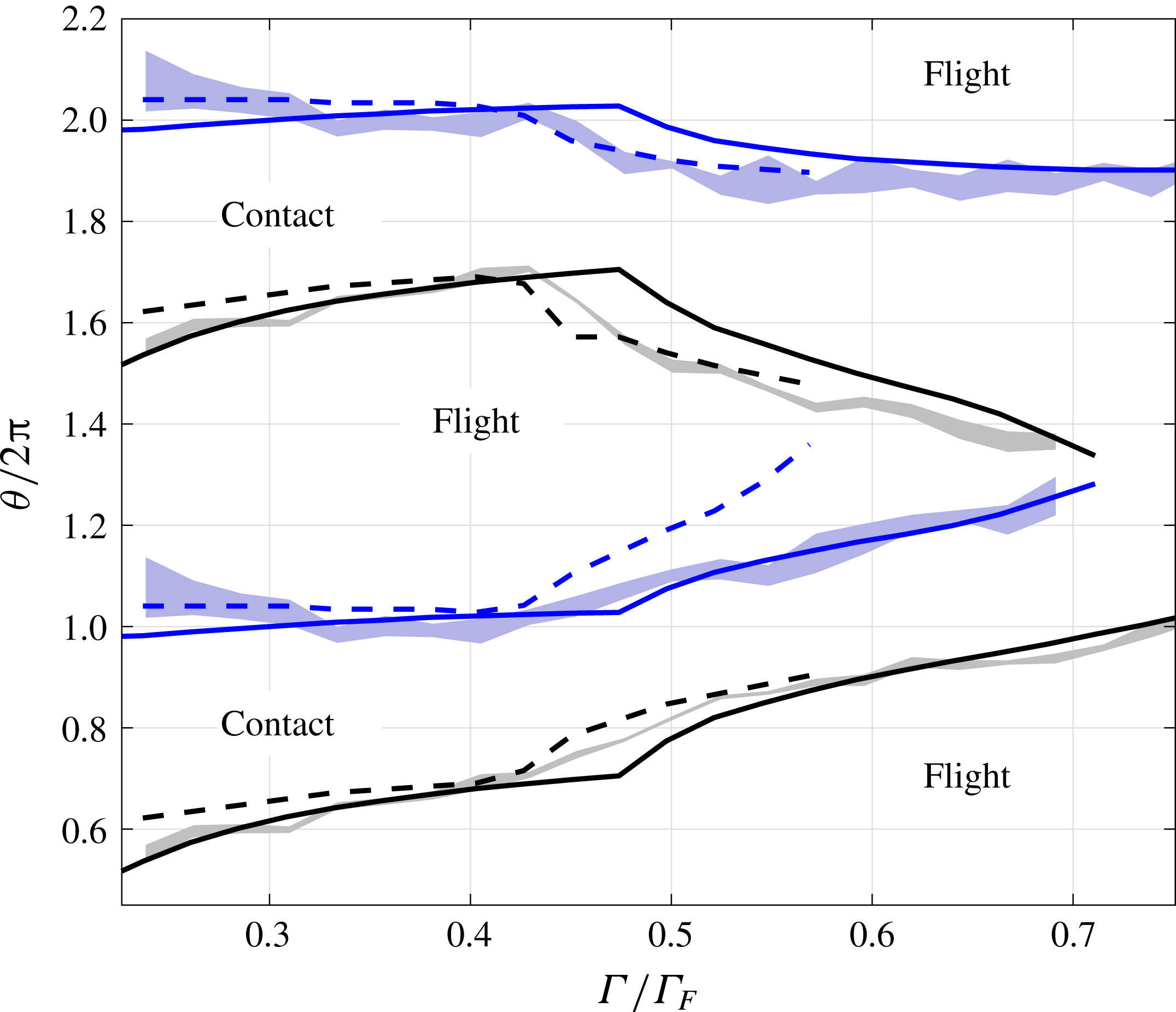
The experimental data in figure 11 correspond to a more recent experimental result which used more reliable techniques to determine contact. In particular, we notice that for
 $\unicode[STIX]{x1D6FA}=0.8$
and
$\unicode[STIX]{x1D6FA}=0.8$
and
 $0.5<\unicode[STIX]{x1D6E4}/\unicode[STIX]{x1D6E4}_{F}<0.69$
, Damiano (Reference Damiano2015) reports a
$0.5<\unicode[STIX]{x1D6E4}/\unicode[STIX]{x1D6E4}_{F}<0.69$
, Damiano (Reference Damiano2015) reports a
 $(2,2)$
bouncing mode while Wind-Willansen et al. (Reference Wind-Willansen, Moláček, Harris and Bush2013) reports a
$(2,2)$
bouncing mode while Wind-Willansen et al. (Reference Wind-Willansen, Moláček, Harris and Bush2013) reports a
 $(2,1)^{1}$
mode. This supports our claim that in this regime it is hard to distinguish between the two, which was the base for our choice of the introduction of a hashed region in figure 10. Our simulations show better agreement with the more recent experimental results and better agreement with experiments than the logarithmic spring model.
$(2,1)^{1}$
mode. This supports our claim that in this regime it is hard to distinguish between the two, which was the base for our choice of the introduction of a hashed region in figure 10. Our simulations show better agreement with the more recent experimental results and better agreement with experiments than the logarithmic spring model.
Finally, we are able to compare our wave field predictions to the experimental observations reported in Damiano et al. (Reference Damiano, Brun, Harris, Galeano-Rios and Bush2016), where a surface Schlieren method was used to measure wave topography. Figure 12 shows a comparison of the radial profiles obtained by measurements and simulations. We note that the agreement is reasonable, especially considering the fact that there is no fit in phase. However, numerically computed waves tend to be larger in amplitude. This discrepancy between theory and experiment probably arises from our quasi-potential approximation and the simple form of the dissipation. In this approximation, all of the forcing due to droplet impact is deposited into wave modes, whereas it is probable that in reality non-wave-like vortical motions are also generated and rapidly dissipated, resulting in a smaller total wave response.
Comparison of the radial profiles of the experimental measurements (Damiano et al.
Reference Damiano, Brun, Harris, Galeano-Rios and Bush2016) of wave topography (black) for a bouncer of
 $\unicode[STIX]{x1D6FA}=0.8$
and
$\unicode[STIX]{x1D6FA}=0.8$
and
 $\unicode[STIX]{x1D6E4}=3.25$
, i.e. just below the walking threshold, to the predictions of the model presented here (grey) for the same shaking. The vicinity of the origin is not shown, since in this region, the presence of the drop interferes with the measurements.
$\unicode[STIX]{x1D6E4}=3.25$
, i.e. just below the walking threshold, to the predictions of the model presented here (grey) for the same shaking. The vicinity of the origin is not shown, since in this region, the presence of the drop interferes with the measurements.

5 Conclusions
From the free-surface Navier–Stokes equations we derive a linear set of partial differential equations to model the motion of the free surface under a high-Reynolds-number approximation and couple it to the motion of the impacting hydrophobic solid through the consistent adjustment of the contact area and matching velocities. From this the pressure on the solid can be obtained, coupling back to its equation of motion. The model does not require explicitly that the impacting object be a sphere; however, calculations of the motion of the fluid and solid are largely simplified in axisymmetric cases since we do not need to calculate rotational solid motion and, provided the surface is axisymmetric initially, the net forces are vertical. In the future we wish to extend the applicability of this model weakening some of these assumptions, in particular for the case of walking droplets.
The resulting problem involves mixed boundary conditions at the surface of the fluid. In order to reduce the usual free-surface potential flow problem to a problem on the boundary alone one can define a Dirichlet-to-Neumann operator that physically corresponds to, given the tangential velocity of the surface, finding the normal velocity. The impact of a solid creates mixed conditions, as on the pressed part of the interface the constraint that the fluid surface coincides with the solid modifies the free-surface boundary conditions. We note that the domain of the impact is, a priori, unknown and needs to be found as part of the problem. Here, we present a derivation of the Neumann-to-Dirichlet map for the case of the negative half-space, which we obtain by a modification of the case presented in Forbes (Reference Forbes1989). We then proceed to invert this map analytically, arriving at a singular integral representation for desired operator. We prove the convergence of the singular integral in the principal value sense. The strategy we use has the advantage of not requiring the inversion of a full matrix and also yields a fast decaying kernel. Moreover; knowing the kernel explicitly, provides the chance to carefully design approximations of the operator, e.g. by integrating the kernel exactly and interpolating only the smooth argument function.
We ignore the dynamics of this air cushion between the solid and the bath and simply assume that the pressure on the solid is the one necessary to produce the consistent displacement on the fluid. This is a dynamic version of the situation presented in Keller (Reference Keller1998); with the peculiarity that here the contact angle is assumed to be
 $\unicode[STIX]{x03C0}$
at all times here. We could, in principle, model the impact of a non-hydrophobic solid, provided we had a suitable model of contact angle dynamics. Given the importance of surface tension due to the size of the impacting body, in calculating the pressure, we do not assume small curvature on the impacted portion of the free surface as it is determined exactly by the curvature of the wetted surface of the object.
$\unicode[STIX]{x03C0}$
at all times here. We could, in principle, model the impact of a non-hydrophobic solid, provided we had a suitable model of contact angle dynamics. Given the importance of surface tension due to the size of the impacting body, in calculating the pressure, we do not assume small curvature on the impacted portion of the free surface as it is determined exactly by the curvature of the wetted surface of the object.
Impact problems belong to the class of non-smooth dynamical systems since the evolution has a switch when a particular constraint (i.e. the non-overlapping of the fluid and solid) becomes active. As we enforce this constraint exactly, it implies that implicit-in-time methods are appropriate. Once we have discretised the spatial domain there results a closed system of linear equations, provided we know exactly which points are in contact. The contact area itself is part of what needs to be determined, and this is done through an adaptive local search to find the optimal contact area satisfying the constraints and contact angle conditions.
As a result, we obtain a fully predictive model for the axisymmetric impact of a smooth, convex solid onto a free surface at high Reynolds numbers. Comparisons to experimental results of hydrophobic sphere impact reported in Lee & Kim (Reference Lee and Kim2008) show that this relatively simple modelling can produce remarkably good results. More comprehensive experiments and comparisons are currently underway in this case.
The application of this hydrophobic impact model to the problem of bouncing droplets produces the first model that yields a prediction of the evolution of the ‘contact’ area and pressure field in accordance with the evolution of the free surface, free of any parameterisations. In previous models (Moláček & Bush Reference Moláček and Bush2013a ,Reference Moláček and Bush b ; Milewski et al. Reference Milewski, Galeano-Rios, Nachbin and Bush2015), a nonlinear spring was assumed to model the forces between droplet and bath, which required the fitting of three parameters. Whilst, that model also produced excellent agreement with experiments it did not enforce the impact constraint we consider here, and hence the bath and the drop did not always coincide during impact. The present work, does away with the need of a prescribed spring model for the forces and therefore simultaneously reduces assumptions and matches more accurately the experiments presented in Wind-Willansen et al. (Reference Wind-Willansen, Moláček, Harris and Bush2013), Damiano (Reference Damiano2015) and Damiano et al. (Reference Damiano, Brun, Harris, Galeano-Rios and Bush2016). Moreover, imposing consistent displacements of the impacting bodies ensures that energy is transferred between the impacting masses with no spurious loss due to the impact modelling.
The method presented here could be modified to be applied to more complex scenarios, including waves propagating in shallower water or a varying bottom topography. For simple geometries, this can be accomplished using the method of images. More interestingly a domain decomposition method can be used to solve the case of a sharp change in depth. The study of these generalisations are part of ongoing research.
It is in principle also possible to remove the axial symmetry restrictions to model the impacts of non-axisymmetric objects or to model oblique impacts. However, for the case of walking droplets, a simpler approach would be to exploit the scale separation between the impact and the waves, and to superimpose axisymmetric impacts at different locations to produce a non-axisymmetric free surface. This has been the strategy adopted by all previous models for walkers (Bush Reference Bush2015), and also could be combined with a ‘skidding friction’ term to model horizontal drag.
Other possible improvements would be to model the air layer dynamics and resulting friction (see Brenner Reference Brenner1961) and modelling contact angle dynamics for the impact of non-hydrophobic solids. Lastly one could also introduce droplet deformation, which gains in importance with larger droplets. Computational efficiency might also be improved with the use of an irregular spatial mesh, since in the drop experiment it is observed that, immediately away from the droplet, only wavelengths comparable to the Faraday wavelength need to be resolved.
Acknowledgements
We thank A. Damiano for sharing the experimental data for figure 11, which he obtained as part of his M.Sc. work. C.A.G.-R. and P.A.M. gratefully acknowledge support through the EPSRC project EP/N018176/1. C.A.G.-R. was also supported by ANP award COMPETRO PRH32 and PCI award 454798/2015-6 at IMPA, and P.A.M. by the CNPq Science Without Borders award 402178/2012-2. J.-M.V.-B. gratefully acknowledges support through the EPSRC project EP/N018559/1.
Appendix A. The Dirichlet-to-Neumann map
Let
 $\unicode[STIX]{x1D719}(x,y,z)$
be a smooth solution of Laplace’s equation (2.20a
) that satisfies
$\unicode[STIX]{x1D719}(x,y,z)$
be a smooth solution of Laplace’s equation (2.20a
) that satisfies
 $$\begin{eqnarray}\lim _{|\boldsymbol{p}|\rightarrow \infty }|\boldsymbol{p}|^{1+\unicode[STIX]{x1D6FF}}\unicode[STIX]{x1D719}(\boldsymbol{p})=0\quad \text{and}\quad \lim _{|\boldsymbol{p}|\rightarrow \infty }|\boldsymbol{p}|^{1+\unicode[STIX]{x1D6FF}}\unicode[STIX]{x1D735}\unicode[STIX]{x1D719}(\boldsymbol{p})=0,\end{eqnarray}$$
for some
 $\unicode[STIX]{x1D6FF}>0$
. Given any
$\unicode[STIX]{x1D6FF}>0$
. Given any
 $\boldsymbol{r}=(x,y)$
, we can define
$\boldsymbol{r}=(x,y)$
, we can define
 $\boldsymbol{p}_{\boldsymbol{r}}=(x,y,0)$
, and
$\boldsymbol{p}_{\boldsymbol{r}}=(x,y,0)$
, and
 $$\begin{eqnarray}\unicode[STIX]{x1D701}_{\boldsymbol{r}}(\boldsymbol{q})={\displaystyle \frac{1}{|\boldsymbol{p}_{\boldsymbol{r}}-\boldsymbol{q}|}},\end{eqnarray}$$
the fundamental solution to the three-dimensional Laplacian centred in
 $\boldsymbol{p}_{\boldsymbol{r}}$
, where
$\boldsymbol{p}_{\boldsymbol{r}}$
, where
 $\boldsymbol{q}=(x^{\prime },y^{\prime },z^{\prime })$
. We also define the compact domain of integration
$\boldsymbol{q}=(x^{\prime },y^{\prime },z^{\prime })$
. We also define the compact domain of integration
 $\unicode[STIX]{x1D6FA}^{\boldsymbol{r}}$
shown in figure 13.
$\unicode[STIX]{x1D6FA}^{\boldsymbol{r}}$
shown in figure 13.
 $\unicode[STIX]{x1D6FA}^{\boldsymbol{r}}$
is bounded by the negative half-spheres
$\unicode[STIX]{x1D6FA}^{\boldsymbol{r}}$
is bounded by the negative half-spheres
 $D_{1}$
and
$D_{1}$
and
 $D_{2}$
with centre at
$D_{2}$
with centre at
 $p_{r}$
and radii
$p_{r}$
and radii
 $r_{1}$
and
$r_{1}$
and
 $r_{2}$
, respectively; and by the plane annulus
$r_{2}$
, respectively; and by the plane annulus
 $D_{3}$
. In turn,
$D_{3}$
. In turn,
 $D_{3}$
is bounded by the circles
$D_{3}$
is bounded by the circles
 $C_{1}$
and
$C_{1}$
and
 $C_{2}$
of radii
$C_{2}$
of radii
 $r_{1}$
and
$r_{1}$
and
 $r_{2}$
.
$r_{2}$
.
Domain of integration in which we apply Green’s second identity.

We can apply Green’s second identity in
 $\unicode[STIX]{x1D6FA}^{\boldsymbol{r}}$
to functions
$\unicode[STIX]{x1D6FA}^{\boldsymbol{r}}$
to functions
 $\unicode[STIX]{x1D719}$
and
$\unicode[STIX]{x1D719}$
and
 $\unicode[STIX]{x1D701}_{\boldsymbol{r}}$
and consider the limits of
$\unicode[STIX]{x1D701}_{\boldsymbol{r}}$
and consider the limits of
 $r_{2}\rightarrow \infty$
and
$r_{2}\rightarrow \infty$
and
 $r_{1}\rightarrow 0$
; which, in view of the decay conditions (A 1) yield
$r_{1}\rightarrow 0$
; which, in view of the decay conditions (A 1) yield
 $$\begin{eqnarray}\unicode[STIX]{x1D719}(\boldsymbol{p}_{\boldsymbol{r}})={\displaystyle \frac{1}{2\unicode[STIX]{x03C0}}}\int {\displaystyle \frac{\unicode[STIX]{x1D719}_{z^{\prime }}(\boldsymbol{q})}{|\boldsymbol{p}_{\boldsymbol{r}}-\boldsymbol{q}|}}\,\text{d}S(\boldsymbol{q}).\end{eqnarray}$$
The singularity in this problem is in fact integrable, meaning that the principal value in question is just a regular integral. However, this particular form is useful to perform the inversion we desire.
We note that
 $\unicode[STIX]{x1D719}_{z}$
is also a solution to the Laplace problem and we assume for
$\unicode[STIX]{x1D719}_{z}$
is also a solution to the Laplace problem and we assume for
 $\unicode[STIX]{x1D719}_{z}$
(and
$\unicode[STIX]{x1D719}_{z}$
(and
 $\unicode[STIX]{x1D735}\unicode[STIX]{x1D719}_{z}$
) the same decay conditions as those given in (A 1) for
$\unicode[STIX]{x1D735}\unicode[STIX]{x1D719}_{z}$
) the same decay conditions as those given in (A 1) for
 $\unicode[STIX]{x1D719}$
. Thus,
$\unicode[STIX]{x1D719}$
. Thus,
 $\unicode[STIX]{x1D719}_{z}$
is subject to the exact same considerations that lead to (A 3). This yields
$\unicode[STIX]{x1D719}_{z}$
is subject to the exact same considerations that lead to (A 3). This yields
 $$\begin{eqnarray}\unicode[STIX]{x1D719}_{z}(\boldsymbol{p}_{\boldsymbol{r}})={\displaystyle \frac{1}{2\unicode[STIX]{x03C0}}}\lim _{\unicode[STIX]{x1D716}\rightarrow 0^{+}}\int _{\mathbb{R}^{2}\setminus B\left(\boldsymbol{r};\unicode[STIX]{x1D716}\right)}{\displaystyle \frac{\unicode[STIX]{x1D719}_{z^{\prime }z^{\prime }}(\boldsymbol{q})}{|\boldsymbol{p}_{\boldsymbol{r}}-\boldsymbol{q}|}}\,\text{d}S(\boldsymbol{q}),\end{eqnarray}$$
where
 $B(\boldsymbol{r};\unicode[STIX]{x1D716})=\{(x^{\prime },y^{\prime });\Vert \boldsymbol{r}-(x^{\prime },y^{\prime })\Vert <\unicode[STIX]{x1D716}\}$
, and since the differential relations of the fluid equations are assumed to hold even on the boundary, we have
$B(\boldsymbol{r};\unicode[STIX]{x1D716})=\{(x^{\prime },y^{\prime });\Vert \boldsymbol{r}-(x^{\prime },y^{\prime })\Vert <\unicode[STIX]{x1D716}\}$
, and since the differential relations of the fluid equations are assumed to hold even on the boundary, we have
 $$\begin{eqnarray}\unicode[STIX]{x1D719}_{z}(\boldsymbol{p}_{\boldsymbol{r}})={\displaystyle \frac{1}{2\unicode[STIX]{x03C0}}}\lim _{\unicode[STIX]{x1D716}\rightarrow 0^{+}}\int _{\mathbb{R}^{2}\setminus B\left(\boldsymbol{r};\unicode[STIX]{x1D716}\right)}{\displaystyle \frac{-\unicode[STIX]{x1D6E5}_{H}^{\prime }\unicode[STIX]{x1D719}(\boldsymbol{q})}{|\boldsymbol{p}_{\boldsymbol{r}}-\boldsymbol{q}|}}\,\text{d}S(\boldsymbol{q}),\end{eqnarray}$$
where
 $\unicode[STIX]{x1D6E5}_{H}^{\prime }=\unicode[STIX]{x2202}_{x^{\prime }x^{\prime }}+\unicode[STIX]{x2202}_{y^{\prime }y^{\prime }}$
.
$\unicode[STIX]{x1D6E5}_{H}^{\prime }=\unicode[STIX]{x2202}_{x^{\prime }x^{\prime }}+\unicode[STIX]{x2202}_{y^{\prime }y^{\prime }}$
.
We can rewrite equation (A 5) as
 $$\begin{eqnarray}\unicode[STIX]{x1D719}_{z}(\boldsymbol{p}_{\boldsymbol{r}})={\displaystyle \frac{1}{2\unicode[STIX]{x03C0}}}\lim _{r_{1}\rightarrow 0^{+}}\lim _{r_{2}\rightarrow \infty }I_{r_{1}}^{r_{2}},\end{eqnarray}$$
where
 $$\begin{eqnarray}I_{r_{1}}^{r_{2}}=-\int _{r_{1}\leqslant |\boldsymbol{p}_{\boldsymbol{r}}-\boldsymbol{q}|\leqslant r_{2}}{\displaystyle \frac{\unicode[STIX]{x1D6E5}_{H}^{\prime }\unicode[STIX]{x1D719}(\boldsymbol{q})}{|\boldsymbol{p}_{\boldsymbol{r}}-\boldsymbol{q}|}}\,\text{d}S(\boldsymbol{q}).\end{eqnarray}$$
We can now apply Green’s second identity to
 $\unicode[STIX]{x1D719}$
and
$\unicode[STIX]{x1D719}$
and
 $\unicode[STIX]{x1D701}_{\boldsymbol{r}}$
on the plane annulus
$\unicode[STIX]{x1D701}_{\boldsymbol{r}}$
on the plane annulus
 $D_{3}$
, while observing (A 7). This yields
$D_{3}$
, while observing (A 7). This yields
 $$\begin{eqnarray}\int _{D_{3}}^{}\unicode[STIX]{x1D719}(\boldsymbol{q})\unicode[STIX]{x1D6E5}^{\prime }{\displaystyle \frac{1}{|\boldsymbol{p}_{\boldsymbol{r}}-\boldsymbol{q}|}}\,\text{d}S(\boldsymbol{q})+I_{r_{1}}^{r_{2}}=+\int _{C_{1}\cup C_{2}}^{}\unicode[STIX]{x1D719}(\boldsymbol{q})\unicode[STIX]{x2202}_{\hat{\boldsymbol{n}}}{\displaystyle \frac{1}{|\boldsymbol{p}_{\boldsymbol{r}}-\boldsymbol{q}|}}\,\text{d}l(\boldsymbol{q})-\int _{C_{1}\cup C_{2}}^{}{\displaystyle \frac{\unicode[STIX]{x2202}_{\hat{\boldsymbol{n}}}\unicode[STIX]{x1D719}(\boldsymbol{q})}{|\boldsymbol{p}_{\boldsymbol{r}}-\boldsymbol{q}|}}\,\text{d}l(\boldsymbol{q}),\end{eqnarray}$$
where
 $r_{1}$
,
$r_{1}$
,
 $r_{2}$
,
$r_{2}$
,
 $C_{1}$
,
$C_{1}$
,
 $C_{2}$
and
$C_{2}$
and
 $D_{3}$
are as shown in figure 13, and
$D_{3}$
are as shown in figure 13, and
 $\hat{\boldsymbol{n}}$
is the outward pointing unit normal to
$\hat{\boldsymbol{n}}$
is the outward pointing unit normal to
 $C_{1}$
and
$C_{1}$
and
 $C_{2}$
. We note that
$C_{2}$
. We note that
 $$\begin{eqnarray}\unicode[STIX]{x1D6E5}^{\prime }{\displaystyle \frac{1}{|\boldsymbol{p}_{\boldsymbol{r}}-\boldsymbol{q}|}}={\displaystyle \frac{1}{|\boldsymbol{p}_{\boldsymbol{r}}-\boldsymbol{q}|^{3}}}\quad \text{and}\quad \unicode[STIX]{x2202}_{\hat{\boldsymbol{n}}}{\displaystyle \frac{1}{|\boldsymbol{p}_{\boldsymbol{r}}-\boldsymbol{q}|}}=\pm {\displaystyle \frac{1}{|\boldsymbol{p}_{\boldsymbol{r}}-\boldsymbol{q}|^{2}}},\end{eqnarray}$$
where
 $\unicode[STIX]{x2202}_{\hat{\boldsymbol{n}}}(1/|\boldsymbol{p}_{\boldsymbol{r}}-\boldsymbol{q}|)$
is positive on
$\unicode[STIX]{x2202}_{\hat{\boldsymbol{n}}}(1/|\boldsymbol{p}_{\boldsymbol{r}}-\boldsymbol{q}|)$
is positive on
 $C_{1}$
and negative on
$C_{1}$
and negative on
 $C_{2}$
. We thus have
$C_{2}$
. We thus have
 $$\begin{eqnarray}I_{r_{1}}^{r_{2}}=-\int _{D_{3}}^{}{\displaystyle \frac{\unicode[STIX]{x1D719}(\boldsymbol{q})}{|\boldsymbol{p}_{\boldsymbol{r}}-\boldsymbol{q}|^{3}}}\,\text{d}S(\boldsymbol{q})+J_{1}+J_{2}+K_{1}+K_{2},\end{eqnarray}$$
where
 $$\begin{eqnarray}J_{i}=-\int _{C_{i}}^{}{\displaystyle \frac{\unicode[STIX]{x2202}_{\hat{\boldsymbol{n}}}\unicode[STIX]{x1D719}(\boldsymbol{q})}{|\boldsymbol{p}_{\boldsymbol{r}}-\boldsymbol{q}|}}\,\text{d}l(\boldsymbol{q})\quad \text{and}\quad K_{i}=(-1)^{i+1}\int _{C_{i}}{\displaystyle \frac{\unicode[STIX]{x1D719}(\boldsymbol{q})}{|\boldsymbol{p}_{\boldsymbol{r}}-\boldsymbol{q}|^{2}}}\,\text{d}l(\boldsymbol{q}).\end{eqnarray}$$
We note now that
 $J_{2}$
and
$J_{2}$
and
 $K_{2}$
converge to zero as
$K_{2}$
converge to zero as
 $r_{2}\rightarrow \infty$
on account of the decay of
$r_{2}\rightarrow \infty$
on account of the decay of
 $\unicode[STIX]{x1D719}$
and its derivatives. In addition, we can easily see that
$\unicode[STIX]{x1D719}$
and its derivatives. In addition, we can easily see that
 $J_{1}$
is equals to
$J_{1}$
is equals to
 $$\begin{eqnarray}-\int _{0}^{2\unicode[STIX]{x03C0}}{\displaystyle \frac{\unicode[STIX]{x1D735}\unicode[STIX]{x1D719}(\boldsymbol{q})\boldsymbol{\cdot }\hat{\boldsymbol{n}}r_{1}\,\text{d}\unicode[STIX]{x1D703}}{r_{1}}}=-\int _{0}^{2\unicode[STIX]{x03C0}}\unicode[STIX]{x1D735}\unicode[STIX]{x1D719}(\boldsymbol{p}_{\boldsymbol{ r}})\boldsymbol{\cdot }\hat{n}\,\text{d}\unicode[STIX]{x1D703}-r_{1}\int _{0}^{2\unicode[STIX]{x03C0}}\boldsymbol{e}(\boldsymbol{q})\boldsymbol{\cdot }\hat{\boldsymbol{n}}\,\text{d}\unicode[STIX]{x1D703},\end{eqnarray}$$
where
 $\boldsymbol{e}(\boldsymbol{q})\rightarrow 0$
when
$\boldsymbol{e}(\boldsymbol{q})\rightarrow 0$
when
 $r_{1}\rightarrow 0$
. The first integral on the right-hand side of (A 12) is identically zero, due to symmetry of the normal along
$r_{1}\rightarrow 0$
. The first integral on the right-hand side of (A 12) is identically zero, due to symmetry of the normal along
 $C_{1}$
, the second integral is bounded and thus
$C_{1}$
, the second integral is bounded and thus
 $J_{1}\rightarrow 0$
when
$J_{1}\rightarrow 0$
when
 $r_{1}\rightarrow 0$
.
$r_{1}\rightarrow 0$
.
We now rewrite
 $K_{1}$
as
$K_{1}$
as
 $$\begin{eqnarray}K_{1}=\int _{0}^{2\unicode[STIX]{x03C0}}{\displaystyle \frac{\unicode[STIX]{x1D719}(\boldsymbol{q})-\unicode[STIX]{x1D719}(\boldsymbol{p}_{\boldsymbol{r}})}{r_{1}^{2}}}r_{1}\,\text{d}\unicode[STIX]{x1D703}+\unicode[STIX]{x1D719}(\boldsymbol{p}_{\boldsymbol{r}})\int _{0}^{2\unicode[STIX]{x03C0}}{\displaystyle \frac{1}{r_{1}^{2}}}r_{1}\,\text{d}\unicode[STIX]{x1D703}.\end{eqnarray}$$
Note now that the first integral on the right-hand side of (A 13) can be reformulated as
 $$\begin{eqnarray}\int _{0}^{2\unicode[STIX]{x03C0}}{\displaystyle \frac{\unicode[STIX]{x1D719}(\boldsymbol{q})-\unicode[STIX]{x1D719}(\boldsymbol{p}_{\boldsymbol{r}})}{r_{1}}}\,\text{d}\unicode[STIX]{x1D703}=\int _{0}^{2\unicode[STIX]{x03C0}}{\displaystyle \frac{\unicode[STIX]{x1D735}\unicode[STIX]{x1D719}(\boldsymbol{p}_{\boldsymbol{r}})\boldsymbol{\cdot }(\boldsymbol{q}-\boldsymbol{p}_{\boldsymbol{r}})}{r_{1}}}\,\text{d}\unicode[STIX]{x1D703}+\int _{0}^{2\unicode[STIX]{x03C0}}{\displaystyle \frac{\unicode[STIX]{x1D709}(\boldsymbol{q}-\boldsymbol{p}_{\boldsymbol{r}})r_{1}}{r_{1}}}\,\text{d}\unicode[STIX]{x1D703},\end{eqnarray}$$
where
 $\unicode[STIX]{x1D709}(\boldsymbol{q}-\boldsymbol{p}_{\boldsymbol{r}})\rightarrow 0$
as
$\unicode[STIX]{x1D709}(\boldsymbol{q}-\boldsymbol{p}_{\boldsymbol{r}})\rightarrow 0$
as
 $r_{1}\rightarrow 0$
. The first integral in (A 14) is identically null by the same argument used for the first integral for (A 12), and the second integral converges to zero when
$r_{1}\rightarrow 0$
. The first integral in (A 14) is identically null by the same argument used for the first integral for (A 12), and the second integral converges to zero when
 $r_{1}\rightarrow 0$
.
$r_{1}\rightarrow 0$
.
We now note that the second term on the right-hand side of (A 13) can be restated as
 $$\begin{eqnarray}\unicode[STIX]{x1D719}(\boldsymbol{p}_{\boldsymbol{r}})\int _{0}^{2\unicode[STIX]{x03C0}}{\displaystyle \frac{1}{r_{1}}}\,\text{d}\unicode[STIX]{x1D703}=\unicode[STIX]{x1D719}(\boldsymbol{p}_{\boldsymbol{r}})\int _{0}^{2\unicode[STIX]{x03C0}}\int _{r_{1}}^{\infty }{\displaystyle \frac{1}{r^{3}}}r\,\text{d}r\,\text{d}\unicode[STIX]{x1D703}=\int _{|\boldsymbol{q}-\boldsymbol{p}_{\boldsymbol{r}}|>r_{1}}{\displaystyle \frac{\unicode[STIX]{x1D719}(\boldsymbol{p}_{\boldsymbol{r}})}{|\boldsymbol{p}_{\boldsymbol{r}}-\boldsymbol{q}|^{3}}}\,\text{d}S(\boldsymbol{q}).\end{eqnarray}$$
Finally, we have
 $$\begin{eqnarray}\lim _{r_{2}\rightarrow \infty }I_{r_{1}}^{r_{2}}=-\int _{|\boldsymbol{q}-\boldsymbol{p}_{\boldsymbol{r}}|>r_{1}}{\displaystyle \frac{\unicode[STIX]{x1D719}(\boldsymbol{q})}{|\boldsymbol{p}_{\boldsymbol{r}}-\boldsymbol{q}|^{3}}}\,\text{d}S(\boldsymbol{q})+J_{1}+K_{1},\end{eqnarray}$$
which together with (A 6) yields
 $$\begin{eqnarray}\unicode[STIX]{x1D719}_{z}(\boldsymbol{p}_{\boldsymbol{r}})={\displaystyle \frac{1}{2\unicode[STIX]{x03C0}}}\lim _{r_{1}\rightarrow 0^{+}}\left(-\int _{|\boldsymbol{q}-\boldsymbol{p}_{\boldsymbol{r}}|>r_{1}}{\displaystyle \frac{\unicode[STIX]{x1D719}(\boldsymbol{q})}{|\boldsymbol{p}_{\boldsymbol{r}}-\boldsymbol{q}|^{3}}}\,\text{d}S(\boldsymbol{q})+\int _{|\boldsymbol{q}-\boldsymbol{p}_{\boldsymbol{r}}|>r_{1}}{\displaystyle \frac{\unicode[STIX]{x1D719}(\boldsymbol{p}_{\boldsymbol{r}})}{|\boldsymbol{p}_{\boldsymbol{r}}-\boldsymbol{q}|^{3}}}\,\text{d}S(\boldsymbol{q})\right),\end{eqnarray}$$
i.e.
 $$\begin{eqnarray}N\unicode[STIX]{x1D719}(\boldsymbol{p}_{\boldsymbol{r}})=\unicode[STIX]{x1D719}_{z}(\boldsymbol{p}_{\boldsymbol{r}})={\displaystyle \frac{1}{2\unicode[STIX]{x03C0}}}P.V.\int {\displaystyle \frac{\unicode[STIX]{x1D719}(\boldsymbol{p}_{\boldsymbol{r}})-\unicode[STIX]{x1D719}(\boldsymbol{q})}{|\boldsymbol{p}_{\boldsymbol{r}}-\boldsymbol{q}|^{3}}}\,\text{d}S(\boldsymbol{q}).\end{eqnarray}$$
A.1 Convergence of the singular integral in the
 $N$
map formula
$N$
map formula

We consider
 $$\begin{eqnarray}P.V.\int {\displaystyle \frac{\unicode[STIX]{x1D719}(\boldsymbol{p}_{\boldsymbol{r}})-\unicode[STIX]{x1D719}(\boldsymbol{q})}{|\boldsymbol{p}_{\boldsymbol{r}}-\boldsymbol{q}|^{3}}}\,\text{d}S(\boldsymbol{q})=\lim _{\unicode[STIX]{x1D716}\rightarrow 0}\int _{|\boldsymbol{p}_{\boldsymbol{r}}-\boldsymbol{q}|>\unicode[STIX]{x1D716}}{\displaystyle \frac{\unicode[STIX]{x1D719}(\boldsymbol{p}_{\boldsymbol{r}})-\unicode[STIX]{x1D719}(\boldsymbol{q})}{|\boldsymbol{p}_{\boldsymbol{r}}-\boldsymbol{q}|^{3}}}\,\text{d}S(\boldsymbol{q}),\end{eqnarray}$$
and we note that given any radius
 $r_{0}>0$
arbitrarily small, for any bounded
$r_{0}>0$
arbitrarily small, for any bounded
 $\unicode[STIX]{x1D719}$
of class
$\unicode[STIX]{x1D719}$
of class
 $C^{2}$
we have
$C^{2}$
we have
 $$\begin{eqnarray}P.V.\int {\displaystyle \frac{\unicode[STIX]{x1D719}(\boldsymbol{p}_{\boldsymbol{r}})-\unicode[STIX]{x1D719}(\boldsymbol{q})}{|\boldsymbol{p}_{\boldsymbol{r}}-\boldsymbol{q}|^{3}}}\,\text{d}S(\boldsymbol{q})=L_{1}+L_{2},\end{eqnarray}$$
where
 $$\begin{eqnarray}L_{1}=\lim _{\unicode[STIX]{x1D716}\rightarrow 0}\int _{r_{0}>|\boldsymbol{p}_{\boldsymbol{r}}-\boldsymbol{q}|>\unicode[STIX]{x1D716}}{\displaystyle \frac{\unicode[STIX]{x1D719}(\boldsymbol{p}_{\boldsymbol{r}})-\unicode[STIX]{x1D719}(\boldsymbol{q})}{|\boldsymbol{p}_{\boldsymbol{r}}-\boldsymbol{q}|^{3}}}\,\text{d}S(\boldsymbol{q})\end{eqnarray}$$
and
 $$\begin{eqnarray}L_{2}=\int _{|\boldsymbol{p}_{\boldsymbol{r}}-\boldsymbol{q}|>r_{0}}{\displaystyle \frac{\unicode[STIX]{x1D719}(\boldsymbol{p}_{\boldsymbol{r}})-\unicode[STIX]{x1D719}(\boldsymbol{q})}{|\boldsymbol{p}_{\boldsymbol{r}}-\boldsymbol{q}|^{3}}}\,\text{d}S(\boldsymbol{q}).\end{eqnarray}$$
Here
 $L_{2}$
is bounded, and we can prove that
$L_{2}$
is bounded, and we can prove that
 $L_{1}$
is bounded. First we note that
$L_{1}$
is bounded. First we note that
 $$\begin{eqnarray}\unicode[STIX]{x1D719}(\boldsymbol{p}_{\boldsymbol{r}})-\unicode[STIX]{x1D719}(\boldsymbol{q})=-\unicode[STIX]{x1D735}\unicode[STIX]{x1D719}(\boldsymbol{p}_{\boldsymbol{r}})(\boldsymbol{q}-\boldsymbol{p}_{\boldsymbol{r}})-{\textstyle \frac{1}{2}}(\boldsymbol{q}-(\boldsymbol{p}_{\boldsymbol{r}}))^{\text{T}}H(\boldsymbol{p}_{\boldsymbol{r}})(\boldsymbol{q}-\boldsymbol{p}_{\boldsymbol{r}})-\unicode[STIX]{x1D709}(\boldsymbol{q}-\boldsymbol{p}_{\boldsymbol{r}})|\boldsymbol{q}-\boldsymbol{p}_{\boldsymbol{r}}|^{2},\end{eqnarray}$$
where
 $H$
is the Hessian matrix of
$H$
is the Hessian matrix of
 $\unicode[STIX]{x1D719}$
and
$\unicode[STIX]{x1D719}$
and
 $\unicode[STIX]{x1D709}(\boldsymbol{q}-\boldsymbol{p}_{\boldsymbol{r}})\rightarrow 0$
as
$\unicode[STIX]{x1D709}(\boldsymbol{q}-\boldsymbol{p}_{\boldsymbol{r}})\rightarrow 0$
as
 $\boldsymbol{q}\rightarrow \boldsymbol{p}_{\boldsymbol{r}}$
. We then define
$\boldsymbol{q}\rightarrow \boldsymbol{p}_{\boldsymbol{r}}$
. We then define
 $$\begin{eqnarray}N_{1}=\lim _{\unicode[STIX]{x1D716}\rightarrow 0}\int _{\unicode[STIX]{x1D716}}^{r_{0}}\int _{0}^{2\unicode[STIX]{x03C0}}{\displaystyle \frac{-\unicode[STIX]{x1D735}\unicode[STIX]{x1D719}(\boldsymbol{p}_{\boldsymbol{r}})(\boldsymbol{q}-\boldsymbol{p}_{\boldsymbol{r}})}{r^{2}}}\,\text{d}\unicode[STIX]{x1D703}\,\text{d}r,\end{eqnarray}$$
 $$\begin{eqnarray}N_{2}=\lim _{\unicode[STIX]{x1D716}\rightarrow 0}\int _{\unicode[STIX]{x1D716}}^{r_{0}}\int _{0}^{2\unicode[STIX]{x03C0}}-{\displaystyle \frac{1}{2}}{\displaystyle \frac{(\boldsymbol{q}-\boldsymbol{p}_{\boldsymbol{r}})^{\text{T}}}{|\boldsymbol{q}-\boldsymbol{p}_{\boldsymbol{r}}|}}H\unicode[STIX]{x1D719}(\boldsymbol{p}_{\boldsymbol{r}}){\displaystyle \frac{(\boldsymbol{q}-\boldsymbol{p}_{\boldsymbol{r}})}{|\boldsymbol{q}-\boldsymbol{p}_{\boldsymbol{r}}|}}\,\text{d}\unicode[STIX]{x1D703}\,\text{d}r\end{eqnarray}$$
and
 $$\begin{eqnarray}N_{3}=\lim _{\unicode[STIX]{x1D716}\rightarrow 0}\int _{0}^{2\unicode[STIX]{x03C0}}\int _{\unicode[STIX]{x1D716}}^{r_{0}}-\unicode[STIX]{x1D709}(r,\unicode[STIX]{x1D703})\,\text{d}r\,\text{d}\unicode[STIX]{x1D703},\end{eqnarray}$$
where
 $(r,\unicode[STIX]{x1D703})$
is
$(r,\unicode[STIX]{x1D703})$
is
 $(\boldsymbol{q}-\boldsymbol{p}_{\boldsymbol{r}})$
in polar coordinates,
$(\boldsymbol{q}-\boldsymbol{p}_{\boldsymbol{r}})$
in polar coordinates,
 $\unicode[STIX]{x1D709}(\boldsymbol{q})\rightarrow 0$
as
$\unicode[STIX]{x1D709}(\boldsymbol{q})\rightarrow 0$
as
 $\boldsymbol{q}\rightarrow \boldsymbol{p}_{\boldsymbol{r}}$
. We note that the inner integral in
$\boldsymbol{q}\rightarrow \boldsymbol{p}_{\boldsymbol{r}}$
. We note that the inner integral in
 $N_{1}$
is identically null, and that
$N_{1}$
is identically null, and that
 $N_{2}$
and
$N_{2}$
and
 $N_{3}$
are bounded. Moreover, by (A 23),
$N_{3}$
are bounded. Moreover, by (A 23),
 $L_{1}=N_{1}+N_{2}+N_{3}$
, and thus the boundedness of
$L_{1}=N_{1}+N_{2}+N_{3}$
, and thus the boundedness of
 $L_{1}$
follows from all the
$L_{1}$
follows from all the
 $N_{i}$
being bounded and the convergence of the singular integral of the
$N_{i}$
being bounded and the convergence of the singular integral of the
 $N$
operator follows from the convergence of
$N$
operator follows from the convergence of
 $L_{1}$
and
$L_{1}$
and
 $L_{2}$
.
$L_{2}$
.
Appendix B. Matrix representations of the integral and differential operators
We recall the expression of the two-dimensional Laplacian in polar coordinates, given by
 $$\begin{eqnarray}\unicode[STIX]{x1D6E5}_{H}\unicode[STIX]{x1D719}(r,\unicode[STIX]{x1D703})={\displaystyle \frac{\unicode[STIX]{x2202}^{2}}{\unicode[STIX]{x2202}r^{2}}}\unicode[STIX]{x1D719}+{\displaystyle \frac{1}{r}}{\displaystyle \frac{\unicode[STIX]{x2202}}{\unicode[STIX]{x2202}r}}\unicode[STIX]{x1D719}+{\displaystyle \frac{1}{r^{2}}}{\displaystyle \frac{\unicode[STIX]{x2202}^{2}}{\unicode[STIX]{x2202}\unicode[STIX]{x1D703}^{2}}}\unicode[STIX]{x1D719},\end{eqnarray}$$
which for radial functions yields
 $$\begin{eqnarray}\unicode[STIX]{x1D6E5}_{H}\unicode[STIX]{x1D719}(r,\unicode[STIX]{x1D703})={\displaystyle \frac{\unicode[STIX]{x2202}^{2}}{\unicode[STIX]{x2202}r^{2}}}\unicode[STIX]{x1D719}+{\displaystyle \frac{1}{r}}{\displaystyle \frac{\unicode[STIX]{x2202}}{\unicode[STIX]{x2202}r}}\unicode[STIX]{x1D719}.\end{eqnarray}$$
We note that (B 2) does not provide a rule to estimate
 $\unicode[STIX]{x1D6E5}_{H}$
at the origin, thus for this point we use the second-order approximation that corresponds to the five-points stencil discrete Laplacian, which for a radial function yields
$\unicode[STIX]{x1D6E5}_{H}$
at the origin, thus for this point we use the second-order approximation that corresponds to the five-points stencil discrete Laplacian, which for a radial function yields
 $$\begin{eqnarray}\unicode[STIX]{x1D6E5}_{H}\unicode[STIX]{x1D719}\left(0\right)\approx 4{\displaystyle \frac{\unicode[STIX]{x1D719}\left(\unicode[STIX]{x1D6FF}r\right)-\unicode[STIX]{x1D719}\left(0\right)}{\unicode[STIX]{x1D6FF}r^{2}}},\end{eqnarray}$$
where
 $\unicode[STIX]{x1D6FF}r$
is the spacing of the radial mesh. For
$\unicode[STIX]{x1D6FF}r$
is the spacing of the radial mesh. For
 $i=1,2,\ldots ,n_{r}-1$
we use
$i=1,2,\ldots ,n_{r}-1$
we use
 $$\begin{eqnarray}\unicode[STIX]{x1D6E5}_{H}\unicode[STIX]{x1D719}(\text{i}\unicode[STIX]{x1D6FF}r)\approx {\displaystyle \frac{\unicode[STIX]{x1D719}((i+1)\unicode[STIX]{x1D6FF}r)-2\unicode[STIX]{x1D719}(\text{i}\unicode[STIX]{x1D6FF}r)+\unicode[STIX]{x1D719}((i-1)\unicode[STIX]{x1D6FF}r)}{\unicode[STIX]{x1D6FF}r^{2}}}+{\displaystyle \frac{\unicode[STIX]{x1D719}((i+1)\unicode[STIX]{x1D6FF}r)-\unicode[STIX]{x1D719}((i-1)\unicode[STIX]{x1D6FF}r)}{2\text{i}\unicode[STIX]{x1D6FF}r^{2}}},\end{eqnarray}$$
which is based on (B 2) and is of second order as well. Based on the decay condition at infinity, we assume the last node of the radial mesh satisfies
 $\unicode[STIX]{x1D702}(R,t)=0$
,
$\unicode[STIX]{x1D702}(R,t)=0$
,
 $\unicode[STIX]{x1D719}(R,t)=0$
, where
$\unicode[STIX]{x1D719}(R,t)=0$
, where
 $R=n_{r}\unicode[STIX]{x1D6FF}r$
.
$R=n_{r}\unicode[STIX]{x1D6FF}r$
.
(a) Schematics of the meshes used to approximate the singular integrals. The black lines correspond to the radial mesh, i.e. the level sets of function
 $\unicode[STIX]{x1D719}$
sampled at each discrete point
$\unicode[STIX]{x1D719}$
sampled at each discrete point
 $\text{i}\unicode[STIX]{x1D6FF}r$
. The grey lines correspond to a polar mesh used to estimate
$\text{i}\unicode[STIX]{x1D6FF}r$
. The grey lines correspond to a polar mesh used to estimate
 $N\unicode[STIX]{x1D719}(\text{i}\unicode[STIX]{x1D6FF}r)$
. The (♦) marker shows a generic point on the polar mesh. The values of
$N\unicode[STIX]{x1D719}(\text{i}\unicode[STIX]{x1D6FF}r)$
. The (♦) marker shows a generic point on the polar mesh. The values of
 $\unicode[STIX]{x1D719}$
at the two thicker black lines, and possibly other neighbouring lines, are used to interpolate the
$\unicode[STIX]{x1D719}$
at the two thicker black lines, and possibly other neighbouring lines, are used to interpolate the
 $\unicode[STIX]{x1D719}$
at point (♦). (b) Enlarged view of (a). The grey dashed lines bound the region where
$\unicode[STIX]{x1D719}$
at point (♦). (b) Enlarged view of (a). The grey dashed lines bound the region where
 $\unicode[STIX]{x1D719}$
is taken to be constant when approximating
$\unicode[STIX]{x1D719}$
is taken to be constant when approximating
 $N\unicode[STIX]{x1D719}(\text{i}\unicode[STIX]{x1D6FF}r)$
. This constant value is given by the interpolation of the values of
$N\unicode[STIX]{x1D719}(\text{i}\unicode[STIX]{x1D6FF}r)$
. This constant value is given by the interpolation of the values of
 $\unicode[STIX]{x1D719}$
on lines of the radial mesh, shown above in thick black lines.
$\unicode[STIX]{x1D719}$
on lines of the radial mesh, shown above in thick black lines.

The operator
 $N$
includes a singular integral, whose convergence relies strongly on the symmetry of the kernel (see A.1), hence its numerical approximation requires a more careful approach to remove the singular behaviour exactly. To calculate
$N$
includes a singular integral, whose convergence relies strongly on the symmetry of the kernel (see A.1), hence its numerical approximation requires a more careful approach to remove the singular behaviour exactly. To calculate
 $N\unicode[STIX]{x1D719}$
at each mesh point we must use a method that preserves the cancelations that occur as the limit in (2.23) is approached. We thus use a different mesh
$N\unicode[STIX]{x1D719}$
at each mesh point we must use a method that preserves the cancelations that occur as the limit in (2.23) is approached. We thus use a different mesh
 $(r^{i},\unicode[STIX]{x1D703}^{i})$
centred at each point
$(r^{i},\unicode[STIX]{x1D703}^{i})$
centred at each point
 $r=i\unicode[STIX]{x1D6FF}r$
, with
$r=i\unicode[STIX]{x1D6FF}r$
, with
 $i=0,1,2,\ldots ,n_{r}$
, see figure 14(a). We refer to this new mesh as the polar mesh, in contrast with the radial mesh, described above.
$i=0,1,2,\ldots ,n_{r}$
, see figure 14(a). We refer to this new mesh as the polar mesh, in contrast with the radial mesh, described above.
When approximating the singular integral in
 $N$
we integrate the kernel exactly, interpolating instead the smooth function
$N$
we integrate the kernel exactly, interpolating instead the smooth function
 $\unicode[STIX]{x1D719}-\unicode[STIX]{x1D719}(i\unicode[STIX]{x1D6FF}r)$
. We thus interpolate the value of the numerator of the integrand in (A 18) at the point of interest. This interpolation is based on the neighbouring radial values, see figure 14.
$\unicode[STIX]{x1D719}-\unicode[STIX]{x1D719}(i\unicode[STIX]{x1D6FF}r)$
. We thus interpolate the value of the numerator of the integrand in (A 18) at the point of interest. This interpolation is based on the neighbouring radial values, see figure 14.
Thus, to calculate
 $N\unicode[STIX]{x1D719}(i\unicode[STIX]{x1D6FF}r)$
we proceed by approximating the value of the numerator in the integrand in (2.23) at each point of our polar mesh
$N\unicode[STIX]{x1D719}(i\unicode[STIX]{x1D6FF}r)$
we proceed by approximating the value of the numerator in the integrand in (2.23) at each point of our polar mesh
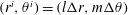 $(r^{i},\unicode[STIX]{x1D703}^{i})=(l\unicode[STIX]{x0394}r,m\unicode[STIX]{x0394}\unicode[STIX]{x1D703})$
, with
$(r^{i},\unicode[STIX]{x1D703}^{i})=(l\unicode[STIX]{x0394}r,m\unicode[STIX]{x0394}\unicode[STIX]{x1D703})$
, with
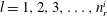 $l=1,2,3,\ldots ,n_{r}^{i}$
and
$l=1,2,3,\ldots ,n_{r}^{i}$
and
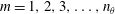 $m=1,2,3,\ldots ,n_{\unicode[STIX]{x1D703}}$
; where
$m=1,2,3,\ldots ,n_{\unicode[STIX]{x1D703}}$
; where
 $\unicode[STIX]{x0394}\unicode[STIX]{x1D703}=2\unicode[STIX]{x03C0}/n_{\unicode[STIX]{x1D703}}$
, and
$\unicode[STIX]{x0394}\unicode[STIX]{x1D703}=2\unicode[STIX]{x03C0}/n_{\unicode[STIX]{x1D703}}$
, and
 $n_{r}^{i}$
is chosen to guarantee that each polar mesh covers the radial mesh completely. In particular, for all examples presented in the previous sections we use cubic interpolation. The limit in (2.23) is approximated simply by avoiding the central point of each polar mesh, thus effectively integrating everywhere outside a circle of radius
$n_{r}^{i}$
is chosen to guarantee that each polar mesh covers the radial mesh completely. In particular, for all examples presented in the previous sections we use cubic interpolation. The limit in (2.23) is approximated simply by avoiding the central point of each polar mesh, thus effectively integrating everywhere outside a circle of radius
 $\unicode[STIX]{x0394}r/2$
. We treat the value of
$\unicode[STIX]{x0394}r/2$
. We treat the value of
 $\unicode[STIX]{x1D719}$
estimated at each point of our polar mesh as a constant in the region limited radially by
$\unicode[STIX]{x1D719}$
estimated at each point of our polar mesh as a constant in the region limited radially by
 $l\unicode[STIX]{x0394}r-\unicode[STIX]{x0394}r/2$
and
$l\unicode[STIX]{x0394}r-\unicode[STIX]{x0394}r/2$
and
 $l\unicode[STIX]{x0394}r+\unicode[STIX]{x0394}r/2$
, and angularly by
$l\unicode[STIX]{x0394}r+\unicode[STIX]{x0394}r/2$
, and angularly by
 $\unicode[STIX]{x1D703}^{i}-\unicode[STIX]{x0394}\unicode[STIX]{x1D703}/2$
and
$\unicode[STIX]{x1D703}^{i}-\unicode[STIX]{x0394}\unicode[STIX]{x1D703}/2$
and
 $\unicode[STIX]{x1D703}^{i}+\unicode[STIX]{x0394}\unicode[STIX]{x1D703}/2$
, see figure 14(b). We note that
$\unicode[STIX]{x1D703}^{i}+\unicode[STIX]{x0394}\unicode[STIX]{x1D703}/2$
, see figure 14(b). We note that
 $\unicode[STIX]{x0394}r$
is chosen to be smaller than the
$\unicode[STIX]{x0394}r$
is chosen to be smaller than the
 $\unicode[STIX]{x1D6FF}r$
spacing of the radial mesh and that matrix
$\unicode[STIX]{x1D6FF}r$
spacing of the radial mesh and that matrix
 $N$
is computed once and used at every time step.
$N$
is computed once and used at every time step.
Finally, we approximate the integral of the pressure
 $p_{s}$
in the radial mesh simply using linear interpolation of the nearest mesh points.
$p_{s}$
in the radial mesh simply using linear interpolation of the nearest mesh points.
B.1 Convergence study of the operator
$N$

We test the convergence of operator
 $N$
as a function of the refinement of the radial mesh. To this end we build a radial decaying oscillatory test function that resembles the waves in our problem, namely
$N$
as a function of the refinement of the radial mesh. To this end we build a radial decaying oscillatory test function that resembles the waves in our problem, namely
 $J_{o}(k_{F}r)\text{e}^{-r^{2}/(3\unicode[STIX]{x1D706}_{F}^{2})}$
, whose Dirichlet-to-Neumann transform we obtain using spectral methods for a fine mesh (
$J_{o}(k_{F}r)\text{e}^{-r^{2}/(3\unicode[STIX]{x1D706}_{F}^{2})}$
, whose Dirichlet-to-Neumann transform we obtain using spectral methods for a fine mesh (
 $n_{r}=4096$
). Our operator
$n_{r}=4096$
). Our operator
 $N$
is constructed using polar meshes with radial spacing
$N$
is constructed using polar meshes with radial spacing
 $\unicode[STIX]{x0394}r=\unicode[STIX]{x1D6FF}r/10$
and an angular spacing that satisfies
$\unicode[STIX]{x0394}r=\unicode[STIX]{x1D6FF}r/10$
and an angular spacing that satisfies
 $\unicode[STIX]{x0394}\unicode[STIX]{x1D703}/2<\unicode[STIX]{x0394}r/10$
. We compute the result of the evaluation of the
$\unicode[STIX]{x0394}\unicode[STIX]{x1D703}/2<\unicode[STIX]{x0394}r/10$
. We compute the result of the evaluation of the
 $N$
operator for different resolutions of our radial test function and we plot the
$N$
operator for different resolutions of our radial test function and we plot the
 $L^{1}$
norm of the error in figure 15. The least squares linear regression of the resulting logarithmic plot yields a slope
$L^{1}$
norm of the error in figure 15. The least squares linear regression of the resulting logarithmic plot yields a slope
 $m=-2.55$
. This suggests a convergence of at least second order.
$m=-2.55$
. This suggests a convergence of at least second order.
Decay of error in the evaluation of the
 $N$
operator. Here
$N$
operator. Here
 $Me$
and
$Me$
and
 $M$
are the
$M$
are the
 $L^{1}(\mathbb{R}^{2})$
norms of the error and the evaluation of the test function, respectively. The error is measured against the predictions of an spectral method with higher resolution. The black curve corresponds to the measured error, the grey dashed line to the linear regression. The slope of the linear fit is
$L^{1}(\mathbb{R}^{2})$
norms of the error and the evaluation of the test function, respectively. The error is measured against the predictions of an spectral method with higher resolution. The black curve corresponds to the measured error, the grey dashed line to the linear regression. The slope of the linear fit is
 $m=-2.55$
.
$m=-2.55$
.

Appendix C. Physical constants used in the simulations
Air:
 $$\begin{eqnarray}\displaystyle \unicode[STIX]{x1D707}_{air}=1.8\times 10^{-4}~\text{g}~\text{cm}~\text{s}^{-1}=1.8\times 10^{-5}~\text{kg}~\text{m}~\text{s}^{-1}. & & \displaystyle\end{eqnarray}$$
Water:
 $$\begin{eqnarray}\displaystyle & \displaystyle \unicode[STIX]{x1D70E}=74.9~\text{dyne}~\text{cm}^{-1}=7.49\times 10^{-2}~\text{kg}~\text{s}^{-2}, & \displaystyle\end{eqnarray}$$
 $$\begin{eqnarray}\displaystyle & \displaystyle \unicode[STIX]{x1D70C}=1~\text{g}~\text{cm}^{-3}=1000~\text{kg}~\text{m}^{-3}, & \displaystyle\end{eqnarray}$$
 $$\begin{eqnarray}\displaystyle & \displaystyle \unicode[STIX]{x1D708}=\unicode[STIX]{x1D707}/\unicode[STIX]{x1D70C}=8.94\times 10^{-3}\;St=8.94\times 10^{-3}~\text{cm}^{2}~\text{s}^{-1}=8.94\times 10^{-7}~\text{m}^{2}~\text{s}^{-1}. & \displaystyle\end{eqnarray}$$
Silicone oil:
 $$\begin{eqnarray}\displaystyle & \displaystyle \unicode[STIX]{x1D70E}=20.6~\text{dyne}~\text{cm}^{-1}=2.06\times 10^{-2}~\text{kg}~\text{s}^{-2}, & \displaystyle\end{eqnarray}$$
 $$\begin{eqnarray}\displaystyle & \displaystyle \unicode[STIX]{x1D70C}=0.949~\text{g}~\text{cm}^{-3}=949~\text{kg}~\text{m}^{-3}, & \displaystyle\end{eqnarray}$$
 $$\begin{eqnarray}\displaystyle & \displaystyle \unicode[STIX]{x1D708}=\unicode[STIX]{x1D707}/\unicode[STIX]{x1D70C}=0.2~St=0.2~\text{cm}^{2}~\text{s}^{-1}=2\times 10^{-5}~\text{m}^{2}~\text{s}^{-1}. & \displaystyle\end{eqnarray}$$
Gravity in the frame of reference of the bath:
 $$\begin{eqnarray}\displaystyle & \displaystyle g=980~\text{cm}~\text{s}^{-2}=9.8~\text{m}~\text{s}^{-2}, & \displaystyle\end{eqnarray}$$
 $$\begin{eqnarray}\displaystyle & \displaystyle \unicode[STIX]{x1D6E4}_{F}=4.22\;g=41.35~\text{m}~\text{s}^{-2}, & \displaystyle\end{eqnarray}$$
 $$\begin{eqnarray}\displaystyle & \displaystyle \unicode[STIX]{x1D714}_{0}=80\cdot 2\unicode[STIX]{x03C0}~\text{s}^{-1}, & \displaystyle\end{eqnarray}$$
 $$\begin{eqnarray}\displaystyle & \displaystyle \unicode[STIX]{x1D703}_{0}=0~\text{rad}. & \displaystyle\end{eqnarray}$$


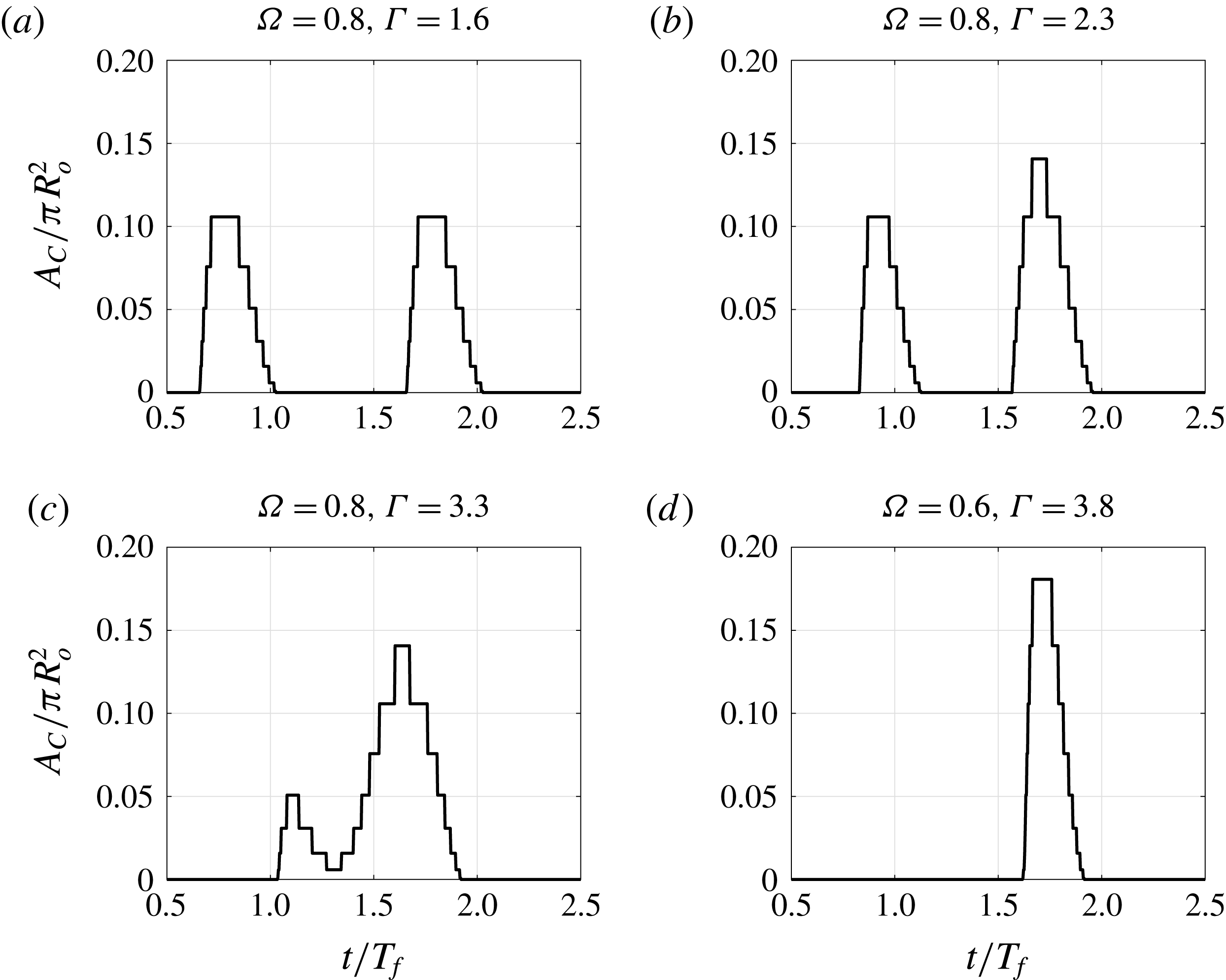


 Open access