

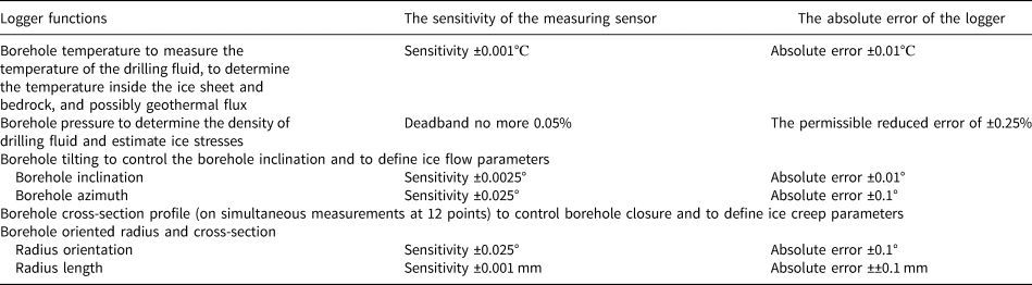
1. Introduction
Borehole logging in the ice sheets and glaciers represents an important source of information about the physical situation in the hole and facilitates two main tasks: (1) to monitor the technical condition of the borehole, and (2) to study ice structure, composition and dynamics for scientific purposes. Conventional geological borehole loggers are hardly suitable for geophysical surveys in glaciers and ice sheets because of unavailability for low-temperature applications and poor measurement accuracy. For this reason, several borehole loggers were designed especially for glaciological investigations (Naruse and others, Reference Naruse, Shimbori, Akitaya and Suzuki1985; Gundestrup and others, Reference Gundestrup, Clausen and Hansen1994; Lefebvre and others, Reference Lefebvre, Augustin and Maitre2002; Clow, Reference Clow2008).
These instruments proved to be quite effective, although they had some serious disadvantages when measuring borehole cross-section profiles. First of all, all of them had three arms to log the shape of the borehole cross-section. This is sufficient to determine the closure rates of boreholes with the implicit assumption that a circular borehole cross-section remains circular. On the other hand, to determine an elliptically shaped borehole and to register the anisotropy factor with a caliper probe, at least five points are necessary for an exact fit of an ellipse. Schwerzmann in 2006 developed an inclinometer–caliper probe with eight arms (Schwerzmann and others, Reference Schwerzmann, Funk and Blatter2006), which was tested in the Fiescherhorn glacier in the Swiss Alps. The eight-arm caliper sounding yields the shape of the cross-section of the borehole – regression circles and ellipses. However, this is only the first obvious hypothesis to be tested and the results presented in this work are not sufficient in all cases to confirm the hypothesis that boreholes can deform elliptically.
Currently, piece-wise borehole loggers based on the use of 3D accelerometers and 3D magnetometers, which are made using MEMS (Micro-Electro-Mechanical Systems) technology, have been specially developed for glacial exploration. These loggers were used to obtain kinematic measurements of streaming ice in Jarvis Glacier, Alaska (Lee and others, Reference Lee2019) and to identify the englacial deformation profile which is determined from borehole tilt measurements on Store Glacier, Greenland (Doyle and others, Reference Doyle2018).
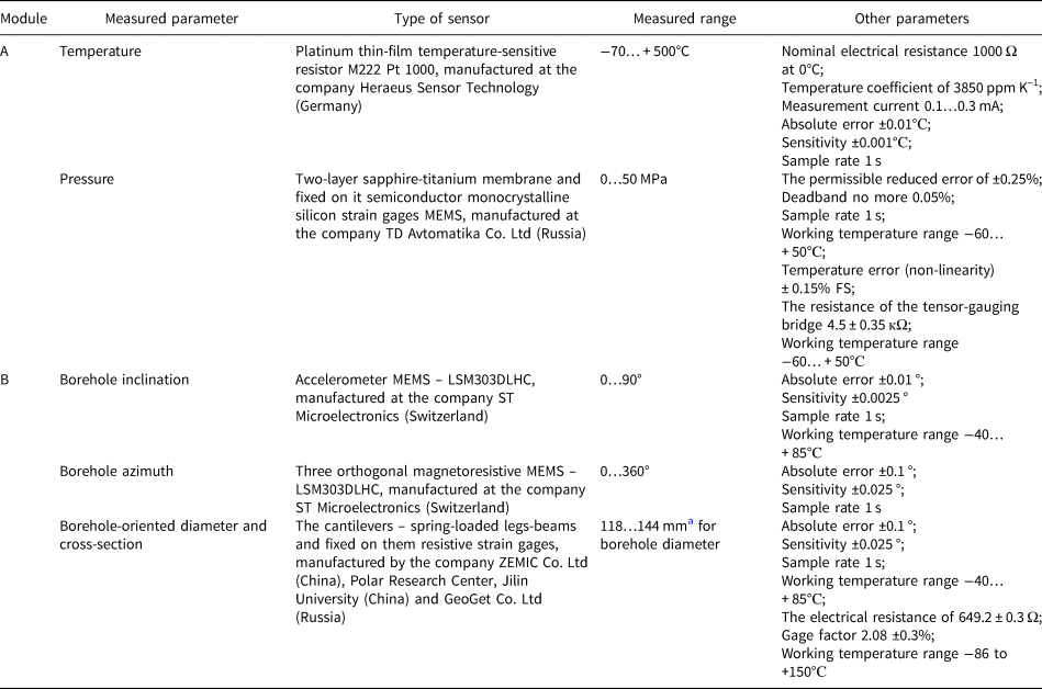
The new borehole logger designed for ultra-low temperatures and ultra-high pressures developed in Polar Research Center, Jilin University, China permits simultaneous measuring of multiple borehole parameters: temperature, pressure, borehole inclination, borehole azimuth, borehole-oriented diameter and cross-section (Table 1).
Sensor's parameters
In this paper, we present the design and results of laboratory and field tests of the new state-of-the-art borehole logger for geophysical surveys in glaciers and ice sheets. We gave a conditional name to the logger ANTTIC – Antarctic Thermo-barometer, Inclinometer, Caliper.
2. General design
The logger includes two modules, which are assembled via a hinged joint: (1) module A, which contains temperature and pressure loggers, and (2) module B, which contains oriented caliper and inclinometer loggers (Table 2). Both modules can work at temperatures down to −60°C and pressures up to 40 MPa. The measured data are digitized, multiplexed and send via the armored cable to the surface computer. Downhole electronic components are installed inside the high-pressure chambers where a special automatic thermally stabilized heater maintains a constant temperature of ~0…+4°C (not lower than −10°C).
Sensor's parameter
a By the terms of reference for measurements of diameter in the borehole at Kun'lun’ station.
2.1. Module A: thermometer and pressure logger
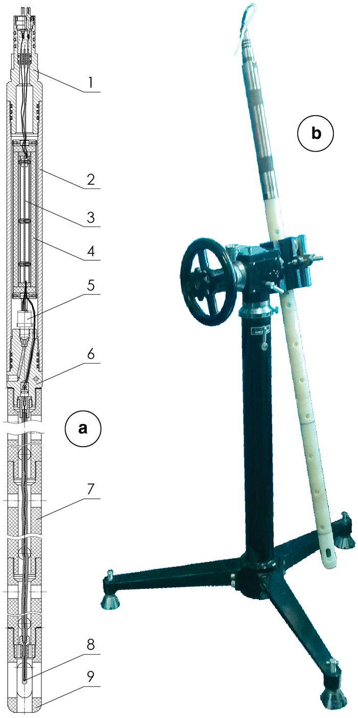
The temperature measurement is recorded by a platinum thin-film temperature-sensitive resistor sensor M222 Pt1000 (Heraeus, 2019) (Fig. 2(1); Table 2) placed inside the guide head at a distance of 1 m away from the body to measure a thermally undisturbed medium and avoid the influence of the heated body (Figs 1 and 2). The optimal distance of 1 m was determined through model and borehole experiments at Vostok station in 2003–2010 by recording (with the second, not heated logger) the propagation of a thermal wave from the body of the heated logger through the drilling fluid to the temperature recorder. The extension tube is produced from Caprolon® (Fig. 2(3)), a material with low thermal conductivity and has openings for better contact with the outside environment (Figs 1(a7) and 2(3)).
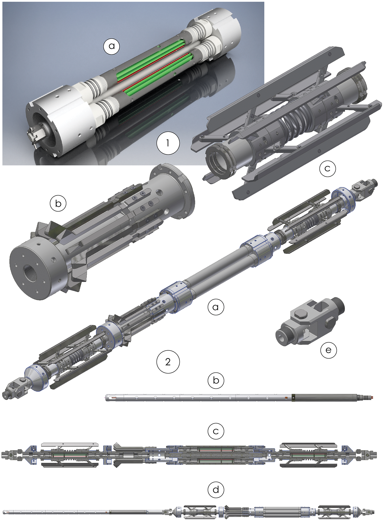
Module A (temperature-pressure logger): (a) general schematic: (1) adapter-tip with electric contacts; (2) high-pressure chamber; (3) electronic components; (4) insulation material; (5) pressure sensor; (6) coupling adapter; (7) low thermal conductivity housing (extension tube from Caprolon®); (8) thermometer; (9) guide head; (b) general view of the logger.
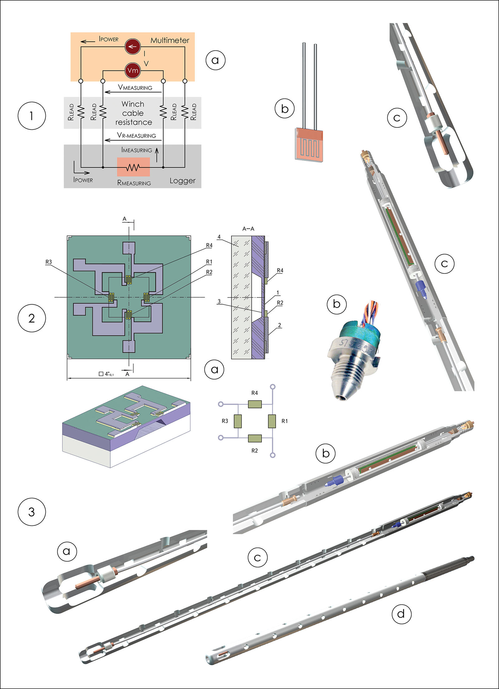
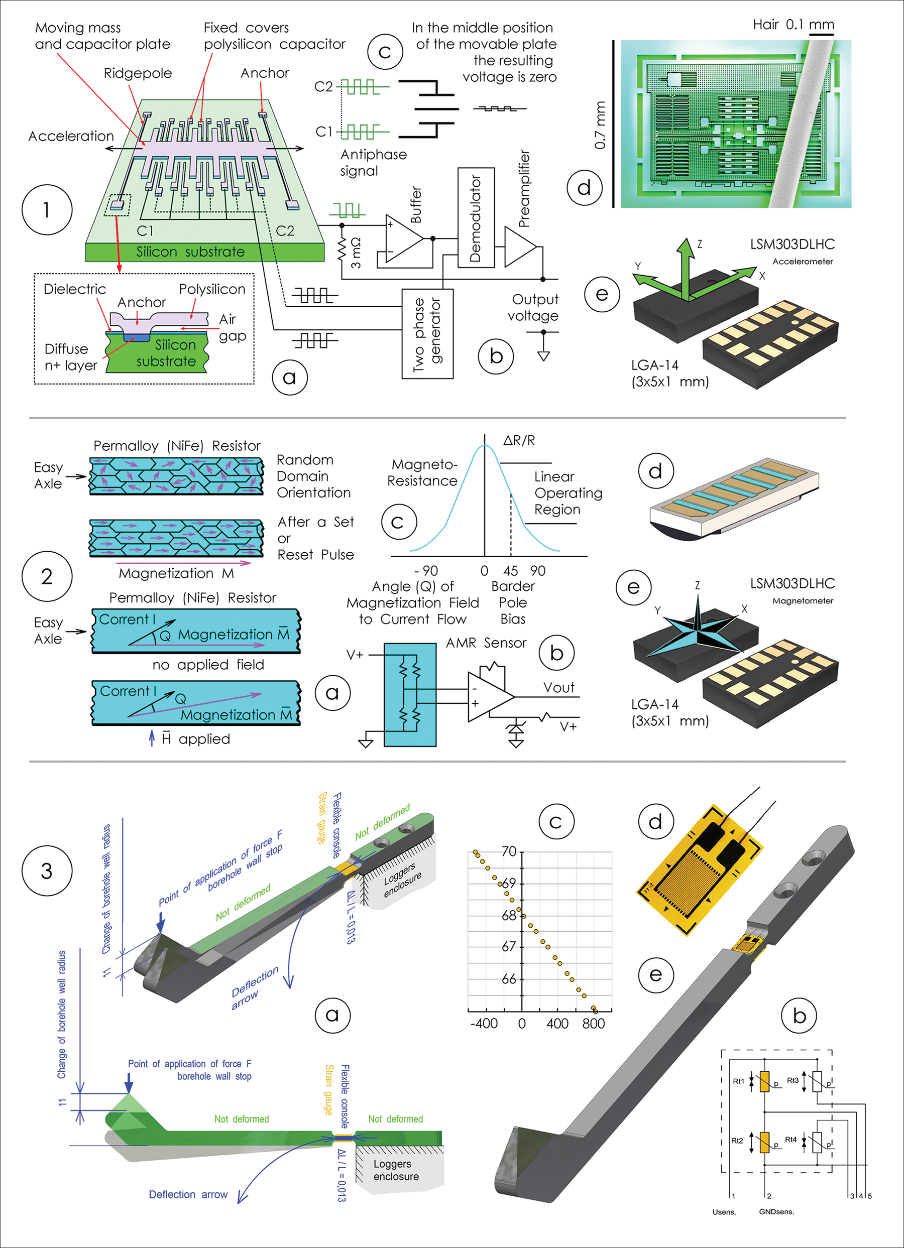
Design solution of the borehole logger: (1) measure the temperature of drilling fluid in the borehole and the temperature of the ice around the borehole: (a) sensor connection diagram (inside the borehole logger) – electrical four-wire; (b) measuring sensor – platinum thin-film temperature-sensitive resistor sensor M222 Pt 1000; (c) part of the housing of the borehole logger (produced from Caprolon®) with a thermometer (in the cross-section); (2) measure the pressure of drilling fluid in the borehole: (a) measurement sensor (scheme): R1; R2; R3; R4 – monocrystalline silicon strain gages; 1, 3 – two-layer sapphire-titanium membrane; 2 – contact; 4 – titanium housing; (b) the pressure measurement sensor manufactured at the company TD Avtomatika Co. Ltd (Russia); (c) part of the housing of the borehole logger with pressure reader and electronic block (in the cross-section); (3) multi-functional temperature and pressure reader of drilling liquid in the borehole: (a) part of the housing of the borehole logger (produced from Caprolon®) with a temperature meter (in the cross-section); (b) part of the housing of the borehole logger with a pressure meter and electronic unit (in the cross-section); (c) comprehensive borehole logger (in the cross-section) with an extension tube length 100 cm produced from Caprolon®; (d) comprehensive borehole logger.
The borehole pressure is applied through the hole in the coupling (Fig. 1(a6)) to the pressure sensor (two-layer sapphire-titanium membrane and monocrystalline silicon resistance strain gauges) (Fig. 2(2)).
2.2. Module B: inclinometer and oriented caliper logger
It is intended to measure the borehole inclination, azimuth and six diameters to determine an elliptical borehole shape and register the anisotropy factor (Figs 3 and 4). It consists of two block-centralizers (six independent spring-loaded skids in each), 12 measuring spring-loaded legs-beams – the cantilevers, four independent high-pressure chambers with electronic components and MEMS measurement sensors: gyroscope; accelerometer (Fig. 4(1)); three orthogonal magnetoresistive sensors (Fig. 4(2)); inside pressure sensor. All electronic MEMS sensors are fixed on one board LSM303DLHC (STMicroelectronics, 2013). Electronic components and MEMS measurement sensors are independent for each high-pressure chamber. Each measuring spring-loaded leg-beam (the cantilever): (1) contains a recession in which two resistance strain gauges are glued (Fig. 4(3)); (2) measures the radius from the axis of the logger to the borehole wall that allows to build up a precise cross-section of the borehole based on 12 simultaneous sample point measurements.
Module B (inclinometer and oriented caliper logger): (a) general schematic: (1) adapter-tip with three electrical contacts; (2) centralizer (six spring-loaded skids); (3) high-pressure chambers (four independent); (4) electronic components; (5) resistance strain gauges (two on each the cantilever (leg-beam)); (6) borehole diameter measurers – the cantilevers – independent spring-loaded legs-beams (12 pieces); (b) general view of the logger.

Design solution of the borehole logger for inclinometer (1, 2) and oriented caliper logger (3): (1) measurer of the zenith (vertical) axis incline angle of the borehole axis – 3D accelerometer LSM303DLHC: (a) measurement principle; (b) sensor connecting diagram – voltage meter; (c) form of a signal measured; (d) sensory element – 3D accelerometer MEMS; (e) measurement sensor – LSM303DLHC; (2) measurer of the azimuth of the direction of the borehole axis – three orthogonal magnetoresistive sensors in LSM303DLHC: (a) measurement principle; (b) sensor connecting diagram – electrical enclosed bridge; (c) form of a signal measured; (d) sensory element – three orthogonal magnetoresistive sensors MEMS; (e) measurement sensor – LSM303DLHC; (3) measurer of the radius of a cross-section of the borehole – the cantilevers – spring-loaded legs-beams and fixed on them resistive strain gages: (a) measurement principle; (b) sensor connecting diagram – electrical enclosed bridge; (c) form of a signal measured; (d) sensory element – resistive strain gages; (e) measurement sensor – the cantilever – spring-loaded leg-beam and fixed on them resistive strain gages.
3. The results of applying and testing
All sensors of the logger are calibrated by comparison of measurements with high-precision measuring devices (Fig. 5; Table 2). Calibration of the logger sensors is performed in the pressure test machine installed into the freezing box.
The results of applying and testing: (1, 2) in deep ice boreholes at the Vostok station in Antarctica: (1) temperature measurements; (2) measuring the pressure of the drilling filling fluid; (3) measure the radius of a cross-section of the borehole: (a) the linear dependence of the electrical resistance of the tensor (in the conventional units of the data transmission code) on changes in the radius of borehole cross-sections along with the entire measurement range; (b) the effect of tensor resistance strain gauges hysteresis during constriction and stretching over the entire measurement range.

The borehole logger module for temperature and pressure measuring (identical prototype to the logger discussed in the article) was systematically used to monitor a deep borehole at Vostok station in Antarctica to a depth of 3700 m (Figs 5(1) and (2)). Based on these temperature and pressure measurements, the following tasks were performed: (1) paleoclimatic reconstructions (Salamatin and others, Reference Salamatin, Vostretsov, Petit, Lipenkov and Barkov1998a, Reference Salamatin1998b); (2) the optimal technical parameters for drilling operations to open Lake Vostok were determined (Lukin, Reference Lukin2011; Lukin and Vasiliev, Reference Lukin and Vasiliev2014); (3) the geothermal heat flux under the ice sheet at Vostok station was estimated (Talalay and others, Reference Talalay2020).
As a result of the analysis of these measurements of thermophysical properties at the base of the Antarctic Ice Sheet at sites of deep ice drilling at Vostok station at a depth of Z = 3759 m, the following data were determined (Talalay and others, Reference Talalay2020):
• The ice temperature is −2.49°С;
• The temperature gradient is 0.0202°С m–1;
• The conductive heat flux is 42.6 ± 0.4 mW m–2.
We carried out individual calibration for each sensor:
(1) The calibration of temperature and pressure meter was performed using high-precision (reference) temperature and pressure gauges in The D.I.Mendeleev All-Russian Institute for Metrology (VNIIM), State Scientific Center of the Russian Federation, State Test and Measurement Instrument Certification Center (https://www.vniim.org/index.html);
(2) The calibration and testing of the cross-sectional profile logger were carried out in laboratory conditions with the use of a high-precision micrometer with an accuracy of 0.001 mm. Based on these results, the following conclusions can be drawn: (1) for resistance strain gauges, there is the absolutely linear ratio of the electrical resistance of the change in the radius of the cross-sections of the borehole over the entire measurement range (Fig. 5(3a)); (2) the influence of resistance strain gauges hysteresis during constriction and stretching over the entire measurement range is within the errors of 0.01 mm (Fig. 5(3b));
(3) The calibration and the testing of the inclinometer were carried out according to the method developed by us. This technique is similar to the calibration system of angle and azimuth sensors, which is offered by the company manufacturer STMicroelectronics (Vitali, Reference Vitali2021).
Based on the calibration results, the corresponding coefficients were entered for all measurements, for all sensors.
All sensors are rigidly attached to the logger housing (utilizing a rigid fixing measuring sensor to a common electronic circuit board in a hard metal beaker which is rigidly attached to the common metal body of the logger in the high-pressure chamber) (Fig. 6(1a)). All parts of the logger are made of non-magnetic metal (brass, aluminum, stainless steel).
Construction solution of the comprehensive borehole meter: (1) logger parts: (a) electrical units (four-time duplication) (without hermetic housing); (b) borehole cross-section radius meter in 12 directions (12 measuring cantilever); (c) device for centering the borehole logger along the borehole axis; (2) borehole logger versions: (a) inclinometer and measure the cross-section of the borehole (caliper log); (b) сomprehensive temperature and pressure reader of drilling liquid in the borehole; (c) inclinometer and measure the cross-section of the borehole (caliper log) (sectional drawing); (d) comprehensive borehole logger: inclinometer and measure the cross-section of the borehole (caliper log) together with сomprehensive temperature and pressure reader of drilling liquid in the borehole; (e) swivel joint.
All high-precision calibration was carried out for the entire assembled logger. Thus, the total measurement error was determined: primary error of sensors + error of fixing sensors to the logger body.
The centering device (Fig. 6(1c)) has identical precision in the manufacture of parts; the identical pressing force against the borehole walls and the identical mechanics (backlash, the angle of inclination of the levers, etc.) in six radially symmetric directions. Thus, the centering of the logger axis along the borehole axis is achieved.
4. Discussion and conclusion
4.1. Some aspects of the observation correctness
The horizontal plane is not preferred for displaying the cross-section of the borehole. For the scientific study of the ellipsoid of the borehole compression, whose shape is related to glacier dynamics or anisotropy, in our opinion, the preferential plane for constructing the cross-section of the borehole is the plane of inclination for the ice layer under study. This plane of the ice layer is not necessarily horizontal; its inclination can be individual for each glacier and depth of study (Fig. 7(1)). This is especially true for glaciers and subglacial mountainous regions in ice sheets (which include the region for a borehole at Kun'lun’ station on the dome ‘A’, over the Gamburtsev subglacial mountains). Therefore, for correct analysis (recalculation of the cross-section into the desired plane), it is necessary to have radar profiling data on the structure of the ice sheet and the slope of the ice layer under study.
(1) The principle of calculating the coordinates of the projection of a circle on an arbitrary plane α: α' – the plane is orthogonal to the axis of the borehole (in this plane the radius R and the borehole profile k are measured); β – (the angle between the planes α and α') this can be either the measured inclination of the borehole (in this case, the plane α is horizontal) or the measured inclination of the borehole plus the angle of inclination of the ice layer (in this case, the plane α' coincides with the plane of the studied ice layer); rot is the logger rotation angle around its axis plus the sector angle for each cantilever (individual for each of the 12 cantilever in a circle, in the range from 0 to 360° with a step of 30°). (2) Evaluation of the sector of the error in the coordinates of the borehole profile point recorded by the cantilever: I – the point inclinometer; C – the point cantilever; L = 516 mm – the distance from the cantilever point to the inclinometer point; δβ = 0.01° – absolute measurement error for borehole inclination; δXβ = 0.09 mm – absolute error in determining the X coordinate for the cantilever point, which depends on δβ and L; δXcant = 0.01 mm – absolute error of the cantilever meter; δXcant + δXβ = 0.1 mm – total absolute error in determining the X coordinate for the cantilever point, which depends on δβ, L and δXcant; δZβ = 1.212 × 10⁻⁶ – is the absolute error in determining the X coordinate for the cantilever point, which depends on δβ and the measured borehole radius R (maximum R = 144 mm); δrot = 0.1° – absolute error in measuring the angle of rotation of the logger around its axis; δYrot = 0.251 mm – absolute error in determining the X coordinate for the cantilever point, which depends on δrot and the measured borehole radius R (maximum R = 144 mm).

The error in determining the coordinates (x, y, z) of the perimeter of the borehole cross-section depends on (Fig. 7(2)): the sensors errors; the logger design – distance from the point of the inclinometer sensor to the point of the cantilever contact (for our logger, this turned out to be the main influence); the borehole radius.
It should be noted that the absolute errors of the cantilever (and the logger as a whole) when monitoring at a fixed point of contact of the cantilever with the borehole wall (when determining the coordinates of the point (x, y, z) (Fig. 7(2))), do not matter, because there is the magnitude of the temporal gradient of these coordinates in the foreground. Since when calculating the temporal gradients at a fixed point (grad(x), grad(y), grad(z)), the absolute errors of registration of coordinates of this point (δx, δy, δz) are canceled; therefore, the main factor for the high accuracy of recording the ellipsoidal change in the borehole cross-section is the minimum discreteness of measuring the radius dis(r) (for our logger dis(r) = 0.001 mm (the sensitivity of cantilever)).
However, when carrying out measurements in a deep ice borehole at Vostok station, we faced the following real problems:
– The influence of cosmic magnetic storms on the readings of the magnetic inclinometer (near the magnetic pole of the Earth);
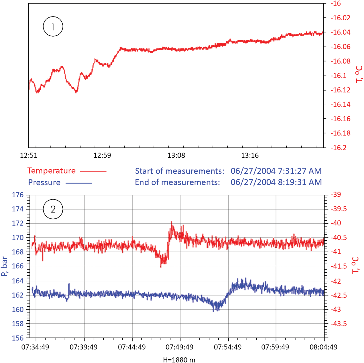
– The influence of the borehole fluid flows (convective and/or accompanying the movement of the borehole logger) on the temperature and pressure measurements (Fig. 8(1));
– The effect of different changing thermal elongation of the carrying cable at different speeds of descent on the accuracy of determining the measuring point depth which is especially important for monitoring;
– The influence on the misalignment of the logger axis and the borehole axis is imposed by the ‘clamping force’ of the cable to the borehole wall – the effect of uncentered cable (due to the inclination or curvature of the borehole, bending of the cable, the fastening massive cable to a light logger…);
– The influence of tidal gravitational forces on the readings of the accelerometer, borehole vertical angle meter;
– The effect of changes in the external atmospheric pressure on the pressure and temperature measurements in the borehole fluid (Fig. 8(2));
– The effect of ice hardness on the borehole walls on the correctness of the borehole diameter measurement;
– The influence of snow electric charges on the stability of the communication line in the absence of grounding, the ratio of the length of cable on the winch and in the borehole changes the parameters in inductive and capacitive resistances for registration system (cable on the winch and in the borehole – antenna effect).
(1) The changes in the temperature of the drilling fluid (in the borehole 5G-2 at Vostok station after the descent at a depth of 3100 m, during 40 min of measurements), that are caused by the influence of the borehole fluid flows (convective and/or accompanying the movement of the borehole logger). (2) Depressurization wave. The drilling complex 3-G at Vostok station was in a pressurized state during the night (12 h) (on 26-27.06.2004). The conditions for sealing the drilling complex 3-G: covered with snow above the roof; there are no people at night. Temperature conditions: –74°С – external (on the street); –31°С in the entrance airlock (heated) compartment; –41°С in the corridor between the compartments airlock – borehole2; –53°С in the compartment of the borehole 3-G; –57°С at the borehole head of the borehole 3-G. The thermometer and pressure logger were kept for 12 h (during the sealed state of the drilling complex) at a depth of 1880 m. The level of the borehole fluid is at a depth of 92 m. When the drilling complex was depressurized (opening-closing the front door), the logger recorded a wave change (increase-decrease-return to the previous level) in the borehole at a depth of 1880 m: The temperature wave after ~13 min, propagation velocity in borehole 2.41 m s–1, the fluctuation amplitude ±0.5°С, wave period ~10 min; the pressure wave after 18 min, propagation velocity in borehole 1.74 m s–1, the fluctuation amplitude ±2 bar, wave period ~10 min. So far, only one thing can be said about such paradoxes – the borehole is not at all indifferent to the thermobaric processes that occur on the surface (in the drilling complex).
All these problems, to one degree or another, require further deep comprehensive study to eliminate their influence.
4.2. Some aspects of using the logger
Drilling and studying deep ice boreholes in Antarctica and Greenland is a unique process in which each borehole has individual technical solutions (Talalay, Reference Talalay2016) and the parameters of the ice sheet around each borehole are also unique.
The conclusion can be drawn that, for borehole loggers that are designed for taking measurements in deep ice boreholes in Antarctica and Greenland, the following construction solutions can be effective:
(1) Applying Microelectromechanical Systems (MEMS) for sensors:
– Measure the pressure of drilling fluid in the borehole;
– Inclinometer:
– Measure the zenith (vertical) axis incline angle of the borehole axis (3D accelerometer);
– Measure the azimuth of the direction of the borehole axis (3D magnetometer);
– Measure the angle of rotation of the borehole logger around the axis of the borehole (for orienting the borehole cross-section radii measurements) (3D magnetometer);
(2) The design of a cantilever and strain gauge for measuring the radius of the borehole cross-section;
(3) The device for measuring electrical resistance at various sensors and encoding an analog signal to digital.
The accuracy and especially sensitivity of measurement systems based on the applied construction solutions allow, besides the fulfillment of the technical objectives of monitoring the condition of the borehole, to also attain the required highly-accurate measurements to accomplish real scientific objectives (Bons and others, Reference Bons2016; Markov and others, Reference Markov2016; Dahl-Jensen and others, Reference Dahl-Jensen, Vinther, Larsen, Sheldon and Steffensen2017), for registration the following parameters and phenomena:
– Temperature characteristics of the ice sheet;
– The Earth's heat flow in the borehole area;
– The structure of the ice-sheet current (based on the results of highly-accurate monitoring of changes in the direction of the borehole's axis (inclinometry));
– The anisotropic mechanical properties of ice around the borehole (based on the results of highly-accurate monitoring of the changing radius of the borehole cross-section).
The logger presented in the article was manufactured for operation on specific boreholes in Antarctica. We did not strive to create a universal logger for all boreholes in the world. However, we hope that the solutions incorporated in the ANTTIC logger can be universally useful in a wide range of logger applications. With insignificant design changes based on the ANTTIC logger, it is possible to manufacture loggers for boreholes with other operating conditions.
In our opinion:
– For each specific ice borehole (for physical parameters of ice and operating conditions on this borehole), an individual unique logger should be made;
– Unique logger would make it possible to provide unique high precision measurements to solve scientific problems.


 Open access