


1. Introduction
Rod-like particle suspensions are ubiquitous in nature and have diverse industrial applications (Solomon & Spicer Reference Solomon and Spicer2010). These small, elongated particles play a significant role in various complex phenomena, ranging from the microscopic to the macroscopic scales. For instance, in three-dimensional (3-D) printing, cellulose nanocrystal inks utilize these particles as building blocks for macroscale bulk materials (Hausmann et al. Reference Hausmann, Ruhs, Siqueira, Läuger, Libanori, Zimmermann and Studart2018). Additionally, researchers have explored their potential for transporting microcargo within narrow channels, offering promising possibilities for targeted drug delivery systems (Yang & Bevan Reference Yang and Bevan2018; Yang et al. Reference Yang, Zhu, Liu, Wang, Li, Marchesoni, Hänggi and Zhang2019). Beyond these specific examples, rod-like particles find further applications in composite processes owing to their responsiveness to external fields, making them valuable functional materials within these composites (De Vicente, Klingenberg & Hidalgo-Alvarez Reference De Vicente, Klingenberg and Hidalgo-Alvarez2011; Pignon et al. Reference Pignon, Semeraro, Chèvremont, Bodiguel, Hengl, Karrouch and Sztucki2021; Kuznetsov et al. Reference Kuznetsov, Kovaleva, Belousov and Chvalun2022). The paper production industry utilizes short fibres, which are another form of rod-like particles, as key components of the manufacturing process (Lundell, Söderberg & Alfredsson Reference Lundell, Söderberg and Alfredsson2011).
Given their prevalence and diverse functionalities, understanding the behaviour of rod-like particles in shear flow fields is crucial for various scientific and technological advancements. Pioneering work by Jeffery described the motion of a non-Brownian ellipsoidal particle in an unbounded linear shear flow at zero Reynolds number (Jeffery Reference Jeffery1922). This study demonstrates that a particle’s orientational dynamics follows a set of periodic orbits, with the period depending on the aspect ratio of the particle. Jeffery’s solution determines a particle’s specific orbit based on its initial orientation using an orbit constant. However, this solution predicts non-physical behaviour near solid boundaries.
Although several studies have reported the limited effects of walls on the rheology of dilute suspensions of rod-like particles (Petrie Reference Petrie1999; Moses, Advani & Reinhardt Reference Moses, Advani and Reinhardt2001; Zurita-Gotor, Bławzdziewicz & Wajnryb Reference Zurita-Gotor, Bławzdziewicz and Wajnryb2007; Park & Butler Reference Park and Butler2009), investigating particle motion due to rod–wall interactions in planar shear flows remains an interesting subject. Various experiments (Stover & Cohen Reference Stover and Cohen1990; Moses et al. Reference Moses, Advani and Reinhardt2001; Kaya & Koser Reference Kaya and Koser2009) and numerical approaches (Ingber & Mondy Reference Ingber and Mondy1994; Mody & King Reference Mody and King2005) have explored the effects of walls on particle motion, revealing the limited validity of Jeffery’s theory near walls. The wall induces additional resistance to the rotation of the particles, leading to longer rotation periods. However, this effect had minimal impact on the overall rotational behaviour. The primary influence of walls on particle motion may arise from the direct physical contact between the particles and the wall. This interaction can be determined geometrically based on the length of the particle and its distance from the wall. The Jeffery solution, a theoretical framework for describing particle motion in unbounded shear flows, can be incorporated with wall constraints to account for the direct impact of walls on particle trajectories (Ozolins & Strautins Reference Ozolins and Strautins2014; Perez et al. Reference Perez, Scheuer, Abisset-Chavanne, Chinesta and Keunings2016), while neglecting the hydrodynamic interactions between the particle and the wall.
However, microfluidic experiments have revealed three significant results that deviate qualitatively from the predictions of geometric confinement models.
First, when particles undergo tumbling motion near a wall, they can exhibit a ‘pole-vaulting’ motion (Stover & Cohen Reference Stover and Cohen1990; Moses et al. Reference Moses, Advani and Reinhardt2001; Mody & King Reference Mody and King2005; Zurita-Gotor et al. Reference Zurita-Gotor, Bławzdziewicz and Wajnryb2007; Park & Butler Reference Park and Butler2009), where they use the wall as a springboard to propel themselves away from it. This behaviour can lead to a macroscopically observed decrease in particle concentration near the wall compared to that in the bulk suspension.
Second, particles oriented parallel to the wall exhibit quite different behaviours near the wall. Unlike their high-orbit counterparts, these particles maintain a relatively constant separation distance from the wall while still being advected by the flow (Stover & Cohen Reference Stover and Cohen1990). Experimental studies analysing the projected images of these particles on the flow–vorticity plane suggest a periodic oscillatory motion along the axis of flow direction on the plane parallel to the wall, referred to as ‘swinging motion’ (Kaya & Koser Reference Kaya and Koser2009; Zöttl et al. Reference Zöttl, Klop, Balin, Gao, Yeomans and Aarts2019). However, this behaviour may be specific to pressure-driven shear flows. In wall-driven shear flows investigated by other studies, particles tend to align with the flow direction and remain in this orientation without exhibiting periodic motion (Moses et al. Reference Moses, Advani and Reinhardt2001; Hijazi et al. Reference Hijazi, Yahia, Khater and Zoaeter2003).
Third, another noteworthy aspect is the behaviour of weakly sedimented fibres under inclined liquid film flows. Near the wall, these fibres tend to orient themselves perpendicularly to the flow direction, exhibiting a ‘rolling-sliding motion’ as they move down the inclined plate (Carlsson, Lundell & Söderberg Reference Carlsson, Lundell and Söderberg2007; Holm & Söderberg Reference Holm and Söderberg2007; Carlsson Reference Carlsson2009). This perpendicular orientation diminishes as the distance from the wall increases, with fibres retaining their initial orbit constants. These tendencies are likely to influence the concentration of fibres near the wall, although detailed results regarding this aspect remain inconclusive (Lundell et al. Reference Lundell, Söderberg and Alfredsson2011).
In this study, we present the results of a numerical investigation into the orientational dynamics of rod-like particles near walls under two types of shear flows, Couette flow (C-flow) and Poiseuille flow (P-flow), at negligibly small inertia. This research aims to characterize how particle–wall interactions under shear flows influence a particle’s orientational dynamics and trajectory. The influence of flow conditions on these interactions will be studied systematically. The model of a rod-like particle, represented by a chain of hard spheres, and the hydrodynamics of the particle immersed in a liquid, are described in § 2. The suspending liquid was simulated using the lattice Boltzmann (LB) method. The simulation results are presented in § 3. Section 3.1 provides a detailed explanation of how the Jeffery orbits, which are modified by interactions with the wall, change with the separation distance in different shear flows. In § 3.2, we describe the effect of mechanical contact on the pole-vaulting motion of particles with tumbling motions. Additionally, we present the trajectory changes of weakly sedimenting single particles towards the wall, along with the corresponding orientation distribution at a dilute concentration for each flow in § 3.3.
2. Model and simulation method
2.1. Classical Jeffery model
Jeffery (Reference Jeffery1922) analysed the motion of a single ellipsoidal particle in a uniform, unidirectional viscous flow field. The particles were translated by the local fluid velocity, and their orientation changes were determined by the rates of strain and rotation. Specifically, when the rigid ellipsoidal particle is placed in a linear flow composed of a symmetric strain rate
 $\boldsymbol {e}^\infty ={1}/{2}(\nabla \boldsymbol {u}^\infty +(\nabla \boldsymbol {u}^\infty )^{\mathrm {T}})$
and an antisymmetric rotation rate
$\boldsymbol {e}^\infty ={1}/{2}(\nabla \boldsymbol {u}^\infty +(\nabla \boldsymbol {u}^\infty )^{\mathrm {T}})$
and an antisymmetric rotation rate
 $\boldsymbol {w}^\infty ={1}/{2}(\nabla \boldsymbol {u}^\infty -(\nabla \boldsymbol {u}^\infty )^{\mathrm {T}})$
, the equation for the orientation vector
$\boldsymbol {w}^\infty ={1}/{2}(\nabla \boldsymbol {u}^\infty -(\nabla \boldsymbol {u}^\infty )^{\mathrm {T}})$
, the equation for the orientation vector
 $\boldsymbol {p}=(p_x,p_y,p_z)$
of the particle, illustrated in figure 1, is described in Guazzelli & Morris (Reference Guazzelli and Morris2011) as
$\boldsymbol {p}=(p_x,p_y,p_z)$
of the particle, illustrated in figure 1, is described in Guazzelli & Morris (Reference Guazzelli and Morris2011) as
 \begin{equation} \frac {d\boldsymbol {p}}{dt}=\boldsymbol {w}^\infty \cdot \boldsymbol {p}+\frac {A^2-1}{A^2+1}\left [\boldsymbol {e}^\infty \cdot \boldsymbol {p}-\boldsymbol {p}\left (\boldsymbol {p}\cdot \boldsymbol {e}^\infty \cdot \boldsymbol {p}\right )\right ], \end{equation}
where the superscript
 $\infty$
refers to an undisturbed flow of pure liquid. Here,
$\infty$
refers to an undisturbed flow of pure liquid. Here,
 $A$
is the aspect ratio
$A$
is the aspect ratio
 $L/d$
,
$L/d$
,
 $d$
is the particle diameter, and
$d$
is the particle diameter, and
 $L$
is the particle length. Under uniform shear flow with a constant shear rate
$L$
is the particle length. Under uniform shear flow with a constant shear rate
 $\dot {\gamma }$
described by
$\dot {\gamma }$
described by
 $\boldsymbol {u}^\infty =\dot {\gamma } y\hat {\boldsymbol {x}}$
, (2.1) can be integrated and written as
$\boldsymbol {u}^\infty =\dot {\gamma } y\hat {\boldsymbol {x}}$
, (2.1) can be integrated and written as
 \begin{equation} \boldsymbol {p}=\frac {1}{\sqrt {A^2\sin ^2(\omega t+\kappa )+\cos ^2(\omega t+\kappa )+1/C_J^2}} \begin{bmatrix} A\sin (\omega t+\kappa )\\ \cos (\omega t+\kappa )\\ 1/C_J \end{bmatrix}, \end{equation}
where the motion becomes periodic with period
 $T_J=2\pi (A+A^{-1})/\dot {\gamma }$
with angular frequency
$T_J=2\pi (A+A^{-1})/\dot {\gamma }$
with angular frequency
 $\omega =2\pi /T_J$
, and the hat symbol denotes the unit vector along each vector, throughout the paper. The two integration constants
$\omega =2\pi /T_J$
, and the hat symbol denotes the unit vector along each vector, throughout the paper. The two integration constants
 $C_J$
(known as the orbit constant) and
$C_J$
(known as the orbit constant) and
 $\kappa$
(known as the phase angle) are determined from the initial orientation of particle as
$\kappa$
(known as the phase angle) are determined from the initial orientation of particle as
 $C_J=\sqrt {(p_x^0/A)^2+(p_y^0)^2}\big /p_z^0$
and
$C_J=\sqrt {(p_x^0/A)^2+(p_y^0)^2}\big /p_z^0$
and
 $\kappa =\tan ^{-1} (p_x^0/(Ap_y^0) )$
, where the superscript 0 denotes the initial value throughout the paper. The orbit constant varies between 0 and
$\kappa =\tan ^{-1} (p_x^0/(Ap_y^0) )$
, where the superscript 0 denotes the initial value throughout the paper. The orbit constant varies between 0 and
 $\infty$
. In the special case at
$\infty$
. In the special case at
 $C_J=0$
, the ellipsoid is always aligned along the vorticity axis (log-rolling). In the other special case, at
$C_J=0$
, the ellipsoid is always aligned along the vorticity axis (log-rolling). In the other special case, at
 $C_J=\infty$
, the ellipsoid rotates in the
$C_J=\infty$
, the ellipsoid rotates in the
 $xy$
-plane with two-dimensional (2-D) planar motion (tumbling). In between, the ellipsoid moves along closed orbits around the vorticity axis (kayaking). The trajectories of the particles with representative orbit constants are plotted in Appendix A.
$xy$
-plane with two-dimensional (2-D) planar motion (tumbling). In between, the ellipsoid moves along closed orbits around the vorticity axis (kayaking). The trajectories of the particles with representative orbit constants are plotted in Appendix A.
(a) Coordinate system used to simulate a rod-like particle. The particle is modelled by a linear chain of beads of diameter
 $d$
and length
$d$
and length
 $L$
. The chain orientation is characterized by a body-centred coordinate system with the orientation vector
$L$
. The chain orientation is characterized by a body-centred coordinate system with the orientation vector
 $\boldsymbol {p}$
. In the angular form, one of the polar angles,
$\boldsymbol {p}$
. In the angular form, one of the polar angles,
 $\phi$
, denotes the angle between the
$\phi$
, denotes the angle between the
 $y$
-axis and the orthogonal projection of the particle on the
$y$
-axis and the orthogonal projection of the particle on the
 $xy$
-plane, while the other angle,
$xy$
-plane, while the other angle,
 $\theta$
, denotes the angle between the
$\theta$
, denotes the angle between the
 $z$
-axis and the particle. A bead
$z$
-axis and the particle. A bead
 $m$
is separated by a small surface-to-surface distance
$m$
is separated by a small surface-to-surface distance
 $\epsilon d$
from the neighbouring beads, and
$\epsilon d$
from the neighbouring beads, and
 $\boldsymbol {t}_m$
is the tangent vector from the (
$\boldsymbol {t}_m$
is the tangent vector from the (
 $m-1$
)th bead to the
$m-1$
)th bead to the
 $m$
th bead. The orientation vector
$m$
th bead. The orientation vector
 $\boldsymbol {p}_m$
of bead
$\boldsymbol {p}_m$
of bead
 $m$
aligns with the orientational vector
$m$
aligns with the orientational vector
 $\boldsymbol {p}$
of the particle at angle
$\boldsymbol {p}$
of the particle at angle
 $\theta _m$
. (b) Schematic of a periodic box with height
$\theta _m$
. (b) Schematic of a periodic box with height
 $H$
for simulating planar shear flows. The velocity field within the box, unaffected by particles, is denoted by
$H$
for simulating planar shear flows. The velocity field within the box, unaffected by particles, is denoted by
 $\boldsymbol {u}^\infty$
. Each shear flow is generated by the lower and upper walls moving at the same speed,
$\boldsymbol {u}^\infty$
. Each shear flow is generated by the lower and upper walls moving at the same speed,
 $u_w/2$
, in the opposite directions for C-flow, and by applying an external force density
$u_w/2$
, in the opposite directions for C-flow, and by applying an external force density
 $\boldsymbol {F}^{ext}$
in the positive
$\boldsymbol {F}^{ext}$
in the positive
 $x$
-direction for P-flow.
$x$
-direction for P-flow.

Equation (2.1) can be rewritten in angular form using the spherical coordinate system’s polar angles
 $\theta$
and
$\theta$
and
 $\phi$
(Stover & Cohen Reference Stover and Cohen1990; Guazzelli & Morris Reference Guazzelli and Morris2011), defined as
$\phi$
(Stover & Cohen Reference Stover and Cohen1990; Guazzelli & Morris Reference Guazzelli and Morris2011), defined as
 $p_x=\sin \theta \sin \phi$
,
$p_x=\sin \theta \sin \phi$
,
 $p_y=\sin \theta \cos \phi$
and
$p_y=\sin \theta \cos \phi$
and
 $p_z=\cos \theta$
as illustrated in figure 1(a):
$p_z=\cos \theta$
as illustrated in figure 1(a):
 \begin{align} \dot {\theta }&=\frac {\dot {\gamma }(A^2-1)}{4(A^2+1)}\sin 2\theta \sin 2\phi , \end{align}
 \begin{align} \dot {\phi }&=\frac {\dot {\gamma }}{A^2+1}(\sin ^2\phi +A^2\cos ^2\phi ). \end{align}
The integration of (2.3a ) and (2.3b ) leads to
 \begin{align} \tan \theta &=\frac {AC_J}{\sqrt {\sin ^2\phi +A^2\cos ^2\phi }}, \end{align}
 \begin{align} \tan \phi &=A\tan \left (\omega t+\kappa \right ), \end{align}
respectively. The solutions obtained here, (2.4a) and (2.4b
), are identical to the previously derived (2.2), with
 $C_J=({1}/{A})\tan \theta ^0\sqrt {\sin ^2\phi ^0+A^2\cos ^2\phi ^0}$
and
$C_J=({1}/{A})\tan \theta ^0\sqrt {\sin ^2\phi ^0+A^2\cos ^2\phi ^0}$
and
 $\tan \kappa =({1}/{A})\tan \phi ^0$
.
$\tan \kappa =({1}/{A})\tan \phi ^0$
.
2.2. Equations of motion for the chain-of-spheres model
To investigate the orientational behaviour of rod-like particles in confined flows computationally, we present a coarse-grained model effective for dynamic simulations. The model involves a particle with fore-and-aft symmetry suspended in a Newtonian liquid within a planar channel. The suspending liquid is explicitly modelled using the LB method.
To model the motion of a rod-like particle in planar shear flows, we discretize it into a chain of non-overlapping, hard spheres, so-called ‘beads’. The overall motion of the particle is approximated using the collective motion of individual beads. As shown schematically in figure 1(a), there are
 $N_b$
beads with diameter
$N_b$
beads with diameter
 $d$
connected with a small surface-to-surface distance
$d$
connected with a small surface-to-surface distance
 $\epsilon d$
(where
$\epsilon d$
(where
 $\epsilon =0.02$
). Each bead has the same mass (
$\epsilon =0.02$
). Each bead has the same mass (
 $M_m$
) and moment of inertia (
$M_m$
) and moment of inertia (
 $I_m$
). This motion is described by Newton’s equations of motion, which include their translational velocity (
$I_m$
). This motion is described by Newton’s equations of motion, which include their translational velocity (
 $\boldsymbol {u}_m$
) and angular velocity (
$\boldsymbol {u}_m$
) and angular velocity (
 $\boldsymbol {\omega }_m$
) as follows:
$\boldsymbol {\omega }_m$
) as follows:
 \begin{equation} M_m\frac {{\mathrm{d}}\boldsymbol {u}_m}{{\mathrm{d}}t}=\boldsymbol {F}_{m}^S+\boldsymbol {F}_{m}^B+\boldsymbol {F}_{m}^R+\boldsymbol {F}_{m}^H, \end{equation}
 \begin{equation} I_m\frac {{\mathrm{d}}\boldsymbol {\omega }_m}{{\mathrm{d}}t}=\boldsymbol {T}_{m}^R+\boldsymbol {T}_{m}^H, \end{equation}
where subscript
 $m$
represents each bead in the particle, ranging from 1 to
$m$
represents each bead in the particle, ranging from 1 to
 $N_b$
. If an external force is present, then it is added to the total force acting on each bead.
$N_b$
. If an external force is present, then it is added to the total force acting on each bead.
For the rod-like particles, the individual beads were assumed to maintain a nearly constant separation distance. Any small deviations from the equilibrium distance
 $l_0=(1+\epsilon )d$
are modelled using Hooke’s law. The stretching energy can be expressed as
$l_0=(1+\epsilon )d$
are modelled using Hooke’s law. The stretching energy can be expressed as
 \begin{equation} U_S=\frac {K_S}{2}\sum _{m=2}^{N_b}(l_m-l_0)^2, \end{equation}
where
 $l_m=|\boldsymbol {t}_m|$
is the length of tangent vector
$l_m=|\boldsymbol {t}_m|$
is the length of tangent vector
 $\boldsymbol {t}_m$
that connects the centre of the
$\boldsymbol {t}_m$
that connects the centre of the
 $(m-1)$
th bead in the
$(m-1)$
th bead in the
 $\boldsymbol {r}_{m-1}$
position to that of
$\boldsymbol {r}_{m-1}$
position to that of
 $m$
th bead in the
$m$
th bead in the
 $\boldsymbol {r}_{m}$
position. The stretching coefficient is represented as
$\boldsymbol {r}_{m}$
position. The stretching coefficient is represented as
 $K_S=\pi Ed/4$
, where
$K_S=\pi Ed/4$
, where
 $E$
is Young’s modulus (Yamamoto & Matsuoka Reference Yamamoto and Matsuoka1993).
$E$
is Young’s modulus (Yamamoto & Matsuoka Reference Yamamoto and Matsuoka1993).
To account for the particle stiffness, the bending energy
 $U_B$
is defined with a discrete element of
$U_B$
is defined with a discrete element of
 $\boldsymbol {t}_m$
as given by Gauger & Stark (Reference Gauger and Stark2006),
$\boldsymbol {t}_m$
as given by Gauger & Stark (Reference Gauger and Stark2006),
 \begin{equation} U_B=K_B\sum _{m=2}^{N_b-1}(1-\hat {\boldsymbol {t}}_{m+1}\cdot \hat {\boldsymbol {t}}_m), \end{equation}
where the bending coefficient is represented as
 $K_B=\pi Ed^3/64$
(Yamamoto & Matsuoka Reference Yamamoto and Matsuoka1993; Haeri, Knox & Ahmadi Reference Haeri, Knox and Ahmadi2013). The stretching and bending forces acting on the
$K_B=\pi Ed^3/64$
(Yamamoto & Matsuoka Reference Yamamoto and Matsuoka1993; Haeri, Knox & Ahmadi Reference Haeri, Knox and Ahmadi2013). The stretching and bending forces acting on the
 $m$
th bead are
$m$
th bead are
 $\boldsymbol {F}_m^S=-\nabla _{r_m}U_S$
and
$\boldsymbol {F}_m^S=-\nabla _{r_m}U_S$
and
 $\boldsymbol {F}_m^B=-\nabla _{r_m}U_B$
, respectively. The resulting stiff chain of beads has
$\boldsymbol {F}_m^B=-\nabla _{r_m}U_B$
, respectively. The resulting stiff chain of beads has
 $A=N_b+(N_b-1)\epsilon$
or the equilibrium length
$A=N_b+(N_b-1)\epsilon$
or the equilibrium length
 $L=Ad$
.
$L=Ad$
.
The rotational constraint force
 $\boldsymbol {F}^R_m$
is associated with the torque applied to maintain the long axes of the particles aligned with the desired orientation. To restrict the rotation of the bead towards the long axis of the particle, a rotational constraint was implemented. This constraint was achieved by applying a rolling torque that acted in the opposite direction to any perpendicular rolling motion of the bead:
$\boldsymbol {F}^R_m$
is associated with the torque applied to maintain the long axes of the particles aligned with the desired orientation. To restrict the rotation of the bead towards the long axis of the particle, a rotational constraint was implemented. This constraint was achieved by applying a rolling torque that acted in the opposite direction to any perpendicular rolling motion of the bead:
 \begin{equation} \boldsymbol {T}_m^R=-K_R\theta _m\frac {\boldsymbol {p}\times \boldsymbol {p}_m}{|\boldsymbol {p}\times \boldsymbol {p}_m|}, \end{equation}
where
 $\theta _m=\cos ^{-1}(\boldsymbol {p}_m\cdot \boldsymbol {p})$
represents the angle between the desired orientation (
$\theta _m=\cos ^{-1}(\boldsymbol {p}_m\cdot \boldsymbol {p})$
represents the angle between the desired orientation (
 $\boldsymbol {p}$
) and the current orientation of an individual bead (
$\boldsymbol {p}$
) and the current orientation of an individual bead (
 $\boldsymbol {p}_m$
). To reduce model complexity, we assume that both bending and rolling deformations are governed by the same modulus, denoted as
$\boldsymbol {p}_m$
). To reduce model complexity, we assume that both bending and rolling deformations are governed by the same modulus, denoted as
 $K_R=K_B$
. Appendix B explores the effect of
$K_R=K_B$
. Appendix B explores the effect of
 $K_R/K_B$
on the orbit. The force experienced by a bead due to the applied torque was calculated based on its position relative to the particle’s centre of mass. This relationship is expressed as
$K_R/K_B$
on the orbit. The force experienced by a bead due to the applied torque was calculated based on its position relative to the particle’s centre of mass. This relationship is expressed as
 \begin{equation} \boldsymbol {F}_m^R=(\boldsymbol {T}_m^R\times \boldsymbol {\bar {r}}_m)/|\boldsymbol {\bar {r}}_m|^2, \end{equation}
where
 $\boldsymbol {\bar {r}}_m$
represents the position vector of a specific bead relative to the particle’s centre of mass. By incorporating (2.9) and (2.10), a particle undergoing free movement in a liquid, without any external net force or torque, can be simulated. The hydrodynamic force (
$\boldsymbol {\bar {r}}_m$
represents the position vector of a specific bead relative to the particle’s centre of mass. By incorporating (2.9) and (2.10), a particle undergoing free movement in a liquid, without any external net force or torque, can be simulated. The hydrodynamic force (
 $\boldsymbol {F}_{m}^H$
) and torque (
$\boldsymbol {F}_{m}^H$
) and torque (
 $\boldsymbol {T}_{m}^H$
) acting on each bead are described in the next subsection.
$\boldsymbol {T}_{m}^H$
) acting on each bead are described in the next subsection.
2.3. Lattice Boltzmann method
This study is based on the suspension dynamics of hard spherical particles simulated using the LB method pioneered by Ladd and co-workers (Ladd Reference Ladd1994; Ladd & Verberg Reference Ladd and Verberg2001; Nguyen & Ladd Reference Nguyen and Ladd2002). The suspended beads interact hydrodynamically with the boundary walls through the surrounding Newtonian liquid. The following hydrodynamic equations govern the shear flows and the flow generated by the motion of the particle:
 \begin{equation} \frac {\partial \rho }{\partial t}+\nabla \cdot (\rho \boldsymbol {u})=0 \end{equation}
and
 \begin{equation} \frac {\partial (\rho \boldsymbol {u})}{\partial t}+\nabla \cdot (\rho \boldsymbol {u}\boldsymbol {u})=-\nabla p+\eta \nabla ^2\boldsymbol {u}+\boldsymbol {F}^{ext}, \end{equation}
where
 $\rho$
,
$\rho$
,
 $\boldsymbol {u}$
,
$\boldsymbol {u}$
,
 $p$
and
$p$
and
 $\eta$
are the density, velocity, pressure and shear viscosity of the liquid, respectively. If an external force is present, then an additional force density (
$\eta$
are the density, velocity, pressure and shear viscosity of the liquid, respectively. If an external force is present, then an additional force density (
 $\boldsymbol {F}^{ext}$
) is added to the liquid.
$\boldsymbol {F}^{ext}$
) is added to the liquid.
The suspension was simulated using the LB method, which has been proven effective for calculating hydrodynamic forces and torques on suspended spherical particles. This includes both Brownian and non-Brownian particles across various suspensions (Ladd & Verberg Reference Ladd and Verberg2001; Dünweg et al. Reference Dünweg, Schiller and Ladd2007; Chun et al. Reference Chun, Park, Jung and Won2019; Chun & Jung Reference Chun and Jung2021). The LB equation describes the time evolution of the velocity distribution function
 $n_i(\boldsymbol {r},t)$
moving at a discrete location
$n_i(\boldsymbol {r},t)$
moving at a discrete location
 $\boldsymbol {r}$
and time
$\boldsymbol {r}$
and time
 $t$
:
$t$
:
 \begin{equation} n_i(\boldsymbol {r}+\boldsymbol {c}_i \delta _t,t+\delta _t)=n_i(\boldsymbol {r},t) + \sum _{j=0}^{b} {\mathcal L}_{ij} (n_i(\boldsymbol {r},t) - n_i^{eq}(\boldsymbol {r},t))+F_i, \end{equation}
where
 $n_i^{eq}$
denotes the equilibrium distribution function,
$n_i^{eq}$
denotes the equilibrium distribution function,
 $\boldsymbol {c}_i$
represents the microscopic velocity of lattice vectors
$\boldsymbol {c}_i$
represents the microscopic velocity of lattice vectors
 $i$
(
$i$
(
 $i=0,1,\ldots ,b$
, where
$i=0,1,\ldots ,b$
, where
 $b$
is equal to 18 for a 3-D 19-velocity model) (Ladd Reference Ladd1994; Ladd & Verberg Reference Ladd and Verberg2001; Nguyen & Ladd Reference Nguyen and Ladd2002). For simplicity, we set both the lattice grid spacing (
$b$
is equal to 18 for a 3-D 19-velocity model) (Ladd Reference Ladd1994; Ladd & Verberg Reference Ladd and Verberg2001; Nguyen & Ladd Reference Nguyen and Ladd2002). For simplicity, we set both the lattice grid spacing (
 $\delta$
) and time step (
$\delta$
) and time step (
 $\delta _t$
) to unity. The liquid’s density and the momentum density (
$\delta _t$
) to unity. The liquid’s density and the momentum density (
 $\boldsymbol {j}$
) can be expressed as moments of the velocity distribution function:
$\boldsymbol {j}$
) can be expressed as moments of the velocity distribution function:
 \begin{equation} \rho =\sum _{i=0}^{b} n_i,\quad \boldsymbol {j}=\sum _{i=0}^{b} n_i\boldsymbol {c}_i. \end{equation}
Furthermore, the liquid velocity under an external force is determined by mid-point evaluation as follows (Ladd & Verberg Reference Ladd and Verberg2001):
 \begin{equation} \boldsymbol {u}=\frac {1}{\rho }\left (\boldsymbol {j}+\frac {\boldsymbol {F}^{ext}}{2}\delta _t\right ). \end{equation}
The contribution to the population density due to the external force is given by
 $ F_i=a^{c_i}\boldsymbol {F}^{ext}\cdot \boldsymbol {c}_i\delta _t/c_s^2$
. Here,
$ F_i=a^{c_i}\boldsymbol {F}^{ext}\cdot \boldsymbol {c}_i\delta _t/c_s^2$
. Here,
 $c_i$
denotes the magnitude of the microscopic velocity, and
$c_i$
denotes the magnitude of the microscopic velocity, and
 $a^{c_i}$
represent the weighting factors, which are defined as
$a^{c_i}$
represent the weighting factors, which are defined as
 $a^0=1/3$
,
$a^0=1/3$
,
 $a^1=1/18$
and
$a^1=1/18$
and
 $a^{\sqrt {2}}=1/36$
. The speed of sound in the lattice is given by
$a^{\sqrt {2}}=1/36$
. The speed of sound in the lattice is given by
 $c_s^2=c^2/3$
, where
$c_s^2=c^2/3$
, where
 $c = \delta /\delta _t$
. This study employed a two-relaxation-time model (Ginzburg & d’Humieres Reference Ginzburg and d’Humieres2003) for collision operator
$c = \delta /\delta _t$
. This study employed a two-relaxation-time model (Ginzburg & d’Humieres Reference Ginzburg and d’Humieres2003) for collision operator
 ${\mathcal L}_{ij}$
. One relaxation time controls the liquid viscosity, whereas the other ensures the correct no-slip boundary condition on the solid surfaces (Chun & Ladd Reference Chun and Ladd2007).
${\mathcal L}_{ij}$
. One relaxation time controls the liquid viscosity, whereas the other ensures the correct no-slip boundary condition on the solid surfaces (Chun & Ladd Reference Chun and Ladd2007).
The fluid fills the entire space, including the interiors of the solid particles, enabling the particles to be treated as having the same density as the surrounding fluid (Ladd Reference Ladd1994). The hydrodynamic force
 $\boldsymbol {F}^H_m$
and torque
$\boldsymbol {F}^H_m$
and torque
 $\boldsymbol {T}^H_m$
acting on a bead mapped onto the lattice were calculated using the equations
$\boldsymbol {T}^H_m$
acting on a bead mapped onto the lattice were calculated using the equations
 \begin{equation} \boldsymbol {F}^H_m=\sum _{\boldsymbol {r}_b} \boldsymbol {f}_b(\boldsymbol {r}_b),\quad \boldsymbol {T}^H_m=\sum _{\boldsymbol {r}_b}(\boldsymbol {r}_b-\boldsymbol {r}_m)\times \boldsymbol {f}_b(\boldsymbol {r}_b), \end{equation}
where
 $\boldsymbol {f}_b$
represents the surface traction acting on the boundary node at position
$\boldsymbol {f}_b$
represents the surface traction acting on the boundary node at position
 $\boldsymbol {r}_b$
. This force is calculated based on momentum transfer from the liquid nodes to the boundary nodes, as detailed in previous literature (Ladd & Verberg Reference Ladd and Verberg2001). In addition to these hydrodynamic contributions, pairwise lubrication forces derived from theoretical models were incorporated to account for unresolved interactions at small separation distances (e.g. less than the lattice grid spacing) (Nguyen & Ladd Reference Nguyen and Ladd2002). These forces served as corrections to the numerical models. However, it is assumed that hydrodynamic lubrication fails at extremely small surface separations, where collision forces dominate particle motion. This behaviour is captured by the minimum hydrodynamic separation distance (or the surface roughness parameter), which effectively limits the maximum lubrication force at contact. The effect of these forces on the collisional dynamics is explored in Appendix C.
$\boldsymbol {r}_b$
. This force is calculated based on momentum transfer from the liquid nodes to the boundary nodes, as detailed in previous literature (Ladd & Verberg Reference Ladd and Verberg2001). In addition to these hydrodynamic contributions, pairwise lubrication forces derived from theoretical models were incorporated to account for unresolved interactions at small separation distances (e.g. less than the lattice grid spacing) (Nguyen & Ladd Reference Nguyen and Ladd2002). These forces served as corrections to the numerical models. However, it is assumed that hydrodynamic lubrication fails at extremely small surface separations, where collision forces dominate particle motion. This behaviour is captured by the minimum hydrodynamic separation distance (or the surface roughness parameter), which effectively limits the maximum lubrication force at contact. The effect of these forces on the collisional dynamics is explored in Appendix C.
The collision dynamics of a chain of spheres is modelled using the classical hard-sphere approach (Alder & Wainwright Reference Alder and Wainwright1959), which accounts for perfectly elastic collisions in bead–bead and bead–wall interactions. However, this model neglects the mechanical properties of the particles, such as mechanical friction, which becomes significant in concentrated suspensions (Mari et al. Reference Mari, Seto, Morris and Denn2014). Hard-sphere collision dynamics proceeds on an event-by-event basis (Alder & Wainwright Reference Alder and Wainwright1959), capturing interactions with nearby walls or subsequent collisions between beads of different rod-like particles. As particles with low inertia move through a viscous liquid, their collisional energy is rapidly dissipated by the surrounding fluid, even in the case of perfectly elastic collisions.
2.4. Simulation conditions
We considered a channel flow geometry with solid walls bounding the system in the
 $y$
-direction, and periodic boundary conditions in the
$y$
-direction, and periodic boundary conditions in the
 $x$
- and
$x$
- and
 $z$
-directions (figure 1
b). This configuration allows for the generation of unidirectional shear flows along the
$z$
-directions (figure 1
b). This configuration allows for the generation of unidirectional shear flows along the
 $x$
-axis. We investigate two types of shear flows with the same average strain rate (
$x$
-axis. We investigate two types of shear flows with the same average strain rate (
 $\Gamma$
), defined as the magnitude averaged over the entire region at steady flow. In C-flow, the flow is driven by oppositely moving walls with equal speeds along the
$\Gamma$
), defined as the magnitude averaged over the entire region at steady flow. In C-flow, the flow is driven by oppositely moving walls with equal speeds along the
 $x$
-axis. Conversely, a P-flow is driven by an external body force acting in the positive
$x$
-axis. Conversely, a P-flow is driven by an external body force acting in the positive
 $x$
-direction on both the particles and the liquid confined between stationary walls. Within the incompressible flow limit of the LB method, this body force density mimics a constant macroscopic pressure gradient.
$x$
-direction on both the particles and the liquid confined between stationary walls. Within the incompressible flow limit of the LB method, this body force density mimics a constant macroscopic pressure gradient.
The size of the periodic box is
 $23d$
in both width and length, and
$23d$
in both width and length, and
 $9d$
in height (
$9d$
in height (
 $H$
), with the bead diameter fixed at
$H$
), with the bead diameter fixed at
 $d=2.4\delta$
. The aspect ratios of the particles in the simulations were either 6.1 (
$d=2.4\delta$
. The aspect ratios of the particles in the simulations were either 6.1 (
 $N_b=6$
) or 4.1 (
$N_b=6$
) or 4.1 (
 $N_b=4$
). Additional numerical results, including those for larger channels and more elongated particles, are provided in the supplementary material.
$N_b=4$
). Additional numerical results, including those for larger channels and more elongated particles, are provided in the supplementary material.
The spring constants
 $K_S$
,
$K_S$
,
 $K_B$
and
$K_B$
and
 $K_R$
were set to sufficiently large values (
$K_R$
were set to sufficiently large values (
 $E= 100$
in lattice units; Chun & Jung Reference Chun and Jung2023) to rigidly stiffen the chain of beads. This ensured that any changes in chain length due to stretching or bending during the simulation were negligible, keeping them below
$E= 100$
in lattice units; Chun & Jung Reference Chun and Jung2023) to rigidly stiffen the chain of beads. This ensured that any changes in chain length due to stretching or bending during the simulation were negligible, keeping them below
 $10^{-4}L$
. A viscous liquid flows slowly at low Reynolds numbers (
$10^{-4}L$
. A viscous liquid flows slowly at low Reynolds numbers (
 $Re = 0.01{-}0.02$
), well below 0.1, where
$Re = 0.01{-}0.02$
), well below 0.1, where
 $Re$
is defined as
$Re$
is defined as
 $Re=\rho \Gamma L^2 /4\eta$
(Di Giusto et al. Reference Di Giusto, Bergougnoux, Marchioli and Guazzelli2024), based on the average shear rate across the channel and particle length. The effect of small inertia on orbit drift is explored in Appendix D.
$Re=\rho \Gamma L^2 /4\eta$
(Di Giusto et al. Reference Di Giusto, Bergougnoux, Marchioli and Guazzelli2024), based on the average shear rate across the channel and particle length. The effect of small inertia on orbit drift is explored in Appendix D.
A single particle was initially positioned at a centre distance
 $y_c^0$
from the bottom wall, oriented parallel to it (i.e.
$y_c^0$
from the bottom wall, oriented parallel to it (i.e.
 $p_y^0=0$
or
$p_y^0=0$
or
 $\phi ^0=\pi /2$
). During the simulation, the particle orientation can span the entire range, from being parallel to the flow direction (corresponding to a very high Jeffery coefficient,
$\phi ^0=\pi /2$
). During the simulation, the particle orientation can span the entire range, from being parallel to the flow direction (corresponding to a very high Jeffery coefficient,
 $C_J=\infty$
) to being parallel to the vorticity direction (corresponding to
$C_J=\infty$
) to being parallel to the vorticity direction (corresponding to
 $C_J=0$
). However, for analytical purposes, five specific initial orientations relative to the
$C_J=0$
). However, for analytical purposes, five specific initial orientations relative to the
 $x$
-axis were selected (sets S0–S4 in table 1). These orientations ranged from 0 to
$x$
-axis were selected (sets S0–S4 in table 1). These orientations ranged from 0 to
 $4\pi /20$
with increments of
$4\pi /20$
with increments of
 $\pi /20$
on the plane specified in the table.
$\pi /20$
on the plane specified in the table.
Sets of initial orientations for a rod-like particle placed on a plane parallel to the wall are specified either as an orientation vector or in an angular form, along with the corresponding orbit constant and phase angle.

3. Results and discussion
The simulation results based on the initial conditions can be broadly categorized into two groups. Sets S1–S4 represent general initial conditions corresponding to kayaking motions in an unbounded flow, as used for the analysis of deformed Jeffery orbits in § 3.1. In contrast, set S0 represents a special case where particle motion remains in the
 $xy$
-plane, with tumbling expected in an unbounded flow. This set will be used for the analysis of pole-vault motion in § 3.2.
$xy$
-plane, with tumbling expected in an unbounded flow. This set will be used for the analysis of pole-vault motion in § 3.2.
3.1. Deformed Jeffery orbits
When a particle is sufficiently far from any walls, it exhibits orientational motions that follow the orbit predicted for an unbounded linear shear flow, as shown in Appendix A (figures 11
a,b). In these conditions, the particle undergoes periodic rotation while simultaneously translating in the direction of the flow. The orbit period is close to the theoretical value predicted by Jeffery’s solution, but slightly smaller. This discrepancy gradually increases with increasing aspect ratios. Non-ellipsoidal particles can be addressed by introducing the effective value
 $A_e$
instead of
$A_e$
instead of
 $A$
, resulting in the period expressed as
$A$
, resulting in the period expressed as
 $T_J=2\pi (A_e+A_e^{-1})/\dot {\gamma }$
. Experimentally, the cylinders were found to have an effective aspect ratio approximately
$T_J=2\pi (A_e+A_e^{-1})/\dot {\gamma }$
. Experimentally, the cylinders were found to have an effective aspect ratio approximately
 $A_e/A=0.7$
(Stover & Cohen Reference Stover and Cohen1990). However, more sophisticated relationships for
$A_e/A=0.7$
(Stover & Cohen Reference Stover and Cohen1990). However, more sophisticated relationships for
 $A_e$
have been proposed (Anczurowski & Mason Reference Anczurowski and Mason1968; Cox Reference Cox1971). In our chain-of-spheres model, this ratio has values
$A_e$
have been proposed (Anczurowski & Mason Reference Anczurowski and Mason1968; Cox Reference Cox1971). In our chain-of-spheres model, this ratio has values
 $A_e/A=0.95$
and 1.0 for
$A_e/A=0.95$
and 1.0 for
 $A=6.1$
and 4.1, respectively, as shown in Appendix A (figure 11
d). Notably, these values are different from those of the ellipsoids and cylinders.
$A=6.1$
and 4.1, respectively, as shown in Appendix A (figure 11
d). Notably, these values are different from those of the ellipsoids and cylinders.
Ratio of orbit periods
 $T_o/T_J$
for C-flow and P-flow, compared with experimental results by Stover and Cohen (‘Exp’) (Stover & Cohen Reference Stover and Cohen1990) varying the distance from a wall. Here,
$T_o/T_J$
for C-flow and P-flow, compared with experimental results by Stover and Cohen (‘Exp’) (Stover & Cohen Reference Stover and Cohen1990) varying the distance from a wall. Here,
 $T_o$
represents the orbit period of the particle’s trajectory, while
$T_o$
represents the orbit period of the particle’s trajectory, while
 $T_J$
is the theoretical value in unbounded flows. The error bar represents the standard deviation due to different initial particle orientations of sets S1–S4. The shaded area for
$T_J$
is the theoretical value in unbounded flows. The error bar represents the standard deviation due to different initial particle orientations of sets S1–S4. The shaded area for
 $y_c^0/d \leqslant 0.5$
represents the prohibited region where a bead cannot overlap with a solid wall. The experimental data, redrawn from previous literature (Stover & Cohen Reference Stover and Cohen1990), were collected using a P-flow channel under the following conditions:
$y_c^0/d \leqslant 0.5$
represents the prohibited region where a bead cannot overlap with a solid wall. The experimental data, redrawn from previous literature (Stover & Cohen Reference Stover and Cohen1990), were collected using a P-flow channel under the following conditions:
 $L=600\ \mu$
m,
$L=600\ \mu$
m,
 $d=50\ \mu$
m (
$d=50\ \mu$
m (
 $A=12$
) and
$A=12$
) and
 $A_e/A=0.7$
. These measurements provide detailed observations of individual particles moving through a microfluidic cell, captured as discrete data points rather than averaged values.
$A_e/A=0.7$
. These measurements provide detailed observations of individual particles moving through a microfluidic cell, captured as discrete data points rather than averaged values.

As the particle approaches the wall, its trajectory deviates from the Jeffery orbit, leading to a notable increase in its orbit period
 $T_o$
. This trend is consistent with previous theoretical results (Gavze & Shapiro Reference Gavze and Shapiro1997; Skjetne, Ross & Klingenberg Reference Skjetne, Ross and Klingenberg1997; Pozrikidis Reference Pozrikidis2005; Zurita-Gotor et al. Reference Zurita-Gotor, Bławzdziewicz and Wajnryb2007) and agrees reasonably well with the experimental results (Stover & Cohen Reference Stover and Cohen1990) shown in figure 2. The data indicate that for distances greater than
$T_o$
. This trend is consistent with previous theoretical results (Gavze & Shapiro Reference Gavze and Shapiro1997; Skjetne, Ross & Klingenberg Reference Skjetne, Ross and Klingenberg1997; Pozrikidis Reference Pozrikidis2005; Zurita-Gotor et al. Reference Zurita-Gotor, Bławzdziewicz and Wajnryb2007) and agrees reasonably well with the experimental results (Stover & Cohen Reference Stover and Cohen1990) shown in figure 2. The data indicate that for distances greater than
 $y_c^0/d \approx 3$
,
$y_c^0/d \approx 3$
,
 $T_o/T_J$
remains nearly constant at value 1. However, closer to the wall, the orbit period increases substantially for both flows, resulting in
$T_o/T_J$
remains nearly constant at value 1. However, closer to the wall, the orbit period increases substantially for both flows, resulting in
 $T_o/T_J\gt 1$
. This increase varied depending on the flow type, with the C-flow exhibiting a significantly larger increase than the P-flow near
$T_o/T_J\gt 1$
. This increase varied depending on the flow type, with the C-flow exhibiting a significantly larger increase than the P-flow near
 $y_c^0/d=1$
. Furthermore, the size of the error bars also increased closer to the wall, stemming from the tendency of particles with longer trajectories, such as those in set S1, to exhibit larger
$y_c^0/d=1$
. Furthermore, the size of the error bars also increased closer to the wall, stemming from the tendency of particles with longer trajectories, such as those in set S1, to exhibit larger
 $T_o$
values than those in set S4, as shown in figure 3. This larger
$T_o$
values than those in set S4, as shown in figure 3. This larger
 $T_o$
is caused by the wall exerting more resistance to the rotational motion of the particle.
$T_o$
is caused by the wall exerting more resistance to the rotational motion of the particle.
Time evolution of the orientation for sets S1–S4 at
 $A=6.1$
is illustrated. The left-hand panels display the trajectories on a unit sphere, while the right-hand panels project them onto the
$A=6.1$
is illustrated. The left-hand panels display the trajectories on a unit sphere, while the right-hand panels project them onto the
 $xy$
-plane. For comparison with the simulation results, Jeffery orbits (reference) are shown as dots on the 3-D plots. The arrows in the 2-D plots indicate the rotation direction for all orbits. Each flow type results for different distances from the wall: (a,b)
$xy$
-plane. For comparison with the simulation results, Jeffery orbits (reference) are shown as dots on the 3-D plots. The arrows in the 2-D plots indicate the rotation direction for all orbits. Each flow type results for different distances from the wall: (a,b)
 $y_c^0/d=5$
, (c,d)
$y_c^0/d=5$
, (c,d)
 $y_c^0/d=2$
, (e,f)
$y_c^0/d=2$
, (e,f)
 $y_c^0/d=1.1$
and (g,h)
$y_c^0/d=1.1$
and (g,h)
 $y_c^0/d=0.6$
. In (c)–(h), the grey regions in the 2-D plots represent the allowable configurational space owing to the geometrical constraint for
$y_c^0/d=0.6$
. In (c)–(h), the grey regions in the 2-D plots represent the allowable configurational space owing to the geometrical constraint for
 $y_c^0\lt L/2$
. Additionally, movies 1, 2 and 3 in the supplementary material depict the dynamics shown in these images, corresponding to (c,d), (e,f) and (g,h), respectively.
$y_c^0\lt L/2$
. Additionally, movies 1, 2 and 3 in the supplementary material depict the dynamics shown in these images, corresponding to (c,d), (e,f) and (g,h), respectively.

The increase in the orbit period near the wall can be elucidated by two factors, a deformation of the orbit shape, and a decrease in angular velocities. First, we examined how the orbit shape deforms with variations in distance from the wall under different initial conditions. Figure 3 illustrates the 3-D orbit trajectories at four representative distances and their projections onto the
 $xy$
-plane for sets S1–S4. Far from the wall (as shown in figures 3
a,b), the orbit trajectories for all conditions (sets S1–S4) in both flow types align well with the predictions of the Jeffery solutions. However, as the distance from the wall decreases (figures 3
c–f), some orbits deviate from the Jeffery predictions due to wall interaction. These deviating orbits lose their original shape and become flattened.
$xy$
-plane for sets S1–S4. Far from the wall (as shown in figures 3
a,b), the orbit trajectories for all conditions (sets S1–S4) in both flow types align well with the predictions of the Jeffery solutions. However, as the distance from the wall decreases (figures 3
c–f), some orbits deviate from the Jeffery predictions due to wall interaction. These deviating orbits lose their original shape and become flattened.
Comparing figures 3(e) and 3(f), the degree of flattening for the C-flow is relatively greater for all initial conditions in sets S1–S4 at the same
 $y_c^0$
, resulting in orbits confined within a geometrically limited range (grey area in figure 3
e). In contrast, for the P-flow, simple geometric confinement based on impenetrability at the wall surface is no longer valid, as shown in figures 3( f) and 3(h). In these figures, some orbits in set S1 of figure 3( f) and all orbits in figure 3(h) extend beyond the geometrically confined region. These particles maintain flattened trajectories rather than adopting trajectories with smaller orbit constants, as allowed by geometric constraints. For the cases closest to the wall (figures 3
g,h), the orbit shapes of the two flow types are qualitatively distinct. In the C-flow (figure 3
g), the particles lose their periodic motion and align with the flow direction, consistent with experiments where fibres near the wall tend to align with the flow direction and remain in this orientation (Moses et al. Reference Moses, Advani and Reinhardt2001; Hijazi et al. Reference Hijazi, Yahia, Khater and Zoaeter2003). Conversely, in the P-flow (figure 3
h), the particles exhibit a clear swinging or oscillatory motion (see also supplementary movie 3), as observed in experiments (Kaya & Koser Reference Kaya and Koser2009).
$y_c^0$
, resulting in orbits confined within a geometrically limited range (grey area in figure 3
e). In contrast, for the P-flow, simple geometric confinement based on impenetrability at the wall surface is no longer valid, as shown in figures 3( f) and 3(h). In these figures, some orbits in set S1 of figure 3( f) and all orbits in figure 3(h) extend beyond the geometrically confined region. These particles maintain flattened trajectories rather than adopting trajectories with smaller orbit constants, as allowed by geometric constraints. For the cases closest to the wall (figures 3
g,h), the orbit shapes of the two flow types are qualitatively distinct. In the C-flow (figure 3
g), the particles lose their periodic motion and align with the flow direction, consistent with experiments where fibres near the wall tend to align with the flow direction and remain in this orientation (Moses et al. Reference Moses, Advani and Reinhardt2001; Hijazi et al. Reference Hijazi, Yahia, Khater and Zoaeter2003). Conversely, in the P-flow (figure 3
h), the particles exhibit a clear swinging or oscillatory motion (see also supplementary movie 3), as observed in experiments (Kaya & Koser Reference Kaya and Koser2009).
To analyse the distinct near-wall behaviours of rod-like particles observed in C-flow (figure 3
g) and P-flow (figure 3
h), we further examined their behaviours in a more general Couette–Poiseuille flow – a combination of the two shear flows – presented in the supplementary material. As the mixed flow gradually transitions from C-flow to P-flow with increasing
 $F^{ext}$
and decreasing
$F^{ext}$
and decreasing
 $u_w$
, a transition point emerges where the particle behaviour shifts noticeably from flow-aligned motion to swinging motion, depending on the particle’s aspect ratio. This aspect-ratio dependence of the transition point is particularly evident for
$u_w$
, a transition point emerges where the particle behaviour shifts noticeably from flow-aligned motion to swinging motion, depending on the particle’s aspect ratio. This aspect-ratio dependence of the transition point is particularly evident for
 $A \lt 10$
(as shown in figure S8 of the supplementary material). In this regime, particle alignment in the flow direction, characteristic of C-flow, progressively decreases across all Couette–Poiseuille flow cases as
$A \lt 10$
(as shown in figure S8 of the supplementary material). In this regime, particle alignment in the flow direction, characteristic of C-flow, progressively decreases across all Couette–Poiseuille flow cases as
 $A$
decreases. We confirmed that the difference in the near-wall particle motion between two shear flow types (i.e. C-flow and P-flow) is not caused by inertia or wall-particle collisions (as shown in figures S5 and S6 of the supplementary material). However, a more conclusive understanding of the underlying mechanism driving this transition requires further theoretical investigation – for instance, using prolate ellipsoid models, as explored in studies by Hsu & Ganatos (Reference Hsu and Ganatos1994), Gavze & Shapiro (Reference Gavze and Shapiro1997) and Pozrikidis (Reference Pozrikidis2005).
$A$
decreases. We confirmed that the difference in the near-wall particle motion between two shear flow types (i.e. C-flow and P-flow) is not caused by inertia or wall-particle collisions (as shown in figures S5 and S6 of the supplementary material). However, a more conclusive understanding of the underlying mechanism driving this transition requires further theoretical investigation – for instance, using prolate ellipsoid models, as explored in studies by Hsu & Ganatos (Reference Hsu and Ganatos1994), Gavze & Shapiro (Reference Gavze and Shapiro1997) and Pozrikidis (Reference Pozrikidis2005).
Time evolution of the displacement of the centre of mass (
 $\Delta y_c=y_c-y_c^0$
) and the surface distance (
$\Delta y_c=y_c-y_c^0$
) and the surface distance (
 $h$
) for a particle with
$h$
) for a particle with
 $A=6.1$
, over a single orbit period. The particle is initially positioned at two representative separation distances (moderate
$A=6.1$
, over a single orbit period. The particle is initially positioned at two representative separation distances (moderate
 $y_c^0/d=1.1$
, and close
$y_c^0/d=1.1$
, and close
 $y_c^0/d=0.6$
) under C-flow and P-flow conditions: (a)
$y_c^0/d=0.6$
) under C-flow and P-flow conditions: (a)
 $y_c^0/d=1.1$
(C-flow), (b)
$y_c^0/d=1.1$
(C-flow), (b)
 $y_c^0/d=1.1$
(P-flow), (c)
$y_c^0/d=1.1$
(P-flow), (c)
 $y_c^0/d=0.6$
(C-flow) and (d)
$y_c^0/d=0.6$
(C-flow) and (d)
 $y_c^0/d=0.6$
(P-flow). The different lines in each plot correspond to the different initial conditions (sets S1–S4). In (c), where the particle in the C-flow exhibits no periodic motion, we define
$y_c^0/d=0.6$
(P-flow). The different lines in each plot correspond to the different initial conditions (sets S1–S4). In (c), where the particle in the C-flow exhibits no periodic motion, we define
 $T_o$
as the time required for the particle to reach a steady
$T_o$
as the time required for the particle to reach a steady
 $y_c$
position.
$y_c$
position.

We then examined the lateral dynamics of the particles in sets S1–S4 for two representative separation distances: moderate (
 $y_c^0/d=1.1$
) and close (
$y_c^0/d=1.1$
) and close (
 $y_c^0/d=0.6$
), as shown in figure 4, by tracking the
$y_c^0/d=0.6$
), as shown in figure 4, by tracking the
 $y$
-position and surface distance (
$y$
-position and surface distance (
 $h$
). At moderate separations for both flows (shown in figures 4
a,b), the particles continuously moved away from and closer to the wall, alternating between moving away and returning to their initial distances. This oscillatory behaviour is reflected in the relationship between the centre position and surface distance, where the peaks of
$h$
). At moderate separations for both flows (shown in figures 4
a,b), the particles continuously moved away from and closer to the wall, alternating between moving away and returning to their initial distances. This oscillatory behaviour is reflected in the relationship between the centre position and surface distance, where the peaks of
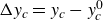 $\Delta y_c=y_c-y_c^0$
correspond to the minimum values of
$\Delta y_c=y_c-y_c^0$
correspond to the minimum values of
 $h$
. Notably, the particle returned to its initial separation distance after every half-period. Interestingly, in the case of P-flow (figure 4
b), the particles exhibited a unique behaviour. As indicated by the negative values of
$h$
. Notably, the particle returned to its initial separation distance after every half-period. Interestingly, in the case of P-flow (figure 4
b), the particles exhibited a unique behaviour. As indicated by the negative values of
 $\Delta y_c$
, the particle’s centre slightly approaches the wall before reaching its closest point. This phenomenon is in agreement with the theoretical results reported in previous studies (Yang & Leal Reference Yang and Leal1984). The observed oscillation of the separation distance during the swinging motion is likely due to the presence of a boundary wall, which is consistent with the findings in the literature (Bretherton Reference Bretherton1962; Yang & Leal Reference Yang and Leal1984; Gavze & Shapiro Reference Gavze and Shapiro1997; Mody & King Reference Mody and King2005).
$\Delta y_c$
, the particle’s centre slightly approaches the wall before reaching its closest point. This phenomenon is in agreement with the theoretical results reported in previous studies (Yang & Leal Reference Yang and Leal1984). The observed oscillation of the separation distance during the swinging motion is likely due to the presence of a boundary wall, which is consistent with the findings in the literature (Bretherton Reference Bretherton1962; Yang & Leal Reference Yang and Leal1984; Gavze & Shapiro Reference Gavze and Shapiro1997; Mody & King Reference Mody and King2005).
Under the C-flow in close proximity to the wall (figure 4 c), all trajectories collapsed, regardless of the initial conditions. The particle exhibited non-periodic translational motion aligned with the flow direction, with one end nearly contacting the wall while maintaining its separation distance instead of oscillating. In this orientation, the wall has a stabilizing influence on the rod-like particles, as reported in previous studies (Moses et al. Reference Moses, Advani and Reinhardt2001; Hijazi et al. Reference Hijazi, Yahia, Khater and Zoaeter2003). In contrast, for the P-flow (figure 4 d), all initial conditions except set S1 show a swinging motion where one end of the particle rests on the wall while the other end rotates around it, maintaining the initial separation distance after each period. However, for set S1, as shown in figure 4(d), the particles drift away from the wall. This behaviour is likely due to non-hydrodynamic effects, such as mechanical contacts; more details on this behaviour are provided in § 3.2.
Angular velocities are plotted over a single orbit period at
 $A=6.1$
for set S1; angular velocities are non-dimensionalized with the local shear rate. For reference, Jeffery’s solutions from (2.3a
) and (2.3b
), along with C-flow data at
$A=6.1$
for set S1; angular velocities are non-dimensionalized with the local shear rate. For reference, Jeffery’s solutions from (2.3a
) and (2.3b
), along with C-flow data at
 $y_c^0/d=4.4$
, are also plotted for comparison: (a)
$y_c^0/d=4.4$
, are also plotted for comparison: (a)
 $\dot {\phi }/\dot {\gamma }$
in time, (b)
$\dot {\phi }/\dot {\gamma }$
in time, (b)
 $\dot {\phi }/\dot {\gamma }$
in
$\dot {\phi }/\dot {\gamma }$
in
 $\phi$
angle and (c)
$\phi$
angle and (c)
 $\dot {\theta }/\dot {\gamma }$
in time.
$\dot {\theta }/\dot {\gamma }$
in time.

The angular velocities of the particles in periodic orbits were further analysed at both separation distances. Among the initial orientation conditions of sets S1–S4, only the results for set S1, which had the highest orbit constant, are shown as representative orbits in figure 5. We recall that
 $\theta$
is measured with respect to the
$\theta$
is measured with respect to the
 $z$
-axis, and
$z$
-axis, and
 $\phi$
is the angle in the
$\phi$
is the angle in the
 $xy$
-plane, measured clockwise from the
$xy$
-plane, measured clockwise from the
 $y$
-axis. The C-flow results at a distant wall location (
$y$
-axis. The C-flow results at a distant wall location (
 $y_c^0/d=4.4$
) are plotted along with the analytical solutions of (2.3a
) and (2.3b
).
$y_c^0/d=4.4$
) are plotted along with the analytical solutions of (2.3a
) and (2.3b
).
Figures 5(a) and 5(b) show a substantial decrease in
 $\dot {\phi }$
during the swinging motion when the particle aligns parallel to the wall, specifically at orientations
$\dot {\phi }$
during the swinging motion when the particle aligns parallel to the wall, specifically at orientations
 $\phi =\pi /2$
and
$\phi =\pi /2$
and
 $3\pi /2$
. In contrast, for orientations
$3\pi /2$
. In contrast, for orientations
 $\phi =\pi$
and
$\phi =\pi$
and
 $2\pi$
,
$2\pi$
,
 $\dot {\phi }$
exhibits slightly higher values compared to the Jeffery solution. This increase was most pronounced when the particle was closest to the wall (
$\dot {\phi }$
exhibits slightly higher values compared to the Jeffery solution. This increase was most pronounced when the particle was closest to the wall (
 $y_c^0/d=0.6$
), consistent with previous experimental observations (Moses et al. Reference Moses, Advani and Reinhardt2001). This behaviour can be attributed to the particle’s translational motion parallel to the wall, which induces a faster rate of rotation (Hsu & Ganatos Reference Hsu and Ganatos1994). Interestingly, the wall plays a dual role. Although it facilitates a faster rotation for certain orientations, it also exerts significant drag forces on the particle, particularly during motion parallel to the wall, which can ultimately slow down the overall angular velocity. As is evident in figure 5(c), the changes of the other angular velocity,
$y_c^0/d=0.6$
), consistent with previous experimental observations (Moses et al. Reference Moses, Advani and Reinhardt2001). This behaviour can be attributed to the particle’s translational motion parallel to the wall, which induces a faster rate of rotation (Hsu & Ganatos Reference Hsu and Ganatos1994). Interestingly, the wall plays a dual role. Although it facilitates a faster rotation for certain orientations, it also exerts significant drag forces on the particle, particularly during motion parallel to the wall, which can ultimately slow down the overall angular velocity. As is evident in figure 5(c), the changes of the other angular velocity,
 $\dot {\theta }$
, exhibit less deviation from the Jeffery solution compared with
$\dot {\theta }$
, exhibit less deviation from the Jeffery solution compared with
 $\dot {\phi }$
across all conditions. This suggests that the elongated period observed in figure 2 is primarily a consequence of the extended residence time of the particles along the wall. This extended time near the wall led to a moderate decrease in the oscillatory speed parallel to the wall, which manifested as the observed swinging motion.
$\dot {\phi }$
across all conditions. This suggests that the elongated period observed in figure 2 is primarily a consequence of the extended residence time of the particles along the wall. This extended time near the wall led to a moderate decrease in the oscillatory speed parallel to the wall, which manifested as the observed swinging motion.
Initial angular velocities of set S1 are shown for
 $A=6.1$
and 4.1. The shaded area (
$A=6.1$
and 4.1. The shaded area (
 $y_c^0/d \leqslant 0.5$
) represents the prohibited region where a bead cannot overlap with a solid wall. (a) Plot for
$y_c^0/d \leqslant 0.5$
) represents the prohibited region where a bead cannot overlap with a solid wall. (a) Plot for
 $\langle \dot {\phi }\rangle /\dot {\boldsymbol\gamma }$
: positive values indicate a clockwise rotation around the
$\langle \dot {\phi }\rangle /\dot {\boldsymbol\gamma }$
: positive values indicate a clockwise rotation around the
 $z$
-axis on the shear plane, whereas negative values signify an anticlockwise rotation. (b) Plot for
$z$
-axis on the shear plane, whereas negative values signify an anticlockwise rotation. (b) Plot for
 $\langle \dot {\theta }\rangle /\dot {\gamma }$
. Note the change in the sign of the C-flow when
$\langle \dot {\theta }\rangle /\dot {\gamma }$
. Note the change in the sign of the C-flow when
 $y_c^0/d\lt 1$
for (a) and (b). This corresponds to the rotational directions opposite to those of the Jeffery orbits, as indicated by the hatched regions.
$y_c^0/d\lt 1$
for (a) and (b). This corresponds to the rotational directions opposite to those of the Jeffery orbits, as indicated by the hatched regions.

Our analysis successfully clarifies the observed elongation of the period for oscillatory swinging motions near the wall, primarily attributed to a decrease in
 $\dot {\phi }$
. However, the mechanism behind the emergence of aperiodic motion near the wall in the C-flow (figures 3(g) and 4(c)) remains elusive. To address this, we conducted an additional analysis to examine how the changes in angular velocities correlate with varying distances from the wall. We calculated the angular velocities for the initial short time interval during which the particle–wall distance remained nearly constant. Figure 6 presents the initial angular velocity for each flow type as a function of the distance from the wall. Here, we define initial angular velocity as the average value over a short time interval
$\dot {\phi }$
. However, the mechanism behind the emergence of aperiodic motion near the wall in the C-flow (figures 3(g) and 4(c)) remains elusive. To address this, we conducted an additional analysis to examine how the changes in angular velocities correlate with varying distances from the wall. We calculated the angular velocities for the initial short time interval during which the particle–wall distance remained nearly constant. Figure 6 presents the initial angular velocity for each flow type as a function of the distance from the wall. Here, we define initial angular velocity as the average value over a short time interval
 $\Delta t$
. During this interval, the initial orientation
$\Delta t$
. During this interval, the initial orientation
 $\phi ^0=\pi /2$
changes by a small angle
$\phi ^0=\pi /2$
changes by a small angle
 $\Delta \phi =0.01\pi$
. For this time interval, the time-averaged values of the two angular velocities from the Jeffery solutions were calculated. For the
$\Delta \phi =0.01\pi$
. For this time interval, the time-averaged values of the two angular velocities from the Jeffery solutions were calculated. For the
 $\phi$
angle, it is evaluated analytically as
$\phi$
angle, it is evaluated analytically as
 $\langle \dot {\phi }\rangle ={1}/{\Delta \phi }\int _{\phi ^0}^{\phi ^0+\Delta \phi }\dot {\phi }\,{\mathrm{d}}\phi = {\dot {\gamma }}/{2} (1-{(A^2-1)}/{(A^2+1)}\, {\sin (\Delta \phi )\cos (\Delta \phi )}/{\Delta \phi } )$
, and for the
$\langle \dot {\phi }\rangle ={1}/{\Delta \phi }\int _{\phi ^0}^{\phi ^0+\Delta \phi }\dot {\phi }\,{\mathrm{d}}\phi = {\dot {\gamma }}/{2} (1-{(A^2-1)}/{(A^2+1)}\, {\sin (\Delta \phi )\cos (\Delta \phi )}/{\Delta \phi } )$
, and for the
 $\theta$
angle, it is evaluated numerically with
$\theta$
angle, it is evaluated numerically with
 $\langle \dot {\theta }\rangle ={1}/{\Delta t}\int _{0}^{\Delta t}\dot {\theta }\,{\mathrm{d}}t$
, where
$\langle \dot {\theta }\rangle ={1}/{\Delta t}\int _{0}^{\Delta t}\dot {\theta }\,{\mathrm{d}}t$
, where
 $\dot {\theta }$
and
$\dot {\theta }$
and
 $\dot {\phi }$
are given in (2.3a) and (2.3b
), respectively. The time-averaged angular velocities of the Jeffery solutions for
$\dot {\phi }$
are given in (2.3a) and (2.3b
), respectively. The time-averaged angular velocities of the Jeffery solutions for
 $A=6.1$
and 4.1 are plotted together in figure 6, and are represented by dashed lines.
$A=6.1$
and 4.1 are plotted together in figure 6, and are represented by dashed lines.
Figure 6(a) reveals a monotonic decrease in
 $\langle \dot {\phi }\rangle$
as the particle approaches the wall. This decrease deviates from the Jeffery solution approximately at
$\langle \dot {\phi }\rangle$
as the particle approaches the wall. This decrease deviates from the Jeffery solution approximately at
 $y_c^0/d=3$
, with the magnitude of deviation varying according to the flow type. Notably, C-flow exhibited a significantly larger decrease. Intriguingly, near the wall (
$y_c^0/d=3$
, with the magnitude of deviation varying according to the flow type. Notably, C-flow exhibited a significantly larger decrease. Intriguingly, near the wall (
 $y_c^0/d \lt 1$
) for C-flow, the value of
$y_c^0/d \lt 1$
) for C-flow, the value of
 $\langle \dot {\phi }\rangle$
becomes negative. This reversal of sign implies a change in rotation around the
$\langle \dot {\phi }\rangle$
becomes negative. This reversal of sign implies a change in rotation around the
 $z$
-axis, from clockwise to anticlockwise. Meanwhile, figure 6(b) shows the behaviour of
$z$
-axis, from clockwise to anticlockwise. Meanwhile, figure 6(b) shows the behaviour of
 $\langle \dot {\theta }\rangle$
. Unlike
$\langle \dot {\theta }\rangle$
. Unlike
 $\langle \dot {\phi }\rangle$
, it exhibits values close to the Jeffery solution everywhere except near the wall (
$\langle \dot {\phi }\rangle$
, it exhibits values close to the Jeffery solution everywhere except near the wall (
 $y_c^0/d \lt 1$
). In this region,
$y_c^0/d \lt 1$
). In this region,
 $\langle \dot {\theta }\rangle$
deviates from the Jeffery solution by adopting the opposite sign. This implies a decrease in
$\langle \dot {\theta }\rangle$
deviates from the Jeffery solution by adopting the opposite sign. This implies a decrease in
 $\theta$
, causing the particle to rotate towards the
$\theta$
, causing the particle to rotate towards the
 $x$
-axis and effectively align with the flow.
$x$
-axis and effectively align with the flow.
Visualization of the flow around a single particle (
 $A=6.1$
) in set S1. The plot combines streamlines (solid arrows) depicting the flow direction with a contour plot showing the
$A=6.1$
) in set S1. The plot combines streamlines (solid arrows) depicting the flow direction with a contour plot showing the
 $y$
-component of the disturbance velocity. The upward
$y$
-component of the disturbance velocity. The upward
 $y$
-component flow is red, while downward flow is blue. To account for the particle’s movement along the flow, the
$y$
-component flow is red, while downward flow is blue. To account for the particle’s movement along the flow, the
 $x$
-axis is defined in a body-centred coordinate frame (
$x$
-axis is defined in a body-centred coordinate frame (
 $x'$
). Plots for (a)
$x'$
). Plots for (a)
 $y_c^0/d=2$
(C-flow), (b)
$y_c^0/d=2$
(C-flow), (b)
 $y_c^0/d=2$
(P-flow), (c)
$y_c^0/d=2$
(P-flow), (c)
 $y_c^0/d=0.8$
(C-flow) and (d)
$y_c^0/d=0.8$
(C-flow) and (d)
 $y_c^0/d=0.8$
(P-flow). The
$y_c^0/d=0.8$
(P-flow). The
 $xy$
-plane was located at the centre of the particle in the
$xy$
-plane was located at the centre of the particle in the
 $z$
-direction.
$z$
-direction.

The flow field around the particles is significantly modified in the presence of a nearby wall. Here, we analyse the 2-D disturbance flow field generated by the suspended particle over the previously defined time interval
 $\Delta t$
. This disturbance flow, denoted by
$\Delta t$
. This disturbance flow, denoted by
 $\boldsymbol {u}'$
, is obtained by subtracting the flow field of the pure fluid (without the particle) from the time-averaged flow field extracted from simulations. To visualize this disturbance flow field, in figure 7 we present streamlines and a contour plot of the
$\boldsymbol {u}'$
, is obtained by subtracting the flow field of the pure fluid (without the particle) from the time-averaged flow field extracted from simulations. To visualize this disturbance flow field, in figure 7 we present streamlines and a contour plot of the
 $y$
-component velocity (
$y$
-component velocity (
 $u^{\prime}_y$
) on the
$u^{\prime}_y$
) on the
 $xy$
-plane at the centre of the particle in the
$xy$
-plane at the centre of the particle in the
 $z$
-direction.
$z$
-direction.
Figures 7(a) and 7(b) show that for both the flow types, when the particle is not close to the wall, the streamlines resemble the flow field generated by a force dipole. These streamlines exhibit near antisymmetry along the particle’s major and minor axes. This suggests that the liquid is pulled towards the upper head and lower tail of the particle, while being pushed away from the lower head and upper tail. Here, the head is designated as the first bead in the positive
 $x$
-direction, and the tail is designated as the last bead. These flow characteristics lead to a downward flow (blue) near the head, and an upward flow (red) near the tail, as shown in the figures. These flow patterns indicate that the particles could rotate clockwise in the
$x$
-direction, and the tail is designated as the last bead. These flow characteristics lead to a downward flow (blue) near the head, and an upward flow (red) near the tail, as shown in the figures. These flow patterns indicate that the particles could rotate clockwise in the
 $xy$
-plane, similar to the Jeffery solution. However, as the particles approach the wall, the flow patterns near the head and tail change depending on the flow type. In the P-flow (figure 7
d), the patterns remain largely similar to those observed when the particles are farther away. By contrast, the C-flow (figure 7
c) exhibits a reversal with an upward flow forming near the head and a downward flow forming near the tail. This explains the anticlockwise rotation of the
$xy$
-plane, similar to the Jeffery solution. However, as the particles approach the wall, the flow patterns near the head and tail change depending on the flow type. In the P-flow (figure 7
d), the patterns remain largely similar to those observed when the particles are farther away. By contrast, the C-flow (figure 7
c) exhibits a reversal with an upward flow forming near the head and a downward flow forming near the tail. This explains the anticlockwise rotation of the
 $\phi$
angle observed in figure 6(a).
$\phi$
angle observed in figure 6(a).
3.2. Pole-vault motion of a rod-like particle
Unlike the initial conditions described in the previous subsection, which result in 3-D ellipsoidal trajectories, the particles in set S0 exhibited circular motion in the
 $xy$
-plane far from the wall. When close to a solid surface, the Jeffery orbit becomes impossible because such motion leads to collisions with the wall. Previous experiments have revealed significant differences in the tumbling motion of particles near solid walls compared to their behaviour in the centre of a channel. Stover & Cohen (Reference Stover and Cohen1990) were the first to address this issue. They observed that particles with a high Jeffery orbit constant approaching within a distance of less than half the particle length from the wall experience an irreversible interaction. The particle abruptly moved away from the wall, reaching a stable distance of approximately half its length. This distance allowed for the characteristic tumbling motion of the particles. Additionally, previous studies reported a uniform decrease in angular velocity over time (Stover & Cohen Reference Stover and Cohen1990; Skjetne et al. Reference Skjetne, Ross and Klingenberg1997; Krochak, Olson & Martinez Reference Krochak, Olson and Martinez2010). Although these studies suggested the possibility of a non-hydrodynamic interaction between particle and wall, the precise nature of this interaction remains elusive.
$xy$
-plane far from the wall. When close to a solid surface, the Jeffery orbit becomes impossible because such motion leads to collisions with the wall. Previous experiments have revealed significant differences in the tumbling motion of particles near solid walls compared to their behaviour in the centre of a channel. Stover & Cohen (Reference Stover and Cohen1990) were the first to address this issue. They observed that particles with a high Jeffery orbit constant approaching within a distance of less than half the particle length from the wall experience an irreversible interaction. The particle abruptly moved away from the wall, reaching a stable distance of approximately half its length. This distance allowed for the characteristic tumbling motion of the particles. Additionally, previous studies reported a uniform decrease in angular velocity over time (Stover & Cohen Reference Stover and Cohen1990; Skjetne et al. Reference Skjetne, Ross and Klingenberg1997; Krochak, Olson & Martinez Reference Krochak, Olson and Martinez2010). Although these studies suggested the possibility of a non-hydrodynamic interaction between particle and wall, the precise nature of this interaction remains elusive.
Figure 8 depicts the translational and angular motions of a particle initially in set S0, positioned less than half the particle length away from the surface. Beginning with the uniform shear rate condition (figure 8
a), a notable feature across all initial positions is the presence of peaks in the
 $y_c$
graph. These peaks occur when the particle’s orientation becomes perpendicular to the wall at
$y_c$
graph. These peaks occur when the particle’s orientation becomes perpendicular to the wall at
 $\phi = \pi$
and
$\phi = \pi$
and
 $2\pi$
during each cycle. For a particle located far from the wall (
$2\pi$
during each cycle. For a particle located far from the wall (
 $y_c^0/d=3$
), the translational motion is reversible, and exhibits a repeated trajectory before and after each peak. Under the other two conditions, only the first peak is irreversible, whereas the subsequent peaks are reversible. This phenomenon was particularly pronounced for the initial condition closest to the wall (
$y_c^0/d=3$
), the translational motion is reversible, and exhibits a repeated trajectory before and after each peak. Under the other two conditions, only the first peak is irreversible, whereas the subsequent peaks are reversible. This phenomenon was particularly pronounced for the initial condition closest to the wall (
 $y_c^0/d=1.1$
). Figures 8(c) and 8(d) depict the particle orientations in chronological order before and after the first peak for these two distances. Comparing these figures allows us to directly visualize the difference between the reversible tumbling and irreversible pole-vaulting motions. As shown in figure 8(c), the particle makes perpendicular contact with the surface and rapidly detaches from it. In contrast, figure 8(d) shows that one end of the particle initially contacted the surface at a low angle, and maintained this contact until detachment after passing through a perpendicular orientation. During this contact, the tip of the particle primarily slides along the wall surface because of the lubricating film flow (see supplementary movie 7 for an example of a pole-vaulting motion). As shown in figure 8(b), the P-flow also exhibited pole-vaulting motion, similar to the C-flow. However, the higher shear rate near the wall caused it to appear earlier.
$y_c^0/d=1.1$
). Figures 8(c) and 8(d) depict the particle orientations in chronological order before and after the first peak for these two distances. Comparing these figures allows us to directly visualize the difference between the reversible tumbling and irreversible pole-vaulting motions. As shown in figure 8(c), the particle makes perpendicular contact with the surface and rapidly detaches from it. In contrast, figure 8(d) shows that one end of the particle initially contacted the surface at a low angle, and maintained this contact until detachment after passing through a perpendicular orientation. During this contact, the tip of the particle primarily slides along the wall surface because of the lubricating film flow (see supplementary movie 7 for an example of a pole-vaulting motion). As shown in figure 8(b), the P-flow also exhibited pole-vaulting motion, similar to the C-flow. However, the higher shear rate near the wall caused it to appear earlier.
Plot of pole-vaulting in shear flows for set S0 with
 $A=6.1$
. The particle is initially placed at three separation distances from the wall:
$A=6.1$
. The particle is initially placed at three separation distances from the wall:
 $y_c^0/d= 3$
, 2 and 1.1. Notably, these distances are less than half the particle length. Time evolution of the separation distance and the
$y_c^0/d= 3$
, 2 and 1.1. Notably, these distances are less than half the particle length. Time evolution of the separation distance and the
 $\phi$
angle for both (a) C-flow and (b) P-flow. (c,d) Schematic figures depicting the orientation of a particle near the wall at specific times during the first half period, for (c)
$\phi$
angle for both (a) C-flow and (b) P-flow. (c,d) Schematic figures depicting the orientation of a particle near the wall at specific times during the first half period, for (c)
 $y_c^0/d=3$
(C-flow) and (d)
$y_c^0/d=3$
(C-flow) and (d)
 $y_c^0/d=1.1$
(C-flow). Note the difference in the change of particle–wall distance before and after the collision in the figures.
$y_c^0/d=1.1$
(C-flow). Note the difference in the change of particle–wall distance before and after the collision in the figures.

Simulations revealed that the particle made repeated contact with the surface at every
 $180^\circ$
rotation. However, after the initial contact, the separation distance permanently increased to a value slightly greater than the original distance during pole-vault. Once the particle reached this stable distance, it underwent a tumbling motion. In other words, although the particle centre oscillates vertically during rotation, it maintains a consistent separation distance. This irreversible change in separation distance is attributed to the collisional forces generated by the mechanical contact between the particle’s tip and the wall during the pole-vaulting motion. The dependence of the displacement on the minimum hydrodynamic separation distance is explored in detail in Appendix C.
$180^\circ$
rotation. However, after the initial contact, the separation distance permanently increased to a value slightly greater than the original distance during pole-vault. Once the particle reached this stable distance, it underwent a tumbling motion. In other words, although the particle centre oscillates vertically during rotation, it maintains a consistent separation distance. This irreversible change in separation distance is attributed to the collisional forces generated by the mechanical contact between the particle’s tip and the wall during the pole-vaulting motion. The dependence of the displacement on the minimum hydrodynamic separation distance is explored in detail in Appendix C.
3.3. Particle orientation in slow sedimentation under shear flows near a wall
We now examine the motion of a rod-like particle sedimenting towards a wall within shear flows, with gravity directed along the velocity gradient direction of shear, i.e.
 $\boldsymbol {g}=-g\boldsymbol {\hat {y}}$
, where
$\boldsymbol {g}=-g\boldsymbol {\hat {y}}$
, where
 $g$
is the gravitational acceleration. Here, the gravitational force acting on each bead is treated as an additional external force applied in the
$g$
is the gravitational acceleration. Here, the gravitational force acting on each bead is treated as an additional external force applied in the
 $y$
-direction. The relative sedimentation rate under shear flow is quantified by a dimensionless number called the Shields number (
$y$
-direction. The relative sedimentation rate under shear flow is quantified by a dimensionless number called the Shields number (
 $Sh$
), which represents the ratio of the viscous transport to the gravitational settling velocity of a single particle (Jain, Tschisgale & Fröhlich Reference Jain, Tschisgale and Fröhlich2021):
$Sh$
), which represents the ratio of the viscous transport to the gravitational settling velocity of a single particle (Jain, Tschisgale & Fröhlich Reference Jain, Tschisgale and Fröhlich2021):
 \begin{align} Sh=\frac {u_{\tau }^2}{(\rho _p/\rho -1)gd}\,, \end{align}
where
 $\rho _p$
is the particle density. We define the characteristic friction velocity (Jain et al. Reference Jain, Tschisgale and Fröhlich2021)
$\rho _p$
is the particle density. We define the characteristic friction velocity (Jain et al. Reference Jain, Tschisgale and Fröhlich2021)
 $u_{\tau }$
, based on the shear stress of the sedimenting particle under shear flow, as
$u_{\tau }$
, based on the shear stress of the sedimenting particle under shear flow, as
 $\Gamma d$
. This definition reflects that a particle spends most of its time parallel to the wall during settling.
$\Gamma d$
. This definition reflects that a particle spends most of its time parallel to the wall during settling.
Time evolution of the dynamics of a sedimenting particle (
 $A=6.1$
) for sets S0, S1, S2 and S4 under two flow conditions: (a)–(g) C-flow and (h)–(n) P-flow. The initial separation distance (
$A=6.1$
) for sets S0, S1, S2 and S4 under two flow conditions: (a)–(g) C-flow and (h)–(n) P-flow. The initial separation distance (
 $y_c^0$
) is set to the channel’s midplane (
$y_c^0$
) is set to the channel’s midplane (
 $H/2$
) for all conditions. In (c) and (j), the steady-state
$H/2$
) for all conditions. In (c) and (j), the steady-state
 $\phi$
angles for sets S1, S2 and S4 are indicated with
$\phi$
angles for sets S1, S2 and S4 are indicated with ![]() . Also, (d)–(g) and (k)–(n) show the projected orientation trajectories on the
. Also, (d)–(g) and (k)–(n) show the projected orientation trajectories on the
 $xy$
-plane: (d,k) for set S0, (e,l) for set S1, (f,m) for set S2, and (g,n) for set S4, where the initial orientations are marked with
$xy$
-plane: (d,k) for set S0, (e,l) for set S1, (f,m) for set S2, and (g,n) for set S4, where the initial orientations are marked with ![]() , while the steady-state orientations are indicated with
, while the steady-state orientations are indicated with ![]() . Note that owing to the pole-vaulting and tumbling motions, there is no steady-state orientation in the special cases (d) and (k).
. Note that owing to the pole-vaulting and tumbling motions, there is no steady-state orientation in the special cases (d) and (k).

Experiments involving sedimenting particles in a quadratic film flowing down an inclined plane revealed that short fibres (with aspect ratio approximately 10) tended to align with the vorticity axis (Carlsson et al. Reference Carlsson, Lundell and Söderberg2007; Holm & Söderberg Reference Holm and Söderberg2007). According to Carlsson et al. (Reference Carlsson, Lundell and Söderberg2007), a liquid film with thickness
 $H=17\ \mathrm {mm}$
flowed down an inclined plate with a small angle
$H=17\ \mathrm {mm}$
flowed down an inclined plate with a small angle
 $\alpha =2.6^\circ$
in an experiment where the particle density was approximately
$\alpha =2.6^\circ$
in an experiment where the particle density was approximately
 $1300\ \mathrm {kg}\,{\mathrm{m}}^-{^3}$
and the liquid density was approximately
$1300\ \mathrm {kg}\,{\mathrm{m}}^-{^3}$
and the liquid density was approximately
 $1210\ \mathrm {kg}\,{\mathrm{m}}^{-3}$
. Fibres with diameter
$1210\ \mathrm {kg}\,{\mathrm{m}}^{-3}$
. Fibres with diameter
 $d=50\ \mu \mathrm{m}$
were suspended within this film. The average shear rate of the quadratic flow can be given by
$d=50\ \mu \mathrm{m}$
were suspended within this film. The average shear rate of the quadratic flow can be given by
 $\Gamma =g H\sin \alpha /2\nu =9.87\ \mathrm {s}^{-1}$
, where the kinematic viscosity of the liquid (
$\Gamma =g H\sin \alpha /2\nu =9.87\ \mathrm {s}^{-1}$
, where the kinematic viscosity of the liquid (
 $\nu$
) was
$\nu$
) was
 $3.83\times 10^{-4}\ \mathrm {m}^{2}\,{\mathrm{s}}^{-1}$
. Using these values, the Shields number can be calculated as
$3.83\times 10^{-4}\ \mathrm {m}^{2}\,{\mathrm{s}}^{-1}$
. Using these values, the Shields number can be calculated as
 $Sh=6.7\times 10^{-3}$
. Based on this value, we conducted the simulation with
$Sh=6.7\times 10^{-3}$
. Based on this value, we conducted the simulation with
 $Sh=7\times 10^{-3}$
.
$Sh=7\times 10^{-3}$
.
Sedimenting particles in both shear flows (shown in figure 9 and supplementary movies 4 and 5, depicting C-flow and P-flow, respectively) exhibit orientational behaviour similar to that of the neutrally buoyant particles discussed in §§ 3.1 and 3.2, although their vertical positions and orbital trajectories experienced drift. As the particles sedimented, the
 $y_c$
value decreased monotonically from the channel’s midplane to approximately
$y_c$
value decreased monotonically from the channel’s midplane to approximately
 $0.5d$
, except for the special case of set S0, which exhibited mixed tumbling and pole-vaulting motions (figures 9
a,h). Concurrently, the orientation angle
$0.5d$
, except for the special case of set S0, which exhibited mixed tumbling and pole-vaulting motions (figures 9
a,h). Concurrently, the orientation angle
 $\phi$
reaches a steady-state value approximately
$\phi$
reaches a steady-state value approximately
 $3\pi /2$
(as shown by in figures 9
e,j), indicating that
$3\pi /2$
(as shown by in figures 9
e,j), indicating that
 $p_y$
approaches zero (figures 9(e–g) for C-flow, and figures 9(l–n) for P-flow). These observations implied that the particles were aligned along a plane parallel to the wall.
$p_y$
approaches zero (figures 9(e–g) for C-flow, and figures 9(l–n) for P-flow). These observations implied that the particles were aligned along a plane parallel to the wall.
However, as the particle approaches the wall, the wall-induced effects on its
 $\theta$
angular motion and
$\theta$
angular motion and
 $p_x$
dynamics become specific to the type of shear flow. In C-flow, the absolute values of the
$p_x$
dynamics become specific to the type of shear flow. In C-flow, the absolute values of the
 $\theta$
orientation angle (figure 9
b) and
$\theta$
orientation angle (figure 9
b) and
 $p_x$
(figures 9
e–g) reach steady-state values
$p_x$
(figures 9
e–g) reach steady-state values
 $\pi /2$
and 1, respectively. This suggests that the sedimenting particles near the wall eventually aligned along the flow direction. Conversely, in P-flow, both the
$\pi /2$
and 1, respectively. This suggests that the sedimenting particles near the wall eventually aligned along the flow direction. Conversely, in P-flow, both the
 $\theta$
angle and
$\theta$
angle and
 $(p_x,p_y)$
approach zero with the oscillating (figure 9
i) or spiralling (figures 9
l–n) trajectories, suggesting that sedimenting particles near the wall swing and drift to an orientation perpendicular to the flow.
$(p_x,p_y)$
approach zero with the oscillating (figure 9
i) or spiralling (figures 9
l–n) trajectories, suggesting that sedimenting particles near the wall swing and drift to an orientation perpendicular to the flow.
Orientation distribution of the projection angle
 $\psi$
for particles near the wall. The angle
$\psi$
for particles near the wall. The angle
 $\psi$
represents the projection of the orientation vector
$\psi$
represents the projection of the orientation vector
 $\boldsymbol {p}$
onto the
$\boldsymbol {p}$
onto the
 $xz$
-plane, measured relative to the
$xz$
-plane, measured relative to the
 $x$
-axis (see inset schematic). Representative snapshot images of particles near the wall for C-flow and P-flow are shown in the insets.
$x$
-axis (see inset schematic). Representative snapshot images of particles near the wall for C-flow and P-flow are shown in the insets.

To statistically evaluate the angle distribution of particles near a wall, dilute suspensions with a low particle concentration (
 $nL^3=0.5$
) of particles with
$nL^3=0.5$
) of particles with
 $A=6.1$
were simulated (see supplementary movie 6 depicting particle dynamics at dilute concentrations). This concentration was chosen to be high enough for statistical analysis, but low enough to minimize particle–particle interactions, where
$A=6.1$
were simulated (see supplementary movie 6 depicting particle dynamics at dilute concentrations). This concentration was chosen to be high enough for statistical analysis, but low enough to minimize particle–particle interactions, where
 $n$
represents the number density of particles. To prevent particle overlap at close proximity, short-range forces, including elastic contact and lubrication (Ladd & Verberg Reference Ladd and Verberg2001; Nguyen & Ladd Reference Nguyen and Ladd2002), were introduced at the bead level between interacting beads belonging to different rod-like particles. After reaching a stationary state, the time-averaged and ensemble-averaged orientation distributions of the particles near the wall (defined as those with
$n$
represents the number density of particles. To prevent particle overlap at close proximity, short-range forces, including elastic contact and lubrication (Ladd & Verberg Reference Ladd and Verberg2001; Nguyen & Ladd Reference Nguyen and Ladd2002), were introduced at the bead level between interacting beads belonging to different rod-like particles. After reaching a stationary state, the time-averaged and ensemble-averaged orientation distributions of the particles near the wall (defined as those with
 $y_c\lt d$
) were calculated for three random initial configurations. This definition naturally excludes particles undergoing pole-vaulting behaviour, because most of these particles are oriented parallel to the planar wall. The orientation distribution, quantified by the angle
$y_c\lt d$
) were calculated for three random initial configurations. This definition naturally excludes particles undergoing pole-vaulting behaviour, because most of these particles are oriented parallel to the planar wall. The orientation distribution, quantified by the angle
 $\psi$
relative to flow direction, is presented in figure 10 for each type of flow. In this figure, the angle
$\psi$
relative to flow direction, is presented in figure 10 for each type of flow. In this figure, the angle
 $\psi$
represents the projection angle of the orientation vector onto the
$\psi$
represents the projection angle of the orientation vector onto the
 $xz$
-plane measured from the
$xz$
-plane measured from the
 $x$
-axis. An average of 3000 samples was used for each configuration (see supplementary movie 6).
$x$
-axis. An average of 3000 samples was used for each configuration (see supplementary movie 6).
This general trend strongly reflects the results observed for the single particle dynamics of sets S1–S4, as described previously. In C-flow, a sharp peak is observed at
 $\psi =0^\circ$
, indicating that most particles are aligned with the flow direction. In contrast, P-flow exhibits a peak at
$\psi =0^\circ$
, indicating that most particles are aligned with the flow direction. In contrast, P-flow exhibits a peak at
 $\psi =90^\circ$
, indicating that particles are primarily oriented perpendicular to the flow and exhibit a ‘rolling-sliding motion’ as they move along the flow. This behaviour can also be observed in supplementary movie 6. These observations are consistent with those reported in previous studies on inclined film flows of weakly sedimenting particles (Carlsson et al. Reference Carlsson, Lundell and Söderberg2007; Holm & Söderberg Reference Holm and Söderberg2007; Carlsson Reference Carlsson2009) and pressure-driven channel flows of strongly sedimenting particles (Wittmann et al. Reference Wittmann, Kulić, Stocco and Simmchen2024). The orientation distribution of particles in P-flow is notably broader, with a peak at approximately
$\psi =90^\circ$
, indicating that particles are primarily oriented perpendicular to the flow and exhibit a ‘rolling-sliding motion’ as they move along the flow. This behaviour can also be observed in supplementary movie 6. These observations are consistent with those reported in previous studies on inclined film flows of weakly sedimenting particles (Carlsson et al. Reference Carlsson, Lundell and Söderberg2007; Holm & Söderberg Reference Holm and Söderberg2007; Carlsson Reference Carlsson2009) and pressure-driven channel flows of strongly sedimenting particles (Wittmann et al. Reference Wittmann, Kulić, Stocco and Simmchen2024). The orientation distribution of particles in P-flow is notably broader, with a peak at approximately
 $\psi =90^\circ$
, indicating weaker alignment perpendicular to the flow compared to that of a single particle. This deviation from strong alignment can be attributed to weak hydrodynamic or contact interactions occurring during the swinging motion of particles near the wall.
$\psi =90^\circ$
, indicating weaker alignment perpendicular to the flow compared to that of a single particle. This deviation from strong alignment can be attributed to weak hydrodynamic or contact interactions occurring during the swinging motion of particles near the wall.
4. Conclusions
We numerically examined the orientational motion of rod-like particles near a wall in confined shear flows, Couette flow (C-flow) and Poiseuille flow (P-flow) using the LB method. The numerical results agree well with Jeffery’s theoretical predictions for particles positioned more than half of the particle length away from the wall.
Simulations of a single particle revealed that as the separation distance from the wall decreased, the orbits deviated significantly from the theoretical predictions. They flattened and became more parallel to the wall, exhibiting periodic swinging motions. The type of shear flow significantly affects the behaviour of a particle with a separation distance smaller than its diameter. In the P-flow, a particle maintains its swinging motion. Interestingly, under the C-flow, the particle ceases periodic motion and aligns with the flow direction. Visualization of the disturbance flow field around the suspended particles revealed that only the C-flow experienced a reversed flow pattern compared with Jeffery’s solution. This reversal explains the emergence of particle alignment in the flow direction in the vicinity of the wall under C-flow.
Simulations also successfully reproduced the qualitative behaviour of pole-vaulting near a wall in the experiments of Stover & Cohen (Reference Stover and Cohen1990), in which particles moved away from the wall in both types of shear flow. The transition from tumbling to pole-vaulting for particles occurred gradually as the separation distance decreased. The degree of displacement depends on the minimum hydrodynamic separation distance used in the proposed method.
In both shear flows, the weakly sedimenting particles exhibited an orientational behaviour similar to that of the neutrally buoyant particles. In the C-flow, the sedimenting particles eventually align with the flow direction. This behaviour was repeated for dilute suspensions. Conversely, in the P-flow, the spiralling trajectories of a single particle in the flow–gradient plane suggest that the sediment particles swing and drift in an orientation perpendicular to the flow. This behaviour is similar to observations in inclined film flow experiments (Carlsson et al. Reference Carlsson, Lundell and Söderberg2007; Holm & Söderberg Reference Holm and Söderberg2007; Carlsson Reference Carlsson2009), but with a broader distribution owing to interparticle interactions.
Overall, our results demonstrate that wall effects significantly modify the Jeffery orbits of rod-like particles in shear flow. We observed differences in these orbits depending on the type of shear flow through a planar channel. These findings go beyond theoretical predictions that do not account for hydrodynamic interactions with the wall, and are qualitatively consistent with previous experimental results.
Our findings strongly suggest that the type of shear flow significantly impacts the orientational dynamics of rod-like particles near boundaries. While modelling individual particles is feasible at low concentrations, higher concentrations necessitate a continuum approach based on particle number density in many cases. For spherical particles, a simple zero-flux boundary condition is sufficient. However, rod-like particles require additional considerations to account for restricted orientational configurations near the wall. A common approach involves imposing geometrical constraints on particle rotation, as demonstrated in the Schiek–Shaqfeh model (Schiek & Shaqfeh Reference Schiek and Shaqfeh1995; Krochak et al. Reference Krochak, Olson and Martinez2010). Our results, however, propose a simpler alternative: in C-flow, a boundary condition addressing orientation parallel to the flow direction could be applied, while in P-flow, a boundary condition normal to the flow direction, combined with rotational diffusion arising from interparticle interactions, may be more suitable.
Supplementary movies
Supplementary movies are available at https://doi.org/10.1017/jfm.2025.225.
Funding
This work was supported by the National Research Foundation of Korea (NRF) grants funded by the Ministry of Science and ICT(MSIT) of the Korea government (nos NRF-2018R1A5A1024127 and NRF-2021M3H4A6A01041234) and the BK21 FOUR Programme (4199990414461) funded by the Ministry of Education (MOE, Korea) and NRF.
Declaration of interests
The authors report no conflict of interest.
Appendix A. Orbits of a rod-like particle far from a wall
The rotational motions from our LB models were compared with those predicted by the Jeffery solutions for three representative
 $C_J$
values, far from the wall (figure 11). For the verification study, a cubic periodic box of size
$C_J$
values, far from the wall (figure 11). For the verification study, a cubic periodic box of size
 $23d$
(or equivalently,
$23d$
(or equivalently,
 $H/L=3.8$
for a particle with
$H/L=3.8$
for a particle with
 $A=6.1$
) was used, as shown in figures 11(a)–11(c). The particles were placed at the centre of the channel. A uniform shear with a shear rate
$A=6.1$
) was used, as shown in figures 11(a)–11(c). The particles were placed at the centre of the channel. A uniform shear with a shear rate
 $\dot {\gamma }$
is generated for the C-flow. The agreement between the simulations and predictions was excellent for all
$\dot {\gamma }$
is generated for the C-flow. The agreement between the simulations and predictions was excellent for all
 $C_J$
values.
$C_J$
values.
Time evolution of a rod-like particle’s orientation in a simple shear flow far from a wall. A rod-like particle with
 $A=6.1$
is analysed for three representative values,
$A=6.1$
is analysed for three representative values,
 $C_J = 10$
, 1 and 0.1, with
$C_J = 10$
, 1 and 0.1, with
 $T_J=2\pi (A_e+A_e^{-1})/\dot {\gamma }$
and
$T_J=2\pi (A_e+A_e^{-1})/\dot {\gamma }$
and
 $A_e/A=0.95$
in (a)–(c). The solid lines represent the theoretical values from the Jeffery solution, whereas the simulation results are shown as symbols. (a) Orientational trajectory on a unit sphere. (b) Polar angle
$A_e/A=0.95$
in (a)–(c). The solid lines represent the theoretical values from the Jeffery solution, whereas the simulation results are shown as symbols. (a) Orientational trajectory on a unit sphere. (b) Polar angle
 $\theta$
as a function of time over a single period. (c) Polar angle
$\theta$
as a function of time over a single period. (c) Polar angle
 $\phi$
as a function of time over a single period. Notably, the trajectory of the polar angle
$\phi$
as a function of time over a single period. Notably, the trajectory of the polar angle
 $\phi$
is independent of the orbit constant. (d) Comparison of the orbit periods as a function of the aspect ratio.
$\phi$
is independent of the orbit constant. (d) Comparison of the orbit periods as a function of the aspect ratio.

To investigate the effect of aspect ratio on the rotation period, we performed additional simulations with various particle aspect ratios. To ensure that the particles remained sufficiently far away from the walls, we employed a cubic periodic box of variable sizes. In all cases, the
 $H/L$
ratio remained above 2.7. The particles were placed at the centre of the channel in each simulation. As shown in figure 11(d), the simulated periods increased with the aspect ratio, which is qualitatively similar to Jeffery’s predictions. Symbols represent the average value obtained for the three
$H/L$
ratio remained above 2.7. The particles were placed at the centre of the channel in each simulation. As shown in figure 11(d), the simulated periods increased with the aspect ratio, which is qualitatively similar to Jeffery’s predictions. Symbols represent the average value obtained for the three
 $C_J$
values (10, 1 and 0.1), with error bars indicating the standard deviation due to variations in the initial particle orientations. The error bars are small enough to be less than the size of the symbols. The observed quantitative discrepancies between Jeffery’s predictions and the simulated periods can be attributed to the fundamental difference in particle shape. Jeffery’s solution assumes ellipsoids for the calculations, whereas our chain-of-spheres model diverges from this assumption. An illustrative example of this shape difference is the deviation of the experimental rotational periods for cylinders from Jeffery’s model predictions (Anczurowski & Mason Reference Anczurowski and Mason1968; Cox Reference Cox1971; Stover & Cohen Reference Stover and Cohen1990). Non-ellipsoidal particles can be addressed by introducing an effective value
$C_J$
values (10, 1 and 0.1), with error bars indicating the standard deviation due to variations in the initial particle orientations. The error bars are small enough to be less than the size of the symbols. The observed quantitative discrepancies between Jeffery’s predictions and the simulated periods can be attributed to the fundamental difference in particle shape. Jeffery’s solution assumes ellipsoids for the calculations, whereas our chain-of-spheres model diverges from this assumption. An illustrative example of this shape difference is the deviation of the experimental rotational periods for cylinders from Jeffery’s model predictions (Anczurowski & Mason Reference Anczurowski and Mason1968; Cox Reference Cox1971; Stover & Cohen Reference Stover and Cohen1990). Non-ellipsoidal particles can be addressed by introducing an effective value
 $A_e$
instead of
$A_e$
instead of
 $A$
. In our chain-of-spheres model, this ratio has values
$A$
. In our chain-of-spheres model, this ratio has values
 $A_e/A=0.95$
and 1.0 for
$A_e/A=0.95$
and 1.0 for
 $A=6.1$
and 4.1, respectively.
$A=6.1$
and 4.1, respectively.
Appendix B. Effects of
 $K_R/K_B$
on angular motions
$K_R/K_B$
on angular motions

Angular motions for a particle with
 $A = 6.1$
at
$A = 6.1$
at
 $C_J=1$
in the variation of
$C_J=1$
in the variation of
 $K_R/K_B$
with a fixed value of
$K_R/K_B$
with a fixed value of
 $K_B$
. The modulus ratio (
$K_B$
. The modulus ratio (
 $K_R/K_B$
) varies as
$K_R/K_B$
) varies as
 $0,\ 2\times 10^{-6},\ 4\times 10^{-6},\ 1\times 10^{-4}$
. Here, the theoretical value of
$0,\ 2\times 10^{-6},\ 4\times 10^{-6},\ 1\times 10^{-4}$
. Here, the theoretical value of
 $T_J$
is calculated using
$T_J$
is calculated using
 $2\unicode{x03C0} (A_e+A_e^{-1})/\Gamma$
with
$2\unicode{x03C0} (A_e+A_e^{-1})/\Gamma$
with
 $A_e/A=0.95$
.
$A_e/A=0.95$
.

To determine an appropriate value for
 $K_R$
, we analyse the particle’s rotational behaviour as the
$K_R$
, we analyse the particle’s rotational behaviour as the
 $K_R/K_B$
ratio varies, while keeping
$K_R/K_B$
ratio varies, while keeping
 $K_B$
fixed at
$K_B$
fixed at
 $K_B = \pi Ed^3/64$
with
$K_B = \pi Ed^3/64$
with
 $E=100$
. Figure 12 shows an example of the time evolution of the rotation angles for
$E=100$
. Figure 12 shows an example of the time evolution of the rotation angles for
 $C_J=1$
. In this study, a uniform shear flow was generated by employing a cubic periodic box with size
$C_J=1$
. In this study, a uniform shear flow was generated by employing a cubic periodic box with size
 $17d$
(equivalent to
$17d$
(equivalent to
 $H/L=2.7$
for a particle with
$H/L=2.7$
for a particle with
 $A=6.1$
). The particle exhibits rotation, and preferentially spends more time aligned with the flow–vorticity plane (i.e.
$A=6.1$
). The particle exhibits rotation, and preferentially spends more time aligned with the flow–vorticity plane (i.e.
 $\phi =\pi /2$
or
$\phi =\pi /2$
or
 $3\pi /2$
) in the case without rotational constraints (
$3\pi /2$
) in the case without rotational constraints (
 $K_R/K_B=0$
) compared to the Jeffery solution (figure 12
b). As the
$K_R/K_B=0$
) compared to the Jeffery solution (figure 12
b). As the
 $K_R$
value increases, the period of the angular motion gradually decreases, converging to the Jeffery solution when
$K_R$
value increases, the period of the angular motion gradually decreases, converging to the Jeffery solution when
 $K_R/K_B$
reaches
$K_R/K_B$
reaches
 $10^{-4}$
. While graphs were not drawn for values greater than
$10^{-4}$
. While graphs were not drawn for values greater than
 $K_R/K_B=10^{-4}$
, the period is understood to remain constant beyond this point. For simplicity, we used
$K_R/K_B=10^{-4}$
, the period is understood to remain constant beyond this point. For simplicity, we used
 $K_R/K_B = 1$
throughout this study.
$K_R/K_B = 1$
throughout this study.
Appendix C. Influence of minimum hydrodynamic separation distance on pole-vaulting motion
(a) Normal force
 $F_{lub,N}$
acting on a spherical particle with radius
$F_{lub,N}$
acting on a spherical particle with radius
 $a$
as it approaches a planar surface at speed
$a$
as it approaches a planar surface at speed
 $U$
. The drag force obtained from LB simulations is plotted, normalized by the drag force on an isolated sphere,
$U$
. The drag force obtained from LB simulations is plotted, normalized by the drag force on an isolated sphere,
 $F_0=6\pi \eta aU$
. The solid line represents the theoretical prediction from lubrication theory (Cichocki & Jones Reference Cichocki and Jones1998), as detailed in (C1). A lower limit on the surface distance for lubrication correction,
$F_0=6\pi \eta aU$
. The solid line represents the theoretical prediction from lubrication theory (Cichocki & Jones Reference Cichocki and Jones1998), as detailed in (C1). A lower limit on the surface distance for lubrication correction,
 $h_{min}$
, is introduced as
$h_{min}$
, is introduced as
 $h=\max(h, h_{min})$
. (b) Time evolution of the separation distance of a rod-like particle (
$h=\max(h, h_{min})$
. (b) Time evolution of the separation distance of a rod-like particle (
 $A=6.1$
) initially placed at
$A=6.1$
) initially placed at
 $y_c^0/d=1.1$
in orientation set S0 under C-flow with uniform shear rate
$y_c^0/d=1.1$
in orientation set S0 under C-flow with uniform shear rate
 $\dot {\gamma }$
. (c,d) Schematic figures depicting the orientation of a particle near the wall at specific times during the first half period, for (c)
$\dot {\gamma }$
. (c,d) Schematic figures depicting the orientation of a particle near the wall at specific times during the first half period, for (c)
 $h_{min}=10^{-2}\delta$
and (d)
$h_{min}=10^{-2}\delta$
and (d)
 $h_{min}=0$
. Supplementary movie 7 provides a visualization of the particle’s movement and changes in orientation over time.
$h_{min}=0$
. Supplementary movie 7 provides a visualization of the particle’s movement and changes in orientation over time.

In LB simulations, lubrication forces derived from theoretical models have been successfully incorporated to account for the unresolved hydrodynamic interactions at small separation distances (Nguyen & Ladd Reference Nguyen and Ladd2002). These forces can involve setting a lower limit (
 $h_{min}$
) for the surface distance, which determines the maximum lubrication force at contact. This limit can represent the inherent roughness of the physical surface (Davis et al. Reference Davis, Zhao, Galvin and Wilson2003; Felsted et al. Reference Felsted, Chun, Schenter, Bard, Xia and Pauzauskie2023) or be used to avoid excessively large lubrication forces for numerical stability (Bartuschat & Rüde Reference Bartuschat and Rüde2015; Rettinger & Rüde Reference Rettinger and Rüde2018). By applying this lower limit
$h_{min}$
) for the surface distance, which determines the maximum lubrication force at contact. This limit can represent the inherent roughness of the physical surface (Davis et al. Reference Davis, Zhao, Galvin and Wilson2003; Felsted et al. Reference Felsted, Chun, Schenter, Bard, Xia and Pauzauskie2023) or be used to avoid excessively large lubrication forces for numerical stability (Bartuschat & Rüde Reference Bartuschat and Rüde2015; Rettinger & Rüde Reference Rettinger and Rüde2018). By applying this lower limit
 $h=\max(h, h_{min})$
, the model allows for mechanical contact between the particle and wall, moving beyond purely hydrodynamic interactions.
$h=\max(h, h_{min})$
, the model allows for mechanical contact between the particle and wall, moving beyond purely hydrodynamic interactions.
The effect of
 $h_{min}$
on the normal lubrication force is illustrated in figure 13(a). The figure depicts a spherical particle with radius
$h_{min}$
on the normal lubrication force is illustrated in figure 13(a). The figure depicts a spherical particle with radius
 $a$
approaching a planar wall at speed
$a$
approaching a planar wall at speed
 $U$
. The solid line represents the theoretical values from the literature (Cichocki & Jones Reference Cichocki and Jones1998), and is given by
$U$
. The solid line represents the theoretical values from the literature (Cichocki & Jones Reference Cichocki and Jones1998), and is given by
 \begin{equation} \frac {F_{lub,N}}{6\pi \eta a U}=\frac {a}{h}+\frac {1}{5}\ln \left (1+\frac {a}{h}\right )+0.97127+\frac {1}{21}\frac {h}{a}\ln \left (1+\frac {a}{h}\right ). \end{equation}
The case with
 $h_{min}=0$
perfectly matches the singular theoretical solution. Setting non-zero values of
$h_{min}=0$
perfectly matches the singular theoretical solution. Setting non-zero values of
 $h_{min}$
, such as
$h_{min}$
, such as
 $10^{-6}\delta , 10^{-4}\delta, 10^{-2}\delta$
, effectively determines the corresponding maximum lubrication force value.
$10^{-6}\delta , 10^{-4}\delta, 10^{-2}\delta$
, effectively determines the corresponding maximum lubrication force value.
Figure 13(b) illustrates the transition from tumbling motion to pole-vaulting motion for a rod-like particle with
 $A = 6.1$
as
$A = 6.1$
as
 $h_{min}$
varies. The particles were initially aligned parallel to the wall (set S0) with centre position
$h_{min}$
varies. The particles were initially aligned parallel to the wall (set S0) with centre position
 $y_c^0/d = 1.1$
. The figure shows the time evolution of the particle’s centre position relative to the wall owing to interactions during its tumbling motion. The particle rebound behaviour exhibited an increasing placement of the centre position after the elastic collision as
$y_c^0/d = 1.1$
. The figure shows the time evolution of the particle’s centre position relative to the wall owing to interactions during its tumbling motion. The particle rebound behaviour exhibited an increasing placement of the centre position after the elastic collision as
 $h_{min}$
increases, in contrast to the case of purely hydrodynamic interactions with
$h_{min}$
increases, in contrast to the case of purely hydrodynamic interactions with
 $h_{min}=0$
. Comparing the visualized data for
$h_{min}=0$
. Comparing the visualized data for
 $h_{min}=10^{-2}\delta$
and
$h_{min}=10^{-2}\delta$
and
 $h_{min}=0$
demonstrates the contrasting effects of the inclusion of irreversible mechanical collisions (figure 13
c) versus the reversible hydrodynamic interactions (figure 13
d). It is noteworthy that pole-vaulting was reproduced without resorting to any special treatment, simply by setting a limit on the hydrodynamic separation distance. Throughout this paper, we employed
$h_{min}=0$
demonstrates the contrasting effects of the inclusion of irreversible mechanical collisions (figure 13
c) versus the reversible hydrodynamic interactions (figure 13
d). It is noteworthy that pole-vaulting was reproduced without resorting to any special treatment, simply by setting a limit on the hydrodynamic separation distance. Throughout this paper, we employed
 $h_{min} = 10^{-2}\delta$
to capture the non-hydrodynamic interactions during tumbling, as observed in the experiments (Stover & Cohen Reference Stover and Cohen1990).
$h_{min} = 10^{-2}\delta$
to capture the non-hydrodynamic interactions during tumbling, as observed in the experiments (Stover & Cohen Reference Stover and Cohen1990).
Appendix D. Orbit drift under small inertia
Time evolution of orbits for a particle with
 $A = 6.1$
for sets S0, S1, S2 and S4 at two different confinement ratios, (a)
$A = 6.1$
for sets S0, S1, S2 and S4 at two different confinement ratios, (a)
 $H/L=3$
and (b)
$H/L=3$
and (b)
 $H/L=1.5$
, under C-flow conditions for
$H/L=1.5$
, under C-flow conditions for
 $0\leqslant t/T_J\leqslant 12$
. To ensure minimal wall effects, particles were positioned far from the walls (
$0\leqslant t/T_J\leqslant 12$
. To ensure minimal wall effects, particles were positioned far from the walls (
 $y_c^0/d \gt 4$
). Specifically, the particle centre was placed at the midplane of each channel (
$y_c^0/d \gt 4$
). Specifically, the particle centre was placed at the midplane of each channel (
 $y_c^0/d=18.3$
and
$y_c^0/d=18.3$
and
 $9.2$
, respectively). Jeffery orbits (reference) are plotted as dots on the 3-D plots. Arrows indicate the direction of time evolution for trajectories spiralling outwards from these reference orbits towards the shear plane (
$9.2$
, respectively). Jeffery orbits (reference) are plotted as dots on the 3-D plots. Arrows indicate the direction of time evolution for trajectories spiralling outwards from these reference orbits towards the shear plane (
 $p_x$
$p_x$
 $p_y$
plane). (c) The orbit drift over time is shown by the increase in
$p_y$
plane). (c) The orbit drift over time is shown by the increase in
 $\theta$
, evaluated at
$\theta$
, evaluated at
 $\phi =0$
for each period.
$\phi =0$
for each period.

A commonly observed effect of finite inertia, both theoretically (Subramanian & Koch Reference Subramanian and Koch2005) and experimentally (Di Giusto et al. Reference Di Giusto, Bergougnoux, Marchioli and Guazzelli2024), is orbit drift. In the Jeffery solution, valid at zero Reynolds number, the orbit trajectories of particles form stationary closed loops that are determined by the particle’s initial orientation. However, under finite inertia, the orbits of rod-like particles gradually shift towards the shear plane over time, leading to an increase in both the orbit constant and the angle
 $\theta$
relative to the original trajectory. This observable orbit drift due to inertia generally occurs in flows with sufficiently high
$\theta$
relative to the original trajectory. This observable orbit drift due to inertia generally occurs in flows with sufficiently high
 $Re$
. As demonstrated in the experimental results of Di Giusto et al. (Reference Di Giusto, Bergougnoux, Marchioli and Guazzelli2024), no notable changes were observed for
$Re$
. As demonstrated in the experimental results of Di Giusto et al. (Reference Di Giusto, Bergougnoux, Marchioli and Guazzelli2024), no notable changes were observed for
 $Re \lt 0.1$
across various initial configurations, with significant inertial effects becoming evident only at
$Re \lt 0.1$
across various initial configurations, with significant inertial effects becoming evident only at
 $Re \gt \mathcal {O}(1)$
.
$Re \gt \mathcal {O}(1)$
.
Following the established research on orbit drift, we investigated the inertia-induced orbit drift of particles with
 $A=6.1$
in C-flow at
$A=6.1$
in C-flow at
 $Re=0.02$
. The particles were initially placed at the midplane in two different channels:
$Re=0.02$
. The particles were initially placed at the midplane in two different channels:
 $H/L=3$
(figure 14
a) and
$H/L=3$
(figure 14
a) and
 $H/L=1.5$
(figure 14
b). Figures 14(a) and 14(b) demonstrate that channel width has a negligible effect on orbit drift. The band-like trajectories observed in sets S1 and S2, as marked by the black arrows, indicate the progression of orbit drift. However, further analysis of the drift rate, reflected by the gradual increase in
$H/L=1.5$
(figure 14
b). Figures 14(a) and 14(b) demonstrate that channel width has a negligible effect on orbit drift. The band-like trajectories observed in sets S1 and S2, as marked by the black arrows, indicate the progression of orbit drift. However, further analysis of the drift rate, reflected by the gradual increase in
 $\theta$
over time shown in figure 14(c), suggests that orbit drift is negligible within the time frame considered in this study.
$\theta$
over time shown in figure 14(c), suggests that orbit drift is negligible within the time frame considered in this study.


 Open access