


Introduction
The 122 GHz industrial, scientific, and medical (ISM) frequency band is very attractive for radar and wireless communication applications because of the license-free access and the high frequency and bandwidth allowing high-resolution measurements or high data rates. Antennas are a key element in every radar system. They are responsible for the spatial radiation and influence the available range and the bandwidth of the system. At frequencies above 60 GHz, the antennas are often placed on chip [Reference Ng and Kissinger1,Reference Goettel, Pahl, Kutschker, Malz, Pfeiffer and Zwick2] or integrated in different package technologies [Reference Beer, Gulan, Rusch and Zwick3,Reference Fischer, Tong, Hamidipour, Maurer and Stelzer4]. Nevertheless, there have been approaches to design antennas on printed circuit boards (PCB) above 100 GHz using patch antennas [Reference Hasan, Ahmad, Lu, Kissinger and Ng5,Reference Herrero and Schoebel6] with expensive high-frequency laminates. When usingsubstrate integrated waveguide (SIW) structures as feed leaky wave antennas [Reference Lyu, Meng, Yang, Erni, Wu and Wu7–Reference Sharma, Sarkar, Biswas and Akhtar9] are a common choice. Typically leaky wave antennas only focus the radiating fields in one plane unless using an array approach with several parallel SIW lines. Both, patch antennas and leaky wave antennas, radiate with the Poynting vector approximately perpendicular to the PCB plane.
The aim of this work is to develop a suitable antenna for a discrete SIW six-port radar system on low-cost PCB technology operating at 122 GHz which requires lateral radiation of the antennas similar as presented in [Reference Mann, Will, Reissland, Lurz, Lindner, Linz, Weigel and Koelpin10] for 61 GHz. There has been previous research published on Vivaldi-shaped antennas which are often also using a SIW feeding structure. The main difference to our work is that those antennas are mostly operating at a significant lower frequency band [Reference Kazemi, Fathy and Sadeghzadeh11–Reference Suo, Li and Chen15]. Therefore, the published approaches had less challenging requirements regarding substrate material and fabrication tolerances and process. Designs covering frequencies up to 90 GHz [Reference Mirbeik-Sabzevari, Li, Garay, Nguyen, Wang and Tavassolian16] or even 120 GHz [Reference Taringou, Dousset, Bornemann and Wu17] demand substrate cutouts or gaps in the substrate metallization below  $100\,\mu {\rm m}$ leading to increasing manufacturing costs. Additionally, none of those designs feature the cost-efficient Rogers RO4350B substrate. The antenna design presented in the following sections uses a similar SIW fed Vivaldi structure and is supposed to operate in the 122 GHz ISM band. To ensure low manufacturing costs and fast prototyping at those very high frequencies, the antenna is based on a very low-cost Rogers RO4350B substrate and designed as simple as possible to be not relied on substrate cutouts, structures below $100\,\mu {\rm m}$ or any other configuration making the manufacturing process more complex.
Antenna design
The SIW technology is very suitable for high-frequency circuit design [Reference Bozzi, Georgiadis and Wu18]. The electric characteristics are only dependent on the placement of the vias and the material properties of the substrate. Therefore, no expensive PCB fabrication technology is necessary to achieve very tiny structures as usually needed in high-frequency design.
The whole design is based on a single double-sided metallized RO4350B high-frequency substrate. The height of the substrate is chosen to 0.254 mm. The main advantage of this substrate is the low price compared with other high-frequency substrates. The datasheet [19] provides values for the dielectric constant and dissipation factor only up to 40 GHz respectively 10 GHz. The frequency range of this work clearly exceeds those limits. The losses are expected to be significantly higher and a design  $\epsilon _r$ of approximately 3.0 has been derived from previous designs. For the SIW feed line, an insertion loss of approximately $2.4\,{\rm dB}/{\rm cm}$ could be discovered.
The actual antenna design is based on a similar approach for the 61 GHz ISM band presented in [Reference Mann, Lurz, Linz, Lindner, Will, Wibbing, Weigel and Koelpin20] and modified for operation at 122 GHz without any additional layers or shielding. The structure of the first developed antenna with SIW feed is depicted in Fig. 1 on the left with some of the main design parameters for the antenna structure and the SIW feed. The antenna structure is placed in right angles to the SIW feed line. A Vivaldi-shaped structure and a slot on both metallic layers are used to guide the fields to the edge of the substrate. A via placed in the SIW line directs the fields from the SIW line into the antenna structure. The exact placement of the via can be used for matching purpose.
Layout of the SIW fed vivaldi-shaped antenna 1 (left) and extended substrate antenna 2 (right) with the main design parameters (top view).
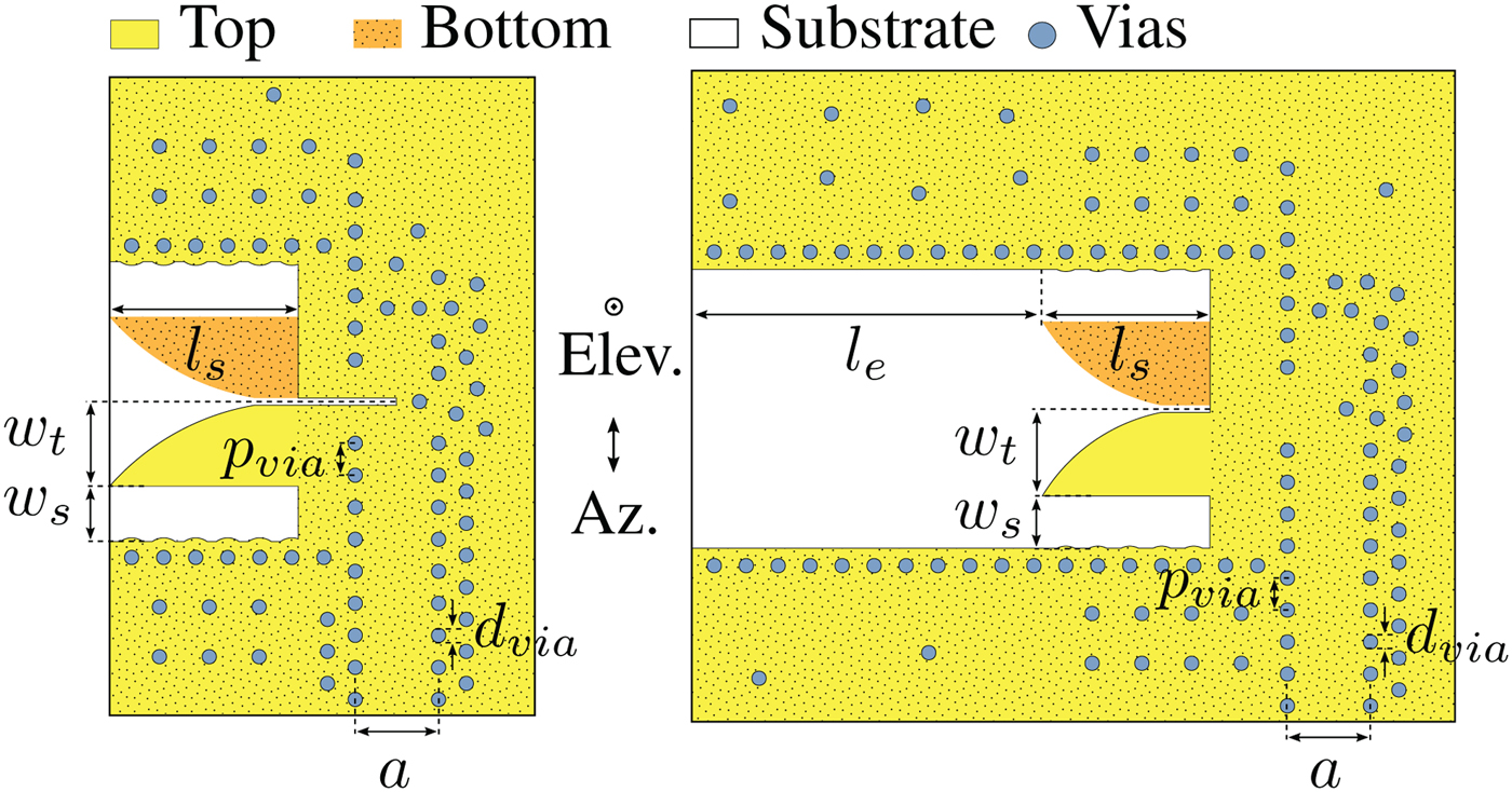
The transmission characteristics of the SIW line are mainly dependent on its width a which is chosen to 1.17 mm. The diameter of the vias  $d_{via}=0.2\,{\rm mm}$ and the via spacing $p_{via}=0.45\,{\rm mm}$ are a compromise between transmission behavior and PCB manufacturing technology. The dimensions of the antenna structures $l_s=2.65\,{\rm mm}$, $w_t=1.19\,{\rm mm}$, and $w_s=0.775\,{\rm mm}$ are optimized regarding the radiation pattern and the input matching. The total width (3.93 mm) and length (3.45 mm) of the antenna are both below
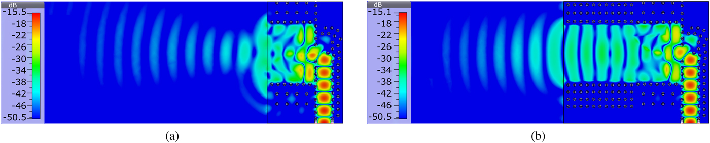
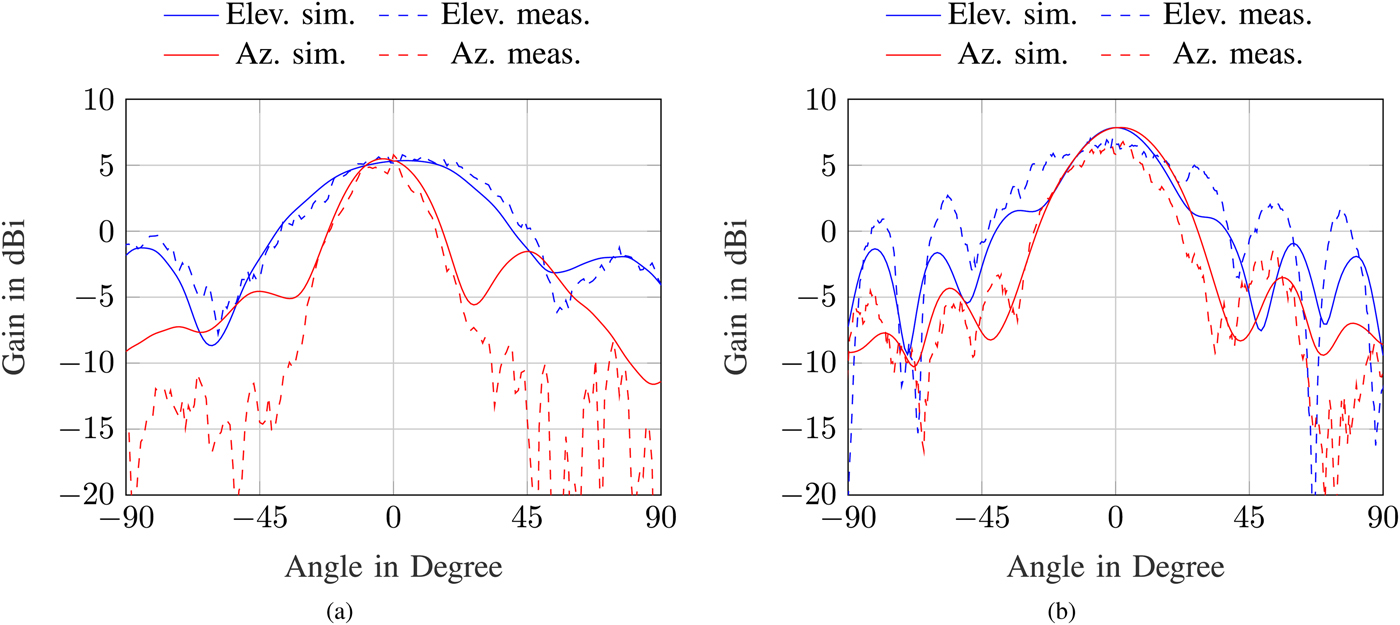
  $2\lambda _0$. Therefore, the directivity of the element might be limited. Fig. 2(a) shows the simulated electric field distribution in cross-section for the designed antenna with SIW feed radiating into free-space at 122.5 GHz. The simulated radiation pattern for this antenna is shown in Fig. 3(a) at 122.5 GHz. The design results in high directivity in the azimuth plane and a gain of 5.54 dBi.
Simulated electric field distribution of the designed antenna structures with SIW feed and radiation into free-space for (a) antenna 1 and (b) antenna 2.
Simulated and measured radiation patterns in azimuth and elevation for (a) antenna 1 and (b) antenna 2 at 122.5 GHz.
In order to increase the antenna gain, a second version of the antenna has been developed. The modified antenna structure is presented in Fig. 1 on the right. Compared with the previous version, the substrate behind the Vivaldi structure is extended by the length  $l_e$. Instead of radiating direct into free-space, the wave is guided inside the substrate by a via fence to the edge of the PCB. Additionally, the feeding of the Vivaldi structure is simplified by the removal of the slot. Therefore, the new design is making less demands to the PCB manufacturing process.
Simulations resulted in the length  $l_e=4.935\,{\rm mm}$ to maximize the antenna gain. The other dimensions were slightly adjusted to match the antenna structure to the SIW feed resulting in $l_s=2.36\,{\rm mm}$, $w_t=1.23\,{\rm mm}$, and $w_s=0.738\,{\rm mm}$. The parameters of the SIW feed $p_{via}$, $d_{via}$, and a are identical for both antenna designs. The simulated electric field distribution for the second antenna is depicted in Fig. 2(b). It can be observed that the small tilt of the main beam direction in the azimuth plane for antenna 1 is corrected by the second design.
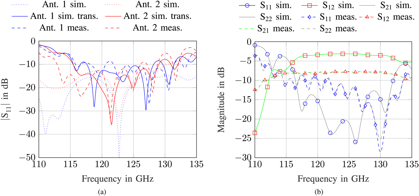
The directivity pattern of the second antenna structure is also presented in Fig. 3(b). The design shows an improved gain of 7.87 dBi at 122.5 GHz. Additionally, the directivity in the elevation plane is increased. The simulated free-space reflection coefficient is presented in Fig. 4(a) for both antenna designs with and without the transition. The pure antennas show good matching over a wide frequency range. The transition slightly limits the bandwidth and decreases the matching. Fig. 4(b) shows the simulated S-parameters of the proposed transition in back-to-back-configuration. The 122 GHz ISM band is well covered.
(a) Simulated and measured free-space reflection coefficient for both antenna designs and (b) simulated and measured S-parameters for the transition in back-to-back configuration.
Measurement results
The characterization of the antenna is performed with a vector network analyzer (VNA) and a rotation stage. In order to connect the antenna with the VNA, a transition from rectangular waveguide (WR-06) to SIW is needed. Due to the high frequency, and therefore very small structures, a single slot is placed in the copper of the SIW line to allow coupling from a rectangular waveguide into the substrate. Appropriate drills are provided to attach the flange of the rectangular waveguide (UG-387/U-M) on the SIW line. Fig. 5 shows a photograph of the fabricated antennas with the transition to rectangular waveguide together with a reference for the size of the structures. Additionally, a 24 dBi horn antenna is placed next to the designed and fabricated antennas. It can be clearly seen that the antenna structures itself are very compact. The transition to rectangular waveguide and both antenna structures are highlighted in an enlarged view.
Photograph of the fabricated antennas 1 and 2 with highlighted transition from SIW to rectangular waveguide and the antenna structures together with a 24 dBi horn antenna in D band.

The measured  $\vert S_{11} \vert$ of both antennas is presented in Fig. 4(a). The measured reflection coefficients clearly differ from the simulated results without transition but match the simulations performed with the transition. The frequency behavior of this transition is strongly dependent on the dimensions of the slot which are subjected to production tolerances, and therefore cause deviations in the measured reflection coefficient of the antenna. Nevertheless, both antennas show acceptable matching during the measurements in the frequency range from 120 to 125 GHz. In Fig. 4(b), the measured S-parameters for the transition in back-to-back configuration are compared with simulated results. The main difference can be observed in a considerably higher insertion loss for the measurement. This can be explained with the actual losses in the RO4350B substrate which are higher than the data sheet value, specified at only 10 GHz, used for the simulations. Additionally, it turned out that the size of the fabricated slots for transitions got larger than desired. According to simulations with CST Microwave Studio, this shifts the transmission band of the rectangular waveguide to SIW transition to higher frequencies. This can also be recognized in Fig. 4(b) and has an effect on the measured reflection coefficients in Fig. 4(a). It is important to emphasize that the transition from rectangular waveguide to SIW is only utilized for the characterization of the single components and not required in the final system.
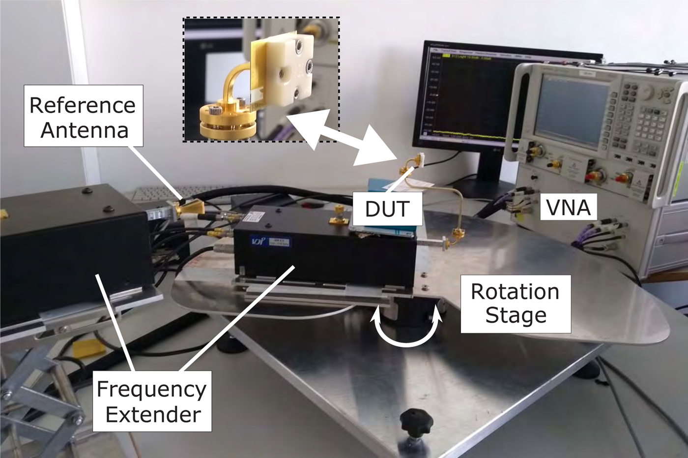
The measurement setup to characterize the antenna radiation pattern is presented in Fig. 6. A horn antenna with a gain of 24 dBi is used as reference antenna. Previous measurements have been performed to determine the insertion loss due to the rectangular waveguide sections and the transition from rectangular waveguide to SIW as presented in Fig. 4(b). The measured gain is corrected with these results. The measured gain and radiation pattern are in good agreement with the numerical results. The measured and corrected gain for antenna 1 in Fig. 3(a) is close to the simulated value of 5.54 dBi at 122.5 GHz. The measured gain in Fig. 3(b) for antenna 2 of 7.14 dBi is larger than the gain of antenna 1 but not as high as expected from the simulations. Additional losses in the section of the extended substrate are assumed to cause this deviation. The measured results of the radiation pattern are consistent with the simulations and show the desired radiation behavior over the whole frequency range from 120 to 125 GHz. Both antennas provide low side lobe levels in the azimuth plane. The extended substrate of antenna 2 results in a smaller beamwidth in the elevation plane.
Measurement setup for the characterization of the radiation pattern and antenna gain.
Conclusion
In this work, two different designs of a compact low-cost SIW fed antenna for the 122 GHz ISM band have been presented. The antennas are formed in a single RO4350B laminate. A gain of around 5.4 dBi was measured for the first antenna and could be optimized to 7.14 dBi for the second version by extending the substrate in front of the Vivaldi structure. The measured radiation pattern are in good agreement with the numerical results and show good focusing for a single element antenna. It could be successfully demonstrated that the RO4350B substrate can reasonably be used above 120 GHz for low-cost designs.
Author ORCIDs
Martin Frank, 0000-0001-9640-4277
Acknowledgments
This work has been developed in the project NetGuard6P. NetGuard6P (reference number: 16ES0183) is funded by the German ministry of education and research (BMBF) within the research program InPro3D.
 Martin Frank received the B.Sc. and M.Sc. degrees in electrical, electronics, and communication engineering from the Friedrich-Alexander University Erlangen-Nuremberg (FAU), Erlangen, Germany, in 2012 and 2015, respectively. In 2015, he joined the Institute for Electronics Engineering, FAU, as a Research Assistant. His current research interests include the areas of microwave circuits and antenna design for radar applications.
 Fabian Lurz received the B.Sc. and M.Sc. degrees in information and communication technology from the Friedrich-Alexander University Erlangen-Nuremberg (FAU), Erlangen, Germany, in 2010 and 2013, respectively. In 2013, he joined the Institute for Electronics Engineering, FAU, as a Research Assistant. He became the Group Leader of the Electronic Systems Group in 2017. His current research interests include microwave circuits and system, especially for low-cost and low-power metrology applications.
 Robert Weigel received the Dr.-Ing. and the Dr.-Ing. habil. degrees, both in electrical engineering and computer science, from the Munich University of Technology in Germany where he respectively was a Research Engineer, a Senior Research Engineer, and a Professor for RF Circuits and Systems until 1996. From 1996 to 2002, he has been Director of the Institute for Communications and Information Engineering at the University of Linz, Austria where, in August 1999, he cofounded the company DICE, devoted to the design of RFICs for mobile radio and MMICs for vehicular radar applications. Since 2002, he is Head of the Institute for Electronics Engineering at the University of ErlangenNuremberg, Germany. Prof. Weigel has been engaged in research and development of microwave theory and techniques, electronic circuits and systems, and communication and sensing systems. In these fields, he has published more than 900 papers.
 Alexander Koelpin received his diploma in electrical engineering in 2005, his doctoral degree in 2010, and his “venia legendi” in 2014 all with the University of Erlangen-Nuremberg (FAU), Germany. From 2005 to 05/2017, he was with the Institute for Electronics Engineering, FAU, Germany. From 2007 to 2010, he has been team leader; from 2010 to 2015, group leader Circuits, Systems and Hardware Test; and since 2015, leader of the group Electronic Systems. Since 06/2017, he isa Professor and Head of the Chair for Electronics and Sensor Systems with the Brandenburg University of Technology Cottbus-Senftenberg, Germany. His research interests are in the areas of microwave circuits and systems, wireless communication systems, local positioning, and six-port technology. He has authored or co-authored more than 200 publications in his areas of interest.


 Open access