


Introduction
Clinical hyperthermia, heating a tumor to 40–45°C for 1 h, is a cancer treatment applied in combination with chemotherapy and/or radiotherapy, with the aim to enhance the effectiveness of the latter two therapies [Reference Sapareto and Dewey1, Reference Oei, Kok, Oei, Horsman, Stalpers, Franken and Crezee2]. Clinical results are very good, and adding hyperthermia typically yields an increase in tumor response on the order of 15–20% [Reference Cihoric, Tsikkinis, van Rhoon, Crezee, Aebersold, Bodis, Beck, Nadobny, Budach, Wust and Ghadjar3, Reference Datta, Gomez Ordonez, Gaipl, Paulides, Crezee, Gellermann, Marder, Puric and Bodis4]. Realizing a sufficiently high tumor temperature is important as treatment outcome is correlated with the achieved tumor temperature [Reference Wust, Rau, Gellerman, Pegios, Loffel, Riess, Felix and Schlag5–Reference Bakker, Van der Zee, Van Tienhoven, Kok, Rasch and Crezee8]. Hyperthermia is tumor-selective if given sequentially, shortly before or after radiotherapy. In that case normal tissue temperatures of 40–45°C are well tolerated and do not lead to an increase in radiotherapy- or chemotherapy-related side-effects in the surrounding normal tissue. Temperatures exceeding 45°C should be avoided as these can lead to pain and normal tissue damage [Reference Bakker, Kolff, Holman, van Leeuwen, Korshuize-van Straten, Oldenhof-de Kroon, Rasch, van Tienhoven and Crezee9].
Superficial malignancies, such as chest wall recurrences of breast cancer or melanoma, extend less than 4 cm from the skin surface [Reference Dobšíček Trefná, Crezee, Schmidt, Marder, Lamprecht, Ehmann, Hartmann, Nadobny, Gellermann, van Holthe, Ghadjar, Lomax, Abdel-Rahman, Bert, Bakker, Hurwitz, Diederich, Stauffer and van Rhoon10] and are generally treated with MW antennas placed onto the lesion. The 915 MHz antennas of the BSD-500 system [Reference Chou11–Reference Müller, Hartmann and Bert13] and the 434 MHz microstrip applicators of the ALBA-4000 system [Reference Gelvich, Kolmakov, Kudryavtsev and Mazokhin14–Reference Kok, Correia, de Greef, van Stam, Bel and Crezee19] are the applicators used in the present clinically available superficial systems. Deep-seated malignancies, such as cervix, prostate, bladder, and rectum tumors, are usually heated with a phased array of RF antennas, organized in one or multiple rings around the pelvis of the patient [Reference Bruggmoser, Bauchowitz, Canters, Crezee, Ehmann, Gellermann, Lamprecht, Lomax, Messmer, Ott, Abdel-Rahman, Schmidt, Sauer, Thrall, Wessalowski and van Rhoon20, Reference Kok, Navarro, Strigari, Cavagnaro and Crezee21]. Clinical locoregional devices include the AMC-4 system [Reference van Dijk, Schneider, van Os, Blank and Gonzalez22], AMC-8 system [Reference Crezee, Van Haaren, Westendorp, De Greef, Kok, Wiersma, Van Stam, Sijbrands, Zum Vörde Sive Vörding, Van Dijk, Hulshof and Bel23], ALBA-4D system [Reference Zweije, Kok, Bakker, Bel and Crezee24], and BSD-2000 series [Reference Turner, Tumeh and Schaefermeyer25, Reference Wust, Seebass, Nadobny, Deuflhard, Monich and Felix26], which all operate at frequencies between 70 and 150 MHz. These phased array systems provide spatial steering of the energy deposition [Reference Kok, Navarro, Strigari, Cavagnaro and Crezee21, Reference Crezee, Van Haaren, Westendorp, De Greef, Kok, Wiersma, Van Stam, Sijbrands, Zum Vörde Sive Vörding, Van Dijk, Hulshof and Bel23], which proved instrumental in achieving good and therapeutic temperatures and good clinical results in a range of tumor sites including rectum, bladder, cervix, and soft-tissue sarcoma [Reference Rau, Wust, Hohenberger, Loffel, Hunerbein, Below, Gellermann, Speidel, Vogl, Riess, Felix and Schlag27–Reference Issels, Lindner, Verweij, Wessalowski, Reichardt, Wust, Ghadjar, Hohenberger, Angele, Salat, Vujaskovic, Daugaard, Mella, Mansmann, Dürr, Knösel, Abdel-Rahman, Schmid, Hiddemann, Jauch, Belka and Gronchi31].
However, not all tumor sites can be optimally heated with the commercially available devices listed in the previous paragraph. This paper reports on the development of three novel dedicated RF-based hyperthermia systems capable of delivering hyperthermia to three different challenging semi-deep-seated tumor sites: the leg, the breast, and the upper thorax (Fig. 1). Each system design is described, including clinical tumor temperature measurement methods, followed by examples of the actual clinical application.
The three dedicated systems presented in this paper. (a) Double-waveguide set-up for leg tumors with open water bolus. (b) Single-waveguide set-up with open water bolus for deep-seated breast tumors. (c) Double-waveguide set-up for tumors in the upper thorax, which uses three different aperture sizes. (d) Dominant field component Ez indicated by the blue arrow.

Methods
All systems are intended for deep/semi-deep-seated tumors, extending more than 4 cm from the skin surface. Therefore, we use the 70 MHz waveguides designed for the AMC-4, AMC-8, and ALBA-4D systems used at our department, as these have a 50% larger penetration depth than 434 MHz antennas [Reference van Wieringen, Wiersma, Zum Vorde Sive Vording, Oldenborg, Gelvich, Mazokhin, van Dijk and Crezee32]. The water-filled waveguides have a length of 12 cm (¼λ), apertures of 34 × 21 cm, 34 × 15 cm, or 34 × 8.5 cm, and effective penetration depths of 3.5, 3.1, and 2.7 cm, respectively (Fig. 1(d)) [Reference van Stam, Kok, Hulshof, Kolff, Van Tienhoven, Sijbrands, Bakker, Schoorl, Zum Vorde Sive Vording, Oldenborg, De Greef, Rasch and Crezee33]. The effective penetration depth is the depth at which specific absorption rate (SAR) is 50% of the value at 1 cm depth, as defined in the European Society of Hyperthermia (ESHO) Quality Assurance (QA) guidelines [Reference Dobšíček Trefná, Crezee, Schmidt, Marder, Lamprecht, Ehmann, Hartmann, Nadobny, Gellermann, van Holthe, Ghadjar, Lomax, Abdel-Rahman, Bert, Bakker, Hurwitz, Diederich, Stauffer and van Rhoon10, Reference Hand, Lagendijk, Bach Andersen and Bolomey34].
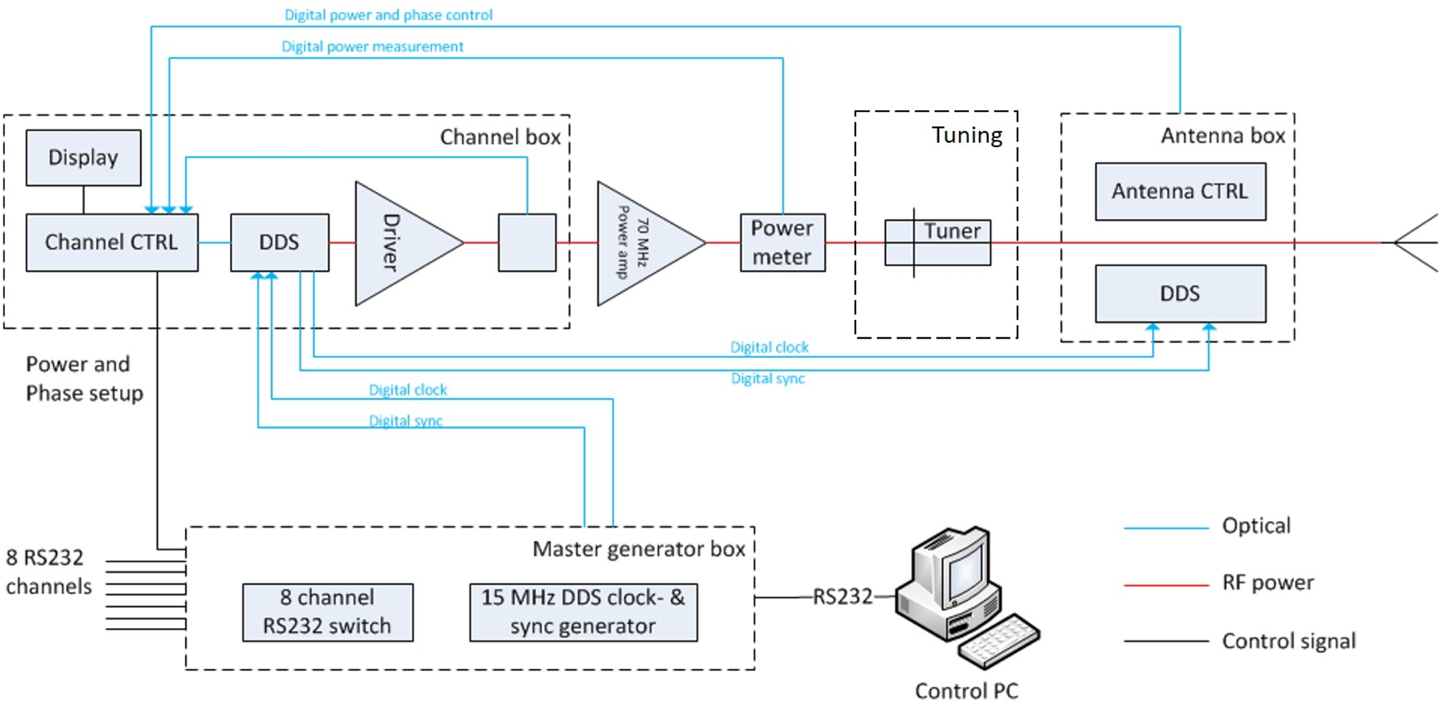
The 70 MHz generator system of the AMC-8 system shown in Fig. 2 is used [Reference Crezee, Van Haaren, Westendorp, De Greef, Kok, Wiersma, Van Stam, Sijbrands, Zum Vörde Sive Vörding, Van Dijk, Hulshof and Bel23]. This is an eight channel DDS-based phase and amplitude controlled RF generator system with a phase accuracy of 3° and an output power accuracy of 10 W (SSB Electronic, Iserlohn, Germany). A double-slug tuner is placed between the 70 MHz power amplifier and the antenna. This tuner is used for tuning of each channel. The solid state amplifiers used (Restek, Rome, Italy) provide 500 W maximum output power for each channel.
The eight channel DDS phase and amplitude controlled 70 MHz generator system used for all three systems shown in Fig. 1. Each channel has a tuner and 500 W maximum output power [Reference Crezee, Van Haaren, Westendorp, De Greef, Kok, Wiersma, Van Stam, Sijbrands, Zum Vörde Sive Vörding, Van Dijk, Hulshof and Bel23].
Two systems presented in this paper use the principle of a phased antenna array and phase steering. This principle is also applied for instance in the AMC4 and ALBA4D phased array systems for pelvic and abdominal tumors, which both use a ring of four waveguides positioned around the patient as shown in Fig. 3 [Reference van Dijk, Schneider, van Os, Blank and Gonzalez22, Reference Zweije, Kok, Bakker, Bel and Crezee24]. The four waveguides operate in the TE10 mode and are positioned in such a way that the dominant E-field component Ez of each antenna is parallel to the longitudinal axis of the body. Thus, the Ez(i) contributions of each waveguide i add up, which allows to realize a central E-field focus at the tumor, with a local power deposition expressed as SAR in W/kg proportional to the square of the total E-field:

Principle of phased array systems. (a) Four antenna ALBA4D system. (b) A central E-field focus can be realized by superposition of the Ez(i) of antennas 1 through 4 parallel to the longitudinal axis of the patient body in the ALBA4D system.

Phase steering of the four waveguides is utilized to position the E-field focus onto the desired tumor target location [Reference van Dijk, Schneider, van Os, Blank and Gonzalez22, Reference Zweije, Kok, Bakker, Bel and Crezee24]. Similar phase steering principles are applied in the two double-waveguide dedicated systems for the leg and upper thorax described in this paper. The optimal phase difference between the two waveguides yielding best focalization onto the tumor is established by performing a ΔT test. This involves measuring at the start of each clinical treatment the temperature rise ΔT in the tumor after 60 s of power on, and comparing the resulting ΔT for three different phase settings, e.g. −40°, 0°, and +40°. The phase setting yielding the best temperature increase in the tumor will be selected [Reference Kok, Ciampa, de Kroon-Oldenhof, Steggerda-Carvalho, van Stam, Zum Vorde Sive Vording, Stalpers, Geijsen, Bardati, Bel and Crezee35].
A water bolus is positioned between the antennas and the patient to ensure that the electromagnetic energy emitted by the antennas is coupled effectively into the patient, and to provide either warming or cooling of the skin to ensure that the entire tumor is heated to the therapeutic temperature range. This water bolus is either a plastic bag containing distilled water (system 1C is an example) or an open tank with tap water or distilled water (as used for systems 1A and 1B). The open tank is used to optimize energy coupling to irregularly shaped body surfaces. Distilled water has the advantage of negligible power loss in the water bolus, ensuring optimal energy transfer to the tumor.
Tumor and skin temperature measurements are performed using multi-sensor copper constantan thermocouple probes (ELLA-CS, Hradec Králové, Czech Republic) placed in catheters inserted in the tumor. An in-house developed 196 channel thermometry system is used to measure undisturbed tumor temperatures during brief power-off intervals. Tumor temperatures during treatment are reported as T10, T50, and T90, i.e. the temperature at least achieved in 10, 50, and 90% of the tumor during the 1 h steady state period of the treatment. Invasive normal tissue temperature measurements are clinically nearly impossible for ethical reasons. Incidence of normal tissue hot spots is therefore generally monitored by responding to patient complaints, which occur when a pain threshold of 45°C is exceeded [Reference Bakker, Kolff, Holman, van Leeuwen, Korshuize-van Straten, Oldenhof-de Kroon, Rasch, van Tienhoven and Crezee9].
All treatments in this paper combined hyperthermia with radiotherapy, typically in a hypo-fractionated schedule of 8 × 4 Gy as shown in Fig. 4, with radiotherapy given twice a week and once a week the radiotherapy fraction was followed by 1 h of hyperthermia with a time interval of 1 h or less between the two treatments to achieve maximum thermal sensitization of the effectiveness of radiotherapy by the addition of hyperthermia [Reference Van Leeuwen, Oei, Chin, Crezee, Bel, Franken, Stalpers and Kok36].
Hypofractionated 8 × 4 Gy schedule giving radiotherapy twice a week, once a week hyperthermia is performed, ~1 h after the radiotherapy fraction.

Hyperthermia of a leg
The leg system consisted of two opposing waveguides with an aperture of 34 × 21 cm placed on either side of the leg immersed in an open, temperature-controlled water bolus. The open water bolus serves to optimize coupling of energy into the leg without inducing local hot spots in the skin (Figs 1(a) and 5). The waveguides operate in the TE10 mode and are placed with the long side in the axial direction of the leg to cover a ~35 cm section of the leg. The dominant E-field component Ez is thus perpendicular to the longitudinal axis of the leg (Figs 1(a) and 5). Phase steering of the two waveguides is utilized to move the E-field focus onto the tumor target location. The water bolus temperature is set to fairly high values (~40°C) as the tumors in the leg generally already start quite close to the skin surface; low water temperatures would lower the tumor temperature near the skin. More technical details can be found in [Reference Kok, de Greef, van Wieringen, Correia, Hulshof, Zum Vorde Sive Vording, Sijbrands, Bel and Crezee37].
System 1A: antenna set-up and skin temperatures during hyperthermia treatment of melanoma lesions on a leg, power switched on at t = 6 and t = 16 min.

Hyperthermia of an intact breast
This set-up uses an open water bolus into which the breast is hanging to ensure optimal coupling of energy into the breast without inducing local hot spots in the skin. Heating is achieved using a single waveguide with an aperture of 34 × 21 cm placed at the bottom of a temperature-controlled water bath (Fig. 1(b)). The waveguide aperture orientation is with its long side in the axial direction of the patient. To avoid unwanted field deposition in the non-tumor breast, the skin of that breast is covered with a water-tight cloth to prevent any SAR deposition in the healthy breast.
The water temperature is in the higher temperature range (~40–43°C) as the skin of the breast is part of the tumor target volume. Thermocouple temperature probes are placed onto the skin and invasively in the tumor (Fig. 6). Prior to treatment both tap water and distilled water have been tested. Tap water leads to significant absorption in the water bolus, and requires relatively high power to ensure sufficient SAR in the tumor. We did choose tap water for hygiene, as distilled water required continuous recirculation of water. For details see [Reference Crezee, Van Tienhoven, Kolff, Sijbrands, Van Stam, Oldenborg, Geijsen, Hulshof and Kok38].
System 1B: location of lateral (l) and cranio-caudal (c-c) invasive thermometry probes during hyperthermia. Right: position of the breast in the open water bolus.

Hyperthermia of semi-deep-seated tumors in the thorax
This system consists of two waveguides operating in the TE10 mode; these are placed to the ventral and dorsal side of the thorax. The set-up shown in Fig. 1(c) has a dominant E-field component along the longitudinal axis of the body, similar to the orientation in the four waveguide phased array used for heating pelvic and abdominal tumors (Fig. 3). The two waveguide system allows both waveguides to rotate to accommodate the optimal position in view of the actual anatomical location (Fig. 7). Phase steering is utilized to move the E-field focus onto the tumor target location. The dorsal waveguide is always the largest size with an aperture of 21 × 34 cm, the ventral waveguide is selected based on the exact anatomical site. Locations close to the head generally require the use of the smaller-sized waveguide models to ensure sufficient distance to the head of the patient. Thermocouple temperature probes are placed invasively in the tumor (Fig. 11). The water bolus temperature can range between room temperature (~21°C) and 43°C and can be set separately for each waveguide. This temperature is selected based on the tumor location. More details can be found in [Reference van Stam, Kok, Hulshof, Kolff, Van Tienhoven, Sijbrands, Bakker, Schoorl, Zum Vorde Sive Vording, Oldenborg, De Greef, Rasch and Crezee33].
System 1C: placement and rotation of the ventral 70 MHz waveguide on the thorax. Blue arrows indicate dominant E-field direction for different antenna directions.

Results
Hyperthermia of a leg
Figure 5 shows patient set-up and temperature results for a patient with multiple large melanoma on his leg. The patient is treated in sitting position with the leg immersed in the double-waveguide hyperthermia system. All treatment sessions were performed with both waveguides operating at the same amplitude and with a 0° phase difference. High power (400 W) in combination with a low water temperature of 39.5°C resulted in better median temperatures exceeding 40°C, than high water temperature (42°C) and low power (200 W). The treatment was tolerated with no hot-spot-related pain complaints. At 7 weeks after treatment, the sizes of the largest tumor volume had decreased significantly and necrotic regions in the tumor were observed (Fig. 8). Therefore, local tumor control was achieved, but unfortunately the disease progressed outside the leg.
System 1A: regression and necrotization of melanoma on the lower leg 7 weeks after the last hyperthermia session, as compared to the status in the third week of treatment.

Hyperthermia of an intact breast
A series of six consecutive breast cancer patients were treated with the single 70 MHz waveguide breast applicator, with each patient receiving a total of 4 weekly sessions. Figure 6 shows a computerized tomography (CT) image with the tumor location for one of our patients, along with an image of the breast immersed in the open water bolus during treatment. The water temperature was ~42°C and power was relatively high due to the use of tap water, and ranged between 300 W in the first patient and 925 W in the last patient. Treatment was well tolerated by all patients, no pain complaints due to SAR-related hot spots occurred, not even at 925 W. This can probably be attributed to the use of the open water bolus, combined with the effective heat removal by the high blood flow in the superficial vessels in the skin of the breast, which is greatly enhanced in response to the hyperthermic conditions.
The invasive tumor temperatures measured during the 1 h steady-state period of treatment averaged over all six patients and all four sessions per patient were T90 = 39.9°C, T50 = 41.2°C, and T10 = 42.3°C (Fig. 9).
System 1B: average tumor temperatures T10, T50, and T90 for six breast cancer patients.

An example of typical temperature profiles during treatment shows that the skin temperature is fairly uniform at ~42.5°C, and fairly high and uniform invasive tumor temperatures between 41.5 and 42°C are achieved at maximum depth in the central target zone (Fig. 10).

Hyperthermia of semi-deep-seated tumors in the thorax
Figure 11 shows a CT with the tumor site and temperature probe for one of our first patients with a supraclavicular tumor in the upper thorax, along with an image of the placement of the 70 MHz waveguide at the ventral side. The dorsal waveguide embedded in the table top is not visible. Both waveguides had an aperture size of 21 × 34 cm. The treatment series started with two sessions using only the ventral waveguide, followed by two sessions during which both waveguides were used. Output power was set at 100 and 250 W for the ventral and dorsal waveguides, respectively, this was based on patient tolerance for output power for each waveguide. The temperature in the water bolus was ~30°C for both waveguides to cool the skin moderately, and the resulting median tumor temperature T50 was ~39°C in the first sessions using one waveguide, increasing to ~44°C in the later sessions using both waveguides. Even the lower tumor temperature T90 exceeded 41°C in the last two sessions, indicating the entire tumor had reached therapeutic temperature levels (Fig. 12).
System 1C: location of the temperature probe and position of the ventral waveguide for a patient with a supraclavicular tumor in the upper thorax.

System 1C: applied power and tumor temperature during treatment of the deep-seated supraclavicular tumor shown in Fig. 8. Sessions 1 + 2: ventral waveguide is used, sessions 3 + 4: both ventral and dorsal waveguides are used.

We presently treat 20–25 patients per year with this device. Patient tolerance varies, sometimes pain complaints occur due to unwanted hot spots close to bony structures. These are normally resolved by rotating the two waveguides to another angle to avoid the dominant Ez field component to point straight into bony structures, or by altering the power balance between dorsal and ventral waveguides to alleviate the pain complaint. More eccentric locations can pose issues with excessive water accumulation in the section of the water bag of the ventral waveguide extending outside the body. This can usually be resolved by modifying the shape of the water bag.
Conclusion
Clinical experience with heating of deep-seated pelvic tumors using phased array systems of RF antennas is based on large patient series around the globe starting already in the 1980s. We have demonstrated in this paper that the basic principles of this technology can be used to treat also more challenging deep-seated and semi-deep-seated tumor locations elsewhere in the body, presenting three dedicated systems for the intact breast, the upper thorax, and the limbs. We should also mention the development of dedicated phased array systems by other research groups, using 140 MHz antennas for breast lesions [Reference Wu, McGough, Arabe and Samulski39], and 434 MHz antennas for head and neck tumors [Reference Paulides, Bakker, Neufeld, van der Zee, Jansen, Levendag and van Rhoon40, Reference Dobsicek Trefna, Vrba and Persson41]. The relatively low frequency of 70 MHz we have been using has as potential disadvantage that the focal volume is relatively large, but also a major advantage that the penetration depth is better than at higher frequencies. This resulted in adequate therapeutic temperatures in most of our patients, a good achievement in view of the fact that all presented systems used just one or two waveguides to achieve heating at depth. Another favorable feature is the stable phase control, which can also be partly be attributed to the use of robust waveguide technology. Arrays of other types of antennas can display crosstalk between antennas, this form of mutual interaction can cause unwanted and large phase shifts which can result in suboptimal focalization of the tumor target region [Reference Wust, Fähling, Wlodarczyk, Seebass, Gellermann, Deuflhard and Nadobny42, Reference Kongsli, Hjertaker and Frøystein43].
The tumor temperatures we achieved are in fact in a similar therapeutic range as the temperatures achieved in pelvic tumors using phased array systems with larger numbers of antennas. This is very important in view of the strong dose–effect relationship found for many tumors, e.g. as found in a recent review for recurrent breast cancer treated mainly with 434 MHz applicators [Reference Bakker, Van der Zee, Van Tienhoven, Kok, Rasch and Crezee8] and for cervical tumors treated with phased array systems of RF antennas in Rotterdam [Reference Franckena, Fatehi, de Bruijne, Canters, van Norden, Mens, van Rhoon and van der Zee6, Reference Kroesen, Mulder, Van Holthe, Aangeenbrug, Mens, Van Doorn, Paulides, Oomen-de Hoop, Vernhout, Lutgens, Van Rhoon and Franckena7] and in Amsterdam [Reference Van Leeuwen, Oei, Chin, Crezee, Bel, Franken, Stalpers and Kok36].
The next step is to promote more wide clinical use of these solutions for challenging locations. This will require convincing manufacturers to include these solutions as an add-on with their phased array systems for deep-seated pelvic tumors.
Acknowledgement
This work was supported by the Dutch Cancer Society KWF, grant UVA 2017-10873.
 Johannes Crezee received his M.Sc. degree in experimental physics from the Free University Amsterdam in 1986, and his Ph.D. degree from Utrecht University in 1993. From 1988 to 2000, he was with the University Medical Center, Utrecht, engaged on several hyperthermia projects, including treatment planning and development of interstitial hyperthermia methods. Since 2000, he has been with the Department of Radiation Oncology, Academic Medical Center (AMC), Amsterdam (now Amsterdam University Medical Centers), as a Principal Investigator with a special interest in hyperthermia research, focusing on the development of new hyperthermia equipment and on hyperthermia treatment planning. He is currently a project leader on research projects at the Amsterdam UMC supported by grants of the Dutch Cancer Society (KWF), including the application of adaptive treatment planning, planning for irreversible electroporation (IRE), and for hyperthermic intraperitoneal perfusion (HIPEC) and a project on the use of MRI for hyperthermia treatment planning.
 Remko Zweije received his B.Sc. in electrical engineering from the Hogeschool Enschede University of applied sciences in 1996 and his B.Ed. from the HU University of applied sciences Utrecht in 2013. He has been working as a development and software engineer and science teacher until 2015. Since 2015 he is working as an engineer at the hyperthermia group of the Department of Radiation Oncology of the Amsterdam University Medical Centers.
 Jan Sijbrands works as a mechanical engineer at the Department of Radiation Oncology of the Amsterdam University Medical Centers in Amsterdam.
 H. Petra Kok received her M.Sc. degree in computational science from Utrecht University in 2002. Thereafter, she worked as a Ph.D. student at the Department of Radiation Oncology of the Academic Medical Center (AMC) in Amsterdam on a project to develop dual modality heating technique for hyperthermia treatment of esophageal cancer. She received her Ph.D. from the University of Amsterdam in 2007 and continued as a post-doc at the AMC on optimization of locoregional hyperthermia delivery. Her research was awarded five young investigator awards and an Editor's Award of the International Journal of Hyperthermia. Currently, she works at the Department of Radiation Oncology of Amsterdam University Medical Centers as a project leader and senior researcher on advanced hyperthermia treatment planning models, including adaptive hyperthermia planning and biological thermoradiotherapy planning to model the effect of combined radiotherapy and hyperthermia, her research is supported by grants of the Dutch Cancer Society (KWF).


 Open access