


1. Introduction
Unsteady dynamics of leading edge vortices (LEVs) has a considerable influence on the operation of bio-inspired robotic swimmers and micro underwater vehicles (Mueller & DeLaurier Reference Mueller and DeLaurier2003). Spanwise instability of LEVs promotes the growth of secondary hairpin-like structures that eventually lead to wake three-dimensionality (Verma, Khalid & Hemmati Reference Verma, Khalid and Hemmati2023). Understanding mechanisms of the spatio-temporal dynamics of such instabilities is important, since they directly influence the force and rolling moments generated on the lifting surface of wings, for example (Chiereghin et al. Reference Chiereghin, Bull, Cleaver and Gursul2020). As the LEVs advect along the oscillating body, spatio-temporal changes in vortex instability impose variations in aerodynamic and hydrodynamic moments. This directly impacts the vibration and structural integrity of the body (Bull et al. Reference Bull, Chiereghin, Gursul and Cleaver2021). This also includes aspects of controllability, which is crucial in the case of small-scale micro air vehicles and autonomous underwater vehicles that warrant rapid response from the control systems (Visbal Reference Visbal2012). Disintegration of vortex structures in the wake of oscillating foils also holds importance for understanding mechanisms that can reduce noise generation. This is observed during motion of helicopter rotor and wind turbine blades, where their high frequency flutter closely resembles an oscillatory motion of a solid body (Wang, Zhao & Wu Reference Wang, Zhao and Wu2015). In certain conditions, undesirable effects of dynamic stall and noise can be prevented by artificially imposing oscillations that promote growth of vortex instability and its faster disintegration (Zurman-Nasution, Ganapathisubramani & Weymouth Reference Zurman-Nasution, Ganapathisubramani and Weymouth2020; Talboys et al. Reference Talboys, Geyer, Prüfer and Brücker2021). Instability characterization also helps in establishing an association between unsteady vortex dynamics and propulsive performance of swimming mammals (Deng & Caulfield Reference Deng and Caulfield2015; Deng et al. Reference Deng, Sun, Lubao, Pan and Shao2016; Sun, Deng & Shao Reference Sun, Deng and Shao2018; Verma & Hemmati Reference Verma and Hemmati2021). Recently, transition of spanwise instability of LEVs to secondary hairpin-like structures is also reported for flows over biological oscillating fins of batoids (Zhang & Huang Reference Zhang and Huang2023). This study revealed the development of spanwise corrugations on LEVs, which subsequently curl into streamwise vorticity filaments. These filaments, under increased strain fields of vortex cores, are stretched to form one-legged hairpin structures (Zhang & Huang Reference Zhang and Huang2023). The pectoral fin experienced a stronger and faster LEV deformation, ultimately contributing to the formation of hairpin-like vortex arrangement. This was due to its higher amplitude compared to the rest of the body. Verma & Hemmati (Reference Verma and Hemmati2023) provided elaborate description of the evolution features of secondary instabilities and intermediate secondary hairpin-like structures at phase-offset  $90^\circ \le \phi \le 270^\circ$ and Strouhal number $St_c = 0.32$. This study extends the findings of Verma & Hemmati (Reference Verma and Hemmati2023) by assessing the influence of varying $St_c$ on the transition in primary LEV instability and subsequent transformation to secondary hairpin-like structures.
Elliptic instability has been linked primarily to pairs of spanwise coherent structures, known as rollers, rotating in counter directions with either equal or unequal strength (Leweke & Williamson Reference Leweke and Williamson1998; Ortega & Savas Reference Ortega and Savas2001; Leweke, Le Dizès & Williamson Reference Leweke, Le Dizès and Williamson2016). Both experimental and numerical investigations modelling such instabilities have concentrated on isolated pairs of vortices. In these studies, temporal evolution of the spatial dislocations on the rollers has been observed clearly (Leweke & Williamson Reference Leweke and Williamson1998; Bristol et al. Reference Bristol, Ortega, Marcus and Savas2004). Ortega, Bristol & Savas (Reference Ortega, Bristol and Savas2003) conducted a stability analysis on paired vortices, and provided a quantitative assessment involving circulation, internal strain field distribution, and evolution mechanisms of sinusoidal instability. These revealed a spatial wavelength of lower magnitude compared to Crow's estimation for an equal-strength vortex pair (Crow Reference Crow1970). Bristol et al. (Reference Bristol, Ortega, Marcus and Savas2004) extended existing analysis to a co-rotating vortex pair, illustrating the formation of vorticity bridges due to elliptic instability, contributing to vortex merger in the wake. Meunier & Leweke (Reference Meunier and Leweke2005) also revealed that Crow's linear stability model effectively characterizes the behaviour of equal-strength counter-rotating vortex pairs, showing that the early growth phase of instability aligns with vortex pair merger at specific spanwise intervals, resulting in a vortex ring-like arrangement.
In addition to the foundational investigations on spanwise instabilities of isolated vortex pairs, their impact on the wake three-dimensionality has been noted previously in the context of stationary bluff bodies. Examples include a circular cylinder (Barkley & Henderson Reference Barkley and Henderson1996; Brede, Eckelmann & Rockwell Reference Brede, Eckelmann and Rockwell1996; Williamson Reference Williamson1996) and a blunt trailing edge aerofoil (Ryan, Thompson & Hourigan Reference Ryan, Thompson and Hourigan2005; Gibeau, Koch & Ghaemi Reference Gibeau, Koch and Ghaemi2018). Experimental visualizations have indicated that the development of streamwise coherent structures, referred to as ribs, is linked to spanwise instability modes exhibiting distinct spatio-temporal characteristics (Williamson Reference Williamson1996). Mittal & Balachandar (Reference Mittal and Balachandar1995) emphasized the emergence of secondary hairpin-like configurations, which manifested as spatial dislocations along the spanwise rollers downstream of a stationary circular cylinder. Over time, these displaced formations extended and gave rise to rib pairs. Thus Mittal & Balachandar (Reference Mittal and Balachandar1995) and Williamson (Reference Williamson1996) conclusively affirmed the crucial role of intermediary structures in the formation of three-dimensional wake features.
Fluid dynamicists have broadened their examination of instability beyond stationary bluff bodies. This involves assessing instability in rigid bodies engaged in prescribed oscillations (Nazarinia et al. Reference Nazarinia, Lo Jacono, Thompson and Sheridan2009; Visbal Reference Visbal2009; Deng & Caulfield Reference Deng and Caulfield2015; Sun et al. Reference Sun, Deng and Shao2018). These studies delve into diverse facets of secondary wake structures, and elucidate their impact on three-dimensional characteristics of the wake. Visbal (Reference Visbal2009) emphasized a substantial influence of varying  $St_c$ on the behaviour of LEVs. Notably, higher $St_c$ values were observed to contribute towards significant deformations of the LEV, ultimately transitioning it into an arched vortex undulation pattern that was noted by Visbal (Reference Visbal2009) and Calderon et al. (Reference Calderon, Cleaver, Gursul and Wang2014). The presence of instability modes with varying wavelengths, both long and short, and the resulting arrangement of secondary vortices, were investigated on a pitching foil by Deng & Caulfield (Reference Deng and Caulfield2015). This revealed a direct correlation between the formation of secondary vortex pairs and the asymmetric arrangement of primary rollers shed behind the foil. Moriche, Flores & García-Villalba (Reference Moriche, Flores and García-Villalba2016) conducted stability analysis on a foil with combined heaving and pitching motion, which provided insights into the three-dimensional wake transition and its impact on aerodynamic forces. Although there were minimal effects on forces, simulations revealed that the onset of three-dimensionality for the wake of infinite-span oscillating wings was associated with the bending of the trailing edge vortex (TEV) (Moriche et al. Reference Moriche, Flores and García-Villalba2016). Oscillating foils governed by both pitching and heaving motion also present a better performance in energy harvesting systems (Kim et al. Reference Kim, Strom, Mandre and Breuer2017). For a purely heaving motion, the LEV can possibly separate from the foil boundary, which subsequently coincides with a sudden drop in lift force. To counter this, a pitching motion can be added to the foil that rotates it effectively to produce another LEV. This balances the power loss resulting from the separation of the LEV in the previous half shedding cycle. Such benefits have also been confirmed for biological locomotion of animals (Kim et al. Reference Kim, Strom, Mandre and Breuer2017).
Chiereghin et al. (Reference Chiereghin, Bull, Cleaver and Gursul2020) identified sinusoidal undulation on the shed LEV filament in the wake of a high aspect ratio heaving swept wing. The origins of these undulations remained unclear, speculated to be an instability of oscillating shear flow, the mixing layer, or the vortex filament itself. Additionally, Chiereghin et al. (Reference Chiereghin, Bull, Cleaver and Gursul2020) noted that increasing circulation of LEVs at high reduced frequencies ( $k$) resulted in stronger deformations, coinciding with significant effects on lift and bending moments. Verma & Hemmati (Reference Verma and Hemmati2021) highlighted the prevalence of elliptic-type short-wavelength instability in highly propulsive wake flows, as discussed originally by Leweke & Williamson (Reference Leweke and Williamson1998). Further evidence was also presented on the emergence of tongue-like dislocations on the primary rollers at low $St_c$. However, wakes associated with high $St_c$ and larger thrust generation exhibited interconnected hairpin–horseshoe structures (Verma & Hemmati Reference Verma and Hemmati2021). Quantitative analysis, which considered spanwise wavelength ( $\lambda _z$) and periodicity of streamwise vortex pairs or ribs, established a clear connection to the elliptic-type short-wavelength instability (Williamson Reference Williamson1996). In a recent study by Son et al. (Reference Son, Gao, Gursul, Cantwell, Wang and Sherwin2022), LEV instabilities were examined within the context of heaving oscillations that encompass both high aspect ratio wings and infinite-span foils. This study revealed changes in the strength of primary LEVs and TEVs in response to variations in $St_c$. These changes also coincided with alterations in the onset mechanisms of spanwise instability. The association of kinematics and spanwise instability was also observed across a range of chord-based $St_c$ and $\phi$ (Verma & Hemmati Reference Verma and Hemmati2023; Verma et al. Reference Verma, Khalid and Hemmati2023). In particular, Verma et al. (Reference Verma, Khalid and Hemmati2023) discussed the growth of secondary hairpin-like structures and their association to the spanwise instability of rollers for different regimes of oscillating foil kinematics. This study also confirmed that the onset of three-dimensionality, in the form of secondary hairpin-like growth, is governed not only by changes in $St_c$, but also by $\phi$. In particular, the interaction between primary and secondary LEVs can no longer govern the formation of secondary hairpin-like structures when $\phi$ increases from 90 $^\circ$ to 270 $^\circ$, at $St_c = 0.32$. Rather, primary LEV–TEV interaction led to either their growth at $\phi = 180^\circ$, or a complete absence at $\phi = 225^\circ$ and 270 $^\circ$. Despite thorough investigations on the wake dynamics behind oscillating foils, there remains an unexplored fundamental mechanism that elucidates a direct transition from spanwise LEV instability to secondary hairpin-like structures in the wake of oscillating foils. Our objective is to gain a comprehensive understanding of this transition mechanism as the kinematics of oscillating foils undergoes changes in terms of $St_c$.
2. Problem description
The flow around an infinite-span (two-dimensional) foil with maximum thickness ( $D$) to chord length ( $c$) ratio $D/c=0.1$ is examined numerically for a range of chord-based Strouhal numbers ( $St_{c} = fc/U_{\infty } = 0.32\unicode{x2013}0.56$) and amplitude-based Strouhal numbers ( $0.05 \le St_{A} \le 0.4$). Andersen et al. (Reference Andersen, Bohr, Schnipper and Walther2017) indicated that significant transitions in the wake of flapping foils were observable at
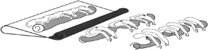
  $0.2 < St_{A} < 0.4$. This range also coincides with the optimal propulsive efficiency in swimming mammals (Triantafyllou et al. Reference Triantafyllou, Hover, Techet and Yue2005; Smits Reference Smits2019). The cross-section of the foil shown in figure 1 resembles a teardrop hydrofoil shape, which closely resembles the tailfin of a carangiform swimmer (Smits Reference Smits2019) and was used in recent experimental investigations (Floryan et al. Reference Floryan, Van Buren, Rowley and Smits2017; Van Buren, Floryan & Smits Reference Van Buren, Floryan and Smits2019). The Reynolds number is $Re = U_{\infty } c/\nu = 8000$, where $U_\infty$ and $\nu$ represent the freestream velocity and kinematic viscosity of the fluid, respectively. This choice of $Re$ agrees closely with the biological characteristics of some swimming fish (Anderson et al. Reference Anderson, Streitlien, Barrett and Triantafyllou1998; Smits Reference Smits2019; Verma & Hemmati Reference Verma and Hemmati2021). Williamson (Reference Williamson1996) mentioned that the shear layer transition regime lies at approximately $Re = 5300$, as also suggested by Zurman-Nasution et al. (Reference Zurman-Nasution, Ganapathisubramani and Weymouth2020). Since our $Re$ corresponds to 8000, we are well past the transition regime. Further, Verma & Hemmati (Reference Verma and Hemmati2023) and Verma et al. (Reference Verma, Khalid and Hemmati2023) reported a spanwise instability wavelength ( $\lambda _{z}$) of approximately 1 at $Re = 8000$, which is close to the long-wavelength instability identified in purely pitching (Deng & Caulfield Reference Deng and Caulfield2015) and heaving (Sun et al. Reference Sun, Deng and Shao2018) foils at $Re = 1800$. Even at $Re = 20\,000$, Chiereghin et al. (Reference Chiereghin, Bull, Cleaver and Gursul2020) observed a similar wavelength of spanwise instability for the case of a plunging foil. Overall, the variation of $Re$ within the range coinciding with biological swimming/flying might not offer a drastic change in the transition mechanism of spanwise instability discussed in our study.
Schematic of the foil geometry and motion.

The kinematics of the foil is prescribed by a coupled heaving and pitching motion, where the pitch axis is located at approximately 0.05 $c$ from the leading edge. Figure 1 marks the heave and pitch amplitudes as $h_o$ and $\theta _o$, respectively. The resultant trailing edge amplitude is also shown as $A_T$. The motion profiles of heave ( $h$) and pitch ( $\theta$), where pitching has a phase advancement (or offset) $\phi$ relative to heaving, are represented as $h(t)=h_{o} \sin (2 {\rm \pi}f t)$ and $\theta (t)=\theta _{o} \sin (2 {\rm \pi}f t+\phi )$, respectively.
In order to present a broader association of secondary hairpin-like structures and kinematics of the foil, we also vary the phase offset ( $\phi$) between heaving and pitching motion in the range 90 $^\circ$ to 270 $^\circ$. However, the discussion of results is focused at $\phi = 90^\circ$, in order to explore and characterize the transition of spanwise instability of primary LEVs with increasing $St_c$. Verma & Hemmati (Reference Verma and Hemmati2023) and Verma et al. (Reference Verma, Khalid and Hemmati2023) discussed findings at varying $\phi$ from 90 $^\circ$ to 270 $^\circ$. The findings suggests that the origin of a secondary hairpin-like structure encounters changes at $St_c = 0.32$. The heave-dominated kinematics at $\phi = 90^\circ$ is governed by an interaction between the primary and secondary LEVs over the foil boundary. However, at $\phi = 180^\circ$, the interaction of primary LEV–TEV promoted a cooperative elliptic instability on the TEV, which subsequently transformed to a secondary hairpin-like structure. With further increase in $\phi$ to 225 $^\circ$ and 270 $^\circ$, there was an absence of secondary hairpin-like generation. Later, Verma et al. (Reference Verma, Khalid and Hemmati2023) also confirmed that with increasing $St_c$, the wake systems showed a dominant primary and secondary LEV interaction that contributes to the growth of secondary hairpin-like structures. However, a transition of primary LEV instability has not been discussed in detail. This appeared dominant only at $\phi = 90^\circ$. Verma & Hemmati (Reference Verma and Hemmati2022a) further highlighted that the peak effective angle of attack ( $\alpha _{eff}$) is observed at $\phi = 90^\circ$, which implies a correspondence to strong three-dimensionality in LEVs (Chiereghin et al. Reference Chiereghin, Bull, Cleaver and Gursul2020). This substantiates our reasoning for depicting the results at $\phi = 90^\circ$, so that a novel and vivid mechanism can be laid out to explain the transition of LEV spanwise instability to secondary hairpin-like structures. Figure 2(a) shows the variation of $\alpha _{eff}$ at $\phi = 90^\circ$, while $St_c$ increases from 0.32 to 0.56. Moreover, peak $\alpha _{eff}$ increases as $St_c$ varies in this range. The peak magnitude coincides with $t^+ = 0.5$. Figure 2(b) provides a variation of $\alpha _{eff}$ at different $\phi$ in the range $90^\circ \le \phi \le 270^\circ$ for the case $St_c = 0.32$. The peak $\alpha _{eff}$ coincides with $\phi = 90^\circ$, which decreases with increasing $\phi$ towards 270 $^\circ$. The observations are consistent with discussion presented by Verma & Hemmati (Reference Verma and Hemmati2022a), where the variation also demonstrates a transition of kinematics from heave domination to an onset of pitch domination. The greater $\alpha _{eff}$ observed at $\phi = 90^\circ$ supports the discussion that the LEV three-dimensionality is expected to be the strongest within the range considered here.
Variation of  $\alpha _{eff}$ within one oscillation period at (a) increasing $St_c$ and $\phi = 90^\circ$, and (b) increasing $\phi$ and $St_c = 0.32$.

2.1. Computational method
The continuity and Navier–Stokes equations are solved directly using OpenFOAM, which is a numerical package based on the finite-volume method. This platform is used extensively for simulating wake dynamics behind oscillating foils and panels (Senturk & Smits Reference Senturk and Smits2019; Verma & Hemmati Reference Verma and Hemmati2021, Reference Verma and Hemmati2022b; Verma, Freeman & Hemmati Reference Verma, Freeman and Hemmati2022). The kinematics of the oscillatory foil is modelled using the overset grid assembly method, based on a stationary background grid and a moving overset grid that are merged for the simulation (Petra Reference Petra2019). More details of the method can be found in Verma & Hemmati (Reference Verma and Hemmati2020, Reference Verma and Hemmati2021, Reference Verma and Hemmati2022a).
The computational domain and grid are presented in figures 1 and 3, respectively, highlighting the C-type overset boundary that houses the foil. The boundary conditions at the inlet are prescribed a uniform fixed velocity (Dirichlet) and a zero normal gradient (Neumann) for pressure. At the outlet, a zero-gradient outflow boundary condition is implied (Deng & Caulfield Reference Deng and Caulfield2015). The top and bottom walls are further prescribed a slip boundary condition that effectively models open-channel or free-surface flows, and closely resemble the experimental and computational conditions of Van Buren et al. (Reference Van Buren, Floryan and Smits2019) and Hemmati, Van Buren & Smits (Reference Hemmati, Van Buren and Smits2019), respectively. At the boundary of the foil, a no-slip condition for velocity and a zero-gradient condition for pressure are ensured. The periodic boundary condition is further implemented on the side boundaries, coinciding with the spanwise extent of the foil. It provides an effective way to model flows over bodies with infinite spans without the end or tip effects.
Depiction of three-dimensional background and overset grids.

A grid independence analysis is completed at  $Re=8000$, $h_{o}/c=0.25$, $\theta _{o}=15^\circ$, $\phi =270^\circ$ and $St_c=0.67$. This enables comparative evaluation of the numerical results with respect to experiments of Van Buren et al. (Reference Van Buren, Floryan and Smits2019). Table 1 summarizes the grid convergence results involving three grids: Grid1 (coarse mesh), Grid2 (fine mesh) and Grid3 (very fine mesh). The ratio ( $\delta ^*$) of minimum grid size element ( $\Delta x$) to Kolmogorov scale ( $\eta$) is kept approximately below 10, within the critical region near the foil ( $x < 2.5c$), specifically for Grid2 and Grid3 (see table 1). This region corresponds to the origin of spanwise instability and secondary hairpin-like structures that emerge and grow in the wake (Verma & Hemmati Reference Verma and Hemmati2021, Reference Verma and Hemmati2023). The relative error in prediction of $\overline {C_{T}}$ ( $\epsilon _T=|\overline {C_{T}}_{,exp}-\overline {C_{T}}| / \overline {C_{T}}_{,exp}$), calculated with respect to the experimental results of Van Buren et al. (Reference Van Buren, Floryan and Smits2019), is below 5 % for Grid2. Similarly, $\epsilon _{L}^{rms} (=|C_{L,Grid3}^{rms}-C_{L}^{rms}| / C_{L,Grid3}^{rms})$, calculated with respect to the finest grid (Grid3), is below 0.1 %. This agreement in results provides sufficient confidence in Grid2 for our analysis. Details for verification and validation of the numerical solver, with respect to the domain size, spatial and temporal grid, overset grid assembly solver and boundary conditions, can be found in Hemmati et al. (Reference Hemmati, Van Buren and Smits2019) and Verma & Hemmati (Reference Verma and Hemmati2020, Reference Verma and Hemmati2021, Reference Verma and Hemmati2023).
Grid refinement details for the current study, where  $N_{total}$ represents the sum of hexahedral elements in the background grid and overset grid.

3. Results and discussion
Mechanisms responsible for the onset of secondary hairpin-like vortex growth are discussed qualitatively at  $\phi = 90^\circ$ with increasing $St_c$ from 0.32 to 0.56. Here, ‘secondary’ refers to any system of coherent structure that is characterized by a significant portion of its vorticity oriented in the streamwise direction. This terminology has been used in various studies concerned with oscillating wings (Visbal Reference Visbal2012; Zhang & Huang Reference Zhang and Huang2023). For instance, Visbal (Reference Visbal2012) observed and reported the existence of secondary filaments as the LEV disintegrated at high oscillation frequency of a plunging wing. Zhang & Huang (Reference Zhang and Huang2023) recently characterized straining and stretching of secondary filaments that evolve into one-legged hairpin-like vortices on the surface of a batoid fish. These filaments also showcased a significant streamwise vorticity component. Horseshoe and hairpin structures have been widely explained as coherent vortical structures observed in turbulent boundary layers and bluff-body wakes (Mittal & Balachandar Reference Mittal and Balachandar1995; Williamson Reference Williamson1996). In general, Smith et al. (Reference Smith, Walker, Haidari and Sobrun1991) commented that such structures characterize legs that possess a symmetry in the streamwise vorticity. However, in many cases, existence of multiple hairpin structures in localized spatial regions leads to loss in the symmetry of legs. Thus Smith et al. (Reference Smith, Walker, Haidari and Sobrun1991) extended this description to explain asymmetric hairpins, which are also referred as quasi-streamwise vortices. One such example resembles a one-legged hairpin structure reported by Smith et al. (Reference Smith, Walker, Haidari and Sobrun1991) whose head possesses a significant spanwise component of vorticity, while only a single leg develops and extends in the wake. Here, we also differentiate the hairpin structures (symmetric) from ‘hairpin-like’ structures. There exists substantial qualitative evidence to confirm that hairpins identified in our study do not necessarily characterize a symmetric growth of hairpin legs.
A brief summary of the results presented by Verma & Hemmati (Reference Verma and Hemmati2022a) at  $St_c = 0.32$ is provided here for comparison, and to establish the basis of our analysis at higher $St_c$. The spatio-temporal wake evolution at increasing $St_c$ is demonstrated using isosurfaces of $Q$-criterion, $Q^+ = Qc^{2}/U_{\infty }^{2}$, which identify primary LEV rollers and secondary hairpin-like structures that dominate the wake. The evolution of spanwise undulations on the primary LEV, and its contribution towards secondary hairpin-like structures, is further explored at higher $St_c$ in later subsections. This particularly highlights the existence of a unique transition mechanism for spanwise LEV instability. This transition is characterized by a supplemental growth of secondary hairpin-like structures in the wake of oscillating foils.
3.1. Primary LEV instability and single hairpin-like system at  $St_c =0.32$

Growth of a secondary LEV roller leads to an elliptic-type instability (Leweke & Williamson Reference Leweke and Williamson1998) of counter-rotating primary and secondary LEVs (Verma & Hemmati Reference Verma and Hemmati2023; Verma et al. Reference Verma, Khalid and Hemmati2023). The elliptic instability wavelength ( $\lambda _{z}^+ = \lambda _{z}/c$) is estimated by following the procedure discussed in Verma & Hemmati (Reference Verma and Hemmati2021, Reference Verma and Hemmati2023). These estimates reveal $\lambda _{z}^+ = 0.86$, which also agrees with the instability wavelengths reported by Verma & Hemmati (Reference Verma and Hemmati2021, Reference Verma and Hemmati2023). Chiereghin et al. (Reference Chiereghin, Bull, Cleaver and Gursul2020) also obtained a similar estimate of the spanwise instability observed on an isolated LEV structure. Son et al. (Reference Son, Gao, Gursul, Cantwell, Wang and Sherwin2022) further suggested that despite slight changes in the estimates of $\lambda _{z}^+$ with varying kinematics of a plunging foil, the wavelength remains of the order of the foil's chord. Figures 4(a) and 4(b) depict the wake at $t^+ = 0.5$ and 0.75, respectively. Here, $t^+$ represents the non-dimensional time scale in terms of oscillation cycle time ( $T$), i.e. $t^+ = t/T$. The instantaneous variation of $\alpha _{eff}$ within a single oscillation period is also shown to depict the association of growing secondary hairpin-like structures over the foil boundary, and the attainment of peak $\alpha _{eff}$. Streamwise vorticity filaments emanate from the secondary LEV and initially arrange in the spanwise configuration of nascent hairpin-like vortices (Verma & Hemmati Reference Verma and Hemmati2023). This can be visualized in figure 4(a). Under the influence of imposed strain fields and stretching from the neighbouring primary LEV, legs of the hairpin-like structures extend as the LEV roller shed in the wake, which ultimately leads to the formation of rib pairs (R1 $^\prime$) downstream of the foil trailing edge. Moving our attention to the primary LEV (LEV1 $_{ac}$ or LEV1 $_{ac}^\prime$ from the previous oscillation cycle), figures 4(a) and 4(b) demonstrate its simultaneous advection with other shed TEVs and secondary hairpin-like vortex structures and ribs (R1 $^\prime$). This LEV1 $_{ac}$ experiences a higher amplitude undulation just ahead of its separation, while hairpin-like vortex legs grow and form rib pairs (see figure 4b). Rib pairs R1 $^\prime$ demonstrate this configuration based on the wake evolution in the previous oscillation cycle. Also, the TEV1 $_{c}$ marked in figure 4(b) is in its nascent stages of growth. As LEV1 $_{ac}$ further advects downstream, it does not show any substantial increase in its undulation amplitude (see figure 4b). No prominent bending of LEV1 $_{ac}^\prime$ is apparent at $X^+ > 5$, despite consistent elongation of rib pairs. Therefore, the only contribution to the growth of secondary hairpin-like structures is attributed to the streamwise vorticity outflux from the secondary LEV roller, described recently by Verma & Hemmati (Reference Verma and Hemmati2023) and Verma et al. (Reference Verma, Khalid and Hemmati2023). A vortex skeleton model is presented in figure 4(c), which summarizes the wake evolution and growth of secondary hairpin-like structures at $St_c= 0.32$.
Wake evolution at  $\phi = 90^\circ$ and $St_{c}= 0.32$. The time instants correspond to (a) $t^+ = 0.5$ and (b) $t^+ = 0.75$. Each stage is represented using isosurfaces of $Q^{+}\ (= Qc^2/U_{\infty }^2) = 0.032$, which are coloured based on $|\omega _{z}^+|= 5$. (c) Vortex skeleton model depicting the changes in wake topology and growth of secondary hairpin-like structures at $St_c = 0.32$.

3.2. Transition of primary LEV instability to a secondary hairpin-like vortex system
A supplemental hairpin-like system is identified at increasing  $St_c$ beyond 0.32. Figures 5(a) and 5(b) depict the evolution of primary LEV2 $_{ac}$ at $St_c = 0.40$, along with the growth of secondary hairpin-like filaments near the foil trailing edge. The onset of these hairpin-like vortex filaments follows a mechanism similar to that outlined before for $St_c = 0.32$ (Verma & Hemmati Reference Verma and Hemmati2023; Verma, Khalid & Hemmati Reference Verma, Khalid and Hemmati2024). The $\lambda _{z}^+$ value for the primary LEV during its presence over the foil is estimated to be 0.43. This is similar to the instability wavelength predicted by Sun et al. (Reference Sun, Deng and Shao2018) for mode S ( $\lambda _{z}^+ = 0.393$) in the wake of a heaving foil. At $t^+ = 0.5$, LEV2 $_{ac}$ (see figure 5b) shows a relatively larger bending amplitude compared to LEV1 $_{ac}$ at $St_c = 0.32$ (see figure 4b). This also coincides with a TEV growth (see TEV2 $_{c}$ in figure 5b) and consistent elongation of hairpin-like legs to form rib pairs in the wake. To further detail the behaviour of LEV2 $_{ac}$ downstream, figures 5(a) and 5(b) highlight the growth of dominant secondary hairpin-like like vortex structures (HS1 $^{\prime \prime }$ and HS1 $^{\prime }$) along the spanwise direction at $X^+ > 2.5$. Growth of these structures qualitatively appears on account of the strong bending and dislocations on the primary LEVs (e.g. LEV2 $_{ac}^{\prime }$). This closely resembles the observations of Mittal & Balachandar (Reference Mittal and Balachandar1995) in the wake of a stationary circular cylinder highlighting the mechanism for horseshoe-like formations in terms of vortex core instability (Brede et al. Reference Brede, Eckelmann and Rockwell1996; Williamson Reference Williamson1996). Ryan, Butler & Sheard (Reference Ryan, Butler and Sheard2012) also presented vivid observations on counter-rotating vortex pairs, where the stronger vortex exhibits spanwise dislocations that were triggered by existing rib structures. The rib pairs are also noted in figures 5(a) and 5(b), which evolve in conjunction with secondary hairpin-like structures (HS1 $^\prime$ and HS1 $^{\prime \prime }$). More elaborate discussion and evidence for this mechanism will be provided in the next subsection.
Wake evolution at  $\phi = 90^\circ$ and $St_{c}= 0.40$. The time instants correspond to (a) $t^+ = 0.5$ and (b) $t^+ = 0.75$. Each stage is represented using isosurfaces of $Q^{+}= 0.032$, which are coloured based on $|\omega _{z}^+|= 5$. The change in orientation provides enhanced visualization of secondary hairpin-like vortex structures represented by the highlighted regions in dark grey. Note that the pre-existing hairpin-like structures have been displayed with reduced opacity (light grey). (c) Vortex skeleton model depicting the changes in wake topology and growth of secondary hairpin-like structures at $St_c = 0.40$.

Although results in figure 5 are limited to  $X^+ = 7.5$, long-term evolution of the secondary hairpin-like structures will follow the mechanism that contributes to rib formation, as suggested by Mittal & Balachandar (Reference Mittal and Balachandar1995). The legs of a secondary hairpin-like vortex will elongate and resemble an intermediate hairpin-like configuration. The head of this structure could then bifurcate, and thus form a supplemental rib system in the wake (Mittal & Balachandar Reference Mittal and Balachandar1995; Williamson Reference Williamson1996). In comparison to $St_c = 0.32$, it is clear that enhanced deformation and bending of the primary LEV at $St_c = 0.40$ leads to the growth of a dominant secondary hairpin-like configuration ahead of $X^+ = 5$. A vortex skeleton model is presented in figure 5(c), which summarizes the wake evolution and growth of secondary hairpin-like structures at $St_c= 0.40$.
The evolution of the wake at  $St_c = 0.48$ and 0.56 is shown in figures 6(a–d). The onset of secondary hairpin-like growth near the foil trailing edge, and LEV instability, remains prominent. The estimated $\lambda _{z}^+$ for the primary LEV is 0.43, which is also similar to the instability wavelength reported at $St_c = 0.40$. However, the legs of the hairpin-like vortices are more elongated (see figures 6a,d) at the instance of shedding, compared to $St_c = 0.32$ and 0.40. We also note that growth of the TEV structure is accelerated at $St_c = 0.48$ and 0.56 (see TEV3 $_{c}$ and TEV4 $_{c}$ in figures 6b,d), compared to the structures in wakes observed at $St_c = 0.32$ and 0.40, respectively. Bending of separated LEV3 $_{ac}$ is imminent at $St_c = 0.48$ in figure 6(a). The maximum bending amplitude is approximately at the mid-span ( $Z^+ = 0$), with two identical arches forming at the neighbouring ends of the centre arch. As LEV3 $_{ac}$ evolves downstream, dual hairpin-like structures become evident, i.e. HS2 in figure 6(b). These emerge on account of the eventual amplification of the arch amplitude, which was initially observed on LEV3 $_{ac}$ in figure 6(a). Compared to HS1 $^\prime$ and HS1 $^{\prime \prime }$ observed at $St_c= 0.40$, the legs of HS2 undergo a relatively faster elongation at $St_c = 0.48$, and consequently wrap around the shed TEV3 $_{c}$ roller in figure 6(b). A consequence of this process is an early transition to another hairpin-like vortex, which then tears around its head to form ribs. The pair of ribs that originates from the primary LEV (R4 $_{2}^\prime$ in figure 6b) approximately maintains its vorticity magnitude and size until a higher streamwise distance, compared to the pairs (marked as R4 $_{1}^\prime$) that originate from the hairpin-like evolution associated with the vorticity outflux from the secondary LEV over the foil boundary. Such stronger and weaker rib pairs coexist in the wake, while originating through different evolution mechanisms.
Wake evolution at  $\phi = 90^\circ$ and (a,b) $St_{c}= 0.48$, (c,d) $St_c = 0.56$. The time instants correspond to (a,c) $t^+ = 0.5$ and (b,d) $t^+ = 0.75$. Each stage is represented using isosurfaces of $Q^{+}= 0.032$, which are coloured based on $|\omega _{z}^+|= 5$. (e) Vortex skeleton model depicting the changes in wake topology and growth of secondary hairpin-like structures at $St_c = 0.48$ and 0.56.

The presence of secondary hairpin-like vortex structures that originate from deforming LEV in the wake is consistently observed at  $St_c = 0.56$ in figures 6(c) and 6(d). Two dominant hairpin-like structures (HS3 $^\prime$) are identified and marked in figure 6(c), which evolve via bending of the previously shed LEVs from the bottom side of the foil. A similar bending and transition to a dual hairpin-like system is again evident for LEV4 $_{ac}$ (shed from the foil top) in figure 6(d), which are marked as HS3. Elongated legs of hairpin-like structures formed on account of the vorticity outflux from the secondary LEV are identified as R5 (see figure 6c), since they eventually extend to form rib pairs downstream (R6 $_{1}^\prime$ in figure 6d). Later, HS3 tears up from its head and forms a supplementary system of paired rib structures downstream. These are labelled R6 $_{2}^\prime$ in figure 6(d), which elongate through the HS3 $^\prime$ system of secondary hairpin-like structures (see figure 6c). Overall, the wake dynamics closely resembles observations at $St_c = 0.48$, where the presence of secondary hairpin-like structures in the wake is uniquely attributed to two separate mechanisms. It is also interesting to note that bending of the primary LEV and formation of the resulting hairpin-like structure is accelerated at $St_c> 0.40$. For example, legs of the hairpin-like structures at $St_c = 0.48$ and 0.56 are highly elongated around $X^+ = 2.5$, while these structures still lack elongation by $X^+ =5$ at $St_c = 0.40$ (see figure 5b). Furthermore, wake systems visualized at $St_c > 0.40$ feature secondary hairpin-like structures that originate from the primary LEV, and those evolving from the secondary LEV near the foil trailing edge become coherent at a shorter streamwise distance from the foil trailing edge compared to $St_c = 0.32$. A vortex skeleton model is presented in figure 6(e), which highlights the wake evolution and growth of secondary hairpin-like structures at $St_c= 0.48$ and 0.56.
To summarize and better explain the implications of increasing  $St_c$, figure 7 describes a combined wake model that highlights the transition process and growth of secondary hairpin-like structures. At approximately $t^+ = 0.25$, a secondary LEV remains persistent for the entire $St_c$ range under consideration. This LEV forms a counter-rotating vortex pair of unequal strength with the primary LEV. At $St_c = 0.32$, the primary LEV does not undergo any substantial deformation, while the legs of hairpin-like structures elongate and evolve on account of the braid vorticity straining (Mittal & Balachandar Reference Mittal and Balachandar1995; Williamson Reference Williamson1996). These then transform to counter-rotating rib pairs. With increasing $St_c$ (i.e. $St_c > 0.32$), the primary LEV core begins a higher-amplitude undulation, compared to those observed at $St_c = 0.32$. At higher $St_c$ (i.e. $St_c = 0.48$ and 0.56), the formation process of hairpin-like structures originating from the primary LEV accelerates, where they gain coherence at a relatively shorter distance from the trailing edge compared to the lower $St_c$ cases. This also coincides with a faster TEV growth as $St_c$ increases from 0.32 to 0.56. An early amplification of the undulating arches of the primary LEV could be associated with an early segmentation and transformation to hairpin-like structures. This will be confirmed quantitatively in the next subsection. Subsequently, continuous straining of the existing secondary hairpin-like vortex pairs and braid vorticity will promote the transition of newly formed hairpin-like structures from the primary LEV, to additional rib pairs (marked as Ribs2 in figure 7). We now present and discuss detailed physical reasoning behind observations presented in this section.
Vortex skeleton model depicting the changes in wake topology with increase in  $St_c$.

3.3. Mechanism for spanwise instability transition
Presented results suggest that the primary LEV undergoes high-amplitude undulation at  $St_c > 0.32$, which leads to the formation of secondary hairpin-like structures in the wake. However, we need more detailed analysis of the flow to better understand the physical mechanism attributed to this phenomenon. To this end, we first focus on the principles of vortex stretching/compression term of the vorticity budget (Wu, Ma & Zhou Reference Wu, Ma and Zhou2006). This term is represented as $\langle \varOmega _x\rangle \langle S_{x x}\rangle$, where $\langle \varOmega _x\rangle$ and $\langle S_{xx}\rangle$ are time-averaged vorticity and rate of strain in the streamwise direction. Based on the positive or negative sign of this quantity, it can be interpreted as vortex stretching or compression, respectively (Bilbao-Ludena & Papadakis Reference Bilbao-Ludena and Papadakis2023).
Figures 8(a) and 8(b) provide an instantaneous snapshot of the wake at  $St_c =0.32$, as LEV1 $_{ac}$ sheds from the trailing edge. We also observe TEV1 $_{c}$ to grow from the bottom side of the foil. It is important to note that the value of the $Q$-criterion is adjusted relative to figures 4(a) and 4(b) to emphasize evolution of the spanwise instability of the primary rollers (i.e. LEVs and TEVs). The spanwise dislocations on LEV1 $_{ac}$ are evident, although they fail to transition towards any secondary hairpin-like system in the wake. Figures 4(a) and 4(b) have already confirmed that the wake is only dominated by hairpin-like vortex structures that evolve from deforming a secondary LEV. Contrary to the observations at $St_c = 0.32$, figures 8(c) and 8(d) qualitatively confirm that the primary LEV2 $_{ac}$ identified at $St_c = 0.40$ undergoes large-amplitude undulations that later promote vortex tearing. The spanwise locations where the tearing occurs are marked in figure 8(b). The subsequent straining from pre-existing hairpin-like structures and developing TEV2 $_{c}$ eventually transforms the undulated LEV2 $_{ac}$ to a hairpin-like system identified earlier, in figure 5. The process of primary LEV evolution remains consistent at $St_c = 0.48$ and 0.56. For brevity, only the wake corresponding to $St_c = 0.48$ is shown in figures 8(e) and 8( f). The primary leading (LEV3 $_{ac}$) and trailing (TEV3 $_{c}$) edge rollers are marked, while the enlargement of bending undulations is evident on LEV3 $_{ac}$ in figure 8( f). The tearing of LEV3 $_{ac}$ eventually occurs at localized locations, similar to LEV2 $_{ac}$ at $St_c = 0.40$, which then promotes growth of a hairpin-like vortex system identified in figure 6. Overall, the transition in primary LEV instability is apparent beyond $St_c = 0.32$.
Wake evolution at  $\phi = 90^\circ$ and (a,b) $St_{c}= 0.32$, (c,d) $St_c = 0.40$ and (e,f) $St_c = 0.48$. The time instants are (a,c,e) $t^+ = 0.5$ and (b,d,f) $t^+ = 0.75$. Each stage is represented using isosurfaces of $Q^{+}= 9.6$, which are coloured based on $|\omega _{z}^+|= 5$.

Distribution of the mean vortex stretching/compression is now evaluated on ‘focus planes’ marked in figures 8(a–f) along the span of the primary LEV in figure 9. These represent localized regions around dislocations of relatively larger spatial scales, since they are more susceptible to concentrated strain rates and vortex tearing (Ryan et al. Reference Ryan, Butler and Sheard2012). For  $St_c = 0.32$, the planes are represented at spanwise locations corresponding to $Z^+ = -0.21$ and 1.18. It is evident that the neighbouring regions around the primary LEV core at $t^+ = 0.5$ in figure 9(a) exhibit localized axial vortex compression on account of negative $\langle \varOmega _x\rangle \langle S_{x x}\rangle$. However, the magnitude of compression reduces at both spanwise locations as the primary LEV1 $_{ac}$ advects downstream in the wake at $t^+ = 0.75$ (see figure 9b). These observations are also confirmed quantitatively in figures 10(a) and 10(b), which correspond to spanwise locations $Z^+ = -0.21$ and 1.18, respectively. The profiles of $\langle \varOmega _x\rangle \langle S_{x x}\rangle$ are extracted along the streamwise direction, represented by the green dashed line on the slices shown in figures 9(a) and 9(b). The location of the line is determined based on where the primary LEV bending emerges, and amplifies, as it advects in the wake. The temporal decrease in magnitude of vortex compression is consistent at both spanwise locations. Particularly at $Z^+ = -0.21$ (see figure 10a), the peak in magnitude of $\langle \varOmega _x\rangle \langle S_{x x}\rangle$ at $t^+ = 0.75$ decreases from 0.02 (at $t^+ = 0.5$) to approximately 0.004 in regions upstream of the dominant spatial dislocation identified on LEV1 $_{ac}$. Similarly, at $Z^+ = 1.18$ (see figure 10b), the peak in magnitude of $\langle \varOmega _x\rangle \langle S_{x x}\rangle$ at $t^+ = 0.75$ decreases from 0.1 (at $t^+ = 0.5$) to approximately 0.0055.
Distribution of vortex compression ( $\langle \varOmega _x\rangle \langle S_{x x}\rangle$) for (a,b) $St_c = 0.32$, (c,d) $St_c = 0.40$ and (e,f) $St_c = 0.48$. The locations of $XY$-planes correspond to spanwise dislocations on the primary LEV. The planes are identified visually in figures 8(a–f). The time instants are (a,c,e) $t^+ = 0.5$ and (b,d,f) $t^+ = 0.75$. Black solid lines on the planes represent primary LEV and TEV rollers identified using the $Q$-criterion ( $Q^+ = 9.6$).

Quantitative distribution of  $\langle \varOmega _x\rangle \langle S_{x x}\rangle$ at (a,b) $St_c = 0.32$, (c,d) $St_c = 0.40$ and (e,f) $St_c = 0.48$. The extracted data on $XY$-planes shown in figures 9(a–f), correspond to the green dashed lines marked in contours of $\langle \varOmega _x\rangle \langle S_{x x}\rangle$.

Figures 9(c) and 9(d) demonstrate the distribution of  $\langle \varOmega _x\rangle \langle S_{x x}\rangle$ at ‘focus planes’ marked in the wake at $St_c = 0.40$ (see figures 8c,d). The spanwise locations along the primary LEV2 $_{ac}$ correspond to $Z^+ = -0.625$ and 0.625, respectively. The distribution now depicts contrasting aspects compared to discussion presented with respect to figures 9(a) and 9(b) at $St_c = 0.32$. We witness an increased compression magnitude at $t^+ = 0.75$ compared to $t^+ = 0.5$, at both spanwise locations. The quantitative profiles extracted in the streamwise direction at $Z^+ = -0.625$ and 0.625 are shown in figures 10(c) and 10(d), respectively. These confirm that an enhanced vortex compression becomes apparent as LEV2 $_{ac}$ advects downstream. At $Z^+ = -0.625$ (see figure 10c), the peak magnitude of $\langle \varOmega _x\rangle \langle S_{x x}\rangle$ at $t^+ = 0.75$ increases from 0.125 (at $t^+ = 0.5$) to approximately 0.23, while at $Z^+ = 0.625$ (see figure 10d), it increases from a near-zero value (at $t^+ = 0.5$) to approximately 0.1 at $t^+ = 0.75$. Note that the positive value of $\langle \varOmega _x\rangle \langle S_{x x}\rangle$ upstream of LEV2 $_{ac}$ at $t^+ = 0.5$, on $Z^+ = 0.625$ (figure 10d), denotes axial stretching instead of compression. The source of magnified compression observed at both $Z^+$ locations is associated with the growth of TEV2 $_{c}$ that occurs in the close proximity of the primary LEV2 $_{ac}$ (see figures 8c,d). The counter-rotating vortex contributes to an induced velocity on LEV2 $_{ac}$ opposing the freestream, which results in the negative $S_{xx}$ and $\langle \varOmega _x\rangle \langle S_{x x}\rangle$ (observed in figure 9d). The intensified compression thus coincides with amplification of the spatial undulations, subsequently leading to localized annihilation and tearing of the LEV2 $_{ac}$ core (see figure 8d).
Schaeffer & Le Dizés (Reference Schaeffer and Le Dizés2010) investigated the nonlinear evolution of the elliptic-type instability. They described an instability–breakdown–relaminarization mechanism, which characterized a lack of vortex core breakdown and an increase in its size on the convective time scale. This mechanism was also reported by Ryan et al. (Reference Ryan, Butler and Sheard2012), who numerically investigated the perturbation growth on unequal strength counter-rotating vortex pairs. The weaker vortex from the pair underwent breakdown to streamwise filaments, while the stronger primary vortex featured small-scale periodic stretching due to the presence of secondary streamwise filaments (Ryan et al. Reference Ryan, Butler and Sheard2012). A similar mechanism is evident at  $St_c = 0.32$, where the interaction of pre-existing hairpin-like structures with primary LEVs contributes to small-scale spanwise dislocations observed in figures 8(a) and 8(b). However, at $St_c = 0.40$, it is observed that besides the occurrence of vortex dislocations in the presence of hairpin-like structures that evolve from the secondary LEV (see figure 5), the primary TEV growth in proximity of the LEV results in localized intensification of compression. Thus the undulations continue to grow in amplitude, which eventually lead to transition from spanwise instability to its breakdown and formation of hairpin-like structures. This intensification of compression was not observed at $St_c = 0.32$ (see figures 9a,b). It also coincided with the absence of TEVs in neighbouring regions close to the primary LEV.
Similar to the evaluations at  $St_c = 0.40$, the distribution of vortex compression in neighbouring regions upstream of LEV3 $_{ac}$ is shown in figures 9(e) and 9( f) at $t^+ = 0.5$ and 0.75, respectively. The ‘focus planes’ are located along the span at $Z^+ = -0.625$ and 0.25 (see figures 8e,f). The advection of LEV3 $_{ac}$ downstream coincides with temporal enhancement in vortex compression and the growth of TEV3 $_{c}$ in its immediate proximity (see figure 9f). Figures 10(e) and 10( f) depict the quantitative profiles extracted along the axial direction (marked with green dashed lines in figures 9c,d). At $t^+ = 0.5$ in figure 10(e), $\langle \varOmega _x\rangle \langle S_{x x}\rangle$ is approximately zero in neighbouring regions lying upstream of LEV3 $_{ac}$. At $t^+ = 0.75$ in figure 10(e), however, the intensified compression is observed for $1.025 < X^+ < 1.07$, with a peak $\langle \varOmega _x\rangle \langle S_{x x}\rangle$ corresponding to 0.4. A similar increase in compression is also apparent at $Z^+ = 0.25$ in figure 10( f). We note an increased compression upstream of LEV3 $_{ac}$ (i.e. $X^+ < 1.04$) at $t^+ = 0.75$, compared to $t^+ = 0.5$, while the peak magnitude of $\langle \varOmega _x\rangle \langle S_{x x}\rangle$ appears ahead of LEV3 $_{ac}$ (i.e. $X^+ \approx 1.1$). This is an implication of the strong primary TEV core located slightly downstream of LEV3 $_{ac}$ (evident in figure 9f). Besides the change in location of the peak $\langle \varOmega _x\rangle \langle S_{x x}\rangle$ at $St_c = 0.48$, an overall consistency is observed in comparison to $St_c = 0.40$. Moreover, the observations at $St_c = 0.56$ are consistent with those at $St_c = 0.40$ and 0.48. These results are not presented, for brevity.
Besides associating the growth of TEVs with enhanced vortex compression around primary LEVs, it is worth noting that their circulation strength ( $\varGamma ^+ = \varGamma /U_{\infty } c$) increases in the range of $St_c$ evaluated here. This is depicted in figure 11(a), where the accelerated increase in $\varGamma _{TEV}^+$ is evident ahead of $t^+ = 0.4$. This finding supplements intensification of the $\langle S_{xx}\rangle$ magnitude discussed previously. This is therefore associated with the faster emergence of hairpin-like structures from the primary LEV with a magnified vortex compression reported earlier. Figure 11(b) also depicts the variation in $\varGamma _{LEV}^+$ within one oscillation cycle at increasing $St_c$. The peak $\varGamma _{LEV}^+$ clearly undergoes an increase with $St_c$ that is supported by the fact that peak $\alpha _{eff}$ also depicts a similar trend as shown in figure 2. This also suggests that LEVs at higher $St_c$ are more susceptible to the three-dimensional features and instability (Chiereghin et al. Reference Chiereghin, Bull, Cleaver and Gursul2020; Son et al. Reference Son, Gao, Gursul, Cantwell, Wang and Sherwin2022).
Variation of  $\varGamma _{TEV}^+$ and $\varGamma _{LEV}^+$ at increasing $St_c$.

In addition to the vortex stretching and compression explained above, we also investigate vortex tilting that can further contribute to the transformation of spanwise vorticity in primary LEVs to streamwise vorticity in hairpin-like structures. Mathematically, vortex tilting is expressed as  $\langle \varOmega _{y}S_{xy}\rangle +\langle \varOmega _{z}S_{xz}\rangle$. Figure 12 represents the qualitative and quantitative distribution of tilting for wake systems identified in the range of $St_c$ evaluated here. The distribution is obtained on a $YZ$-plane in the vicinity of primary LEVs, ahead of which it experiences either a stagnation (i.e. at $St_c=0.32$) or an amplification (i.e. at $St_c \ge 0.40$) in undulation amplitude. Similar to the observations discussed with respect to stretching/compression at $St_c = 0.32$, a decreased magnitude of tilting is observable at $t^+ = 0.75$, compared to $t^+ = 0.5$ (see figures 12a–c). At $t^+ = 0.5$, the spanwise slice depicts a peak positive magnitude of tilting at a localized region neighbouring the peak undulation bulge observable at $Z^+ \approx -0.25$ (see figure 12a). At $t^+ = 0.75$ (see figure 12b), the spanwise undulation of the primary LEV $_{ac}$ does not increase. This coincides with an apparent decrease in the distribution of tilting across the entire span region within the local vicinity of LEV $_{ac}$. The quantitative profiles (figure 12c) obtained on the spanwise slices at $t^+ = 0.5$ and 0.75 clearly demonstrate the decrease in vortex tilting.
Distribution of  $\langle \varOmega _{y}S_{xy}\rangle + \langle \varOmega _{z}S_{xz}\rangle$ at (a–c) $St_c = 0.32$, (d–f) $St_c = 0.40$ and (g–i) $St_c = 0.48$. The time instants are (a,d,g) $t^+ = 0.5$ and (b,e,h) $t^+ = 0.75$. (c,f,i) The extracted data on $YZ$-planes, with black solid and dashed lines marking contours of $\langle \varOmega _{y}S_{xy}\rangle +\langle \varOmega _{z}S_{xz}\rangle$.

Figures 12(d–f) depict qualitative snapshots of primary LEV and TEV structures for the wake system at  $St_c = 0.40$. The distribution of $\langle \varOmega _{y}S_{xy}\rangle +\langle \varOmega _{z}S_{xz}\rangle$ along the spanwise slices at $t^+ = 0.5$ and 0.75 confirm an increase in the tilting magnitude as LEV $_{ac}$ advects downstream. Figures 12(e) and 8(d) also demonstrate the enhancement of spanwise undulation amplitude. Growth of the TEV in a closer proximity also coincides with an increase in the vortex tilting. A consistent trend is also observed at $St_c = 0.48$ (figures 12g–i), where magnitude of tilting increases at the spanwise slice at $t^+ = 0.75$. It is also clear that at $t^+ = 0.5$, a high magnitude of tilt is apparent in comparison to its distribution at lower $St_c$ (see figures 12c,f). This links directly to the accelerated primary LEV bending reported earlier. It is well known that the hairpin-like coherent structures constitute a major streamwise vorticity component in the flow (Smith et al. Reference Smith, Walker, Haidari and Sobrun1991). As the bent primary LEV transforms to hairpin-like structures in the wake, tilting is found to be associated directly with the transformation of spanwise (LEV core) to streamwise (hairpin-like structures) vorticity.
3.4. Influence of spanwise LEV instability transition on force generation
Moriche et al. (Reference Moriche, Flores and García-Villalba2016) investigated and reported the association of vortex instability and force generation behind foils oscillating in combined heaving and pitching motion. Here, we perform a similar assessment in order to understand if the transition in spanwise LEV instability to the secondary hairpin-like structure in the wake impacts the force variation of oscillating foils. Figures 13(a) and 13(b) depict the variation of the coefficients of thrust ( $\overline {C_{T}}$) and lift ( $\overline {C_{L}}$) over a single period of oscillation, at $\phi = 90^\circ$ and increasing $St_c$. The variation of $\overline {C_{T}}$ in figure 13(a) depicts a period doubling behaviour at $St_c \le 0.40$. This is associated with the shedding of an LEV–TEV pair in the wake, which resembles a $2P$ wake topology, as explained by Verma & Hemmati (Reference Verma and Hemmati2022a). As $St_c$ increases beyond 0.40, the period doubling behaviour is lost in $\overline {C_{T}}$ variation, which coincides with an accelerated transformation of LEVs to secondary hairpin-like structures. The $\overline {C_{L}}$ distribution in figure 13(b) does not demonstrate a substantial change with $St_c$. The increasing magnitude of maxima occurs on account of the increase in LEV circulation at increasing $St_c$, as reported in Verma et al. (Reference Verma, Khalid and Hemmati2023). In terms of the propulsive performance, table 2 depicts the time-averaged $C_{T}$ and $C_{L,rms}$ over one oscillation period. Overall, the range of $St_c$ between 0.32 and 0.48 presents a drag-dominated performance, while a low thrust generation is observed for $St_c = 0.56$. This is consistent with the findings of Van Buren et al. (Reference Van Buren, Floryan and Smits2019).
Temporal variation of  $\overline {C_{T}}$ and $\overline {C_{L}}$ within one oscillation period of an oscillating foil at $\phi =90^\circ$ and increasing $St_c$.

Computed  $\overline {C_{T}}$ and $C_{L,rms}$ of an oscillating foil at $\phi = 90^\circ$ and increasing $St_c$.
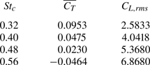
4. Conclusions
Transition of spanwise instability on primary leading edge vortex (LEV) rollers towards the formation of hairpin-like structures is observed in the wake of an oscillating foil with increasing  $St_c$ in the range $0.32 \le St_c \le 0.56$. This system of secondary hairpin-like vortical structures grows in conjunction with the previously identified hairpin-like pairs that evolve from the core vorticity outflux of deforming secondary LEVs (Verma & Hemmati Reference Verma and Hemmati2023; Verma et al. Reference Verma, Khalid and Hemmati2023). At $St_c = 0.32$, vortex undulations and spanwise dislocations do not reveal temporal amplification, and hence fail transition to another system of hairpin-like vortical structures. However, beyond $St_c = 0.32$, undulations amplify with advection of the LEV in the wake, which subsequently coincides with vortex tearing at localized spanwise locations along the roller. Hence the LEV itself transforms to the hairpin-like system that evolves in conjunction with the pre-existing hairpin-like structures. The amplification of undulations at $St_c > 0.32$ is associated with enhanced vortex compression and tilting around the upstream regions neighbouring primary LEVs. This also coincides with the presence and growth of counter-rotating trailing edge vortices (TEVs) that only act as a source for intensifying axial strain fields, while having no contribution in the onset of spanwise instability on the primary LEV. The increasing circulation of TEVs at higher $St_c$ further accelerates the intensification of compression, which coincides with an early growth of secondary hairpin-like system from the primary LEV.
Funding
This research has received support from the Canada First Research Excellence Grant. The computational analysis was completed using Compute Canada clusters.
Declaration of interests
The authors report no conflict of interest.
Author contributions
Authors may include details of the contributions made by each author to the paper.


 Open access