





1. Introduction
Simple magnetic mirror devices are intrinsically susceptible to magnetohydrodynamic (MHD) instabilities, among which interchange instability poses the most critical threat to plasma confinement. One of the most effective approaches for stabilising interchange modes is the use of rotational sheared flow. Although plasma rotation may drive certain MHD instabilities, the associated shear can reduce the intensity of the fluctuations, thereby suppressing radial transport and improving plasma confinement. This stabilisation approach has been extensively implemented in linear plasma devices. For example, the ‘Gas-dynamic Trap (GDT)’ team demonstrated stabilisation of the interchange mode via sheared flow, employing a method known as ‘vortex confinement’ (Beklemishev et al. Reference Beklemishev, Bagryansky, Chaschin and Soldatkina2010; Ryutov et al. Reference Ryutov, Berk, Cohen, Molvik and Simonen2011). Recent GAMMA 10 experiments have demonstrated the suppression of flute-like fluctuations via controlled potential formation (Yoshikawa et al. Reference Yoshikawa2019).
Control of the rotational shear can be achieved by applying different potentials to the internal electrode, which alters the rotation profile via E-cross-B drifts. Electrode biasing has been implemented in numerous fusion devices and many studies report successful regulation of rotational shear leading to enhanced plasma performance. Several linear plasma devices employ ring-shaped electrodes or use end-plates for potential control. In the recently developed mirror device, Wisconsin high-temperature superconductor axisymmetric mirror (WHAM), end-rings were installed to realise vortex confinement (Endrizzi et al. Reference Endrizzi2023). In early GAMMA 10 experiments, end-plate biasing was used to improve confinement time (Mase et al. Reference Mase, Itakura, Inutake, Ishii, Jeong, Hattori and Miyoshi1991).
The magnetic mirror configuration reproduces the magnetic-field structure of the scrape-off layer plasma in toroidal confinement systems, particularly with respect to edge plasma characteristics. Therefore, divertor simulation studies have progressed via the use of linear mirror devices. The GAMMA 10/PDX operated at the Plasma Research Center at the University of Tsukuba, have been investigated using the magnetic field in the end region (Nakashima et al. Reference Nakashima2017; Sakamoto et al. Reference Sakamoto2017). To advance divertor simulation research, a new plasma simulator, the Pilot GAMMA PDX-SC (PGX-SC) (Sakamoto et al. Reference Sakamoto2023), has been developed. The simulator employs a pair of superconducting coils to create a simple magnetic mirror configuration. PGX-SC was constructed in parallel with experiments conducted on GAMMA 10/PDX. The primary objective of the PGX-SC is to demonstrate the feasibility of using a simple magnetic mirror configuration as a divertor simulator and to enable systematic divertor simulation studies. GAMMA 10/PDX is a tandem mirror system with a minimum B-anchor to make plasma MHD stable. However, PGX-SC is a simple magnetic mirror device and an alternative method is required for plasma stabilisation.
An electrode-biasing system was installed at the east end of the main chamber of PGX-SC to suppress MHD instabilities using the method of vortex confinement. It consists of three concentric electrodes and its biasing voltage is supplied by an adjustable power source. Preliminary experiments on the electrode bias system were carried out in the PGX-SC. This paper reports on the details and results of those experiments. In this paper, § 2 describes the PGX-SC device and bias system. In § 3, we discuss the control of the plasma potential by the bias electrode in the PGX-SC. In § 4, we present our preliminary experimental results. Section 5 provides the concluding remarks.
2. Experimental set-up
The experiments were performed using the PGX-SC device consisting of a main chamber, divertor simulation chamber and plasma source. Figure 1(a) shows a schematic of the main chamber of PGX-SC. The inner diameter of the main chamber is approximately 1.15 m. The length of the new device is approximately 10 m and the plasma diameter in the divertor simulation region connected to the west end of the main chamber ranges from 0.1 to 0.2 m. A pair of superconducting (SC) coils with a bore diameter of 0.9 m in conjunction with a pair of copper coils (∼1.5 m diameter) were used to create a simple mirror configuration. The operating current of the SC coils is 236.3 A. A typical profile of the magnetic field along the z-axis is shown in figure 1(b). The magnetic field was calculated using the Biot–Savart law. The maximum magnetic field was 1.5 T and the mirror ratio was approximately 30. The target plasma parameters were as follows: plasma density of the order of 1019 m–3; electron and ion temperatures of several tens of electron volts; and discharge durations ranging from 10 to 100 s (Sakamoto et al. Reference Sakamoto2023).
Schematic view of the (a) main chamber and (b) axial magnetic field profile along the z-axis of the PGX-SC.

A differential pumping system and plasma source were installed to connect to the east end of the main chamber for plasma production. The main and differential pumping chambers were evacuated employing turbomolecular pumps with pumping speeds of 5400 L s–1 and 2700 L s–1 for hydrogen gas, respectively. Baffle plates and bushings were installed within the connection tube between the differential and main chambers. The neutral gas used for the plasma source was primarily pumped through a differential pumping chamber positioned between the plasma source and main chamber.
In PGX-SC, the plasma is directed from the plasma source into the main chamber, where heating is applied. A cascade arc plasma source was used for the long-pulse discharge, whereas a helicon wave plasma source was used for generating large-diameter plasma in other experiments. An ion cyclotron range of frequency (ICRF) antenna system was installed at z = 1.1 m from the midplane to the west end of the main chamber to perform beach heating with slow waves. Radio-frequency waves at 1.8 MHz, generated by a double half-turn antenna, were injected into the main chamber to heat the plasma. A Faraday shield was installed around the double half-turn antenna, and the plasma-facing surfaces of both the Faraday shield and antenna were tapered along the magnetic field lines. For electron cyclotron heating (ECH), 28 GHz microwave power generated by a gyrotron is transmitted through corrugated waveguides, mitre bends and a vacuum window into the main chamber. The microwave beam was ejected from the open-ended waveguide and reflected by the mirror antenna to reach the 0.5 T surface of the second harmonic of the electron resonance. The plasma-edge bias system comprised three concentric electrodes. Figure 2 shows a schematic view and photograph of the electrodes. The inner radii of the inner, middle and outer plates were 70, 100 and 130 mm, respectively. The width of each ring-shaped electrode was 15 mm. The three electrodes are designated as ‘inner (I)’, ‘middle (M)’ and ‘outer (O)’ electrodes. The bias electrodes (I, M and O) were operated using switches to perform the following three operations. Each plate was configured to operate in either floating, grounded or biased modes. Within PGX-SC, the electrode biasing system also defines part of the axial boundary conditions of the main chamber. Floating potential measurements were performed by connecting a 10-MΩ resistor in series to electrically isolate the electrode. The signals were isolated from the local ground using an isolation amplifier and subsequently recorded by a digitiser. Grounded operation permits measurement of the current flowing from the plasma into the electrode; the collected current is measured using a voltage monitor. Furthermore, direct current (DC) bias voltages can be applied by connecting a DC-stabilised power supply to the electrode. The bias power supply provides an adjustable output within the range 0–250 V with a maximum power of 15 kW. When the bias voltage was less than 250 V, arcing near the electrodes was not observed even in the presence of the plasma. The power supply enabled electrode biasing with respect to ground. A set of programmable power supplies was used to power each electrode. During plasma discharges, the current drawn by each electrode increased; however, the electrode voltages remained at their preset values. These results confirm that the bias voltages were stably controlled using a bias power supply throughout the preliminary experiments.
(a) Schematic view and (b) the photograph of the three concentric electrodes of the bias system.

3. Interaction of the electrode biasing system and plasma
Plasma potential plays a central role in maintaining quasi-neutrality (Beklemishev et al. Reference Beklemishev, Bagryansky, Chaschin and Soldatkina2010). Under steady-state conditions, the plasma potential is determined by the balance between electron and ion losses. This condition requires the divergence of the current within the plasma to vanish; therefore,
 \begin{equation} \boldsymbol{\nabla }\boldsymbol{\cdot }(\boldsymbol I_{//}\rm+ \boldsymbol I_{\bot }\rm)=0, \end{equation}
where $\boldsymbol I_{//}$
denotes the current along the magnetic field line and
$\boldsymbol I_{//}$
denotes the current along the magnetic field line and $\boldsymbol I_{\bot }$
is radial current across magnetic field lines. The axial current was determined using the electrode and plasma sheath.
$\boldsymbol I_{\bot }$
is radial current across magnetic field lines. The axial current was determined using the electrode and plasma sheath.
The resulting sheath structure depends on the electrode bias relative to the plasma potential. An electrode bias voltage below the plasma potential results in an ion sheath. If the sheath in front of the electrode is an ion sheath, ions are collected by the electrode with a current of I i (Baalrud et al. Reference Baalrud, Scheiner, Yee, Hopkins and Barnat2020), given by
 \begin{equation} I_{i}=e{\varGamma} _{i}A_{E}\quad \mathrm{and}\quad {\varGamma} _{i}=\exp (-1/2)C_{S}n_{e}, \end{equation}
where AE denotes the plasma-collecting area, Cs is the speed of sound and ne represents the electron density. Electrons are also simultaneously collected by the electrode with a current Ie (Baalrud et al. Reference Baalrud, Scheiner, Yee, Hopkins and Barnat2020), expressed as
 \begin{equation} I_{e}=e{\varGamma} _{e}\!\exp (-e(\varphi _{p}-\varphi _{E})/T_{e})A_{E}\quad \mathrm{and}\quad {\varGamma} _{e}=V_{e}n_{e}/4. \end{equation}
Here, $\varphi _{p}$
denotes the plasma potential,
$\varphi _{p}$
denotes the plasma potential, $\varphi _{E}$
represents the bias voltage of the electrode and Ve
is the mean electron velocity. If the electrode bias exceeds the plasma potential, an electron sheath is formed in front of it. In this case, ions do not flow into the electrode and are only lost to the opposite chamber wall (Baalrud et al. Reference Baalrud, Scheiner, Yee, Hopkins and Barnat2020). Electron current expressions that incorporate the effects of electron presheath and loss cone distribution have been reported (Baalrud et al. Reference Baalrud, Scheiner, Yee, Hopkins and Barnat2020). These axial currents are proportional to collecting area AE
; therefore,
$\varphi _{E}$
represents the bias voltage of the electrode and Ve
is the mean electron velocity. If the electrode bias exceeds the plasma potential, an electron sheath is formed in front of it. In this case, ions do not flow into the electrode and are only lost to the opposite chamber wall (Baalrud et al. Reference Baalrud, Scheiner, Yee, Hopkins and Barnat2020). Electron current expressions that incorporate the effects of electron presheath and loss cone distribution have been reported (Baalrud et al. Reference Baalrud, Scheiner, Yee, Hopkins and Barnat2020). These axial currents are proportional to collecting area AE
; therefore,
 \begin{equation} I_{e}=\alpha e{\varGamma} _{e}A_{E}, \end{equation}
where $\alpha$
is the factor determined by these effects, with a value typically ranging from 1 and 1.5.
$\alpha$
is the factor determined by these effects, with a value typically ranging from 1 and 1.5.
The radial current depends on plasma properties. In partially ionised plasmas, cross-field transport is primarily governed by ion-neutral collisions (Curreli & Chen Reference Curreli and Chen2014). In the current PGX-SC experiment, the relatively high density of neutral particles significantly contributes to the radial current via ion diffusion processes. This diffusion mechanism generates a radial E-field which drives the ions radially. As the intensity of the plasma fluctuation increases, the polarised drift also contributes to the radial current.
The overall balance between the electron and ion losses determines the plasma potential. The spatial distribution of the plasma potential was regulated by adjusting the electrode bias voltage, which modified the axial current. As the electrode bias voltage increased, the plasma potential also increased to satisfy the quasi-neutrality conditions described previously. Effects associated with the electric contact of the plasma with the end-plate have been previously summarised in detail (Ryutov et al. Reference Ryutov, Berk, Cohen, Molvik and Simonen2011). Specifically, the GDT team has reported that sufficient strong positive biasing of the outer plasma surface leads to improved plasma stability (Beklemishev et al. Reference Beklemishev, Bagryansky, Chaschin and Soldatkina2010). ‘Vortex stabilisation’ is achieved through shear flows occurring near the plasma boundary, which prevent the central plasma from crossing the boundary. These shear flows can be generated by creating a radial distribution of the concave potential using the plasma-edge bias system. Preliminary experimental results suggested that the bias voltage applied to the electrodes caused changes in the plasma potential. These findings are described in the following section.
4. Preliminary experiments
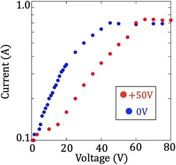
This section presents the results of the preliminary experiments conducted using the electrode bias system in PGX-SC. Figure 3 shows the collected current of electrode O as a function of its applied voltage of the electrode O, exhibiting a characteristic sheath current–voltage response.
Collected current as a function of applied voltage to electrode O. The blue circles show the data when electrode I is grounded, whereas the red circles correspond to the bias +50 V applied to electrode I.

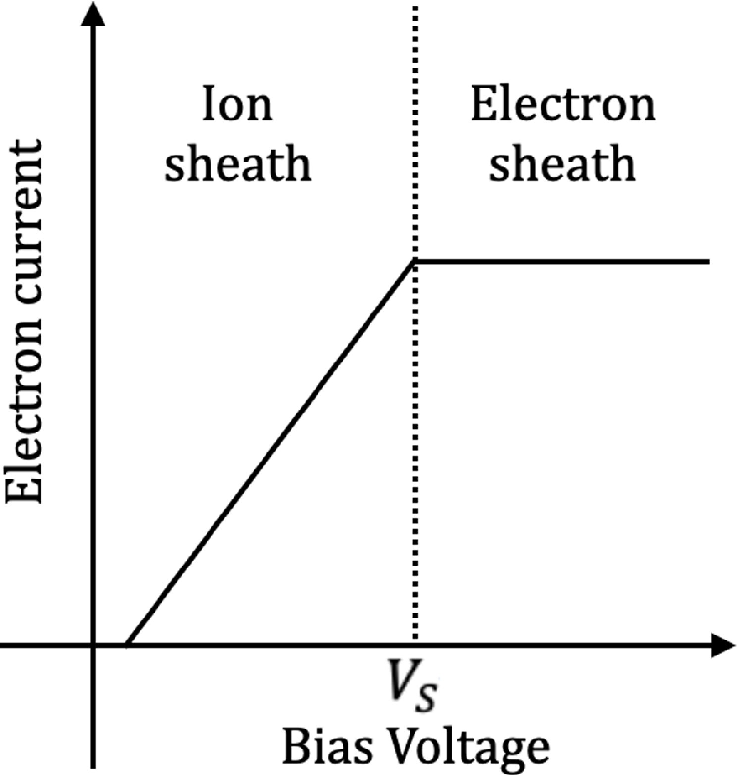
Schematic of the electron current collected by the electrode (predicted from (3.3) and (3.4) with $\alpha$
= 1) as a function of the bias voltage of the electrode. In this figure, the electron temperature is constant and the vertical axis is on a logarithmic scale. The minimum bias voltage at which the electron sheath is formed is reached is denoted by
$\alpha$
= 1) as a function of the bias voltage of the electrode. In this figure, the electron temperature is constant and the vertical axis is on a logarithmic scale. The minimum bias voltage at which the electron sheath is formed is reached is denoted by $V_{S}$
.
$V_{S}$
.

In this experiment, a steady-state DC discharge was used as the plasma source and electrode M was grounded. The blue circles indicate the data when electrode I was grounded, whereas the red circles indicate the data when a voltage of +50 V was applied to electrode I. The measured currents were considerably lower than the power supply rating. In both cases, the power supply current became saturated as the applied voltage increased. This phenomenon indicates that the ion sheath transitioned into an electron sheath, as noted in the previous section. Before saturation, the electron current I
e
follows (3.3) and depends on the applied voltage $\varphi _{E}$
. After saturation, the electron current I
e
follows (3.4) and is independent of the applied voltage
$\varphi _{E}$
. After saturation, the electron current I
e
follows (3.4) and is independent of the applied voltage $\varphi _{E}$
. This is illustrated in figure 4. A schematic of the electron current I
e
calculated using (3.3) and (3.4) with
$\varphi _{E}$
. This is illustrated in figure 4. A schematic of the electron current I
e
calculated using (3.3) and (3.4) with $\alpha$
= 1 as a function of the electrode bias voltage is shown in figure 4. When an electron sheath forms in front of the electrode, only the electron current, which is independent of the applied voltage
$\alpha$
= 1 as a function of the electrode bias voltage is shown in figure 4. When an electron sheath forms in front of the electrode, only the electron current, which is independent of the applied voltage $\varphi _{E}$
, is collected by the electrode. Consequently, the applied voltage at which the ion sheath transitions to the electron sheath and the power supply current reaches saturation corresponds to the plasma potential. In this case, according to (3.3),
$\varphi _{E}$
, is collected by the electrode. Consequently, the applied voltage at which the ion sheath transitions to the electron sheath and the power supply current reaches saturation corresponds to the plasma potential. In this case, according to (3.3), $\varphi _{E}$
is equal to
$\varphi _{E}$
is equal to $\varphi _{P}$
. The minimum applied voltage at which this saturation is reached is denoted by
$\varphi _{P}$
. The minimum applied voltage at which this saturation is reached is denoted by $V_{S}$
in figure 4. In figure 3,
$V_{S}$
in figure 4. In figure 3, $V_{S}$
was approximately +20 V higher when +50 V were applied to electrode I than that attained when the electrode was grounded. Therefore, these results indicate that applying a voltage to electrode I increased the plasma potential at electrode O. When an electron sheath forms in front of the electrode, increasing the applied voltage
$V_{S}$
was approximately +20 V higher when +50 V were applied to electrode I than that attained when the electrode was grounded. Therefore, these results indicate that applying a voltage to electrode I increased the plasma potential at electrode O. When an electron sheath forms in front of the electrode, increasing the applied voltage $\varphi _{E}$
does not increase the electron current, and (3.1) becomes independent of the applied voltage
$\varphi _{E}$
does not increase the electron current, and (3.1) becomes independent of the applied voltage $\varphi _{E}$
. In the saturation phase, the plasma potential depends not on
$\varphi _{E}$
. In the saturation phase, the plasma potential depends not on $\varphi _{E}$
, but other parameters. One of them is the neutral density. An increase of the neutral particle density leads to a decrease in potential. Even if the applied voltage
$\varphi _{E}$
, but other parameters. One of them is the neutral density. An increase of the neutral particle density leads to a decrease in potential. Even if the applied voltage $\varphi _{E}$
is increased, the potential
$\varphi _{E}$
is increased, the potential $\varphi _{P}$
does not rise. The importance of reducing the neutral gas density has already been reported (Ryutov et al. Reference Ryutov, Berk, Cohen, Molvik and Simonen2011).
$\varphi _{P}$
does not rise. The importance of reducing the neutral gas density has already been reported (Ryutov et al. Reference Ryutov, Berk, Cohen, Molvik and Simonen2011).
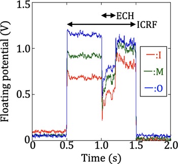
Next, we discuss the experimental results of plasmas heated by ECH and ICRF. Figure 5 shows the temporal evolution of the floating potential measured using electrodes I, M and O. The red, green and blue lines represent data from electrodes I, M and O, respectively. During this experiment, the helicon discharge plasma source was operated at a set power of 1 kW. The ICRF was injected at an output of 134 kW and ECH of 326 kW. A positive floating potential at all the electrodes during plasma discharge indicates that the plasma potential is positive. As the floating potential contains information on the plasma potential, measuring either the electron temperature or plasma potential using other detectors enables the other parameter to be estimated. However, these detectors were not installed in the main chamber. The plasma remained stable, suggesting that a radial potential distribution capable of suppressing MHD instabilities may have been established. Once electron temperature distributions are obtained from the detectors to be installed, the plasma potential distribution can be estimated, which is crucial for plasma stabilisation (Beklemishev et al. Reference Beklemishev, Bagryansky, Chaschin and Soldatkina2010; Ryutov et al. Reference Ryutov, Berk, Cohen, Molvik and Simonen2011).
Temporal evolution of the floating potential measured at electrodes I, M and O. The red, green and blue lines represent data from electrodes I, M and O, respectively.

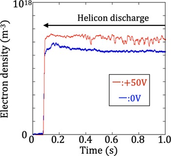
Temporal evolution of the electron density measured by the microwave interferometer within the main chamber. The blue line shows the line density when all electrodes are grounded, whereas the red line corresponds to the bias of +50 V applied to electrode I and the other grounded electrode.

To investigate the effect of electrode voltage on plasma density, plasma density was measured with and without a voltage applied. Figure 6 shows the temporal evolution of the electron density measured using the microwave interferometer within the main chamber. Electron density data were estimated using the measured line density and plasma diameter. The blue line shows the line density when all electrodes were grounded, whereas the red line corresponds to a bias of +50 V applied to electrode I and the other grounded electrodes. During this experiment, a helicon discharge commenced at 0.08 s, while the heating system remained inactive throughout this period. Notably, the electron density and its fluctuations increased when a voltage was applied to the inner electrode. These results suggest that the electrode voltage influenced the plasma electron density. The increase in the plasma potential owing to the electrode voltage might have improved the axial confinement of electrons, but may have induced plasma instabilities. The positive plasma potential generated by the voltage applied to the electrodes may act as an axial electron confinement potential (Pastukhov Reference Pastukhov1974; Cohen et al. Reference Cohen, Rensink, Cutler and Mirin1978). Shear flow has been reported to drive Kelvin–Helmholtz instabilities (Ryutov et al. Reference Ryutov, Berk, Cohen, Molvik and Simonen2011). Measuring the shape of the radial potential distribution is crucial to elucidating this phenomenon. However, as no other experimental data were obtained at this stage, a detailed investigation of the cause will be addressed in a future study.
To investigate the influence of electrode voltage on plasma fluctuations, spectral analysis was performed on the current flowing into the electrodes while voltage was applied. Figure 7 shows the power spectra of the inflow current of the grounded electrode M when a voltage is applied to electrode I. In this experiment, a steady-state direct-current discharge was used as the plasma source and the heating system was not in operation. The cutoff frequency of the low-pass filter used in the circuit was 1.7 MHz. The blue circles represent the power spectrum with grounded electrode O, whereas the red circles indicate the spectrum with a +50 V bias applied to electrode O.
Fluctuations were observed within the frequency range 600–800 kHz. When +50 V was applied to the outer electrode O, a reduction in fluctuation intensity was observed. These fluctuations are likely the result of MHD instability or some of the instabilities excited by the electrodes (Iizuka, Takeda & Sato Reference Iizuka, Takeda and Sato2001); however, definitive identification requires additional diagnostics. These results indicate that the application of the electrode voltage influenced the plasma instability.
Power spectra of the inflow current of the grounded electrode M when voltage is applied to electrode I. The blue circles represent the power spectrum with grounded electrode O, whereas the red circles indicate the spectrum with a +50 V bias applied to electrode O.

5. Summary
Electrode-biasing experiments were performed using a recently constructed PGX-SC magnetic mirror device. Cascade arc plasma and helicon plasma serve as seed plasmas. The PGX-SC is a device that directs plasma from a plasma source into the main chamber for heating and mirror confinement. The plasma-heating equipment uses ICRF and ECH. Plasma in a magnetic mirror configuration is intrinsically susceptible to MHD instabilities. Therefore, the electrode system for stabilisation was installed at the edge of the main chamber. This technique is widely known as the vortex confinement method, which was developed for the Russian device, the GDT. This method is based on the theory that the plasma potential is determined by quasi-neutral conditions and is controlled by adjusting the axial current using the electrode bias voltage. The electrode system consists of three concentric ring-shaped electrodes and a DC stabilised power supply for each base plate. This system can also measure the floating potentials and currents flowing into the electrodes from the plasma by connecting a resistor to the plate without using a power supply. Preliminary experiments were conducted in this relatively high-neutral-density plasma, which contributed to the radial current by ion-neutral collisions. In some experiments, results regarding the current–voltage curve of the outer electrode were obtained and the plasma potential was estimated from the ‘knee’ of that curve. This potential increased when a voltage was applied to the inner electrode. These experimental results demonstrate that the spatial plasma potential follows changes in the bias voltage. Other preliminary experiments revealed that the applied electrode voltage influenced the plasma potential and density. This bias likely results in the suppression of instability in the plasma. Because the PGX-SC has a simple magnetic mirror configuration, the results may shed light on the bias experiments of many magnetic mirrors and mirror-like devices. Further experimental and diagnostic investigations will be undertaken to clarify underlying mechanisms and quantify stabilisation performance.
Acknowledgements
Editor Cary Forest thanks the referees for their advice in evaluating this article.
Declaration of interest
The authors report no conflict of interest.






 Open access

