

1. Introduction and History of Disc and Replicate Coring System
The development of the deep ice sheet coring (DISC) drill has a long history (Reference JohnsonJohnson and others, 2007; Reference Mason, Shturmakov, Johnson and HamanMason and others, 2007; Reference Mortensen, Sendelbach and ShturmakovMortensen and others, 2007; Reference Shturmakov and SendelbachShturmakov and Sendelbach, 2007; Reference Shturmakov, Lebar, Mason and BentleyShturmakov and others, 2007; Bentley and others, 2008). After the DISC drill test in Greenland in 2006, the system was shipped to the West Antarctic Ice Sheet (WAIS) Divide (Fig. 1), where it was used for five consecutive production field seasons from 2007 to 2013. A total of 3405m of ice core was drilled, setting the US deep ice-drilling record. In 2008, the US National Science Foundation (NSF) tasked Ice Coring and Drilling Services (ICDS), and later Ice Drilling Design and Operations (IDDO), to begin the detailed design process for the new replicate coring system (RCS), and by September 2011 the design and construction of the new system was completed. The first test of the RCS at WAIS Divide was conducted during the 2011/12 WAIS Divide field season, and the first replicate core production season during the 2012/13 season at WAIS Divide resulted in the coring of 285 m of ice core taken from five controlled deviations at four depth levels.

Fig. 1. Aerial view of the WAIS Divide camp. Photo credit: Lockheed Martin (ASC).
The following sections provide an overview of the DISC drill and RCS with additional technical details described in companion papers (Reference JohnsonJohnson and others, 2007; Reference Mason, Shturmakov, Johnson and HamanMason and others, 2007; Reference Mortensen, Sendelbach and ShturmakovMortensen and others, 2007, Reference Mortensen, Johnson and Shturmakov2014a,Reference Mortensen, Goetz, Gibson, Johnson and Shturmakovb; Reference Shturmakov and SendelbachShturmakov and Sendelbach, 2007; Reference Shturmakov, Lebar, Mason and BentleyShturmakov and others, 2007; Bentley and others, 2008; Reference Gibson, Johnson, Shturmakov, Mortensen and GoetzGibson and others, 2014; Reference Johnson, Mortensen, Gibson, Goetz and ShturmakovJohnson and others, 2014) with the summary of the production drilling process in Reference SlawnySlawny and others (2014). In addition, the science requirements and concepts that led to the technical development strategy for replicate coring are defined.
2. Latest Configuration of the Base Disc Cable-Tethered Electromechanical Drill System
The DISC drill (Fig. 2; Reference Shturmakov, Lebar, Mason and BentleyShturmakov and others, 2007) was incrementally improved after each season, with changes including, but not limited to: mechanical changes to improve the accuracy of the weight-on-bit sensor; structural analysis, and strengthening of the crown sheave; redesign of the level wind for the 4000 m winch, for improved reliability and accuracy (Reference Mortensen, Goetz, Gibson, Johnson and ShturmakovMortensen and others, 2014b); modifications to the temperature sensor housing to improve accuracy; revision of the LabVIEW code to improve the user interface.

Fig. 2. DISC drill system layout at WAIS Divide.
The final configuration of the drill used for coring the parent borehole consisted of:
Two-motor (tripping 2.2 kW motor and 112 kW penetration drive motor) winch system with automatic level wind (Reference Mortensen, Johnson and ShturmakovMortensen and others, 2014), speeds up to 2.5 ms−1, 4000 m cable capacity and feed resolution of 0.1 mms−1
15.2 mm diameter fiber-optic cable with six 62.5 μm multimode fibers; the cable has a multilayer construction (Reference Shturmakov and SendelbachShturmakov and Sendelbach, 2007) with optical fibers wrapped around the king wire and isolated by a buffer, with eight copper-clad steel wires wrapped around this core; it also includes two layers of high-density polyethylene (HDPE) belt material, 60 smaller copper wires, two layers of strength steel wires, and a proprietary void filler to prevent drill fluid from attacking the inner belt
Tilting tower, ∼15.0m long
Sonde:
-
Configurable length up to 15 m with up to 4 m core barrel
-
Separate motors for cutter (1.8 kW, 7500 rpm) and pump (2.5 kW, 3500rpm)
-
Pump that powers a reverse-circulation chip collection circuit that circulates drilling fluid to transport ice chips upward from the cutter to the screens where they are collected; pump is capable of 1200–3000 rpm, with the best performance between 2100 and 2300 rpm and flow rate of 284–322Lmin−1 and pressures of 41.4–55.2 kPa
-
Anti-torque, instrument section, motor/pump section, screen barrel, core barrel, cutter head
LabVIEW software-based sonde and winch control system
Instrument section: 1 kV to 300 V, 5 kW d.c.–d.c. converter (fig. 6 in Reference Mortensen, Sendelbach and ShturmakovMortensen and others, 2007); eight servomotor drives; multi-sensor system; five processors/controllers
Support systems: screen-cleaning table, barrel-turning fixture, centrifuge, chip hopper, pilot hole/casing, MECC Machine and Electronics Shop, other
Drilling fluid (two-part system): Isopar K with 0.76gcm–3 specific gravity and HCFC-141b with 1.24 g cm–3 specific gravity, mixed at a 70/30 ratio by volume; the final mixture has a 0.935 g cm–3 specific gravity at –31°C; fluid samples from borehole consistently measured 0.920gcm–3 at –31°C
Thin kerf cutter head and core barrel which produces a 163 mm diameter borehole, rather than the original diameter of 170mm
Ice-core diameter remains at 122 mm, with core lengths up to 4.0m and average core length of 3.2 m.
3. Replicate Coring System Design
Design of the RCS began with the development of science and engineering requirements for the system. The US ice-coring science community developed the science requirements which included core quality, the desired length of core, the number of deviations for core at specific depths, etc. IDDO developed engineering requirements which included various drill parameters necessary to meet the science requirements.
The RCS requirements were widely discussed during a number of meetings between US and international ice scientists and IDDO engineers. The main requirements are as follows:
-
(a) The parent borehole must remain open and usable after replicate coring has occurred; no reduction in diameter of the parent borehole is allowed.
-
(b) Replicate coring should be possible at any location of the borehole, starting 100 m below casing end.
-
(c) Damage to the parent borehole should be minimized.
-
(d) Deviations would be made on the ‘uphill’ side of the borehole to facilitate logging of the borehole.
-
(e) Borehole inclinations must be measured with an accuracy of ±5°.
-
(f) The system must be operational at temperatures down to –55°C.
-
(g) Any equipment that is to remain in the parent borehole permanently must have an inner dimension equal to or larger than that of the parent borehole so the parent borehole is not obstructed.
-
(h) Up to four replicate cores should be obtainable at a depth of particular interest; if more than one deviation at a given depth is to be performed, they do not have to be on the ‘uphill’ side of the parent borehole.
-
(j) A replicate core must be at least 1 m in length, although 2 m is desirable.
-
(k) The replicate core should be at least 106 mm in diameter.
-
(l) The replicate core collected must be collected within 20 m of the parent borehole.
-
(m) The replicate core should be of the same high quality as that taken from the parent borehole.
-
(n) The RCS could be applied to other, already developed, drills.
4. Replicate Coring System Concepts
IDDO considered two approaches to the recovery of replicate core: use of a whipstock or a tapered device anchored in the borehole (passive replicate coring drill) (Fig. 3a and b) and use of an active steerable replicate coring drill (Fig. 4). Each method has its own advantages and disadvantages.

Fig. 3. (a) Passive replicate coring drill, type 1 . (b) Passive replicate coring drill, type 2.

Fig. 4. (a) Active steerable replicate coring drill, schematic. (b) Active steerable replicate coring drill, SolidWorks view.
4.1. Passive replicate coring drill
Two variations of the passive drill system were considered: a whipstock positioned on sacrificial aluminum support tubes (type 1 ; Fig. 3a), which is the less expensive solution using a whipstock; and a whipstock positioned above a remotely actuated clamping mechanism (type 2; Fig. 3b), which requires the design and fabrication of the mechanism and would be, consequently, more expensive.
-
The advantages are:
-
The passive drill concept is less complicated and therefore less expensive
-
The replicate borehole could be available for logging
The disadvantages are :
-
Type 1 would not meet requirements (a), (c), (d), (g) and (h)
-
Type 2 would not meet requirements (h) and (n)
-
Risk of intersecting the original borehole
-
Risk of losing the drill stuck during the deviation
-
With the type 1 whipstock, the last 400–450 m of the main hole are ‘plugged’, precluding any possibility of logging without reaming, because the whipstock and the sacrificial support tubes cannot be easily removed from the parent borehole
-
Potential environmental impact of materials used to set a whipstock due to difficulty of removing these materials if they are stuck in the parent borehole
-
The type 1 whipstock system is not reusable
The actuator-based system is chosen in preference to the originally intended whipstock system (type 1 or 2). This choice was made based on two major characteristics.
-
1. The RCS should be capable of performing multiple deviations at the same depth, leading to serious concerns that boreholes may accidentally intersect. This could be avoided by steering the drill using the actuators.
-
2. There is a desire to apply the system to other deep drills. Other drills are less suited for a whipstock-based approach than the DISC drill (non-rotating barrel, low fluid flow and low power budget).
A consequence of these two aspects, and the resulting solution to overcome the penalties they represent, is an active replicate coring drill system presented below.
4.2. Active replicate coring drill (IDDO design; Fig. 4)
The advantages are :
-
Meets all of the science requirements
-
The system concept is modular in nature and can therefore be integrated into the base DISC drill or other drill systems
-
The electromechanical design of the active steerable replicate system will allow for monitoring of the existing three-dimensional orientation of the DISC drill to avoid intersection with the main borehole
-
Eliminates the potential of getting a whipstock stuck in the main borehole
The disadvantages are:
-
More expensive than the whipstock approach
-
Entering the deviation borehole after it has been established is precise and will require active navigation during operation
-
The actuator sections add length to the drill, but screen and core barrels will be shortened, resulting in a slightly longer drill.
Based on the analysis of these two major approaches and after consultations with the science community, IDDO decided to pursue the active steerable replicate coring drill. Two major advantages of the active system led to this decision, meeting all of the science requirements and the possibility of integrating the modular RCS into the DISC drill and other drill systems in the future.
5. Main Replicate Coring System and Subsystems
The RCS is a modular addition (Fig. 5) to the base DISC drill system that can be deployed into an existing parent borehole created with the DISC drill and can deviate from the parent borehole to retrieve cores up to 2.0 m long. Core and borehole diameters are as follows: main core diameter 122 mm; replicate core diameter 108 mm (Fig. 6); parent borehole diameter 164 mm; replicate borehole diameter 148 mm.
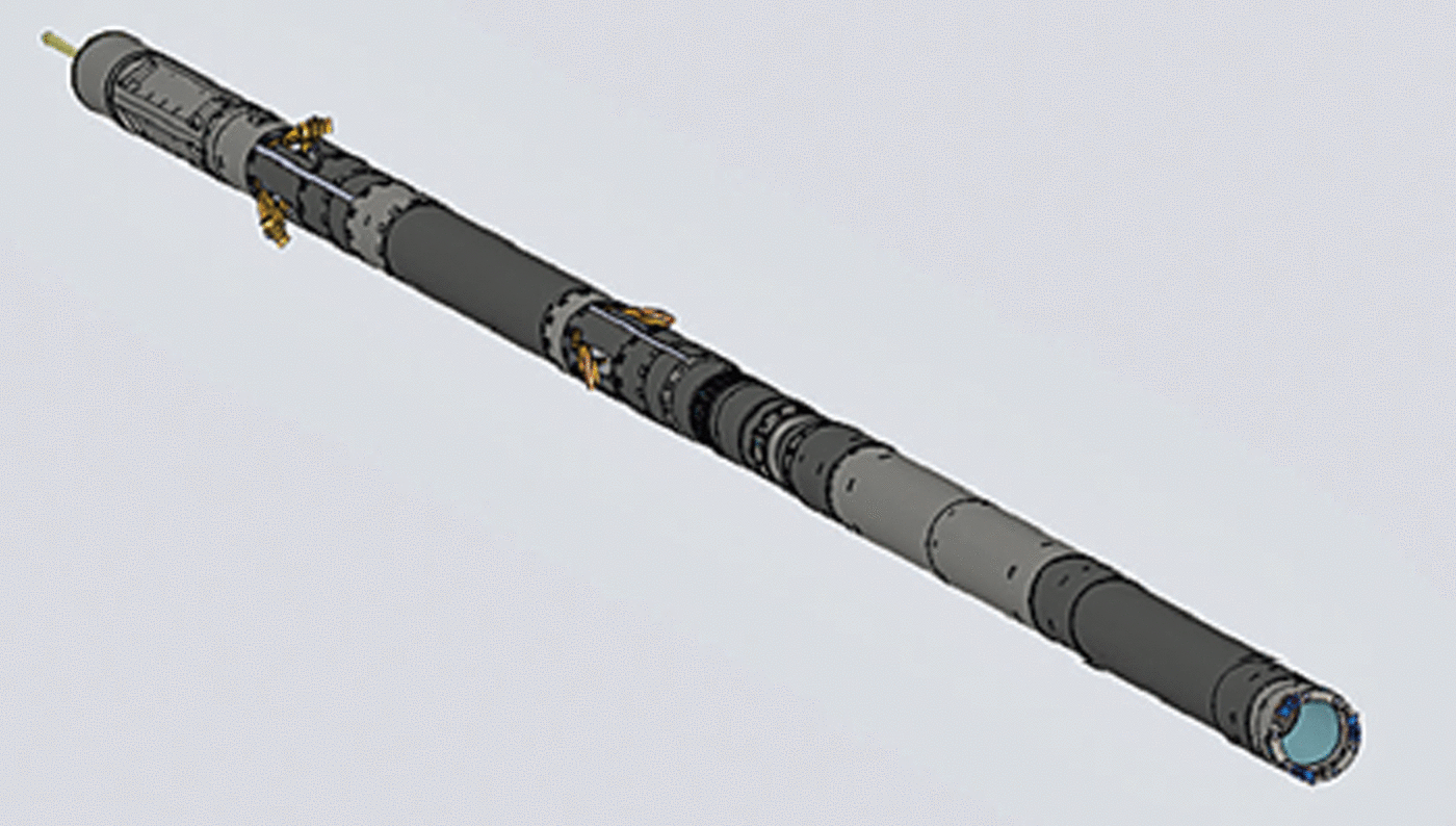
Fig. 5. Replicate coring sonde.

Fig. 6. First replicate ice core produced at WAIS Divide.
In order to add the new replicate coring capability to the existing DISC drill, the entire system required modification – mechanical, electrical, electronic and software – and the design and implementation of new subsystems. The new system upgrades included modification and building of new components for the motor/pump section, the cable interface section, chip collection section, core barrel section, fluid delivery module, cutter heads, borehole camera, and downhole and surface equipment to allow for the smaller diameter of the replicate drill. Five new circuit boards (Fig. 11, further below) and modified LabVIEW and C language software tied the base DISC drill and RCS together and provided replicate system navigation (Reference Mortensen, Johnson and ShturmakovMortensen and others, 2014a).
The major subsystems added to the base DISC drill were the actuator sections, a new control system, new deviation cutter heads and smaller-diameter core barrels, and a new borehole camera (Reference Gibson, Johnson, Shturmakov, Mortensen and GoetzGibson and others, 2014; Reference Mortensen, Johnson and ShturmakovMortensen and others, 2014a,Reference Mortensen, Goetz, Gibson, Johnson and Shturmakovb). These are described below.
5.1. Actuator sections
The actuator sections (Reference Gibson, Johnson, Shturmakov, Mortensen and GoetzGibson and others, 2014) added to the base DISC drill enable the drill to be tilted in the borehole and pushed against the borehole wall to make the desired deviation. The actuator subsystem consists of two three-lever/cam actuators to ensure that forces can be delivered in any radial direction (Figs 7 and 8). The three cams are located 120° apart. Power is applied using three brush-type electric d.c. motors. The motors and reducers are maintained in a hydraulic fluid with a pressure compensator similar to that used in the DISC drill’s existing motor section. The linkage assembly is exposed to drill fluid. Each lever can be individually extended to the 80° angle and is equipped with a mechanical fuse.
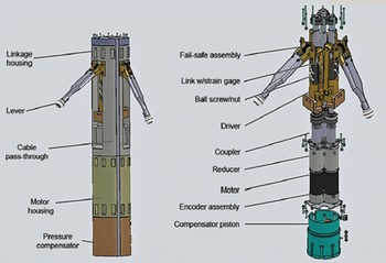
Fig. 7. Actuator module schematic.

Fig. 8. Actuator section with actuator arms extended.
The design is relatively simple and minimized the modifications needed to the base DISC drill.
5.2. Control system
The replicate coring control system serves two major functions: to be able to situate the drill in the required coordinate position and to be able to correct this position by steering itself and executing the operator’s command (Reference Mortensen, Johnson and ShturmakovMortensen and others, 2014a).
The replicate coring control system consists of a few major components and includes Glassman 1kV regulated d.c. power supply for the drill, and surface and onboard computers. The surface computers, used with the base DISC drill and LabVIEW software, provide the user interface.
The six levers (three per actuator section) are used to achieve the deviation capability of the drill. Each of the levers is motor-driven with a closed-loop motor controller for each motor. This requires controlling six independent axes. For deviation to occur in a desired direction, two of the three levers of each actuator module need to be moved correctly to direct the forces from the levers necessary for the deviation at the correct azimuth. The drill operator can input the azimuth as well as the amount of force applied by the levers.
The control system design makes the drill capable of easily providing the desired force against the borehole wall with minimum operator intervention. Figure 9 shows the system control room, and Figure 10 shows one of the control displays.

Fig. 9. Replicate coring control room.

Fig. 10. Replicate coring control display.
The downhole portion of the control system includes a 15.2 mm diameter fiber-optic communication cable (Reference Shturmakov and SendelbachShturmakov and Sendelbach, 2007), custom-made by Rochester Wire and Cable; eight servomotor drives; six actuator motors; a cutter motor and a pump motor; a sensor control system, along with temperature, pressure, navigation and magnetic (linear variable differential transformers (LVDTs) and resolver) sensors and five processors/controllers with analog-to-digital (A/D) and digital-to-analog interfaces. A LVDT interface allows operators to control each individual actuator (Reference Mortensen, Johnson and ShturmakovMortensen and others, 2014a).
The new replicate coring control module is presented in Figure 11. Figure 12 shows the drill inclinometer board; the actual inclinometer accuracy during the production drilling was ∼±0.01°. Figure 13 shows the 3DM-GX1 system navigation sensor made by MicroStrain. 3DM-GX1® combines three angular rate gyros with three orthogonal d.c. accelerometers, three orthogonal magnetometers, multiplexer, 16-bit A/D converter, and embedded microcontroller, to output its orientation in dynamic and static environments.
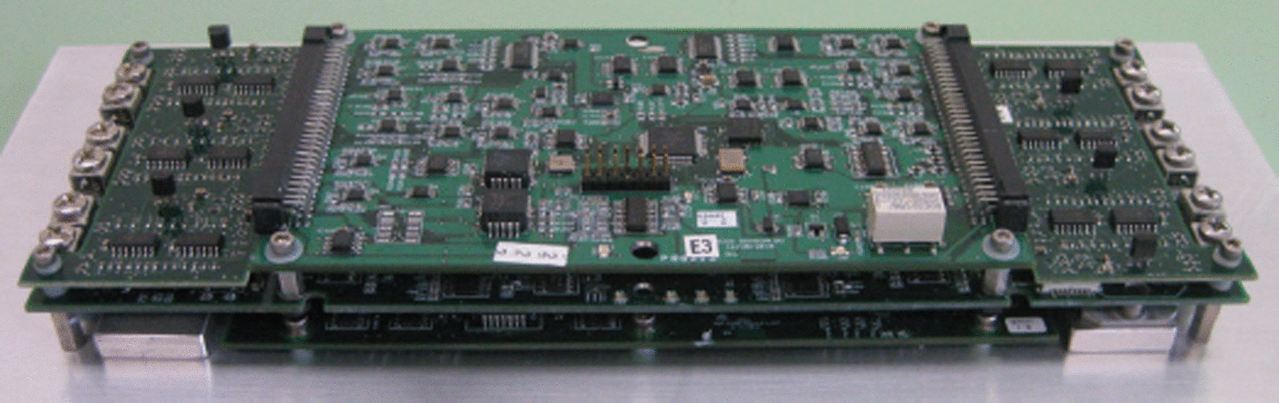
Fig. 11. Replicate coring control module.

Fig. 12. Inclinometer circuit board.

Fig. 13. Navigation sensor.
5.3. Smaller-diameter core barrels and new cutting heads
The replicate coring drill employs new smaller-diameter core barrels (137.0/151.5 mm inner diameter (ID)/outer diameter (OD) DISC drill vs 127.0/139.7 mm ID/OD RCS) along with smaller-diameter 3-cutter coring heads (Reference Gibson, Johnson, Shturmakov, Mortensen and GoetzGibson and others, 2014). The smaller-diameter core barrels and cutter heads are necessary to allow the deviation to be made. The modular ice chip screens for the replicate coring drill have the same 108.0 mm ID and 119.1 mm OD as the base DISC drill.
The set of heads used for the replicate coring drill consists of a coring head (Fig. 14), a milling cutter head with shoes (Fig. 15), a broaching head (Fig. 16), a conical retrieval head (Fig. 17) and a magnetic retrieval head (Fig. 18). The replicate coring drill assembly with a milling head is presented in Figure 19. Each of these accessories serves a very specific purpose. The procedure was developed to start the deviation from the parent borehole and to perform the replicate coring itself; this procedure and the use of the different cutter heads is described in detail by Reference Gibson, Johnson, Shturmakov, Mortensen and GoetzGibson and others (2014). The new milling head includes the radial and axial shoes and provides an improved geometry for axial cutting. The head prioritizes axial cutting over radial cutting and minimizes cutter contact with the borehole wall. The axial feed rate is up to 50 mms−1, and the minimum controlled axial feed is 1 mm per tooth. The cutters have a 30° rake angle, a 9° relief angle and minimized cutter height. A milling cutter head and a broaching cutter head are utilized to start a deviation, and then a newly designed coring cutter head is used to retrieve replicate cores. A conical tool and a magnet head are the emergency recovery tools needed to ‘clean’ the replicate borehole of metal and non-metal debris or broken cutter head parts.

Fig. 14. Coring head.

Fig. 15. Milling head.

Fig. 16. Broaching head.

Fig. 17. Conical head.

Fig. 18. Magnetic head.

Fig. 19. Replicate coring drill with a milling head.
5.4. Borehole camera
One of the new subsystems that were designed and built before the 2011/12 field season at WAIS Divide is the borehole camera (Fig. 20). This battery-powered camera has a LED light ring at the front and is designed to internally record video data during borehole trips (Fig. 21).

Fig. 20. Borehole camera mounted in the core barrel.

Fig. 21. Images of parent and replicate boreholes.
5.5. System characterization, validation and field testing
The replicate coring system was ready for the test at WAIS Divide in January 2012. Three major issues were identified as a result of this test: excessive sonde flexure, non-optimal cutter geometry and uncontrollable axial ‘stick–slip’ of the drill.
In order to be ready for a successful replicate coring production season in 2012/13, IDDO decided to design and build special testing fixtures that would allow performance of extensive modular and system level testing in order to characterize the system and to calibrate the drill in the laboratory (Reference Johnson, Mortensen, Gibson, Goetz and ShturmakovJohnson and others, 2014). The first fixture (Figs 22 and 23) allowed for simulation of the borehole and for measurement of the drill deflection along with the forces applied to the cutter head.

Fig. 22. Drill deflection simulator.

Fig. 23. Oval borehole simulator.
The second fixture (Figs 24 and 25) was built to test and develop the optimum broaching and milling cutter designs that would be used in similar conditions in the field.
The laboratory tests let the design team characterize the system performance for various borehole shapes, validate finite-element models, measure and simulate axial and radial forces available at the cutter head, and determine the forces required to initiate a side-wall cut. They also allowed IDDO to test and debug the electronics and software. Based on the tests, IDDO extensively revised the replicate coring procedure, outlining every step of deviation drilling, from creating an initial deviation to the recovery of the last ice core taken from the deviation borehole.

Fig. 24. Cutter testing simulator.

Fig. 25. Testing in ice.
Additional system testing took place at WAIS Divide before production drilling was initiated. This final testing provided IDDO with confidence that the deviation coring concept was correct, and that replicate coring would be successfully completed.
5.6. DISC and replicate coring production drilling
All aspects of the DISC and replicate coring production drilling are summarized in Reference SlawnySlawny and others (2014).
-
Major system performance data:
-
Drill descent speed: up to 1 ms−1
-
Drill ascent speed: up to 2.5 ms−1
-
Average core length 3.2 m
-
Maximum core length 4 m
-
Cutter feed rate ∼0.5–1.2 mm per tooth
-
Cutter teeth quantity: 4
-
Cutter speed 80 rpm
-
Typical time to take a full core: 15–20min
-
Percentage of core recovered vs attempted: 100%
-
Cutter life: cutters sharpened after every ∼200 m of core taken
-
Three drill motor sections used in creating 3405 m DISC parent borehole plus 285 m of replicate deviation borehole
The parent borehole inclination data for the last coring run are presented in Figure 26.
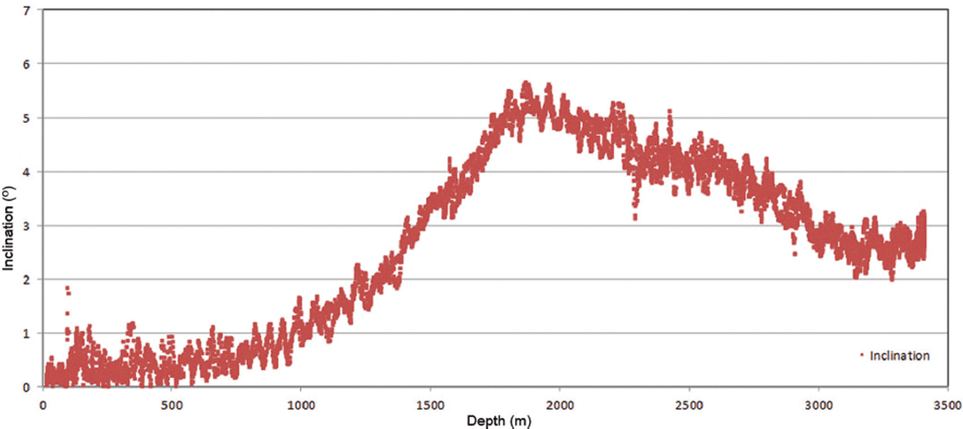
Fig. 26. Parent borehole (WDC06A) inclination, last coring run of 2011/12 season (31 December 2011).
The highlights of the ICDS/IDDO multi-year drilling endeavor using the DISC/replicate coring drill at WAIS Divide include:
-
Accomplishing drilling goals over eight field seasons from 2005/06, when the camp was established and the drill and core-processing arch were erected, to 2012/13 when the replicate coring was successfully completed (Fig. 27)
-
Drilling 3405 m of ice, a new US depth record for ice coring and the second-deepest ice core drilled by any nation
-
New ‘3 for 1’ and ‘2 for 1’ techniques of drilling brittle ice, allowing two or three consecutive ice cores to be drilled and broken before bringing them to the surface and eliminating the need to cut the brittle ice cores on the surface for shipping (Reference SlawnySlawny and others, 2014)
-
First-ever robotic deviation drill
-
Replicate coring: five azimuth and depth-controlled deviations from four target depths (3008 m, 2421 m, 2227m, 1957m) (Fig. 28)
-
285 m of replicate core (first core 17 December 2012)
-
Excellent ductile, brittle, warm and replicate ice-core quality
-
Success is the result of not only good planning and design, but being prepared for the unexpected
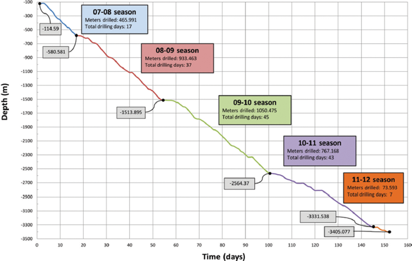
Fig. 27. Ice-drilling progress for borehole WDC06A, parent borehole.

Fig. 28. Ice-drilling progress, replicate borehole.
5.7. Future system development
The American and international science communities are interested in recovering 1 Ma old ice in East Antarctica at an altitude that will likely be >3000 m. The ice thickness would be <4000m. The DISC/RCS appears to be a very good candidate for this mission.
At the time of writing, the drilling site for this endeavor is undetermined and no science proposals for drilling have been submitted. As a result of IDPO (Ice Drilling Program Office) and IDDO’s long-range planning, IDDO will initiate analysis of cryogenic properties of the entire system since the drill sonde will need to operate at –60°C if used in East Antarctica. IDDO also plans to improve the drill system based on its experience at WAIS Divide. Current planning anticipates that the system will be field-ready by the 2018/19 season in Antarctica.
Acknowledgements
During the design, construction, laboratory and field testing and production use of the DISC/RCS, IDDO has had exceptional help and support from many people and organizations. We express our sincere gratitude to them all. In particular, we thank the members of the Ice Drilling Program Office (IDPO) and the IDDO Technical Advisory Board for ongoing advice and assistance; the University of Wisconsin–Madison, particularly the Space Science and Engineering Center, for providing the services of a number of fine engineers, technicians and support staff; the outstanding people of Lockheed Martin (ASC) – the Antarctic Support Contractor for the Replicate Coring Production Season – and Raytheon Polar Services Corporation for all the planning, construction and maintenance of the WAIS Divide facilities; and the NSF Office of Polar Programs for making it all possible. This work was supported under NSF Cooperative Agreement OPP-0841135.


