


1 Introduction
The next generation of particle accelerators for high energy particle physics requires more efficient acceleration methods and more compact machines. One possible way to achieve gigaelectron volt (GeV) energies is plasma acceleration using the strong microelectric fields, called ‘wakefields’, generated by plasma density fluctuations (Tajima & Dawson Reference Tajima and Dawson1979). In AWAKE (Advanced WAKefield Experiment), proton bunches will be used to drive wakefields where electron bunches are subsequently accelerated to the target energies. Electrons can thus be linearly accelerated in a few metres up to multi-GeV energies. The AWAKE project is therefore a crucial step for the development of compact and efficient particle accelerators (Adli et al. Reference Adli, Ahuja and Apsimon2018).
A challenging goal for the development of an AWAKE plasma source is the achievement of an electron density near  $10^{21}~\text{m}^{-3}$, with high homogeneity (better than 0.2 %) over a 10 m plasma cell (AWAKE collaboration 2013). Such a stringent plasma density uniformity is required for wakefield acceleration and electron bunch focussing (Plyushchev et al. Reference Plyushchev, Kersevan, Petrenko and Muggli2018). Moreover, the electron temperature has to be kept below a few eV, since high electron temperatures tend to destroy the accelerating structure of the wakefield. A Rb vapour source was successfully employed to achieve the acceleration of electrons in the plasma wakefield generated by proton bunches (Adli et al. Reference Adli, Ahuja and Apsimon2018). This kind of source, however, requires a laser pulse to convert the gas into a plasma. Helicon plasma cells are a promising candidate to generate the plasmas needed for AWAKE. Their main advantage is that they can produce elongated and centrally peaked plasma columns with high density (maximum achieved steady state is ${\sim}10^{20}~\text{m}^{-3}$) and a few eV electron temperature. The target density for AWAKE is $7\times 10^{20}~\text{m}^{-3}$ and it is suggested that helicon could reach such a target density. Still, some limitations due to neutral pumping, preventing heating of the plasma centre, have to be fully investigated (Buttenschon, Fahrenkamp & Grulke Reference Buttenschon, Fahrenkamp and Grulke2018).
Thomson scattering (TS) is a well-established technique to measure electron density and temperature in plasmas, including those sustained by helicon waves (Seo et al. Reference Seo, You, Kim, b, Shin and Chang2013; Biewer & Shaw Reference Biewer and Shaw2014; Biewer et al. Reference Biewer, Meitner, Rapp, Ray and Shaw2016; Bozhenkov et al. Reference Bozhenkov, Beurskensa, Dal Molinb, Fucherta, Pascha, Stoneking, Hirscha, Hofela, Knauera and Svenssona2017). It is routinely used in tokamak research to obtain electron density and temperature profiles in the plasma core where the density reaches approximately  $2\times 10^{20}~\text{m}^{-3}$ and the temperature several keV (Pasqualotto et al. Reference Pasqualotto, Nielsen, Gowers, Beuskens, Kempenaars, Carlstrom, Johnson and Contributors2004; Pitzschke Reference Pitzschke2011). In this work, we tested a TS diagnostic in a helicon plasma produced by a resonant antenna in a birdcage geometry (Guittienne, Chevalier & Hollenstein Reference Guittienne, Chevalier and Hollenstein2005). Helicon devices can sustain plasma discharges up to an electron density of $n_{e}\approx 10^{19}~\text{m}^{-3}$ and low electron and ion temperatures with a few kW power. In these regimes Langmuir probes (LPs) suffer strong heating and, moreover, electrons are strongly affected by magnetic fields, making measurements unreliable. In the Rb vapour source for AWAKE, the electron density was indirectly estimated by measuring the Rb gas pressure and considering the ionization of all Rb atoms in the laser beam volume (Plyushchev et al. Reference Plyushchev, Kersevan, Petrenko and Muggli2018). The only way to directly measure plasma density in such high density regimes is to employ active or passive spectroscopic techniques which are far less invasive, such as TS. The advantages of TS diagnostics are: (i) measurements of local quantities; (ii) time resolution of the order of the laser pulse duration; (iii) interpretation of the signal reflects the velocity distribution of the particles without requiring any collisional-radiative code. The scattering signal is proportional to the number of the electrons scattering the electromagnetic pulse, therefore high density plasmas are well adapted. This makes argon plasma suitable to test the TS diagnostic since high degrees of ionization can be easily achieved with a few kW power on helicon devices. The resonant antenna ion device (RAID) represents a suitable testbench for a TS diagnostic for the AWAKE project, since helicon plasma columns in Ar can be easily produced at relative high densities ( $10^{19}~\text{m}^{-3}$).
This work describes the design, the calibration and the commissioning of a TS diagnostic on RAID which could be employed for the AWAKE helicon plasma cell. Section 2 describes the design of the TS experimental set-up including the description of RAID, the relative calibration of the polychromators, the absolute Raman calibration in nitrogen gas and the precautions to mitigate the problem of undesired ‘stray light’. Section 3 presents the measurements performed in steady-state argon plasma discharges. Section 4 discusses the physics and technical challenges of the implementation of the present TS system in AWAKE scenarios. In § 5 we conclude with a summary and possible improvements.
2 Implementation of Thomson scattering diagnostic on RAID
RAID is a linear plasma device developed at the Swiss Plasma Center of Ecole Polytechnique Fédérale de Lausanne for negative ion studies for fusion (Marini et al. Reference Marini, Agnello, Duval, Furno, Howling, Jacquier, Karpushov, Plyushchev, Verhaegh and Guittienne2017; Agnello et al. Reference Agnello, Barbisan, Furno, Guittienne, Howling, Jacquier, Pasqualotto, Plyushchev, Andrebe and Béchu2018) and for basic plasma physics investigations (Furno et al. Reference Furno, Agnello, Fantz, Howling, Jacquier, Marini, Plyushchev, Guittienne and Simonin2017). A schematic of the RAID main components is shown in figure 1. The vacuum vessel is a cylinder 1.5 m long and 0.4 m wide. It is surrounded by six water-cooled electromagnets able to produce a magnetic field up to 800 G along the mechanical axis of the vessel and 30 G in the centre of the antenna. A steady-state plasma column is sustained by the propagation of helicon waves launched by a birdcage antenna (Guittienne et al. Reference Guittienne, Chevalier and Hollenstein2005) operating at a frequency of 13.56 MHz. The plasma column ends on a water-cooled, electrically floating, copper target covered with a thin foil of molybdenum to minimize ion sputtering. RAID can sustain a variety of plasma discharges including  $\text{H}_{2}$, $\text{D}_{2}$, relevant for fusion studies as well as $\text{He}$, $\text{Ar}$, $\text{N}_{2}$ and $\text{Ne}$ for wider plasma physics investigations (Thompson et al. Reference Thompson, Agnello, Furno, Howling, Jacquier, Plyushchev and Scime2017). In this paper we will discuss only Ar plasmas, which are more suitable to test the TS diagnostic, since a larger number of photons are scattered, due to the higher densities compared to other gases. Moreover, high- $Z$ gases (where $Z$ is the atomic number) are preferred for plasma acceleration, to minimize the background plasma motion (Vieira et al. Reference Vieira, Fonseca, Mori and Silva2018). Testing the TS in RAID can help in assessing the possibility of using this technique for AWAKE in terms of accuracy, spatial resolution and the technical design of a TS diagnostic. A major difference between RAID and AWAKE is that, while RAID produces a steady-state plasma column, AWAKE is a pulsed plasma device where discharges last a few ms (Buttenschon et al. Reference Buttenschon, Fahrenkamp and Grulke2018). The vacuum flight tubes for the laser beam used for Thomson scattering shown in figure 1 are 1.1 m from the centre of the antenna. At their extremities, windows tilted at the Brewster angle are installed. The TS probing photons are produced by a Q-switched Nd:YAG Lambda laser of 1064 nm wavelength, 0.8 J pulse energy, 6 ns pulse duration and 10 Hz repetition rate. The laser beam exits the laser head with a diameter of $8~\text{mm}$, a divergence ${<}0.5~\text{mrad}$ and a pointing stability ${<}50~\unicode[STIX]{x03BC}\text{rad}$. The alignment of the Nd:YAG laser beam is performed with a He–Ne laser (632 nm) collinear with the Nd:YAG. In figure 2, the positioning of the laser beam path with respect to the RAID vessel is shown. The trajectory of the Nd:YAG beam is then checked with flash paper for fine adjustments. The laser is mounted on an optical table close to the vessel and the frame supporting the laser beam path is free standing from the vacuum vessel to minimize mechanical vibrations caused by pumping and cooling systems. The laser beam is directed to the vessel by mirror M1, then vertically directed by M2 and finally it enters vertically from the top of the vessel after having been steered by mirrors M3 and M4. Before entering the vessel, the laser beam is focused so that its diameter is $1~\text{mm}$ at the measurement position. This is to increase the density of photons in the interaction volume. After the beam waist, the beam expands, exits from the bottom window and is collected in the beam dump, made of multiple tilted glass plates. The vacuum flight tubes on the top and bottom of the cylindrical vessel are 50 cm long and 11 cm wide.
Schematic of RAID showing the position of the Thomson scattering vacuum flight tubes with respect to the antenna position.

Laser path and optical arrangement of the Thomson scattering diagnostics in RAID (not to scale). Before entering the vacuum vessel, the beam is focused by lenses and passes through a window tilted at the Brewster angle to minimize back reflections.

The light collection optics consist of camera lenses  $(f/10)$ pointing towards the centre of the vessel to the plasma column and the line of sight is perpendicular to the laser beam. The collection lenses image an array of four 1 mm diameter glass optical fibres in the plasma column. The diameter of each light spot is 4 mm at the centre of the plasma column. The intersection of the laser beam and the line of sight of the fibres defines the photon collection volume and thus the volume resolution of the system. The vertical spatial resolution with 4 fibres is then 16 mm. If fewer fibres are used, the spatial resolution increases but the signal-to-noise ratio decreases. The length of the optical fibres is $10~\text{m}$ so that the signal is delivered outside the laser interlock area. The scattered light is sent to a polychromator, described in § 2.1, where it is analysed.
To accurately estimate the electron temperature and density, two kinds of calibrations are required: (i) a relative calibration of the spectral transmissivity of the polychromator’s filters and (ii) an absolute calibration using Raman anti-Stokes lines of nitrogen, performed in situ, namely when the entire setup is installed on the plasma device.
2.1 Relative calibration of the polychromators
In Thomson scattering, the scattered photons are emitted in a spectrum broadened to the red and blue around the laser wavelength, whose width increases with the electron temperature. The scattered power  $P_{s}$ per unit of solid angle $\text{d}\unicode[STIX]{x1D6FA}$ and frequency $\unicode[STIX]{x1D714}$ by a laser beam of power $P_{1}$ is given by (Warner & Hieftje Reference Warner and Hieftje2002)
 $$\begin{eqnarray}P_{s}\,\text{d}\unicode[STIX]{x1D6FA}\,\text{d}\unicode[STIX]{x1D714}=\frac{P_{1}n_{e}Le^{4}}{2\unicode[STIX]{x03C0}m_{e}^{2}c^{4}}\,\text{d}\unicode[STIX]{x1D6FA}\,\text{d}\unicode[STIX]{x1D714}|{\hat{s}}\times ({\hat{s}}\times \hat{e})|^{2}S(\boldsymbol{k},\unicode[STIX]{x1D714}),\end{eqnarray}$$
 where  $L$ is the interaction length between the laser beam and the solid angle viewed by the optical fibres, ${\hat{s}}$ is the unit vector pointing from the interaction volume to the detector, $\hat{e}$ is the unit laser electric field vector, $c$ is the speed of light, $m_{e}$ is the electron mass and $S(\boldsymbol{k},\unicode[STIX]{x1D714})$ is the spectral density function, depending on electron density and temperature (Huang & Hieftje Reference Huang and Hieftje1989). If the TS is incoherent (see § 4 for more details), the number of scattered photons is proportional to electron density. To analyse the spectrum, we employed one of the polychromators developed for the divertor TS diagnostic on TCV (tokamak à configuration variable) (Arnichand et al. Reference Arnichand, Andrebe, Blanchard, Antonioni, Couturier, Decker, Duval, Felici, Galperti and Isoz2019). The technique is based on the fast collection of light during ${\sim}2~\text{s}$ plasma shots (Pitzschke Reference Pitzschke2011; Hawke et al. Reference Hawke, Andrebe, Bertizzolo, Blanchard, Chavan, Decker, Duval, Lavanchy, Llobet and Marlétaz2017). The polychromator collects Thomson scattered photons in a few spectral intervals and consists of a set of interference filters and avalanche photodiodes (APDs). When the light enters the TS polychromator, shown in figure 3, it performs multiple reflections and it is collected by four APDs, through different filters each one selecting a different spectral bandwidth. A schematic of the polychromator spectral calibration set-up is shown in figure 4. The light used to calibrate the polychromator is produced by two sources: a halogen lamp emitting a continuous spectrum and a xenon spectral lamp for the wavelength calibration. The monochromator box, consisting of a movable diffraction grating, selects a narrow wavelength interval, typically $\unicode[STIX]{x1D6FF}\unicode[STIX]{x1D706}=0.15~\text{nm}$. The spectral transmissivity of each filter is measured by sweeping the monochromator wavelength over a wide portion of the spectrum. At the same time, the intensity of the light is measured by a calibrated diode. The monochromator output light is then transported via a fibre bundle to the polychromator to be calibrated. The measured transmissivity of the polychromator filters is shown in figure 5(a). The filters are located in the blue-shifted part of the spectrum, where APDs have higher quantum efficiency. In other TS set-ups, like that on DIII-D, the red-shifted part of the spectrum is sampled as well (McLean et al. Reference McLean, Soukhanovskii, Allen, Carlstrom, LeBlanc, Ono and Stratton2014).
Since for RAID plasmas the electron temperature is below 5 eV, only two filters close to 1064 nm collect photons. Therefore, the estimate of the electron temperature is based on the ratio between the light intensity collected by filters F1 and F2 (so the filters F3 and F4 are actually redundant for RAID plasma regimes). The response function of the polychromator used for the present experiment is shown in figure 5(b). One issue regarding the proximity of these filters to the laser wavelength is their residual sensitivity around the laser wavelength. Although the transmissivities of F1 and F2 decay respectively by 4 and 5 orders of magnitude at 1064 nm compared to the peak transmissivity, the number of 1064 nm photons collected by F2 is comparable to that of the TS photons. These laser photons collected by the filters represents a sort of filter leakage and are subtracted in data analysis.
Schematic of the polychromator. The TS light coming to the input is measured by four APD detectors, each one in a well defined spectral range selected by the filters. Reproduced from Arnichand et al., New capabilities of the incoherent Thomson scattering diagnostics in the TCV tokamak: divertor and real-time measurements, 2019 JINST 14 C09013, p. 3, with permission of the authors and IOP Publishing.

Schematic of the spectral calibration system for the polychromator.

(a) Transmission characteristics for the four bandpass filters (F1, F2, F3 and F4) of the TS polychromator. The laser wavelength at 1064 nm, indicated by the black line, is scattered as a spectrum and collected by the filters. (b) Polychromator calibration curve calculated using  $S(k,\unicode[STIX]{x1D714})$ used to determine $T_{e}$. Only three ratios are shown for clarity. In the present set-up only the ratio F2/F1 is used since filters F3 and F4 collect negligible light when $T_{e}<5~\text{eV}$.

2.2 Absolute calibration with Raman anti-Stokes lines
As described in § 2.1, the  $T_{e}$ measurements only require the relative calibration of the spectral channels. To determine $n_{e}$, however, one has to know the absolute transmission efficiency of all the system such as the optics, the polychromators and the emission volume. Therefore, an absolute in situ calibration is needed for every plasma measurement. The rotational anti-Stokes lines of nitrogen are routinely used for the absolute calibration, this technique is commonly used for TS in large fusion devices (LeBlanc Reference LeBlanc2008; Scannell et al. Reference Scannell, Beurskens, Kempenaars, Naylor, Walsh, O’Gorman and Pasqualotto2010). The anti-Stokes part of the nitrogen spectrum is composed of narrow lines, mostly located in the region of the spectrum covered by filters F1 and F2, as shown in figure 6(a). Since broadband filters are used to detect the Raman signal, we use an ‘effective’ cross-section, $\unicode[STIX]{x1D70E}_{\text{eff}}^{\text{RAM}}$, given by the integral of the discrete line weighted by the local filter transmissivity (Franke Reference Franke1997)
 $$\begin{eqnarray}\unicode[STIX]{x1D70E}_{\text{eff}}^{\text{RAM}}=\mathop{\sum }_{n=1}^{N}\unicode[STIX]{x1D70F}(\unicode[STIX]{x1D706}_{n})\unicode[STIX]{x1D70E}_{\text{N}_{2}}^{\text{RAM}}(\unicode[STIX]{x1D706}_{n}),\end{eqnarray}$$
 where  $\unicode[STIX]{x1D70F}(\unicode[STIX]{x1D706}_{n})$ is the transmissivity at the wavelength of the $n$th Raman line and $\unicode[STIX]{x1D70E}_{\text{N}_{2}}^{\text{RAM}}$ the Raman scattering cross-section for $\text{N}_{2}$. A Raman calibration is performed by filling the vacuum chamber with nitrogen with 4 different gas pressures in the interval 20–70 mbar. This range is low enough to avoid laser-induced breakdown in the gas which occurs at ${\sim}100~\text{mbar}$.
(a) Location of the anti-Stokes Raman lines with respect to the filters’ transmissivity. (b) Raman calibration data obtained with filter 1 and filter 2, and linear fits of the experimental data. Each data point is averaged over 700 laser pulses.

Figure 6(b) shows the results for the Raman calibration for F1 and F2. Each data point is averaged over 700 laser shots. The typical error on the determination of the slope is a few per cent. The offset does not affect the estimate of  $n_{e}$, since the Raman calibration factor only depends on the slope. The large difference of vertical offsets between the two filters (0.37 V for F2, 0.01 V for F1), is due to the much higher level of leakage photons collected by F2. Thus, we opted to use F1 for all the Raman calibrations, since less affected by leakage light.
Since the wavelength resolution of the spectrometer employed to calibrate the filters is 0.15 nm wide, this may result in a shift of the filter F1 and F2 with respect to the Raman lines. In the case of F1, which is used for the Raman calibration, this would result in a systematic error  ${<}8.5\,\%$. Since its exact value cannot be known a priori, we have not considered this error in the data analysis for clarity.
2.3 Mitigation of stray light and leakage photons
One of the major challenges of TS diagnostics is the mitigation of the ‘stray light’, which is composed of unwanted errant laser photons collected by the filters together with Thomson scattered photons. With 0.8 J and 1064 nm, there are  $4.3\times 10^{18}$ photons emitted per laser pulse. Only a small fraction of these photons is detected by the system, which is given by multiplying together the photons in the pulse, the Thomson scattering total cross-section, the electron density, the length of the scattering volume, the fractional collection solid angle, the efficiency of transmission of the different optical components and a factor 0.5 since the polychromator detects only the blue-shifted photons. For our system we expect ${\sim}10^{5}$ scattered photons. Because of this relatively small number, the stray light coming from the laser is the main factor limiting the signal-to-noise ratio. These photons come both from internal reflections in the vacuum vessel and the flight tubes and also from the laser path outside the vessel. These are usually distinguished from the leakage photons through the filters at the laser line. To mitigate the noise due to stray photons, the interior of the vacuum chamber in front of the collection optics was covered with Aktar Spectral Black foil, reducing the stray light by approximately 50 %. The residual stray light signal was subsequently subtracted in data analysis. The widespread solution to drastically limit the number of stray photons is to install ‘light baffles’ in the vacuum flight tubes (Carlstrom et al. Reference Carlstrom, Hsieh, Stockdale, Nilson and Hill1997). These prevent the diffusion of stray photons in the vacuum vessel. One possibility to reduce the stray leakage photons through the filters at the laser line would be to shift the position of sensitivity regions of filters F1 and F2 far from the laser wavelength. This would in turn increase the signal-to-noise ratio of the system. This could be done by tilting the filters a few degrees, since the transmissivity depends on the angle of incidence of light of filters. Otherwise new filters with higher rejection at the laser wavelength should be employed (Vincent et al. Reference Vincent, Tsikata, Mazouffre, Minea and Fils2018). The drawback of these approaches is that this would require a re-design of the polychromator optics.
Time resolved  $T_{e}$ and $n_{e}$ in the plasma column centre (spatial resolution of 16 mm) over 100 s, corresponding to 1000 laser shots. The blue spots are the measurements for each laser pulse, the red lines are the error bars on the single measurements and the black line is the moving average over 15 laser pulses.

Electron density and temperature as a function of RF power for different magnetic fields in the centre of the plasma column measured by TS diagnostic. The spatial resolution is 16 mm.

3 Experiments in argon plasmas
For the preliminary tests, to find the highest possible signal-to-noise ratio, we employed all the available optical fibres (4 fibres) and directed them to the plasma centre, where  $n_{e}$ peaks and therefore the highest yield of laser photons is scattered. Figure 7 shows time-resolved measurements of electron density and temperature during a 100 s plasma discharge in Ar with 5 kW RF (radio frequency) power and 665 G magnetic field on axis, and the laser pulsed at 10 Hz. The typical relative error for a single shot is 25.2 % on $T_{e}$ and 17.6 % on $n_{e}$. For magnetic fields above 530 G, the typical ‘blue core’ (Scime, Kesee & Boswell Reference Scime, Kesee and Boswell2008), which we will discuss later on, is observed in visible light, resulting in a narrow peaked brighter region in the plasma centre. The average values of $n_{e}$ and $T_{e}$ during the steady-state plasma discharge are
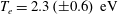
  $n_{e}=1.10\times 10^{19}~\text{m}^{-3}$ and $T_{e}=2.3~\text{eV}$, and we remark that $n_{e}$ and $T_{e}$ are stable during the plasma discharge, therefore, the error bars could be reduced if we would average over many laser pulses. Once we had verified that the signal-to-noise was tolerable, we performed a scan in RF power and magnetic field. Figure 8 shows the electron density and temperature when increasing the RF power and for different magnetic fields; $n_{e}$ increases with the RF power from $5\times 10^{18}~\text{m}^{-3}$ to $1.1\times 10^{19}~\text{m}^{-3}$ for 665 G of the main magnetic field; $T_{e}$, however, is weakly dependent on RF power, as expected by particle balance considerations (Lieberman & Lichtenberg Reference Lieberman and Lichtenberg2005). To improve the volume resolution of the system we employed only two optical fibres, resulting in a spatial resolution of 8 mm. The collection optics were mounted on a translation stage fixed on a vessel flange, and the plasma column was scanned with 10 mm steps in the vertical direction. For each position, a Raman calibration was done (and stray $+$ leakage light measurements were made); this required the vessel filling with nitrogen and pumping to the base pressure for plasma measurements. Figure 9 shows the radial electron density and temperature profiles of the plasma from $-50~\text{mm}$ (below the centre) to 40 mm above the centre. These measurements were performed from 1 to 5 kW of power with 1 kW step size, and for four values of magnetic fields. Electron density profiles show a hollow profile when the magnetic field is ${\lesssim}500~\text{G}$, while the small peak at $B=665~\text{G}$ at 5 kW is the effect of the presence of the blue core. For all magnetic fields, the electron temperature profiles are in the range between 2 and 3 eV. The electron temperature profiles measured in RAID exhibit similar features to those measured in proto-MPEX by double Langmuir probes and a Thomson scattering, showing an approximately flat $T_{e}$ profile in the centre of the plasma column (Goulding et al. Reference Goulding, Caughman, Rapp, Biewer, Bigelow, Campbell, Caneses, Donovan, Kafle and Martin2017; Rapp et al. Reference Rapp, Owen, Canik, Lore, Caneses, Kafle, Ray and Showers2019). The double peak profile for $n_{e}$ and $T_{e}$ in figure 9 for low magnetic fields, $B=200~\text{G}$ and $B=330~\text{G}$, may be a hint of neutral depletion. The observation of hollow profiles consequently triggered the development of a LIF (laser-induced fluorescence) system in RAID to measure the absolute density of a metastable state of neutral helium atoms also of interest to understand the physics of the AWAKE helicon cell. Another process that could be invoked to justify the double peak may be the power dissipation mechanism of the helicon waves along the plasma column. Evidence of the propagation of a helicon wave was measured in RAID by a B-dot probe (Jacquier et al. Reference Jacquier, Agnello, Duteil, Guittienne, Howling, Plyushchev, Marini, Simonin, Morgal and Bechu2019). Numerical simulations are currently underway to investigate how the helicon wave power produced by the birdcage antenna is transferred to the plasma, depending on gas pressure, electron density and boundary conditions.
Electron temperature (a) and density profiles (b) in a steady-state Ar plasma at 0.3 Pa measured by the Thomson scattering diagnostic (spatial resolution 8 mm). Starting from left  $B=200$, 330, 530 and 665 G. Data points are interpolated with cubic splines.

Set-up showing the microwave interferometer (mw) modules and the LP. The mw transmitter shines a microwave beam through the centre of the plasma column (the red lines show the mw beam envelope). The LP describes an arc passing through the centre of the column to determine the plasma column density radial profile.

The  $I_{\text{sat}}$ radial profile of the Ar plasma column when the LP is biased at $-27~\text{V}$. By increasing the magnetic field, the plasma column becomes sharper. These profiles are used to estimate the FWHM of the column and so the length over which the line-integrated density measured by the interferometer is averaged.

The measurements performed in RAID demonstrate that the current TS set-up can be successfully employed to measure  $n_{e}$ down to $4\times 10^{18}~\text{m}^{-3}$ and $T_{e}$ down to 2 eV in a plasma column sustained by helicon waves. In § 4 we discuss the physics and technical constraints of a TS diagnostic in AWAKE concerning the scattering regime and a first schematic design. To cross-check the TS results for $n_{e}$ we employed a combination of a LP (Langmuir probe) and microwave interferometer. The interferometric set-up is shown in figure 10: a microwave transmitter shines a microwave beam though the centre of the plasma column and the receiver measures the phase shift due the presence of plasma. This is used to obtain the measurement of the line-integrated electron density. In parallel, the LP is used to measure plasma $I_{\text{sat}}$ profile to estimate the diameter of the plasma column. The LP tip (8 mm length and 0.4 mm diameter) rapidly passes ( ${<}1~\text{s}$) through the centre of the plasma, measuring $I_{\text{sat}}$, which is approximately proportional to the electron density. Indeed, owing to the high electron density, the LP cannot measure IV (current–voltage) curves, due to excessive thermal flux. Figure 11 shows the $I_{\text{sat}}$ profiles when the probe is biased at $V_{\text{bias}}=-27~\text{V}$ for different RF powers and magnetic fields. Note the effect of the magnetic field steepening and shrinking the plasma column, which is also visible in TS $n_{e}$ profiles in figure 9. We also remark that the relative magnitude of the $I_{\text{sat}}$ plateaux compared between different powers appears consistent with the TS measurements in figure 9. The FWHM (full width at half maximum) of the plasma column is estimated by using these profiles. This, in turn, determines the length over which the line-integrated density by the microwave interferometry is averaged. We note that the shape of the TS $n_{e}$ profiles look like LP $I_{\text{sat}}$ profiles, the difference in shape might be due to the convolution effect of the TS measurements over a 8 mm range and the thermal noise in the LP. The presence of hollow profiles might be due to a combination of different effects such as the local topology of the helicon wave depositing its energy into the plasma and the neutral depletion preventing further ionization in the plasma core. Figure 12 compares the results for $\langle n_{e}\rangle$ measured by microwave interferometry and TS with same plasma conditions in the centre of the plasma column. The two techniques result in comparable values of electron density. The comparison of $T_{e}$ with LP would require us to perform IV sweeps, but this is not possible to perform in this plasma due to the high density and the non-negligible electron magnetization.
Line-averaged  $n_{e}$ measured by interferometry (solid lines) and $n_{e}$ measured by TS (dashed lines) from figure 8, in the centre of the plasma column.

4 Thomson scattering diagnostic in AWAKE
In this paragraph we study the feasibility of employing the TS set-up for RAID in AWAKE, including physics and technical constraints. One main issue concerning the application of the TS apparatus developed on RAID to AWAKE is the range of validity of the incoherent scattering theory assumed for the RAID measurements. This is discussed as follows. TS describes the interaction of plasma free electrons with low energy photons ( $h\unicode[STIX]{x1D708}\ll m_{e}c^{2}$). However, in plasmas, charged particles can interact with each other when their distance is smaller than the Debye length. All electrons located inside a Debye sphere are then correlated with each other, and coherent particle behaviour can be observed. If the wavelength of the exciting radiation is comparable to the Debye length, all electrons in the sphere will oscillate coherently in phase, and the scattering will be coherent. In the opposite case, the electrons oscillate independently and the scattering is incoherent. In this case, $T_{e}$ can be estimated by the width of the distribution of scattered photons. Otherwise, the shape of the electron spectral distribution function $S(k,\unicode[STIX]{x1D714})$ has to be known to determine $T_{e}$ and $n_{e}$. The parameter $\unicode[STIX]{x1D6FC}$, also known as the Salpeter parameter (Salpeter Reference Salpeter1960), determines whether the scattering regime is incoherent ( $\unicode[STIX]{x1D6FC}\ll 1$) or coherent ( $\unicode[STIX]{x1D6FC}\gg 1$)
 $$\begin{eqnarray}\unicode[STIX]{x1D6FC}=\frac{\unicode[STIX]{x1D706}_{L}}{\displaystyle 4\unicode[STIX]{x03C0}\unicode[STIX]{x1D706}_{D}\sin \frac{\unicode[STIX]{x1D703}}{2}},\end{eqnarray}$$
 where  $\unicode[STIX]{x1D706}_{L}$ is the laser wavelength, $\unicode[STIX]{x1D703}$ is the angle between the laser beam incident in the plasma and the observation line of sight and $\unicode[STIX]{x1D706}_{D}$ is the Debye length. Depending on $\unicode[STIX]{x1D6FC}$, the shape of the emission spectrum can strongly vary. In figure 13, we show the $\unicode[STIX]{x1D6FC}$ parameter for $\unicode[STIX]{x1D706}_{L}=1064~\text{nm}$ (Nd:YAG laser wavelength) and $\unicode[STIX]{x1D703}=90^{\circ }$ as a function of $n_{e}$ and $T_{e}$. There are two expected working regimes for AWAKE: the high density regime when $n_{e}=7\times 10^{20}~\text{m}^{-3}$, and the low density regime, for which $n_{e}=2\times 10^{20}~\text{m}^{-3}$, they are indicated in figure 13. The electron temperature can vary typically between 1.5 and 2.5 eV, according to global particle and power balance simulations (Buttenschon et al. Reference Buttenschon, Fahrenkamp and Grulke2018). If we take $T_{e}=2~\text{eV}$ as an average value, $\unicode[STIX]{x1D6FC}$ is 0.30 and 0.16 for the high and low density regimes, respectively. This suggests that collective effects begin to appear in the TS spectrum and thus the coherent scattering has to be taken into account to correctly estimate $n_{e}$ and $T_{e}$. When $\unicode[STIX]{x1D6FC}$ increases, emission spectra are deformed with respect to the Gaussian emission spectra previously described, and this has to be taken into account in the estimate of the error. Because of the very different masses between electrons and ions, Salpeter (Reference Salpeter1960) demonstrated that the expression for the spectral density function $S(\boldsymbol{k},\unicode[STIX]{x1D714})$ can be separated into an electron term and in an ion term
 $$\begin{eqnarray}S(\boldsymbol{k},\unicode[STIX]{x1D714})\,\text{d}\unicode[STIX]{x1D714}=\unicode[STIX]{x1D6E4}_{\unicode[STIX]{x1D6FC}}\,\text{d}x_{e}+Z\left(\frac{\unicode[STIX]{x1D6FC}^{2}}{1+\unicode[STIX]{x1D6FC}^{2}}\right)^{2}\unicode[STIX]{x1D6E4}_{\unicode[STIX]{x1D6FD}}(x_{i})\,\text{d}x_{i},\end{eqnarray}$$
where
 $$\begin{eqnarray}x_{e}=\frac{\unicode[STIX]{x1D714}}{kv_{e}},\quad x_{i}=\frac{\unicode[STIX]{x1D714}}{kv_{i}},\end{eqnarray}$$
 $$\begin{eqnarray}\displaystyle & \displaystyle \unicode[STIX]{x1D6E4}_{\unicode[STIX]{x1D6FC}}(x_{e})=\frac{\text{e}^{-x_{e}^{2}}}{|1+\unicode[STIX]{x1D6FC}^{2}W(x_{e})|^{2}\unicode[STIX]{x03C0}^{1/2}}, & \displaystyle\end{eqnarray}$$
 $$\begin{eqnarray}\displaystyle & \displaystyle \unicode[STIX]{x1D6E4}_{\unicode[STIX]{x1D6FD}}(x_{i})=\frac{\text{e}^{-x_{i}^{2}}}{|1+\unicode[STIX]{x1D6FD}^{2}W(x_{i})|^{2}\unicode[STIX]{x03C0}^{1/2}}, & \displaystyle\end{eqnarray}$$
 $$\begin{eqnarray}\displaystyle & \displaystyle \unicode[STIX]{x1D6FD}^{2}=Z\frac{\unicode[STIX]{x1D6FC}^{2}}{1+\unicode[STIX]{x1D6FC}^{2}}\frac{T_{e}}{T_{i}}, & \displaystyle\end{eqnarray}$$
 $$\begin{eqnarray}\displaystyle & \displaystyle W(x)=1-2x\text{e}^{-x^{2}}\int _{0}^{2}\text{e}^{P^{2}}\,\text{d}P-\text{i}\unicode[STIX]{x03C0}^{1/2}x\text{e}^{-x^{2}}, & \displaystyle\end{eqnarray}$$
 where  $\unicode[STIX]{x1D714}$ is the frequency shift with respect to $\unicode[STIX]{x1D706}_{L}$, $x$ can be $x_{e}$ or $x_{i}$, $Z$ is the atomic number, $v_{e}$ and $v_{i}$ are the thermal electron and ion speeds, respectively.
The  $\unicode[STIX]{x1D6FC}$ parameter for $T_{e}=2\,(\pm 0.5)~\text{eV}$ and two $n_{e}$ regimes with $\unicode[STIX]{x1D703}=90^{\circ }$. The target regime for AWAKE density is $n_{e}=7\times 10^{20}~\text{m}^{-3}$ (red dot) resulting in $\unicode[STIX]{x1D6FC}=0.30$. The lower density regime is at $n_{e}=2\times 10^{20}~\text{m}^{-3}$ (red cross) resulting in $\unicode[STIX]{x1D6FC}=0.16$. For this last regime the current system can be employed with a 3.5 % error for $n_{e}$ estimate.

The first term of (4.2) is due to free electron scattering, while the second term is due to the effect of neighbouring ions on electron scattering (Huang & Hieftje Reference Huang and Hieftje1989). When  $\unicode[STIX]{x1D6FC}\ll 1$, electrons behave as if they were free in the plasma (incoherent scattering regime) and the scattered spectrum can be approximated by a Gaussian (see (4.4)). As $\unicode[STIX]{x1D6FC}$ increases, $\unicode[STIX]{x1D6E4}_{\unicode[STIX]{x1D6FC}}(x_{e})$ flattens and two satellite peaks start to appear when $\unicode[STIX]{x1D6FC}>1$. At the same time the central peak due to the ion contribution $\unicode[STIX]{x1D6E4}_{\unicode[STIX]{x1D6FD}}(x_{i})$ increases (Meiden Reference Meiden2011). The total contribution to the scattered photons is given by integrating equation (4.2) over $\unicode[STIX]{x1D714}$. The total spectral density function is then given by
 $$\begin{eqnarray}\int _{\unicode[STIX]{x1D714}}S(\boldsymbol{k},\unicode[STIX]{x1D714})\,\frac{\text{d}\unicode[STIX]{x1D714}}{2\unicode[STIX]{x03C0}}=S_{e}(\boldsymbol{k})+S_{i}(\boldsymbol{k});\end{eqnarray}$$
where
 $$\begin{eqnarray}S_{e}(\boldsymbol{k})=\frac{1}{1+\unicode[STIX]{x1D6FC}^{2}};\quad S_{i}(\boldsymbol{k})=\frac{Z\unicode[STIX]{x1D6FC}^{4}}{\displaystyle (1+\unicode[STIX]{x1D6FC}^{2})\left[\left(1+\unicode[STIX]{x1D6FC}^{2}+Z\left(\frac{T_{e}}{T_{i}}\right)\right.\unicode[STIX]{x1D6FC}^{2}\right]}.\end{eqnarray}$$
 The ion contribution  $S_{i}$ to the total spectrum is much smaller compared to $S_{e}$ even when $\unicode[STIX]{x1D6FC}=0.3$, for which $S_{i}/S_{e}=0.04$, so the ion contribution can be neglected. In the transition range ( $0.1<\unicode[STIX]{x1D6FC}<1$), the electron spectral function cannot be approximated by a Gaussian distribution. In Carlstrom et al. (Reference Carlstrom, Hsieh, Stockdale, Nilson and Hill1997), regarding a TS system in a tokamak, the authors say that for $\unicode[STIX]{x1D6FC}<0.8$ a 20 % error is made by neglecting the collective effect when fitting the data.
We want to study the effect of varying the  $\unicode[STIX]{x1D6FC}$ parameter on the measured ratio $F_{2}/F_{1}$. Figure 14(a) shows the evolution of the electron emission spectrum $\unicode[STIX]{x1D6E4}_{\unicode[STIX]{x1D6FC}}(x_{e})$ when $\unicode[STIX]{x1D6FC}$ is varied from 0 to 1, when $T_{e}=2~\text{eV}$. As $\unicode[STIX]{x1D6FC}$ increases, $\unicode[STIX]{x1D6E4}_{\unicode[STIX]{x1D6FC}}$ flattens and broadens and more light is collected by filter 2. Figure 14(b) shows the ratios as a function of the electron temperature for different values of $\unicode[STIX]{x1D6FC}$. For a given value of the ratio, the ‘real’ temperature decreases as $\unicode[STIX]{x1D6FC}$ increases. Thus, the current TS system overestimates the temperature measurements. Concerning the error on the electron density, we tend to underestimate it by a factor $1/(1+\unicode[STIX]{x1D6FC}^{2})$, since the integrated emission spectrum decreases, as shown by $S_{e}(\boldsymbol{k})$ in (4.9). In the case of RAID, $\unicode[STIX]{x1D6FC}=0.03$, resulting in an error on $T_{e}$ due to the coherent scattering ${<}0.2\,\%$, so, negligible compared to the typical error on the single measurement. For the low density AWAKE regime, for which $\unicode[STIX]{x1D6FC}=0.16$, the contribution to the total error due to the partially coherent scattering regime would be ${\sim}1\,\%$ on $T_{e}$ and ${\sim}2.5\,\%$ on $n_{e}$. Therefore, when comparing two density points, this gives a ${\sim}3.5\,\%$ base uncertainty. For the high density AWAKE regime, for which $\unicode[STIX]{x1D6FC}=0.30$, this value increases to ${\sim}15\,\%$. Table 1 summarizes the discussed scenarios, showing the contribution to the error coming from the partially coherent scattering regime.
(a) Broadening of the electron emission spectrum due to the increasing effect of the coherent regime, for a fixed electron temperature of 2 eV. (b) Ratio of filter signals as a function of electron temperature by varying the  $\unicode[STIX]{x1D6FC}$ parameter.

Contribution of the error due to the partially coherent scattering regime in different scenarios.

The total error on the measurements has to take into account the contribution of all factors such as the electronic noise of APDs, the presence of residual stray light and bremsstrahlung emission. An alternative way to measure  $T_{e}$ and $n_{e}$ would consist of measuring the entire scattered spectrum, to deduce the scattering regime. A Thomson scattering diagnostic with an ICCD (intensified CCD) camera was successfully installed in linear steady-state plasmas (Lee et al. Reference Lee, Lee, Kim and Lho2018). For the upgrading of the current TS system in RAID, a frequency-doubled YAG (532 nm) with a high resolution grating and a high resolution CCD camera for acquisition is envisaged; this would halve the $\unicode[STIX]{x1D6FC}$ parameter. Therefore, a frequency-doubled YAG may be a good compromise between the laser pulse intensity (decreased with respect to 1064 nm) and minimization of $\unicode[STIX]{x1D6FC}$. The measurement of the entire spectrum would also allow us to detect the presence of electron populations with different temperatures Vincent et al. (Reference Vincent, Tsikata, Mazouffre, Minea and Fils2018).
4.1 Considerations for a TS diagnostic in AWAKE
A preliminary schematic design of a TS diagnostic for AWAKE is shown in figure 15. The laser beam is injected along the axis to perform multiple measurements along the entire plasma axis. This requires a lens system able to position the laser beam waist along the axis. The collection optics could be installed on a translation stage to perform axial scans. The already existing two view ports would allow us to compare the density at two axial positions. In the case of a helicon cell with a length comparable to the Rb vapour source ( ${\sim}10~\text{m}$), the positioning of the laser beam waist could be performed by a focusing optics system with variable focal length, such as that used in RAID. The experience acquired with RAID suggests that diaphragms are necessary to strongly reduce the level of stray light caused by multiple reflection in the vessel. Therefore, two sets of five diaphragms at each side of the plasma cell are envisaged. Moreover, to avoid stray light diffusion from the laser beam path outside the cell, the laser beam path should be enclosed. The current TS system in RAID based on polychromators allows us to detect an electron temperature down to ${\sim}1.5~\text{eV}$; a lower temperature would be difficult to detect because of the emission spectrum would be too narrow compared to filters. If this would be the case for AWAKE, narrower filters would be required. Alternatively, a different system to acquire the scattered light should be implemented.
As a further improvement step, a knowledge of the shape of the entire electron emission spectrum would allow us to measure  $n_{e}$ and $T_{e}$. If the AWAKE plasma discharge is reproducible one could rely on statistics and collect a sufficient number of photons to have a value of $S_{e}$ with an acceptable signal-to-noise ratio. This would require us to phase lock the laser with the plasma discharge. By doing some technical adaptations, the current system could be in principle used in AWAKE to perform TS measurements with a contribution to the error coming from the partially coherent scattering regime ${\sim}1\,\%$ on $T_{e}$ and ${\sim}2.5\,\%$ on $n_{e}$ a single measurement location.
Schematic design of a Thomson scattering diagnostic for AWAKE helicon source.

5 Summary and future developments
We have installed and successfully tested a Thomson scattering diagnostic on RAID, as a testbench for AWAKE. We verified that the current system measures electron temperature down to 2 eV and the electron density down to  $4\times 10^{18}~\text{m}^{-3}$. The present TS diagnostic requires a relative calibration of polychromator filters to measure $T_{e}$ and a in situ Raman calibration to determine $n_{e}$. The results in RAID show an electron density $n_{e}=1.10\times 10^{19}~\text{m}^{-3}$ and electron temperature of $T_{e}=2.3~\text{eV}$ in the centre of an Ar plasma discharge with 5 kW RF power. Microwave interferometry and LP measurements are used to cross-check TS results, showing good agreement. We performed radial profiles measurements, showing the effect of the magnetic field.
We presented some preliminary calculations to apply the current TS diagnostic for AWAKE plasma regimes. In AWAKE, the  $\unicode[STIX]{x1D6FC}$ parameter, determining the scattering regime, is located in a transition region where the coherent contribution to the scattering signal cannot be neglected. Finally, we outlined a preliminary schematic design of a TS diagnostic for the AWAKE helicon plasma cell.
Acknowledgements
This work has been carried out within the framework of the EUROfusion Consortium and has received funding from the Euratom research and training programme 2014–2018 and 2019–2020 under grant agreement no 633053. The views and opinions expressed herein do not necessarily reflect those of the European Commission. This work was supported in part by the Swiss National Science Foundation. We gratefully acknowledge the mechanical and electronic workshops of the Swiss Plasma Center for their collaboration.


