


Introduction
Broadband and low-latency communication technologies as well as remote sensing applications enable a broad spectrum of new industry and consumer applications. Systems operating at millimeter wave (mmWave) frequencies and above could enable these technologies but are challenging to develop and produce and therefore not very attractive. Especially electrically steered antenna arrays (ESAs), which are indispensable for mmWave systems, require time-consuming tests and procedures to calibrate and validate their beam steering capabilities [Reference Maggi, Hidri, Marnat, Ettorre, Orozco, Margalef-Rovira, Gaquière and Haddadi1, 2]. State-of-the-art antenna measurement systems (e.g. anechoic chambers and compact antenna test ranges) are too voluminous, expensive, and low throughput for a cost-effective production style unit testing of ESAs [Reference Janse van Rensburg3–Reference Barani, Bronckers and Reniers5]. To solve these problems, we present an active probe array system (PAS), which has been designed for fast and compact over-the-air (OTA) validation and production testing of mmWave ESAs. The presented system captures the near-field (NF) behavior of an ESA without relative movement between the measurement system and the antenna under test (AUT). Using a novel NF OTA measurement method first introduced in [Reference Laabs, Plettemeier, Deckert, Kotzsch and Vanden Bossche6], we are able to reconstruct the beam steering behavior of the ESA in the far field (FF). The active PAS is designed to measure the NF behavior of the AUT with minimal interference and high stability. This is achieved by converting the mmWave frequency band to a lower IF frequency band, thereby making the active PAS more cost-effective and more scalable than traditional state-of-the-art mmWave antenna measurement systems. The presented work is structured as follows: In Section 2, we illustrate, describe, and explain the NF OTA calibration and measurement algorithm used to reconstruct the FF beam steering properties of the AUT from its NF behavior. In Section 3, we will present and discuss the construction of the active PAS. Section 4 will show reconstructed FF beam patterns calculated from the NF measurements of the active PAS and compare them to true FF measurements. Section 5 will give a conclusion and will describe future work related to the algorithm and the active PAS. An earlier version of this work was presented at the EuMC23 conference and was published in its proceedings [Reference Obermaier, Laabs, Deckert and Plettemeier7]. This version of the paper includes a discussion on how the leakage of an AUT can be characterized and compensated, as well as a more detailed description of the measurement and algorithm workflow.
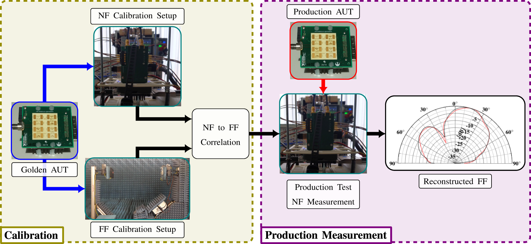
NF and FF measurement setup and correlation
Overview of the algorithm and measurement steps
The measurement algorithm used to reconstruct the FF from NF measurements is structured into four steps. For the first two steps, we require a known golden AUT, which is electrically representative and equal in its mechanical construction to the high-volume product. This golden AUT is used as a reference and allows us to capture the correlation between the FF and NF measurement setup. The first two steps with the golden AUT have to be performed only once and are completely independent of the measurement and reconstruction step during the ESA production. After the NF and FF behaviors of the golden AUT have been correlated, it is possible to reconstruct the FF behavior of production AUTs from NF measurements. The deployed NF measurement setups in step (ii) and step (iv) are identical. The algorithmic steps are structured as follows:
(i) FF calibration measurements of the known golden AUT antenna elements .
(ii) NF calibration measurement and calibration of the PAS requiring the same known golden AUT.
(iii) Correlation of the NF and FF measurements of the golden AUT.
(iv) Reconstruction of the AUT FF behavior based on OTA NF measurements in a high-throughput production environment.
Figure 1 illustrates the workflow of the algorithm. The workflow is structured into two independent sections. During the calibration, the known golden AUT is characterized in an FF and an NF setup (steps (i) and (ii)). The NF and FF measurements taken during these measurements can then be correlated (step (iii)), which allows to relate the OTA NF measurements of the active PAS to FF measurements. During a high volume production measurement, the NF measurement setup can now be used to characterize production AUTs and reconstruct their FF radiation behavior (step (iv)).
Overview of the calibration and reconstruction process.
NF and FF measurement model
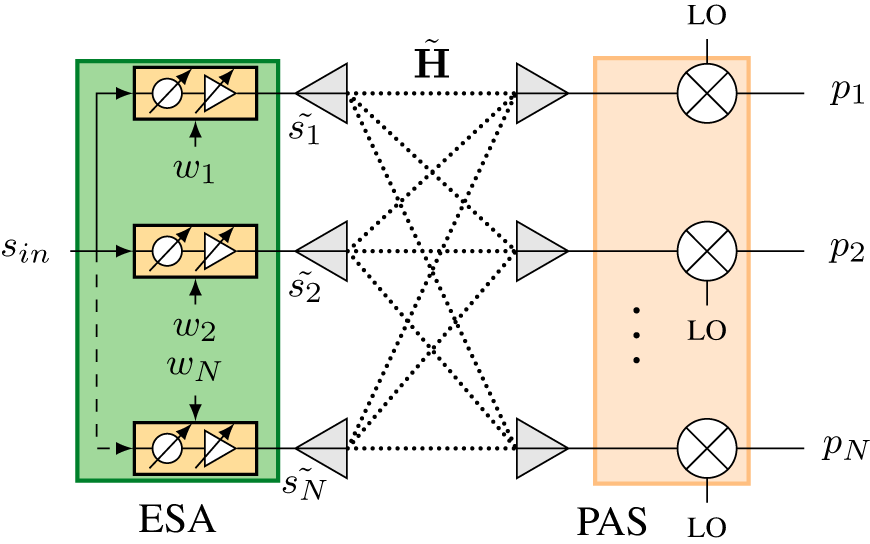
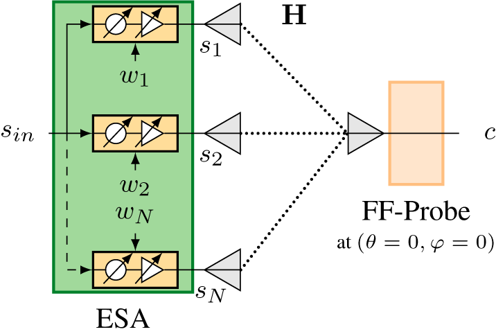
Figures 2 and 3 show representative models of the NF and FF measurement setups. The depicted generic ESA in both setups is constructed from N single element antennas, which are fed by a beam-forming network (BFN). The common ESA input signal sin is distributed to all BFN inputs. The BFN allows to introduce amplitude and phase changes on each channel individually. Each BFN element is controlled by a setting  $w_n=(G_n,\Delta\phi_n)$, which configures the amplification G and phase change $\Delta\phi$ introduced by the element. To simplify the discussion of the following NF and FF measurement setups, we assume a single Continous Wave (CW) signal at the ESA input sin. The overall BFN configuration of the ESA is stored in the beam-forming setting:
 \begin{equation}
\mathbf{w} = \big[w_1:=(G_1,\Delta\phi_1),w_2,\ldots,w_N\big].
\end{equation}
\begin{equation}
\mathbf{w} = \big[w_1:=(G_1,\Delta\phi_1),w_2,\ldots,w_N\big].
\end{equation} The close proximity of the active PAS during the measurement of the NF signals might change the output impedance of the BFN due to capacitive loading. For this reason, we differentiate the BFN output signals to the single element antennas sn in the FF and  $\tilde{s}_n$ in NF setup. In both configurations, we measure the radiated signals from individual single element antennas of the ESA. The propagation between the single element antenna and the probes is described by a linear time-invariant (LTI) channel. This channel is denoted as H in the FF setup and as $\tilde{\mathbf{H}}$ in the NF setup. To allow the PAS to correctly attribute the received signals to the correct single element on the ESA, we require at least as many probes as there are single elements ( $M\geq N$) [Reference Laabs, Plettemeier, Deckert, Kotzsch and Vanden Bossche6]. The FF measurement can be performed by a single probe in bore sight position as shown in Figure 3. The frequency conversion shown in Figure 2 is phase coherent on all channels and independent of the received probe power.
Near-field measurement setup with an N single element antenna ESA and the N NF probes of the active PAS. The PAS is in the radiating NF of a single element antenna.
FF measurement setup with the ESA and a single FF probe oriented in the boresight position. The probe is placed in the FF of the AUT.
FF calibration measurement
The FF calibration and reference measurement capture the FF behavior and characteristics of the golden reference AUT. During this measurement, we capture the pattern  $D_n(\Theta, \Phi)$ of every single element antenna. To exclusively capture the single element patterns, we define N BFN configurations $\mathbf{w_\textit{n}}$, such that only the nth ESA antenna element ( $s_n\neq 0$) is active. The electric field created by the element can then be expressed by the output of the BFN element and the normalized directivity of the the antenna element:
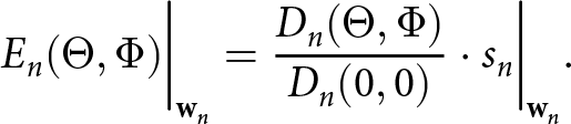 \begin{equation}
E_n(\Theta, \Phi)\bigg|_{\mathbf{w}_n} = \frac{D_n(\Theta, \Phi)}{D_n(0,0)} \cdot s_n\bigg|_{\mathbf{w}_n}.
\end{equation}
\begin{equation}
E_n(\Theta, \Phi)\bigg|_{\mathbf{w}_n} = \frac{D_n(\Theta, \Phi)}{D_n(0,0)} \cdot s_n\bigg|_{\mathbf{w}_n}.
\end{equation} The N boresight measurements  $D_n(0,0)$ would theoretically be sufficient to completely describe the channel H, but by measuring each BFN element at K different gain/phase settings we can improve the accuracy and stability of the NF to FF correlation [Reference Laabs, Plettemeier, Deckert, Kotzsch and Vanden Bossche6]. For these measurements, we define an additional set of BFN configurations $\mathbf{w}_{kn}$. These measurements are only performed in the boresight direction of the AUT, as illustrated in Figure 3
 \begin{equation}
c_{kn} = E_n(0,0)\bigg|_{\mathbf{w}_{kn}}.
\end{equation}
\begin{equation}
c_{kn} = E_n(0,0)\bigg|_{\mathbf{w}_{kn}}.
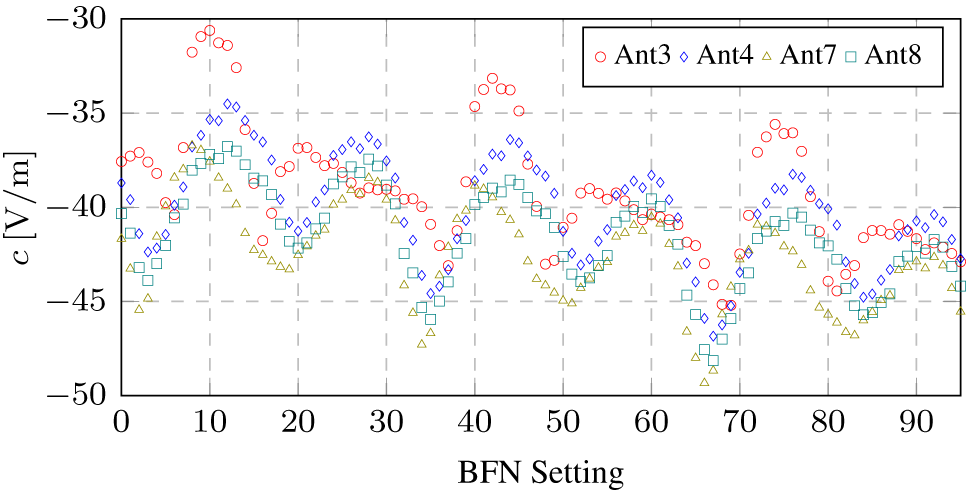
\end{equation} Figure 4 shows the FF calibration measurements of four antenna elements, which are configured for 3 gain and 32 phase steps each. The measurements were performed with the Scarif ESA DUT shown in Figure 6. An ideal ESA would only show three distinct signal levels per element for the three configured gain steps. The oscillations and fading effects seen in Figure 4 are caused by the variable insertion loss of the phase shifters inside the BFN of the ESA and by constructive and destructive interference from leakage effects by other antenna elements. The NF to FF correlation outlined in Section 2.1 is based on the concept of relating the radiated signals of single element antennas in the NF and FF setup. It is, therefore, necessary that  $|s_i| \gg |s_n|$ for n ≠ i, to only capture the effect of the desired antenna element i. If the influence of the surrounding elements is too large, it is necessary to compensate the leakage effects in the measurement. The BFN of the Scarif ESA is able to amplify and phase shift the input stimulus sin but is not able to attenuate the the input signal. To characterize this leakage by the other elements, we can define an Off-pattern. This Off-pattern is defined by the BFN setting w off, which minimizes the gain G and phase change $\Delta\phi$ of all BFN elements. The measurement of the Off-pattern can then be used to compensate the leakage effect:
 \begin{equation}
\tilde{c}_{kn} = E_n(0, 0)\bigg|_{\mathbf{w}_{kn}}-E_n(0, 0)\bigg|_{\mathbf{w}_{\text{off}}}.
\end{equation}
\begin{equation}
\tilde{c}_{kn} = E_n(0, 0)\bigg|_{\mathbf{w}_{kn}}-E_n(0, 0)\bigg|_{\mathbf{w}_{\text{off}}}.
\end{equation}FF measurements of single element antennas 3, 4, 7, and 8 of the Scarif ESA for 3 gain steps and 32 phase settings each.
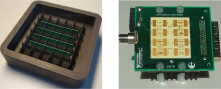
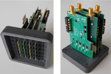
Passive PAS with a 4 × 4 probe antenna array (left) and the corresponding Scarif ESA (right).
NF calibration measurement
The NF calibration measurement is performed using the active PAS and same golden reference ESA, which has been used during the FF calibration measurement. The PAS probes are placed above the single element antennas of the ESA. The distance between the ESA and PAS is chosen such that the PAS probes are in the radiating NF of the individual corresponding single element antennas. The ESA antennas and the PAS probes are strongly coupled as shown in Figure 2. The PAS output signals  $\mathbf{p}= [p_1, \ldots, p_n]$ are linked to the BFN outputs $\tilde{\mathbf{s}}$ by the NF channel $\tilde{\mathbf{H}}$
 \begin{equation}
\mathbf{p} = \tilde{\mathbf{H}}\tilde{\mathbf{s}}.
\end{equation}
\begin{equation}
\mathbf{p} = \tilde{\mathbf{H}}\tilde{\mathbf{s}}.
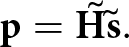
\end{equation} During the NF calibration, all previously defined BFN configurations  $\mathbf{w}_{kn}$ are remeasured with the active PAS. Figure 5 shows the NF measurement of the 96 BFN settings of single element antenna 3. The measurement shows that the majority of the the radiated signal of antenna 3 is received by the adjacent probe of the active PAS. The surrounding probes receive the signal of antenna 3 with a 10–20 dB attenuation.
NF measurements of single element antenna 3 for 3 gain steps and 32 phase settings each.
Unintentional leakage from other antenna elements can be corrected analogously to the FF calibration measurement, by definition of an Off-configuration w off. The definition of this Off-setting needs to be identical to the FF calibration measurement
 \begin{equation}
\tilde{p}_{kn} = p_{kn}-p_{\text{off}}.
\end{equation}
\begin{equation}
\tilde{p}_{kn} = p_{kn}-p_{\text{off}}.
\end{equation} The channels H and  $\tilde{\mathbf{H}}$, the AUT, the FF probe as well as the active PAS can be assumed to act as LTI systems. As such we are able to use the NF and FF calibration measurements to describe these systems and create a linear transformation between the NF and FF measurements [Reference Laabs, Plettemeier, Deckert, Kotzsch and Vanden Bossche6]. We denote such a transformation as reconstruction matrix R:
 \begin{align}
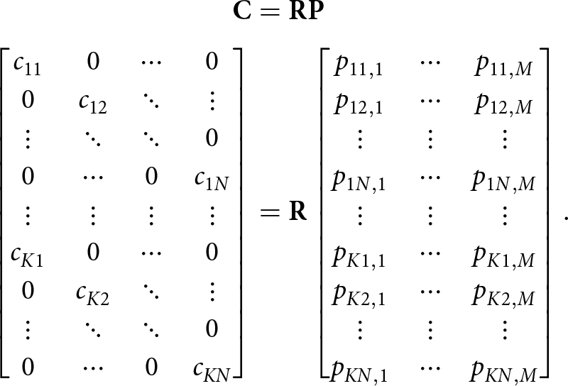
\mathbf{C} &= \mathbf{R} \mathbf{P} \nonumber\\
\begin{bmatrix} c_{11} & 0 & \cdots & 0\\
0 & c_{12} & \ddots & \vdots\\
\vdots & \ddots & \ddots & 0\\
0 & \cdots & 0 & c_{1N}\\
{\Large\vdots} & {\Large\vdots} & {\Large\vdots} & {\Large\vdots} \\
c_{K1} & 0 & \cdots & 0\\
0 & c_{K2} & \ddots & \vdots\\
\vdots & \ddots & \ddots & 0\\
0 & \cdots & 0 & c_{KN}
\end{bmatrix} & =\mathbf{R}
\begin{bmatrix} p_{11,1} & \cdots & p_{11,M}\\
p_{12,1} & \cdots & p_{12,M}\\
\vdots & \vdots & \vdots\\
p_{1N,1} & \cdots & p_{1N,M}\\
{\Large\vdots} & {\Large\vdots} & {\Large\vdots} \\
p_{K1,1} & \cdots & p_{K1,M}\\
p_{K2,1} & \cdots & p_{K2,M}\\
\vdots & \vdots & \vdots\\
p_{KN,1} & \cdots & p_{KN,M}
\end{bmatrix}.
\end{align}
\begin{align}
\mathbf{C} &= \mathbf{R} \mathbf{P} \nonumber\\
\begin{bmatrix} c_{11} & 0 & \cdots & 0\\
0 & c_{12} & \ddots & \vdots\\
\vdots & \ddots & \ddots & 0\\
0 & \cdots & 0 & c_{1N}\\
{\Large\vdots} & {\Large\vdots} & {\Large\vdots} & {\Large\vdots} \\
c_{K1} & 0 & \cdots & 0\\
0 & c_{K2} & \ddots & \vdots\\
\vdots & \ddots & \ddots & 0\\
0 & \cdots & 0 & c_{KN}
\end{bmatrix} & =\mathbf{R}
\begin{bmatrix} p_{11,1} & \cdots & p_{11,M}\\
p_{12,1} & \cdots & p_{12,M}\\
\vdots & \vdots & \vdots\\
p_{1N,1} & \cdots & p_{1N,M}\\
{\Large\vdots} & {\Large\vdots} & {\Large\vdots} \\
p_{K1,1} & \cdots & p_{K1,M}\\
p_{K2,1} & \cdots & p_{K2,M}\\
\vdots & \vdots & \vdots\\
p_{KN,1} & \cdots & p_{KN,M}
\end{bmatrix}.
\end{align} Equation 7 describes the relation between the FF measurements  $\mathbf{C} \in \mathbb{C}^{N\times K}$ with the NF measurements $\mathbf{P} \in \mathbb{C}^{M\times K}$. The channel $\mathbf{H}\in \mathbb{C}^{N\times 1}$ and the requirement that $s_i \gg s_n$ for all i ≠ n during the calibration measurements cause the sparse nature of C. Since there is significant coupling to all the M PAS probes, as seen in Figure 5, P has a dense structure. Equation 7 can be solved for $\mathbf{R}\in \mathbb{C}^{N\times M}$ by linear regression. A least square solution based on the Wiener filter can be calculated by [Reference Laabs, Plettemeier, Deckert, Kotzsch and Vanden Bossche6]:
 \begin{equation}
\mathbf{R} = (\mathbf{PP^H})^{-1} \cdot (\mathbf{PC}^H ).
\end{equation}
\begin{equation}
\mathbf{R} = (\mathbf{PP^H})^{-1} \cdot (\mathbf{PC}^H ).
\end{equation}Active PAS, with 16 NF probes (4 × 4 layout).
Equation 8 is only valid for a single CW frequency. To achieve a broadband transformation between NF and FF measurements, the calibration measurements and correlation steps need to be performed at multiple frequency points.
NF to FF reconstruction
The matrix R, which has been calculated from the FF and NF calibration measurements, allows us to reconstruct the equivalent single element FF stimuli s from the NF measurements p. To ensure that this reconstruction is valid, the channel  $\tilde{\mathbf{H}}$ needs to remain identical to the calibration measurements. Since the golden AUT and the production AUT are constructed identically, this is solely achieved by maintaining the relative position of the AUT and the active PAS. A investigation of the errors caused by position offsets can be found in [Reference Laabs, Plettemeier, Deckert, Kotzsch and Vanden Bossche6]. The FF stimulus s for a BFN setting wi is calculated by:
 \begin{equation}
\mathbf{s}_{\mathbf{w}_i} = \mathbf{R} \cdot \mathbf{p}_{\mathbf{w}_i}.
\end{equation}
\begin{equation}
\mathbf{s}_{\mathbf{w}_i} = \mathbf{R} \cdot \mathbf{p}_{\mathbf{w}_i}.
\end{equation} The captured and normalized single element patterns, which have been captured during the FF calibration measurement, can now be scaled using the reconstructed FF BFN outputs s. The outputs can be superposed to calculate the complete FF pattern of the ESA for a BFN configuration wi. The reconstructed field  $E_{\text{FF}}(\Theta, \Phi)$ is equivalent to a measurement in the FF setup that was used during the FF calibration
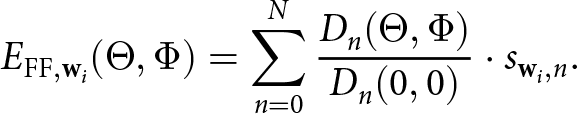 \begin{equation}
E_{\text{FF},\mathbf{w}_i}(\Theta, \Phi) = \sum_{n=0}^{N} \frac{D_n(\Theta,\Phi)}{D_n(0,0)} \cdot s_{\mathbf{w}_i,n}.
\end{equation}
\begin{equation}
E_{\text{FF},\mathbf{w}_i}(\Theta, \Phi) = \sum_{n=0}^{N} \frac{D_n(\Theta,\Phi)}{D_n(0,0)} \cdot s_{\mathbf{w}_i,n}.
\end{equation} Should the ESA show significant leakage it is necessary to add a leakage pattern to the FF reconstruction in order to reconstruct the correct FF. This leakage pattern can be acquired during the FF calibration measurement using the  $\mathbf{w}_{\text{off}}$ configuration
 \begin{equation}
E_{\text{FF},\mathbf{w}_i}(\Theta, \Phi) = \sum\limits_{n=0}^{N} \frac{D_n(\Theta,\Phi)}{D_n(0,0)} \cdot s_{\mathbf{w}_i,n} + E_{\text{Off}}(\theta,\phi).
\end{equation}
\begin{equation}
E_{\text{FF},\mathbf{w}_i}(\Theta, \Phi) = \sum\limits_{n=0}^{N} \frac{D_n(\Theta,\Phi)}{D_n(0,0)} \cdot s_{\mathbf{w}_i,n} + E_{\text{Off}}(\theta,\phi).
\end{equation} The normalized single element patterns in Equation (11) need be adjusted for the leakage of the other single elements. Otherwise, we would also scale the leakage pattern with BFN outputs  $s_{\mathbf{w}_i,n}$ and distort the reconstructed FF pattern.
Construction of the active PAS
The calibration and reconstruction procedure described in Section 2 was originally conceived for a passive PAS without any frequency conversion capability [Reference Laabs, Plettemeier, Deckert, Kotzsch and Vanden Bossche6]. This passive PAS, which is pictured in Figure 6, directly connects to an mmWave measurement device using coaxial cables. The passive PAS is able to implement the described measurement procedures and can reconstruct the ESA FF behavior but shows some imperfections, which makes it unsuitable as a production measurement device. The direct cable connection of the probes to the mmWave measurement instrumentation introduced unpredictable phase changes during every AUT switch. This violates the fundamental assumption of Section 2 that the NF measurement setups remain unaltered between calibration and measurement.
The introduced phase changes caused increasingly severe FF reconstruction errors. The passive PAS was also very limited by the required number of mmWave channels. Measurement equipment, which would allow the passive PAS to characterize ESAs with more than 16 single element antennas, would be very challenging to implement and costly. The active PAS was constructed to address and solve these problems. The active PAS reuses the probe structure and casted absorber of the passive PAS, as seen in Figure 7, and adds a frequency conversion and filtering stage after each probe. The mmWave signals are directly converted to frequencies below 10 GHz and are no longer subject to the same phase drifts during the switch of the AUT. The resulting IF band still provides enough bandwidth to completely characterize broadband mmWave signals. The acquisition of the probe signals at these frequencies is also much more economical and can be scaled to an arbitrary number of channels. The active PAS is constructed from four individual PCBs with four conversion channels each. Figure 8 shows the layout and construction of an active PAS PCB. The active PAS uses a four-layer Printed Circuit Board (PCB) stackup in order to route the Radio Frequency (RF), Intermediate Frequency (IF), and power connections. The Vivaldi antennas, which are used as probes, have the advantage of already containing a Balun structure as well as being relatively broadband. The probes are realized using an internal copper layer of the PCB stackup.
Interfaces and layout of an active PAS PCB.
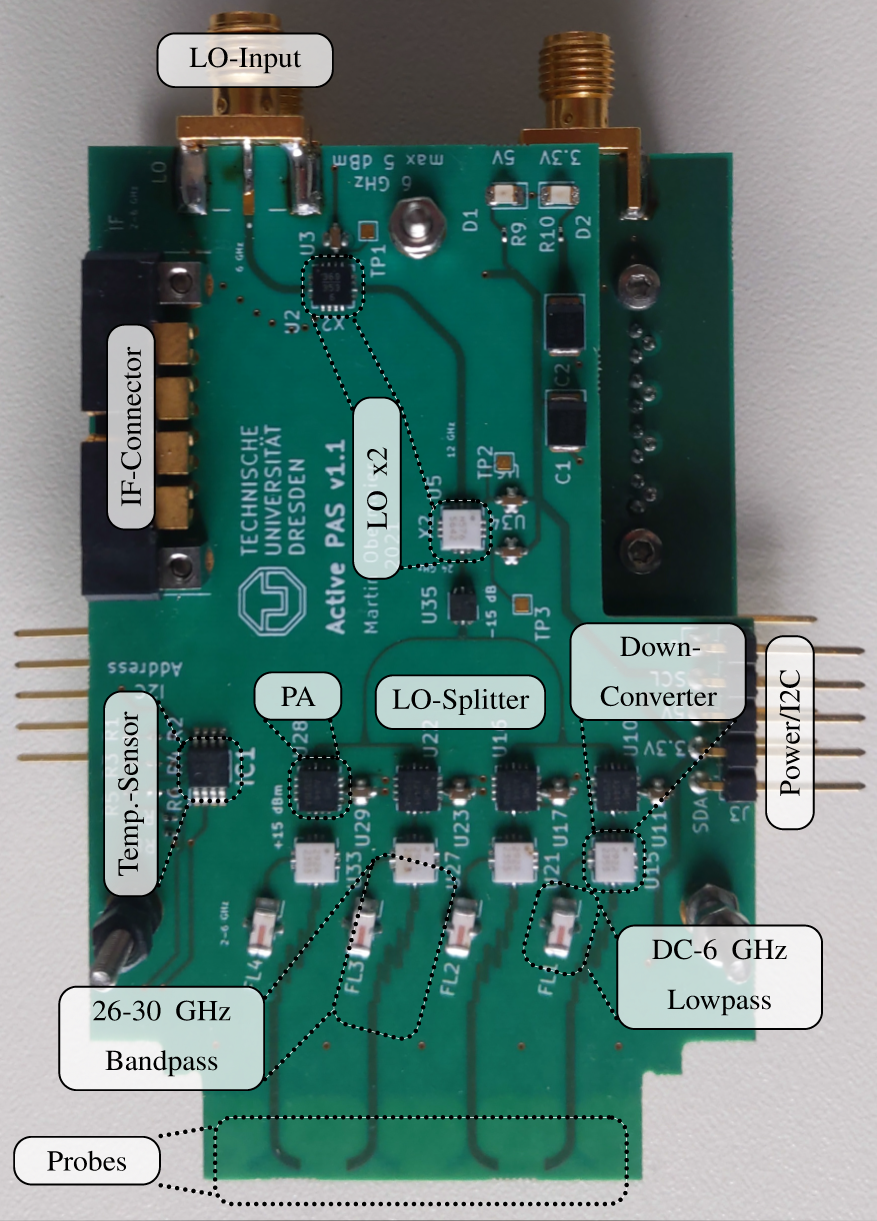
The remaining PCB material of the stackup below the probes is removed using an abrasive process, before the PCBs are populated. To maximize the isolation between adjacent probes, every second PAS PCB is flipped by 180∘. The notch cutout at the top right ensures that the PAS PCBs can be spaced close enough together to match the ESA element antenna layout. This is necessary since the height of the IF connector is greater than the required spacing. Each probe is connected to a passive double balanced mixer via a band-pass filter, which has been realized by coupled micro-strip lines. This filter limits the RF mixer input to 26–30 GHz, while simultaneously increasing the Local Oscillator (LO) to RF isolation by 10 dB. Since the passive double balanced mixers need a relatively strong LO signal of 15 dBm, a leakage from the LO to the probes could radiate back to the ESA. The radiated signal could create a nonlinear impedance change at the output of the BFN, which would violate the LTI assumption at the basis of the NF to FF transformation. The active PAS uses passive mixers to ensure a high linearity over the RF input power. The IF output of each mixer is connected to a low-pass filter, which removes mixing components above 6 GHz and then routed on an internal copper layer to the IF connector at the top left of the PCB.
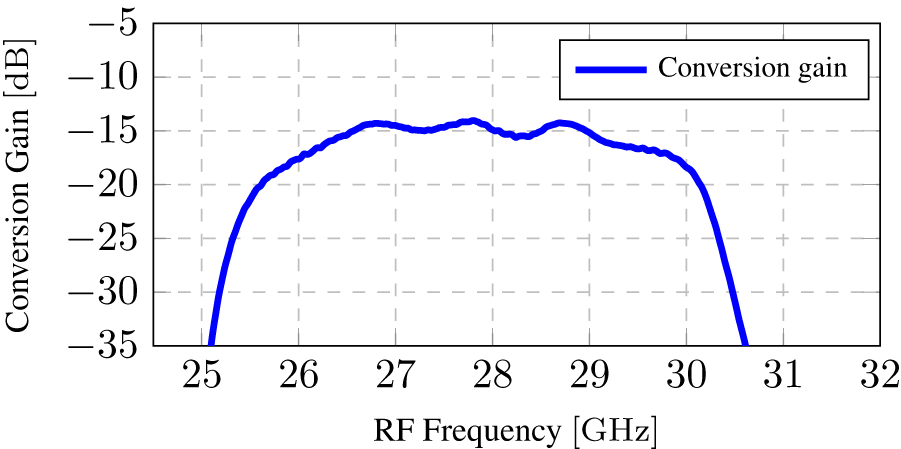
A fundamental task of the active PAS is the generation and distribution of the LO, to ensure the coherent frequency conversion of all mmWave probe signals to the IF band. Each PAS PCB is supplied with a coherent 6 GHz signal, which is first multiplied to 12 GHz and then 24 GHz. The LO signal is then evenly split and distributed to each of the four conversion channels. A power amplifier at each mixer ensures an LO power of 15 dBm. The active PAS is designed to convert the RF band 26–30 GHz to an IF band of 2–6 GHz. The frequency conversion introduces losses, since the PAS uses passive mixers. Figure 9 shows a measurement of the conversion gain of one active PAS channel. This measurement has been performed on a PAS PCB with coaxial connectors instead of NF probes. Figure 9 also shows that besides the conversion loss we also experience a slight ripple in the pass band. Since all these effects are systematic, they can be incorporated during the NF-Calibration-step without any adjustment to the described algorithm in Section 2. We will experience a degradation of the Signal-To-Noise Ratio (SNR) based on the conversion loss, but this loss is very reasonable compared to the effects of free space attenuation and cable losses in traditional FF or NF measurement setups [Reference Walkenhorst4]. To monitor the temperature of the PAS, a temperature sensor was placed on each PCB, which is thermally connected to the mixers by a ground plane. The complete active PAS with its absorber has a size of only 7 cm × 7 cm × 10 cm.
Conversion performance of an active PAS channel.
FF beam reconstruction
Figures 10 and 11 show the measured and reconstructed vertical cuts of two different beam settings of the Scarif ESA at 27.2 GHz and 28.8 GHz. The beams have been generated by two Scarif ESAs and were measured with the active and passive PAS, as well as an FF setup. We denote these beams A and B with the corresponding BFN settings wA and wB. The Scarif ESAs have a 4 × 4 antenna structure, as seen in Figure 6, but only 4 (2 × 2) of the 16 antenna elements were used to generate the beams A and B. We used one of the ESAs (AUT1) to perform the FF-calibration measurements and the NF-calibration.
Cut of the measured and reconstructed FF beam pattern A.
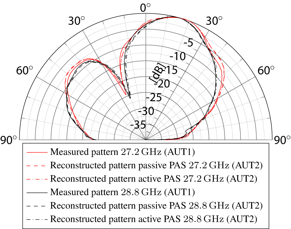
Cut of the measured and reconstructed FF beam pattern B.
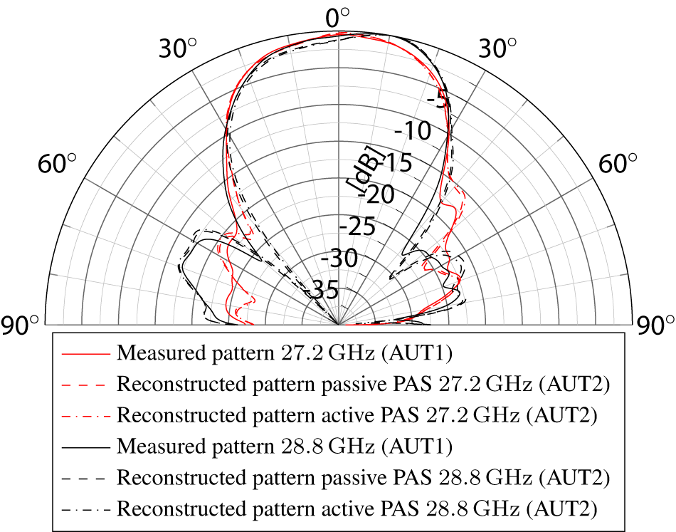
The second ESA (AUT2) was exclusively characterized in the NF setup by the active and passive PAS. The measured beam patterns A and B have also been captured in the same FF measurement setup as the single element patterns of AUT1. The second ESA (AUT2) is only configured and measured for the two BFN settings wA and wB. The measured vectors pa and pb are then multiplied with the reconstruction matrix R to get the complex scaling factors sA and sB. We use a separate reconstruction matrix for 27.2 GHz and 28.8 GHz. Using Equation (10) and the single element patterns of the reference ESA (AUT1), we are able to perform the beam reconstructions using Equation (11). Since it is only required to measure the four IF signals of the active PAS to achieve this, we can verify each BFN setting of the AUT in just a few seconds. The reconstruction performance shown in Figures 10 and 11 demonstrates how effective and precise this measurement approach is. The deviation to the measured FF beam pattern is below 1 dB. The reconstruction accuracy of the active PAS is on par with the passive PAS, but it has a much higher stability and repeatability over multiple measurements. The NF to FF correlation is valid over multiple days. Should the system have drifted too much, we can repeat the NF-calibration measurements with the golden AUT and calculate a new reconstruction matrix R, to continue the ESA verification.
Conclusion
The presented active PAS system is able to accurately reconstruct FF beam patterns of ESAs based on NF measurements and the NF to FF transformation. The NF measurement and reconstructions of the FF are very precise, fast, and repeatable. It is a major advantage compared to traditional antenna measurement systems, being able to perform broadband characterization without mmWave test equipment in such a compact setup. The frequency conversion of the active PAS also reduces the influences of phase drift and allows it to maintain the calibration state for a much longer period than the passive PAS. The exceptionally short measurement time of complete beams makes this system an ideal candidate for high-throughput testing applications in production environments. Furthermore, the active PAS is able to achieve a very high dynamic range compared to state-of-art antenna measurement system, due to the drastically reduced free space attenuation inherent to other OTA antenna measurements [Reference Walkenhorst4]. We have also shown that it is possible to characterize AUTs, which show leakage due to their BFN design. In future works, we will explore other methods to compensate leakage effects and show the potential to use the active PAS to create stimuli at its probes for an AUT. This would enable the active PAS to also evaluate AUTs in receive mode and reconstruct their corresponding receive patterns. For this, the algorithm described in Section 2 has to be altered at multiple steps.
Acknowledgements
We would like to thank NI for the provisioning of the Scarif ESAs and the corresponding control hardware. Their continued contributions to the design and construction of the active PAS were extremely valuable.
Competing interests
The authors report no competing interests.

M. Obermaier received his M.Sc. in Electrical Engineering from the Karlsruhe Institute of Technology in 2019. He currently works at the chair for RF and Photonics Engineering of the Technical University of Dresden. His main research interests are antenna and microwave measurement techniques.

T. Deckert is a Principal Engineer with NI where he is currently leading research in over-the-air measurement methodology. Prior to that he held various positions in development and product marketing for solutions to testing RF integrated circuits, wireless devices, and base stations. Thomas holds a Ph.D. degree in Wireless Communications, received from Technische Universität Dresden in 2007, and a M.Sc. degree in Electrical Engineering, received from the University of Wisconsin – Madison in 2002.

M. Laabs received the Dipl.-Ing. degree in Electrical Engineering from TU Dresden in 2011. He currently leads the RF systems group at the Chair for RF and Photonics Engineering at the Faculty of Electrical and Computer Engineering of TU Dresden. His research interest is focused on analog RF circuit and MMIC as well as RF system design for millimeter wave and THz systems. This includes space-borne hardware design for radar and communication systems.

D. Plettemeier (Member, IEEE) received the Ph.D. degree in Electrical Engineering from Ruhr-Universität Bochum, Bochum, Germany. Since 2011, he has been a Full Professor with the Chair of Radio Frequency and Photonics Engineering, Technische Universität Dresden, Dresden, Germany. He has been involved in several international scientific activities, as a Co-Investigator for ESA and NASA Space Missions, such as Cassini-Huygens, Rosetta, and ExoMars, mainly focusing on subsurface imaging. He is currently with the Centre for Tactile, Human-in-the-Loop and 6G-Life Research Hub, where he is involved in electronics for next generation sensor and communication systems. His research interests include millimeter-wave and terahertz systems, antennas and chip-integrated applications, microwave photonics, wave propagation, remote sensing, and imaging solutions for radar applications.


 Open access