


Introduction
The exponentially increasing wireless data demands have called for millimeter-wave frequency bands where the 60 GHz unlicensed band has especially attracted the researchers’ and industry's attention to realize several Gbps throughput. Higher atmospheric losses and oxygen absorption at 60 GHz ask for high-gain antennas which can be addressed by using dielectric lenses. Moreover, beam-steering can be employed to extend the coverage area of these high-gain narrow beam antennas. The feed-switchable antenna arrays feeding the lens have been largely reported in the literature [Reference Artemenko, Maltsev, Mozharovskiy, Sevastyanov, Ssorin and Maslennikov1–Reference Filipovic, Gauthier, Raman and Rebeiz5], however, the beam can only be steered to the predefined angles with this technique, and the link can break if the orientation of the antenna changes from its predefined position. This is true especially if we talk about the narrow-beam backhaul communications. This paper instead proposes a linear-phased antenna array to feed a dielectric lens antenna, where the feed will not only have significantly higher gain compared to single element used in feed-switching, but will also allow to steer the beam to any arbitrary angle in ± 45°. Moreover, excitation of 16-paths at the same time results in spatial power combining and will increase the effective isotropicradiated power (EIRP) by 12 dB compared to single-element excitation, as doubling the number of excitations results in 3 dB rise.
The idea of self-complementary ultra-wide band antenna arrays goes back to the 70s [Reference Inagaki, Isogai and Mushiake6], however, the concept of a periodically fed long slot was presented in [Reference Lee and Livingston7]. The further analysis of such an array was carried out in [Reference Neto and Lee8, Reference Neto and Lee9] with Green's function derivations. In this paper, the same idea of connected slots is used to design a broadband linear connected slots antenna array (CSAA) at 60 GHz. The mutual coupling in this coherent-phased array is used as an advantage to increase the impedance bandwidth [Reference Syed, Neto, Cavallo and van Zeijl10]. Moreover, this linear-phased array is fed periodically along its axis which allows to steer the beam in the azimuth plane (H-plane). The CSAA is used as a feed for the high-gain dielectric lens, bringing advantages of connected slots and lens antenna together in one place, resulting in a broadband and beam-steerable design. Keeping in view the applications where communication nodes are in the same plane, e.g. wireless mesh network, track-to-train, etc., the dielectric lens is designed to provide a fixed narrow-beam in the elevation plane while CSAA steers the beam in the azimuth plane for broad coverage. The beam-steering capabilities of the design are tested using four different power splitters that allow the beam to steer at 0, 15, 30, and 45°. The 3 dB beam-steering range is at least ± 45° as higher angles are not tested. The proposed solution is planned to be integrated with 16-path RFIC [Reference Ojefors, Andreasson, Kjellberg, Aspemyr, Nilsson, Brink, Dahlb, Wu and Sj11] that can steer the beam at any arbitrary angle in the beam-steering range. Besides, this paper is an extension of the research presented in [Reference Aziz, Öjefors, Dahlbäck, Rydberg, Engblom and Dancila12].
Connected slots array design
The design of the CSAA presented in this paper is based upon the unit cell shown in Fig. 1(a). The inset shows the zoom-in view of the slot, which is narrowed in the center to lower the localized reactive energy and improve the impedance bandwidth. Two faces of the linear array are assigned as master/slave pair in Ansys HFSS to create the infinite periodic boundaries. A single layer low loss PCB material Astra MT77 (εr = 3 and tanδ = 0.0017) is used to design the connected slots array. As shown in Fig. 1(b), the slot plane is fed from other side of the PCB with the help of a microstrip line by a via pin.
CSAA feeding a dielectric lens (a) unit cell with infinite periodic boundaries. (b) Elevation plane (E-plane) view of simulation setup.
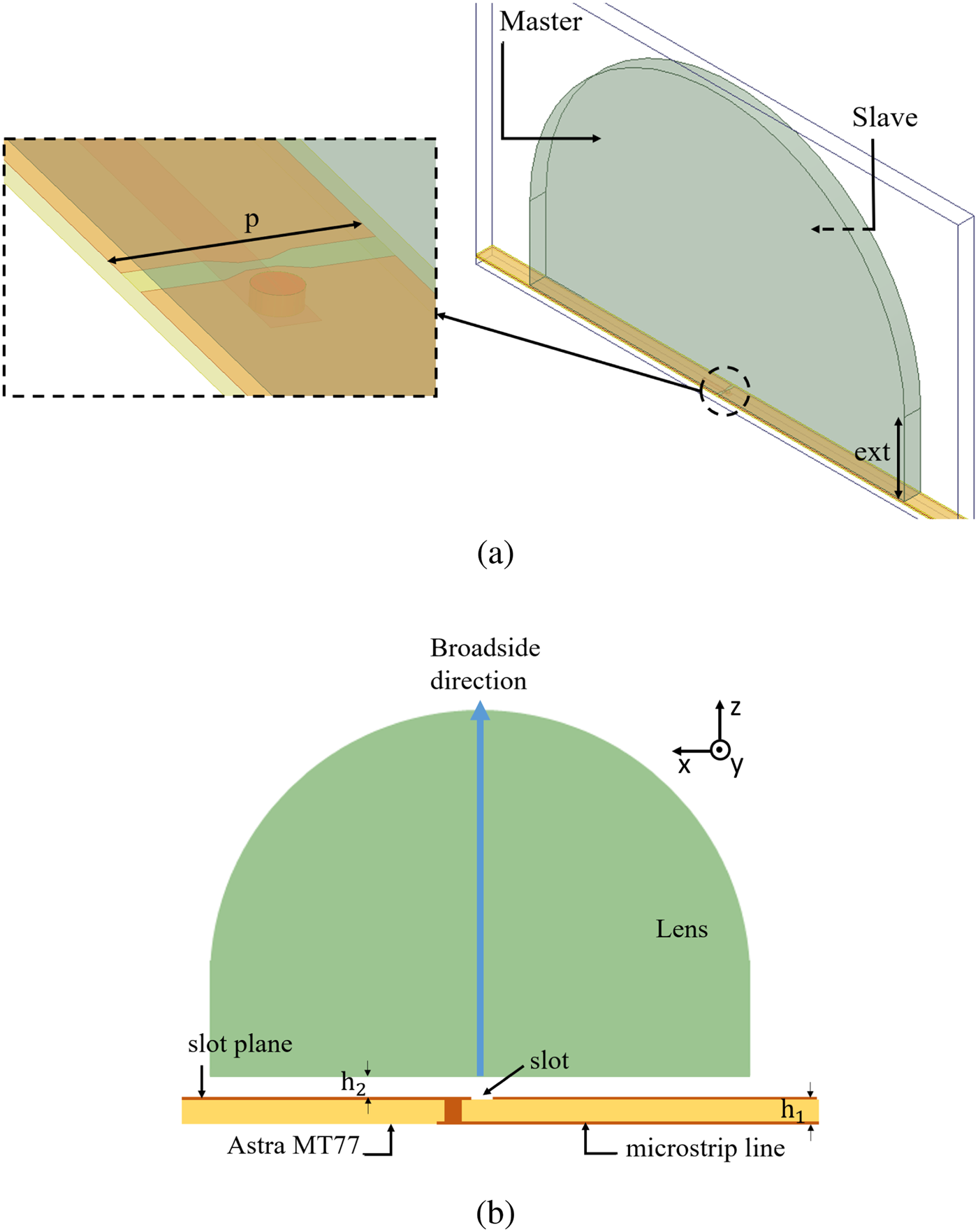
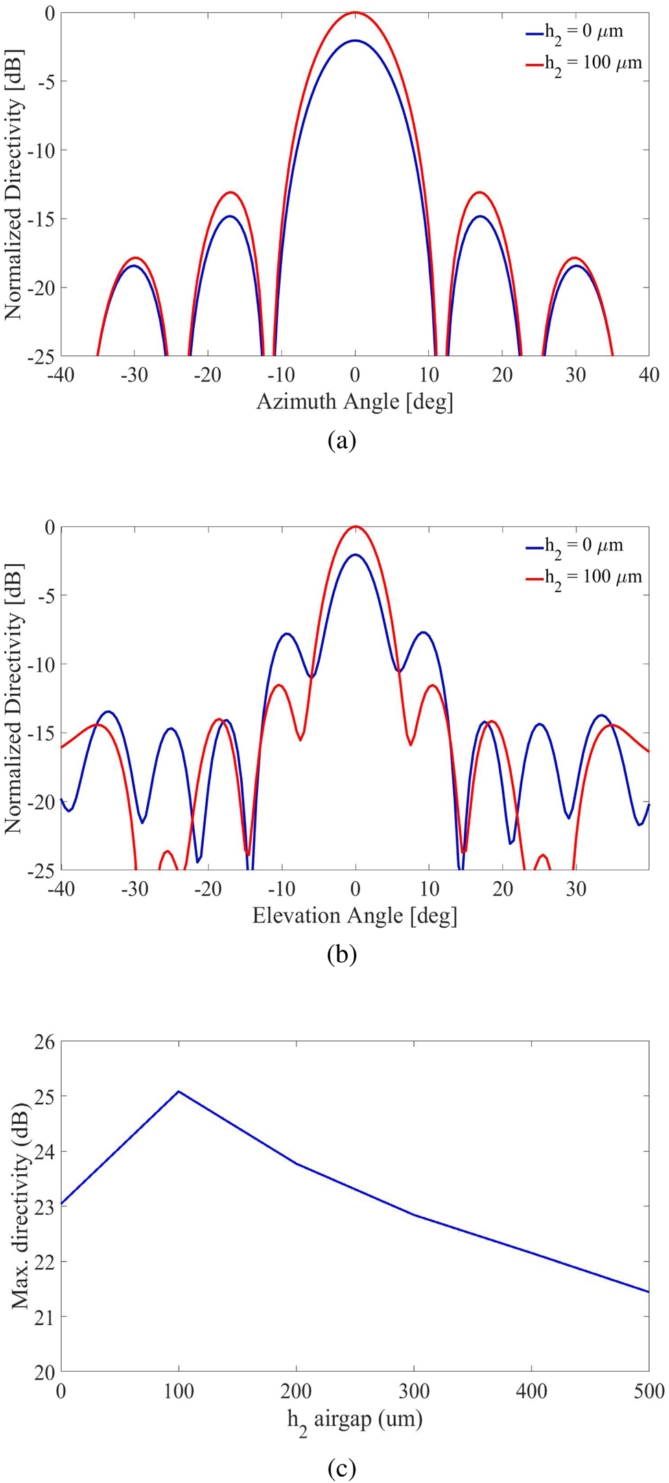
As the propagation constant for a slot is $\beta = \sqrt {( k_1^2 + k_2^2) /2}$ , where k 1 and k 2 are propagation constants of two medium separated by the slot plane, the leaky wave angle cos −1(β/k 2) is only 45° for maximum contrast between εr values of the two medium, thus giving 90° beam separation [Reference Neto13]. To reduce this beam separation, i.e. focus more power in the broadside direction, leaky wave angle can be increased by modifying the structure in a way that propagation constant β ≈ k 1, where k 1 corresponds to lesser dense medium. This can either be done by adding a low εr superstrate layer between the slot plane and dense dielectric lens [Reference Llombart, Chattopadhyay, Skalare and Mehdi14] or by introducing a small airgap [Reference Neto13], which is a cost effective and easy to realize alternative to superstrate. Figure 2(a) shows that this airgap (h 2) acts as a guiding structure resulting in a directivity improvement of more than 2 dB. Besides, among other modes, a cylindrical expanding TM wave is excited by the slot which spreads homogeneously above the slot when there is a free space above it. However, if we look at the elevation plane (E-plane view, Fig. 1(b)) for better understanding, the waves bend away from the broadside when high εr lens is in direct contact with the slot plane. These waves illuminate the lens areas away from the center, and thus giving rise to side lobe levels (SLLs). This is explained in the elevation plane radiation pattern shown in Fig. 2(b), where the SLLs are much higher when no airgap is placed between the slot plane and dielectric lens (i.e. h 2 = 0) compared to when h 2 = 100 μm. A more detailed comparison of maximum directivity as a function of h 2 is shown in panel (c) of the figure. It can be seen that maximum value of 25.1 dB is achieved when airgap is 100 μm and it reduces with increase of this h 2 value. This gap can be realized by placing a 100 μm thick shim between the PCB and lens. Besides, the slot is placed at the center of the lens which gives broadside beam in the elevation plane. If the slot/lens is offset from the center, the beam is steered few degrees away from the broadside, i.e. an offset of 200 μm results in 1.5° beam offset from the broadside without affecting the realized gain, SLL, and impedance matching. Moreover, Fig. 3(a) shows the active reflection coefficient comparison for different values of the airgap between the slot plane and lens. Less than − 10 dB impedance bandwidth is more than 33% when h 2 = 100 μm. The impedance is reactive when there is no airgap (h 2 = 0) and moves toward lower impedance for values higher than 100 μm.
Directivity as a function of airgap: (a) normalized directivity at 61.5 GHz when CSAA feeding a lens antenna with and without a small airgap “h 2” between slot plane and lens, azimuth (H-plane) view, (b) elevation (E-plane) view with and without the airgap, and (c) maximum directivity as a function of “h 2” airgap.
Parametric study (all units are in mm): (a) simulated S 11 for different heights of h 2 airgap and (b) simulated S 11 for different values of pitch p between adjacent feed points.

As it is obvious from the name of connected slots that there is no discontinuity between individual slots, thus the mutual coupling is very high between each element, which is however used to increase the impedance bandwidth in this coherent phase array. The pitch “p” between the feed points is optimized and observed that impedance is more reactive when the pitch is closer to half wavelength, which becomes more real toward the quarter wavelength. Reflection coefficient for different values of the pitch are shown in Fig. 3(b). Besides, the radiation patterns for different values of the pitch are similar to comparable gains, so a value closer to quarter wavelength is used that provides impedance matching from 55 to 75 GHz. This also makes CSAA significantly compact compared to if pitch is half wavelength.
Power splitters
A 50 Ω coaxial based RPC-1.85 Rosenberger connectorFootnote 1 is used as a launching pad for the RF signal. As shown in Fig. 4, the pad is shorted with the slot plane with the help of PCB VIAs. The signal pin in the connector connects with the 50 Ω microstrip line while 50–70.7–100 Ω impedance transformation is used in designing the 1:16 splitter networks. For power splitter shown in Fig. 4(a), lengths of all 16 paths is the same, i.e. all feed points on the CSAA are fed with the same phase, thus giving rise to the broadside beam. However, for Fig. 4(b), 4(c), and 4(d), the lengths of the lines increase gradually when moving from left to right on the CSAA no y-axis, which results in progressive phase delay. This progressive phase delay steers the beam away from the broadside in the elevation plane (H-plane). More is the phase delay, higher is the beam-steering angle. Figures 4(b), 4(c), and 4(d) present the power splitters designed to steer the beam at 15, 30, and 45°, respectively. These splitters are being used only for characterization of the array, as the plan is to integrate this array with 16-path RFIC [Reference Ojefors, Andreasson, Kjellberg, Aspemyr, Nilsson, Brink, Dahlb, Wu and Sj11].
Power splitters to steer the beam at (a) 0° with the inset showing the connected slots on other side of the PCB: (b) 15°, (c) 30°, and (d) 45°.

Lens design
The higher dielectric constant values of lens material provide better power coupling into the lens body from the feed [Reference Sauleau, Fernandes and Costa15], so a high dielectric constant low loss material Preperm PPE950 Footnote 2 (εr = 9.5 and tan δ = 0.0025) is used as the lens. As the eccentricity e of an ellipse is inversely proportional to the dielectric constant of the material, $e = 1/\sqrt \epsilon _r$ , an elliptical lens can be well approximated as extended hemispherical lens for high dielectric constant values [Reference Filpovic16]. In other words, the extension height will be higher for lower εr values, which causes more power to be spill over, i.e. fields leaking out from the extension part of lens [Reference Karttunen, Ala-Laurinaho, Sauleau and Räisänen17]. This extension ext in the Z-direction is calculated and optimized to have the feed at the lower focus of the lens, which provides a plane wave above the lens. Figure 5 shows the maximum directivity as a function of ext and it can be seen that the value is maximum (25.1 dB) when 7 mm extension length is used.
Simulated maximum directivity as a function of lens extension length (ext).

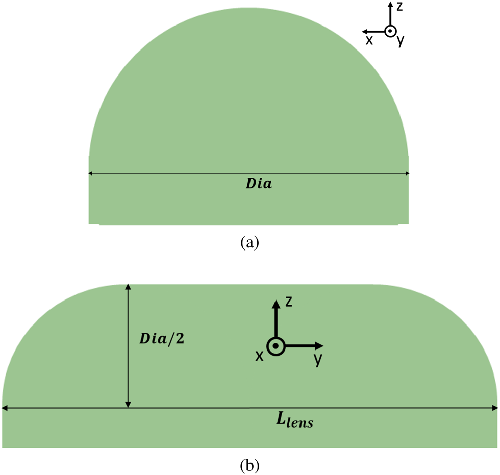
The 24 mm long CSAA, shown in Fig. 4(a), is used as feed for the lens. Figure 6(a) shows the elevation view of the lens antenna. As the CSAA is extended along YY′, this feed can be viewed as a point source in this plane. It is mainly this plane where the lens plays its major role to increase the gain and reduce beam width. This is evident from the elevation plane radiation pattern in Fig. 2(b) as the half power beamwidth (HPBW) is 6° in this plane. Besides, keeping in view the length of the feed extended along YY′, rotationally symmetric hemispherical lens cannot be used in this case. Instead a half cylindrical lens with hemispheric terminations is employed as shown in the azimuth plane view in Fig. 6(b). When all 16 feed points in the CSAA are excited in phase (0° beam), it is mainly the array itself which results in 10° HPBW is the azimuth plane and the lens doesn't contribute in it. However, when the CSAA is excited in a way to steer the beam away from the broadside in this azimuth plane, the hemispherical terminations play their role to enhance the gain. For usual phased arrays, the gain reduces with higher beam-steering angles because of angular dependence of element radiation pattern, called scan loss [Reference Lamminen18]. However, in our case, the gain increases up to certain beam-steering angles because of hemispherical terminations, which is further discussed with the measurement results in next section.
Design view of dielectric lens: (a) elevation plane (XZ) view and (b) azimuth plane (YZ) view of the lens antenna, the CSAA extend along the Y-axis.
The design dimensions for the feed and the lens are tabulated in Table 1.
Design dimensions for CSAA feeding the dielectric lens

Fabrication and measurements
The microstrip-fed CSAA is fabricated on a single layer Astra PCB with four different power splitters (1:16) to measure the beam-steered radiation patterns at 0, 15, 30, and 45°. The PCB with the power splitter for 0° beam excites all 16-feed points with the same phase and amplitude, while below relation is used to calculate the progressive phase increment between adjacent columns to achieve the beam steering at any angle θ:

where β = 2π/λo and p is the distance between two adjacent feed points.
The dielectric lens antenna is fabricated from a block of Preprem PPE950 to the shape shown Fig. 7(a) by milling machine. The base of the lens is made rectangular (in xx′) with some thickness to mechanically support the Rosenberger connector. This rectangular base, which is extended beyond the circular base, does not affect the performance of the lens as rays impinging below the “ext” height do not get focused by the lens. These rays will be scattered in pointless directions even if the lens is shaped as shown in Fig. 6.
Fabricated structures: (a) lens and (b) PCB screwed with the lens.
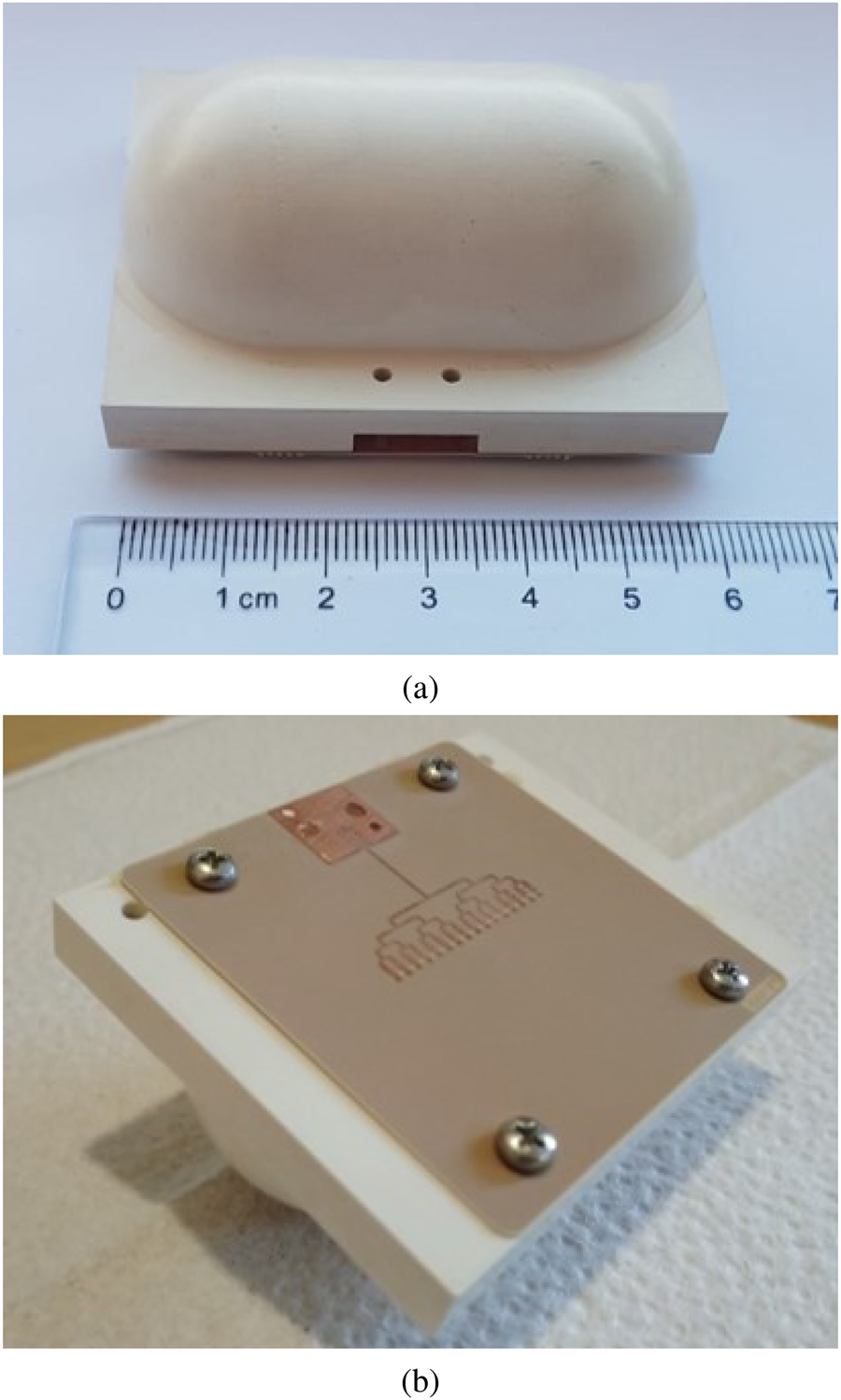
Figure 7(b) shows the CSAA fed through 1:16 power splitter to achieve the main beam at broadside (0°). A coax-based Rosenberger connector is used to feed the signal from network analyzer. The reflection coefficient measurements are presented in Fig. 8 when different power splitters are in place to steer the main beam. All the arrays almost cover the 60 GHz license free band 57–66 GHz. The − 10 dB impedance bandwidth is 10 GHz (55–65 GHz), 12 GHz (55–67 GHz), 12 GHz (55–67 GHz), and 10 GHz (55–65 GHz) for 0, 15, 30, and 45° beam-steering arrays, respectively.
Measured S 11 when different power splitters are in place to steer the beam at different angles.

The radiation patterns of this CSAA-fed lens antenna is measured with the help of standard horn antennas at 2° steps. Figures 9(a) and 9(b) show the elevation plane (E-plane) and azimuth plane (H-plane) normalized radiation patterns centered at 0° for different frequencies from 56 to 70 GHz. The dashed line at 60 GHz presents the simulation results obtained by using the symmetry boundary as full structure simulation is not possible due to RAM limitations. The simulations agree very well in the azimuth plane but in the elevation plane there are higher side lobes at ± 35°, which might be a shift of lobes as some higher lobes are also present in the measurements at ± 50°. The HPBW in the elevation and azimuth planes is around 6 and 10°, respectively, which nicely agrees with the simulation results. Moreover, looking at the elevation plane view, all the beams are centered at 0° with SLL less than 10 dB, which can be further improved by power tapering to the edge elements. Figures 10(a), 10(b), and 10(c) present the beam-steered radiation patterns in the azimuth plane for 15°, 30° and 45°. The beams are centered around given angles with couple of degrees stretch. Comparatively higher side lobes being observed in Fig. 10(a) for 62 and 64 GHz seem to be due to some localized effect of the PCB as side lobes are much lower even for high steering angles.
Measured normalized radiation patterns when beam is pointed at broadside, the dashed curve at 60 GHz present the simulation results: (a) elevation plane (E-plane) and (b) azimuth plane (H-plane).

Azimuth plane measured normalized radiation patterns: (a) beam steered at 15°, (b) beam steered at 30°, and (c) beam steered at 45°.

Figure 11 shows the gain over the band 55–70 GHz. Gain is measured with the help of comparison method, where S 21 is measured for two standard horn antennas and then one of them is replaced with the test antenna. The measurement results at 0° fairly agree to the simulation curve where the measured values range between 22.8 and 24.4 dBi in 57–66 GHz bandwidth. No comparison of measurements and simulations is shown for other beam-steering angles as master/slave or symmetry boundary conditions are used in the simulations which either do not take into consideration the hemi-spherical terminations on the YY′ axis or doesn't allow beam-steering (as symmetry boundary condition doesn't provide option for progressive phase shift on other side of the boundary). These hemi-spherical terminations play a role in improving the gain of the array when beam is steered away from the broadside. The slight increment in the gain can be observed in the 15° curve where gain values lie between 23.5 and 24.5 dBi in the 57–66 GHz band. This increment is more obvious for 30° curve which has the highest measured gain over the entire band. The gain values lie between 24.3 and 25.4 dBi in the band of interest. The effect of hemi-spherical terminations on the gain is observed to relatively reduce for 45° where gain varies between 22.6 and 24.1 dBi in 57–66 GHz band. The gain is slightly higher at lower end of the band than the upper, which might be because of better impedance matching in the lower band, nonetheless, gain is in 1 dB range from the 0° beam. The 3 dB gain bandwidth of the CSAA-fed lens covers the entire 60 GHz band for all beam-steering angles. Moreover, the 3 dB beam-steering range for the presented antenna array is at least ± 45° as higher beam-steering angles are not measured.
Measured gain for all different beam angles along with simulated gain for 0° beam.

The results presented in this paper are limited to 0, 15, 30, and 45° as only four different power splitters are fabricated to characterize the performance of the array. However, this array shall be integrated with the 16-path 57–71 GHz beam-forming Si–Ge transceiver chip [Reference Ojefors, Andreasson, Kjellberg, Aspemyr, Nilsson, Brink, Dahlb, Wu and Sj11] which can excite each feed point of CSAA with appropriate phase and amplitude to steer the beam at any arbitrary angle in ± 45° and beyond.
Conclusion
This paper presents an antenna design having 25.4 dBi maximum gain and 3 dB gain bandwidth covering the entire 60 GHz band. The beam-steering range (3 dB) is at least ± 45° while the hemispherical terminations on the azimuth plane play a role in improving the gain when beam is steered away from broadside. Table 2 provides a performance comparison with similar research reported in the literature, where every solution summarized in the table utilizes feed switching to achieve the beam-steering except [Reference Costa, Lima and Fernandes19] which mechanically steers the lens above a horn feed. To our knowledge, this is the first solution which integrates the phased array with the dielectric lens to achieve the beam-steering. The 16-feed point CSAA enables to steer the beam at any arbitrary angle in ± 45° or beyond with the help of 16-path RFIC. The performance of the presented solution makes it a good candidate for high data rate 60 GHz backhaul and access communications.
Comparison with the similar reported study

Acknowledgments
This study has been funded by the Swedish agency, Vinnova for 60 GHz RF beam-steering solution with phased array antenna for Small Cell backhaul and wireless access points (Project No. 2016-01800). We are thankful to the Nataly Tamir and Ebrahim Bagheri for their help in PCB manufacturing and measurements, respectively. We are also thankful to Mirpur University of Science & Technology (MUST), Mirpur, Pakistan, for financial support of Imran Aziz.
 Imran Aziz received his B.Sc. and M.Sc. degrees in Electrical Engineering from the University of Azad Jammu and Kashmir, Muzaffarabad, Pakistan in 2007 and 2013, respectively. Between 2007 and 2012, he worked in Special Communications Organization (SCO) as Communication Engineer and in Huawei Technologies as GSM BSS Engineer. In 2012, he joined the Mirpur University of Science and Technology (MUST), Mirpur Azad Jammu and Kashmir, Pakistan, as a Lecturer in the Department of Electrical Engineering. He started his Ph.D. in 2016 at Uppsala University, Sweden and his research interests include antenna arrays design, fabrication and measurements, millimeter and sub-millimeter wave communications, beam steering and phased array antennas for different applications from broadband 5G to high data rate high energy physics. During his Ph.D., he has remained involved in different projects at 60 GHz and 28 GHz antennas in package and the outcome of those projects have found their place in the commercial market. He is also working on development of 60 GHz wireless interfaces for different harsh environment applications ranging from cryogenics to data read-out in irradiation environment at ATLAS, CERN.
 Erik Öjefors (S’01–M’06) received his M.Sc. degree in Engineering Physics and his Ph.D. degree in Microwave Technology from Uppsala University, Sweden, in 2000 and 2006 respectively. In 2007 he joined the Institute of High-Frequency and Quantum Electronics at the University of Siegen, Germany. Between 2008 and 2011, he was with the Institute for High-frequency and Communication Technology at the University of Wuppertal, Germany. Since 2011, he is a Senior RF Engineer with Sivers IMA AB, Kista, Sweden. He was the co-recipient of the 2007 IEEE AP-S R. W. P. King Award, the 2008 EuMIC Best Paper Award, and the 2010 EuMC Microwave Prize.
 Dragos Dancila graduated in Electrical Engineering (magna cum laude) from Universite catholique de Louvain (UCL), Louvain-la-Neuve, Belgium, in 2006. He received Ph.D. in Applied Sciences with specialization in Microwave Engineering from UCL. He is recipient of the prestigious FRIA grant of the National Science Foundation (FNRS), Belgium. The Ph.D. studies were performed at IMEC, Belgium. He also received a complementary Master in Business Management, from the Solvay Business School, Brussels. He worked at Ecole Polytechnique (UCL) as postdoctoral researcher in the field of RF power breakdown for space applications. Since 2011, he is working as senior researcher at Solid State Electronics Division, Uppsala University. During the period 2012–2015 he was project leader for Uppsala University in the EU projects NANOTEC and NANOCOM. In 2015 he worked as a senior research engineer at Ascilion AB, developing a non-invasive blood glucose sensor. In April 2018, he was appointed Docent (Associate Professor) in Microwave Engineering at Uppsala University. He is the Swedish Principal Investigator of the Eurostars project ENEFRF - Energy Efficient PET Cancer Diagnostics: Novel RF Source for Radioisotope Production. He is also part of the SSF project: MEMS terahertz systems and leads the work in several national projects on non-invasive sensing, such as skin cancer detection and glucose monitoring. He is leading the research group on RF solid-state power amplifiers at Solid State Electronics and FREIA Divisions, Uppsala University. He is author or co-author of more than 80 publications including journals and conferences. He received the best measurement paper award, EUCAP 2013. He has translated two reference books into French in the field of microelectronics (Fundamentals of Electric Circuits and Microelectronic Circuits) and is teaching the analog electronics course to a class of hundred. He is reviewer for several journals and since 2018, Deputy Section Editor of IET's The Journal of Engineering. His current research interests are in the areas of solid-state RF power amplifiers, 60 GHz communications, millimeterwave and terahertz technology, adaptive and integrated antennas, RF-MEMS, and non-invasive medical sensors.


 Open access