


1 Introduction
High-power short-pulse lasers open new horizons in laser–plasma physics. In addition to being routinely used for particle acceleration[ Reference Macchi, Borghesi and Passoni1– Reference Tajima, Yan and Ebisuzaki4], they have also been deemed to be a plausible path to fusion[ Reference Danson, Hillier, Hopps and Neely5, Reference Ruhl and Korn6]. This class of laser facilities utilizes beamlines with fixed F-number of the final focusing optic, which usually represents an off-axis parabolic mirror or a spherical mirror for producing an aberration-free, diffraction-limited focus. Such optics have high fabrication costs associated with their specialized optical characteristics (such as surface roughness, surface figure, coating uniformity, surface and coating defects) across a large (meter-class) clear aperture. Extending the tunable range of intensity at the laser focus broadens the range of intensity-dependent phenomena that can be investigated at the same beamline. For a beamline with a fixed F-number, the intensity achievable at the laser focus can be primarily adjusted by controlling the pulse duration and pulse energy. However, temporally stretching the pulse or reducing the energy results in lower intensities at the focus and might be detrimental for the process under investigation.
Alternatively, an adjustable intensity at the laser focal plane can be achieved by changing the F-number of the beam after the final focusing optic while keeping the pulse duration and energy constant. Traditionally, this approach relies on curved plasma mirrors (PMs) – transparent optics that are inserted in the vicinity of the final focus, where the laser at high fluence ignites a reflective plasma sheath on the optics’ surface[ Reference Murnane, Kapteyn and Falcone7]. As first shown by Gold et al. [ Reference Gold, Nathel, Bolton, White and Van Woerkom8] on flat substrates, the plasma reflectivity can be high, while the spatial profile of the reflected beam is smooth. Moreover, the generated plasma acts as a self-induced temporal shutter[ Reference Kapteyn, Murnane, Szoke and Falcone9], leading to numerous applications of PMs for temporal contrast improvement of the laser pulse[ Reference Ziener, Foster, Divall, Hooker, Hutchinson, Langley and Neely10– Reference Choi, Jeon, Lee, Kim, Kim, Kim, Lee, Yoon, Sung, Lee and Nam24]. Temporal contrast is recognized as a critical parameter for efficient laser interaction with nanometer-thick solid targets, as for example demonstrated in Ref. [Reference Dover, Ziegler, Assenbaum, Bernert, Bock, Brack, Cowan, Ditter, Garten, Gaus, Goethel, Hicks, Kiriyama, Kluge, Koga, Kon, Kondo, Kraft, Kroll, Lowe, Metzkes-Ng, Miyatake, Najmudin, Püschel, Rehwald, Reimold, Sakaki, Schlenvoigt, Shiokawa, Umlandt, Schramm, Zeil and Nishiuchi25].
The application of curved PM substrates to refocus the laser beam to a smaller F-number was initially proposed by Nakatsutsumi et al. [ Reference Nakatsutsumi, Kon, Buffechoux, Audebert, Fuchs and Kodama26], where an ellipsoidal PM made of glass with an antireflective surface coating was used to reach higher intensities[ Reference Nakatsutsumi, Sentoku, Korzhimanov, Chen, Buffechoux, Kon, Atherton, Audebert, Geissel, Hurd, Kimmel, Rambo, Schollmeier, Schwarz, Starodubtsev, Gremillet, Kodama and Fuchs27]. However, glass ellipsoidal mirrors are difficult to polish due to the complex surface geometry preventing scalability of mass production and making them expensive. Wilson et al. [ Reference Wilson, King, Gray, Carroll, Dance, Butler, Armstrong, Hawkes, Clarke, Robertson, Bourgenot, Neely and McKenna28] advanced this method by implementing an approach of producing plastic ellipsoidal PMs by casting a plastic ellipsoid from a computer numerical control (CNC) machined metal mold. Yet, the plastic mirrors are impaired by reduced surface quality after the casting process. Another example of curved optics is the use of a single spherical PM by Kojima et al. [ Reference Kojima, Abe, Miura, Ozaki, Yamanoi, Ikeda, Wang, Dun, Guo, Maekawa, Takizawa, Morita, Asano, Arikawa, Sawada, Ishii, Hanayama, Okihara, Kitagawa, Kajimura, Morace, Shiraga, Shigemori, Sunahara, Iwata, Sano, Sentoku, Johzaki, Nishikino, Iwamoto, Nagaoka, Sakagami, Fujioka and Mori29] to refocus the laser beam in the target chamber, although to avoid introducing aberrations the F-number of the beam needs to be constant and the angle of incidence on the mirror is limited to the range of 0°–0.5°. A theoretical study using an off-axis parabolic PM to change the F-number of a tightly focused beam was recently published by Geng et al.[ Reference Geng, Xu, Zhang, Kostyukov, Pukhov, Shen and Ji30] in the context of laser-electron acceleration. All these examples utilize optics with tight curvatures (focal length of ~3 mm in Ref. [Reference Nakatsutsumi, Sentoku, Korzhimanov, Chen, Buffechoux, Kon, Atherton, Audebert, Geissel, Hurd, Kimmel, Rambo, Schollmeier, Schwarz, Starodubtsev, Gremillet, Kodama and Fuchs27] and <1 mm in Ref. [Reference Geng, Xu, Zhang, Kostyukov, Pukhov, Shen and Ji30]), which poses unique challenges to the design and application of the antireflective coating across the surface due to the large range of incidence angles and broad bandwidth of short-pulse laser beams. This limitation further constrains the broader use of curved PM optics for F-number adjustments. To overcome the limitations mentioned above, we consider optical systems in which the beam is reflected between two or more curved optical elements without being obscured by the reflecting optics, referred to as ‘unobscured optical systems’. Outside the field of high-power lasers, imaging with unobscured optical systems consisting of two spherical mirrors has been largely implemented in telescopic instrumentation, where near diffraction-limited image quality has been achieved. Optimal configurations for the spherical mirrors can be chosen based on second-order aberration theory[ Reference Howard and Stone31]. As one particular example, Kutter[ Reference Kutter32] developed the Schiefspiegler telescope having an unobscured optical configuration with two spherical mirrors, while Buchroeder and Leonard[ Reference Buchroeder and Leonard33] further implemented aspheric modifications in Yolo telescopes that allowed for a better correction of the astigmatism.
Here, we build on the approach of using two spherical glass substrates to design and implement a double-plasma-mirror (DPM) telescope for both adjusting the F-number, and hence the intensity at focus, and enhancing the temporal contrast of a large-aperture, multi-petawatt (PW) laser system. The configuration of the mirrors is chosen such that the aberrations from the two surfaces are nearly cancelled out, allowing for a rather large angle of incidence on the spherical mirrors while the distribution of incidence angles across the beam aperture stays narrow to effectively utilize the antireflective coating for contrast enhancement. Furthermore, the system’s design ensures low sensitivity to misalignment, allowing for intensity adjustment simply by changing the distances in the optical system, unlike systems that rely on higher-order optical surfaces.
A custom-designed, high-power imaging diagnostic was implemented to validate the spatial energy distribution and peak intensity at the laser pulse focus, with a total energy of 188 J in 24 fs duration (7.8 PW) delivered to the target chamber, and to evaluate the total reflectivity of the DPM system at such high energies. In addition, enhancement of the temporal intensity contrast of the multi-PW laser beam is confirmed by the higher particle yield and increased cut-off kinetic energy of laser-driven proton beams from nanometer-thick flat foils, compared to a system without contrast-enhancing PMs.
2 Double-plasma-mirror setup and high-power diagnostic
2.1 Configuration of the double-plasma-mirror system
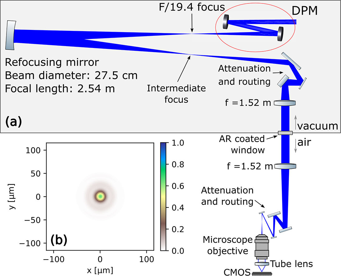
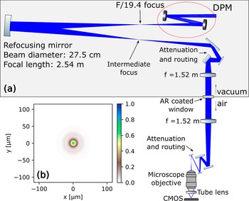
The spherical DPM system was implemented at the 10 PW long-focus beamline at the Extreme Light Infrastructure – Nuclear Physics (ELI-NP) facility. Linearly polarized laser pulses at 810 nm central wavelength, 24 ± 1 fs (full width at half maximum, FWHM) in duration, enclosing a total energy up to 188 J, with a beam diameter of 48 cm, are primarily focused by an F/63.5 on-axis spherical mirror with a focal length of 30.5 m[ Reference Radier, Chalus, Charbonneau, Thambirajah, Deschamps, David, Barbe, Etter, Matras, Ricaud, Leroux, Richard, Lureau, Baleanu, Banici, Gradinariu, Caldararu, Capiteanu, Naziru, Diaconescu, Iancu, Dabu, Ursescu, Dancus, Ur, Tanaka and Zamfir34]. The focused beam subsequently passes through a central hole in the final turning mirror, located before the focusing spherical mirror, to reach the target chamber (Figure 1(a)). This results in an F/63.5 focal spot, depicted in Figure 1(b), as measured by an imaging system located downstream of the focal plane at 20 μJ pulse energy. The implemented DPM system is positioned near the focal plane of the F/63.5 focusing mirror, forming a telescope with a pair of spherical glass substrates resulting in an F/19.4 focus, as shown in Figure 1(a). In this configuration, the first mirror of the system, PM1, exhibits a convex front surface with a radius of curvature of 155 mm, while the second mirror, PM2, exhibits a concave front surface with a radius of curvature of 103.7 mm. PM1 is placed 178 mm upstream of the F/63.5 focal plane. PM1 and PM2 are separated by 43.5 mm and the angle of incidence is fixed at 7° on each PM. The resulting focal plane is located 73 mm from PM2, ensuring sufficient clearance for positioning of samples to be irradiated at the focus. Commercial off-the-shelf spherical lenses were selected for PM substrates due to their high optical quality and availability in large quantities. An antireflective coating (0.3% ± 0.05% reflectivity between 760 and 860 nm) is applied on both surfaces of the PMs to minimize the reflection of any preceding signal and potential pre-pulses prior to the main laser peak. The antireflective coating on the back surface facilitates additionally the alignment of the PMs in the presence of multiple reflections caused by the rear surfaces (see Section 3.1 of the supplementary information (SI)).
(a) Laser beam delivery and double-plasma-mirror (DPM) configuration implemented at ELI-NP. PM1, convex plasma mirror 1; PM2, concave plasma mirror 2. A deformable mirror, DM, located at the compressor enables fine adjustment of the focus. An F/63.5 spherical mirror, SM, focuses the laser through the routing hole in the last turning mirror into the target chamber. The F/63.5 laser beam is s-polarized on the plasma mirrors impinging at a 7° angle of incidence. The plasma-mirror substrates were anti-reflection (AR) coated on both front and back surfaces. (b) Experimental focus of the F/63.5 beam as measured in a downstream microscope (pulse energy is reduced to 20 μJ) (FWHM: 54.4 μm; EE: 25.7%). (c) Simulated focus of the resulting F/19.4 with deformable mirror correction (FWHM: 16.1 μm; EE: 44.6%) and (d) the corresponding experimental focus as measured in the downstream microscope (pulse energy is reduced to 20 μJ) (FWHM: 15.5±1.2 μm; EE: 22.9%±2%). FWHM, full width at half maximum of the focus; EE, encircled energy within FWHM. The inset in (c) shows horizontal and vertical lineouts of the simulated and experimental foci. See Section 4 of the SI for details on the focus image analysis and background treatment.

Likewise, the DPM system was positioned to ensure that the s-polarized beam[ Reference Nomura, Veisz, Schmid, Wittmann, Wild and Krausz35] has a diameter of 2.6 mm on the first mirror, leading to laser intensities in the range of 1016–1017 W/cm2 (Section 3.2 of the SI). Ziener et al. [ Reference Ziener, Foster, Divall, Hooker, Hutchinson, Langley and Neely10] and Kim et al. [ Reference Kim, Choi, Lee, Janulewicz, Sung, Yu, Kim, Yun, Jeong and Lee36] reported that exposure of PMs to excessively high intensities can lead to beam distortions that could be attributed to early expansion of the plasma triggered by pre-pulses. For the chosen 1016–1017 W/cm2 peak intensities and given the measured inherent temporal intensity contrast of the ELI-NP laser beam, less than 10–7 at –5 ps (see Ref. [Reference Chalus, Derycke, Charbonneau, Pasternak, Ricaud, Fischer, Scutelnic, Gaul, Korn, Norbaev, Popa, Vasescu, Toma, Cojocaru and Dancus37] and Figure S4 of the SI), the preceding signal lacks sufficient intensity to initiate plasma formation. As a result, this preceding signal passes through the mirrors of the DPM telescope system, enhancing the temporal intensity contrast in the process. The peak intensities are anticipated to yield maximum reflectivity, as indicated by PM reflectivity scan measurements conducted by Shaw et al. [ Reference Shaw, Steinke, van Tilborg and Leemans20] at the BELLA center with enhanced laser contrast. Our measurements, as discussed in the next section, confirm that the chosen intensity range yields optimum PM reflectivity.
Ray-tracing simulations using OpticStudio by Zemax (Ansys) provide an estimate of the aberrations for the DPM configuration described above (see Figures S5(a) and S5(b) in the SI). Simulations anticipate that the focus after the DPM system preserves the majority of the energy around the central region, as shown by a theoretical Strehl ratio reaching 0.776. The wings are an order of magnitude lower in intensity than the central peak and are dominated by vertical astigmatism, which can be corrected by the deformable mirror located upstream in the laser beamline. In addition, a moderate flexing of the deformable mirror membrane in the range of ±210 nm is sufficient to reduce this aberration (see Section 3.4 of the SI). The resulting simulated focus after deformable mirror correction is shown in Figure 1(c).
Experimentally, a microscope positioned downstream of the focal plane images the resulting focus at low energy (20 μJ) in the F/19.4 configuration. Figure 1(d) shows a representative image of the measured energy distribution at the focal plane under these conditions. The microscope is constructed with a 5× objective (Mitutoyo) and a tube lens with a resulting numerical aperture of 0.14, thereby inducing negligible aberrations to the measured focus. As anticipated, the DPM system introduced low-order residual astigmatism, which was effectively corrected using the deformable mirror as described in Section 3.4 of the SI. Those minimal aberrations in the measured F/19.4 focal spot are evident from the horizontal and vertical lineouts when compared to the simulated focal spot (inset in Figure 1(c)). Consequently, the experimentally measured focus exhibits a diameter of (15.5 ± 1.2) μm (FWHM), in line with the expected value from simulations, while ensuring an encircled energy of 22.9% ± 2%. The similarity of the encircled energy measured in the DPM F/19.4 focus with the original F/63.5 focus (25.7%) indicates that two factors may contribute to the reduction of the encircled energy compared to the ideal case (~50%): the presence of higher-order Zernike terms that could not be corrected with the deformable mirror, and the optical power spectral density of the spherical focusing mirror that contributes to the scattering of light in the vicinity of the focus.
Notably, the same set of PMs can be used to continuously adjust the beam F-number for additional intensity control and tailoring the focal spot size. Optical simulation of the configurations described in Section 3.5 of the SI shows that the beam’s F-number can be adapted from F/30 to F/16 by adjusting concomitantly the distance from PM2 to the resulting focal plane and PM1 to the original focal plane (see Figure 1(a)). The results indicate that reducing the F-number increases the laser intensity at the focal point and decreases the focal spot size, although this also significantly enhances astigmatic aberrations when approaching F/16. Conversely, larger F-numbers effectively reduce aberrations while reducing the focal intensity and enlarging the focal spot size. For F-numbers exceeding F/30, the intensity at PM1 surpasses the optimum level for maximizing plasma reflectivity, which further reduces the focal intensity and compromises the effectiveness of the temporal intensity contrast enhancement. An F/19.4 configuration was therefore identified as the optimal setup, achieving the highest focal plane peak intensity with minimal aberrations while maximizing the temporal intensity contrast enhancement. The capabilities of the DPM telescope can be further expanded by altering the laser beam properties or adjusting the curvature radius of the optical components within the system. The experimental measurements reported from this investigation focus on the optimal case at the F/19.4 configuration, as limited beamtime availability at the ELI-NP facility precluded a more comprehensive investigation across multiple configurations.
2.2 Laser focus characterization at high power
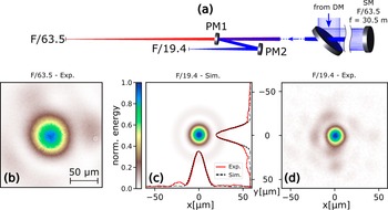
A dedicated on-shot imaging diagnostic, operating at high energies, was designed and implemented to additionally assess laser focus quality at petawatt levels and evaluate the effects of plasma formed on the surface of the mirrors of the DPM system at increasing intensities. This high-power diagnostic (HPD), depicted in Figure 2(a) (and a detailed layout included in Figure S13 in the SI), is designed to attenuate and image the focus of a 10 PW laser beam at full energy and is used with approximately 175 J total energy and approximately 24 fs in duration in this investigation. Following the DPM system, the high-energy beam propagates in vacuum to an uncoated, concave parabolic mirror with 30.5 cm diameter and 2.54 m focal length. The concave mirror is at an incidence angle of 0.25° and reimages the focus in the vicinity of the incoming beam’s focal plane. Two uncoated wedges are used to reduce the energy of the beam before a 4f telescope (1.52 m focal length lenses, aperture 102 mm, F/14.9) that relays the intermediate focus onto an optical table outside the vacuum chamber. The uncoated optics provide five orders of magnitude attenuation to the first lens of the 4f telescope, while the beam passes collimated through the vacuum window. The low fluence (<0.07 mJ/cm2) along the vacuum window, as well as the low B-integral (<0.22), minimizes any unwanted nonlinear effects and other distortions of the image. On the outside optical table, a 5× microscope ultimately images the relay-imaged focus to a complementary metal–oxide–semiconductor (CMOS) detector. The routing mirrors on the outside optical table are silver-coated except for one that is replaced with an uncoated wedge to achieve a total attenuation of seven orders of magnitude at the entrance of the 5× microscope. Further attenuation on the detector is achieved via neutral density filters.
(a) High-power diagnostics layout to image the focus produced by the DPM telescope (red ellipse) during a high-power laser shot up to 10 PW. After the final focus, the beam is first propagated to a large refocusing on-axis parabolic mirror (left) until the intensity is low enough to reflect a small fraction of the laser without triggering a plasma on the optic surface. The reflected light is brought to an intermediate focus next to the incoming beam. The intermediate focus is relay-imaged to a microscope outside the target chamber with a 4f telescope. Before the first lens, the beam is attenuated using two uncoated wedges such that a parallel beam with about 3-inch diameter can safely propagate through the vacuum window. Outside the vacuum, the beam is attenuated across one uncoated wedge and several routing mirrors. Finally, a 5× microscope, similar to the in-chamber downstream microscope, is used to record the focal spot image on shot. The laser beam is p-polarized on the optics of the high-power diagnostic, in contrast to the s-polarization on the DPM system. (b) Simulated Huygens point spread function for the full spectral bandwidth of the laser showing high imaging quality, as confirmed by the simulated Strehl ratio of 0.65. For further details see the text and Section 6 of the SI.
In order to estimate the imaging resolution of the HPD system, ray-tracing simulations have been performed (Figure 2(b)) using OpticStudio. From the calculated Strehl ratio, 0.65, it is anticipated that the measured peak intensity with the HPD system is 35% lower than the actual intensity achieved for the demagnified focus. The limited resolution of the HPD system is attributed to the aperture of the refocusing parabolic mirror and the chromatic aberrations in the relay lenses (see Section 6 of the SI for further details) and was characterized with a USAF 1951 microscope calibration target placed at the focal plane of the F/19.4 beam.
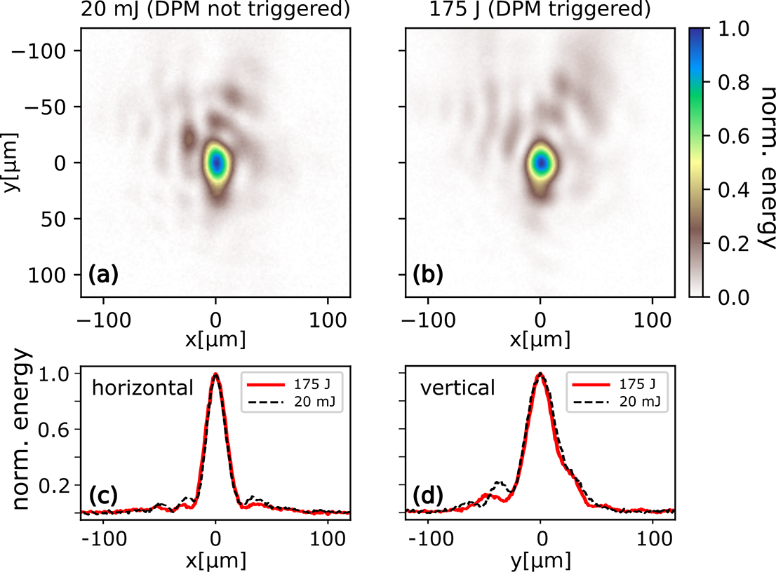
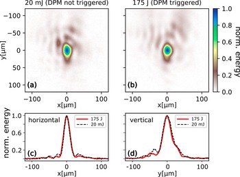
The foci measured experimentally with the HPD system are shown in Figure 3. The system’s performance was initially evaluated by imaging the focal spot at low energy, 20 mJ, using a double-silver-mirror (DSM) system configured in the same way as the DPM (Figure 3(a)). The peak intensity on PM1 resulting from this low energy was less than 2 × 10¹¹ W/cm2, which is below the trigger threshold of the PMs. Silver coating was used in this case to increase the reflectivity of the PMs. Under these conditions, the focus covers a broader area (FWHM (24.6 ± 1.2) μm) and exhibits lower encircled energy ((17.4 ± 2)%) compared to the focus measured in the target chamber (Figure 1(d)). The diminished focus quality can be explained by the limited resolution of the HPD system. Conversely, for an incoming laser light with high energy, 175 J, the intensity on the antireflection coated telescope mirrors reaches values of 1016–1017 W/cm2, which are well above the threshold for plasma formation. In these high-energy conditions, the measured focal spot size using the HPD diagnostic (see Figure 3(b)) was (23.8 ± 1.2) μm, with an encircled energy of (15.3 ± 2)%. These values are comparable to those measured at low energy, indicating that plasma formation on the telescope’s mirrors induces minimal effects on the focus quality of the reflected laser light, as also evidenced from the horizontal (Figure 3(c)) and vertical (Figure 3(d)) lineouts relative to the measured low-energy focal spot. Therefore, the chosen intensity range on the PMs did not affect the spatial profile to a significant degree, similar to the high-energy cases shown by Ziener et al. [ Reference Ziener, Foster, Divall, Hooker, Hutchinson, Langley and Neely10] and Kim et al. [ Reference Kim, Choi, Lee, Janulewicz, Sung, Yu, Kim, Yun, Jeong and Lee36].
(a) Foci measured with the high-power diagnostics at low energy, 20 mJ, using silver-coated mirrors (FWHM: 24.6 ± 1.2 μm; EE: 17.4% ± 2%) and (b) high energy, 175 J, using antireflection coated mirrors (FWHM: 23.8 ± 1.2 μm; EE: 15.3% ± 2%). Close similarities of the normalized horizontal, (c), and vertical, (d), profiles along the center of both foci images demonstrate a minimal distortion of the focal spot when plasma is triggered on the mirror surfaces at high energy. Uncertainties are derived from the daily variation of the focus profile caused by deformable mirror settings and shot-to-shot fluctuation. FWHM, full width at half maximum of the focus; EE, encircled energy within FWHM.
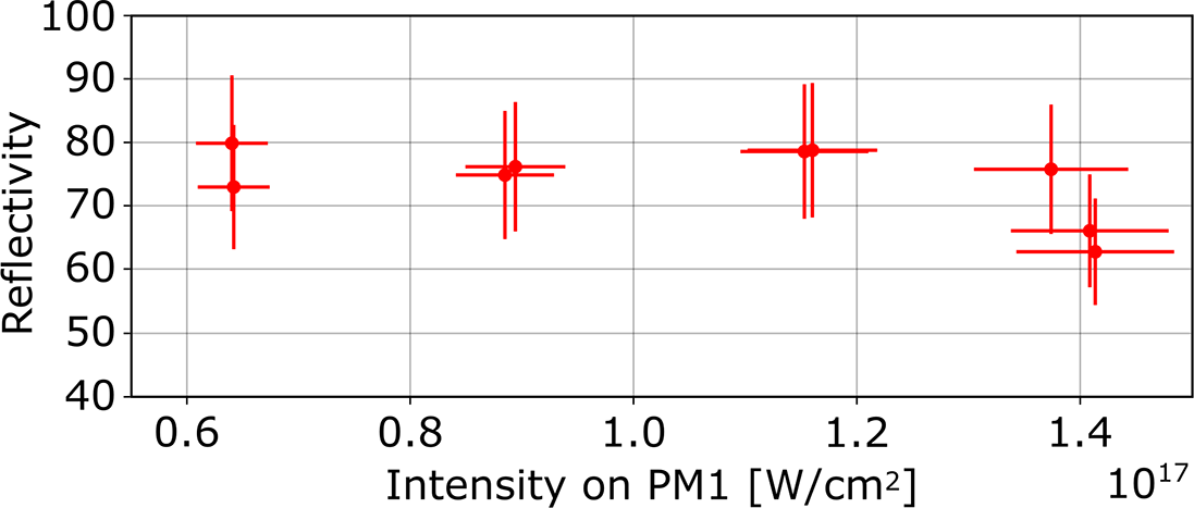
The HPD configuration was additionally employed to characterize the total reflectivity of the DPM system. The DPM reflectivity is determined as the ratio between the incoming energy into the DPM system, which is derived from the energy measurement on the laser diagnostic bench, and the measured energy in the HPD microscope. The signal in the focus image was integrated following the background subtraction procedure detailed in Section 5 of the SI. In the corresponding calibration measurement taken without the DPM system, one neutral density filter was removed from the HPD system to adapt the dynamic range of the camera. This analysis was conducted for laser intensities where efficient plasma formation is expected on the surface of the PM1 mirror, specifically for intensities ranging from 6 × 10¹⁶ to 1.4 × 10¹⁷ W/cm2. The total reflected laser light by the DPM system, as shown in Figure 4, was measured to have an average value of (68 ± 10)%, remaining relatively constant across the considered intensity range. The confidence interval is defined by the uncertainties of the neutral density filters transmission, incoming energy and energy calibration of the microscope camera. These results are in line with previous works by Shaw et al. [ Reference Shaw, Steinke, van Tilborg and Leemans20] and Choi et al. [ Reference Choi, Jeon, Lee, Kim, Kim, Kim, Lee, Yoon, Sung, Lee and Nam24]. Considering equal average reflectivity for each PM, the intensity range on PM2 is calculated to be between 3.1×10¹⁶ to 6.8×10¹⁶ W/cm2.
Measured total reflected laser light on the DPM system as a function of the peak intensity on the first plasma mirror, PM1. Horizontal error bars (intensity on PM1 variation) are defined by the uncertainty in energy measurement at the laser diagnostic bench and pulse duration. Vertical error bars are defined by uncertainties in the transmission of multiple microscope filters used to adapt the dynamic range, incoming energy and energy calibration of the microscope camera.

Based on the focus size measured by a downstream microscope at low energy ((15.5 ± 1.2) μm, Figure 1(d)), along with the total DPM reflectivity ((68 ± 10)%, Figure 4) and pulse duration ((24 ± 1) fs, see Section 7 of the SI), the resulting experimental intensity reaches a value of (8.7 ± 1.9) × 1020 W/cm2. This peak intensity is 8.2 ± 1.8 times higher than (1.1 ± 0.2) × 1020 W/cm2 that could be achieved under the same initial laser conditions without the DPM telescope system.
3 Characterization of the contrast enhancement
The direct laser contrast measurement after the DPM system employing the HPD was hindered by the dispersion caused by two achromat lenses and a vacuum window, which stretch the laser pulse beyond acceptable limits. Consequently, to characterize the on-target temporal intensity laser contrast, we examined proton acceleration from the interaction with thin planar foils. A laser pulse exhibiting low temporal intensity contrast is expected to pre-ionize the target and could diminish the coupling of the main laser beam energy into the pre-heated plasma, thereby reducing both the conversion efficiency to particle generation and the maximum kinetic energy of accelerated ion beams. Conversely, high-contrast laser pulses prevent plasma expansion at an early stage of the laser–target interaction, enabling efficient energy transfer of the laser beam to particle formation and motion[ Reference Gonzalez-Izquierdo, Fischer, Touati, Hartmann, Speicher, Scutelnic, Rivas, Bodini, Fazzini, Günther, Härle, Kenney, Schork, Bruce, Spinks, Quevedo, Helal, Medina, Gaul, Ruhl, Schollmeier, Steinke and Korn38]. This effect is particularly pronounced in nanometer-thick targets. To evaluate the contrast enhancement at the F/19.4 configuration, ultrathin planar carbon foils (~5 nm thick) were irradiated at a 45° incidence angle using high-energy laser pulses ((174 ± 10) J before the DPM system). The energy spectra of the accelerated proton beams were measured at specific discrete energies using a radiochromic film (RCF) stack placed approximately 50 mm downstream from the target and designed to capture the entire beam profile. Alongside the RCF, a Thomson parabola ion spectrometer was employed to provide complementary measurements of the proton spectrum along the target normal direction. Dedicated measurements were conducted using both the DPM system and an identically configured DSM system. Silver-coated PMs were chosen for their high reflectivity at the laser wavelength (760–860 nm), enabling them to also reflect the preceding signals of the laser pulses (highlighted area in Figure S4(b) of the SI) as opposed to the antireflective coating of the PMs. Meanwhile, the part of the laser pulse that arrives after the highlighted box is reflected to a similar extent by the plasma for both antireflective and silver coatings. Therefore, the DSM system serves as a control case where the temporal intensity contrast of the reflected beam is expected to maintain similar values before and after reflection.
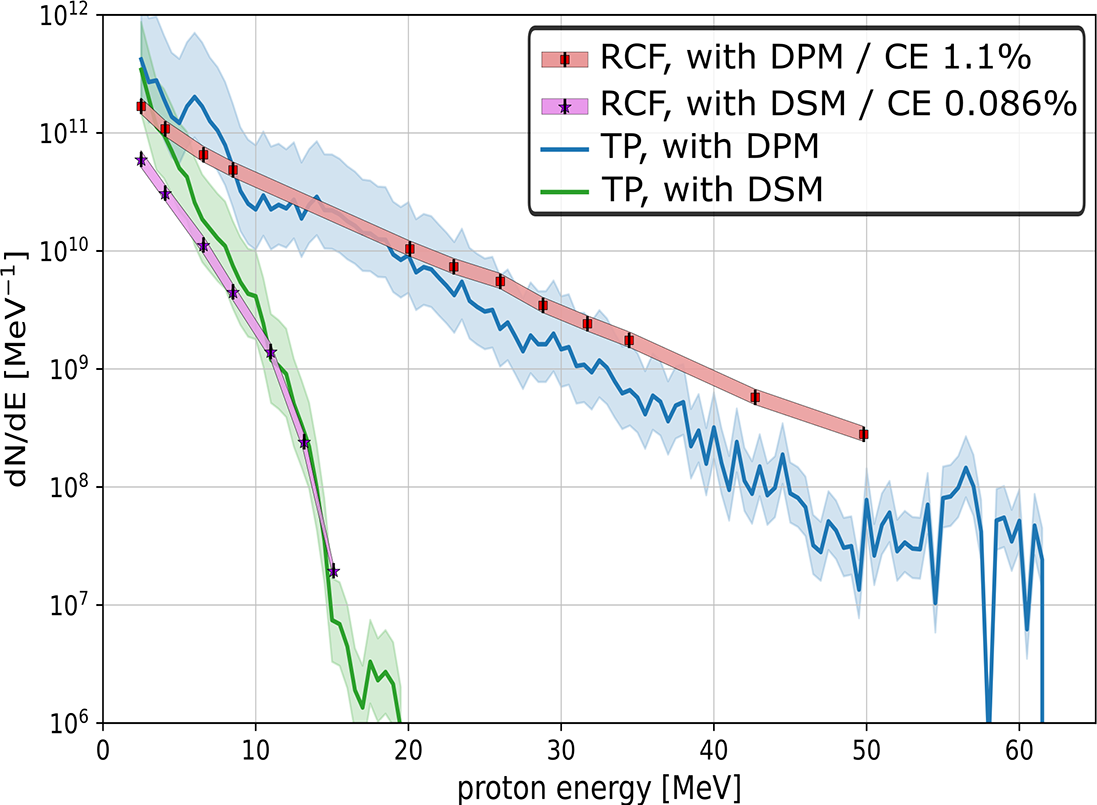
The proton spectra measured from the RCF and the Thomson parabola detectors, using the DPM and DSM systems, are shown in Figure 5. The total proton yield, conversion efficiency and maximum kinetic energy show a significant increase when using the DPM system compared to the DSM system (i.e., without enhanced laser contrast). Even at this minimal target thickness the DSM system generates a proton beam with energies up to 20 MeV, highlighting the inherently high contrast of the laser system. Conversely, in the case of the DPM system, notably higher proton yield, conversion efficiency (up to 1.1%, compared to 0.086% in the DSM case, representing an increase of nearly two orders of magnitude) and maximum kinetic energy are produced, generating proton energies exceeding 60 MeV. Both the RCF and Thomson parabola detectors show good agreement in proton spectra, including particle number and maximum proton energy. These results therefore provide evidence for a substantial enhancement of the temporal intensity contrast by the DPM system and demonstrate its feasibility for applications involving ultra-intense laser light and nanometer-scale solid targets.
Proton spectra from approximately 5 nm thick carbon foils. Spectra calculated from the measured RCF data with the DPM and DSM systems (at F/19.4) are represented by red squares and purple stars, respectively. The shaded areas and the vertical error bars of the RCF data correspond to the uncertainty in the calibration of the RCFs. Thomson parabola (TP) spectra with the DPM and DSM systems are represented by blue and green lines, respectively. The corresponding error bars are determined by the extrapolation of the beam divergence from the RCF to the TP. The DPM system shows a significantly higher proton cut-off energy (>60 MeV), total particle number and conversion efficiency (CE), highlighting a marked improvement in the temporal intensity contrast compared to the DSM case.
4 Conclusion
A DPM telescope system, using commercially available spherical optics, has been implemented and characterized for its ability to adjust intensity and to enhance temporal contrast in a multi-petawatt laser beamline. A reduction from F/63.5 to F/19.4 with minimal aberrations at the image plane has been experimentally demonstrated. The aberrations introduced by each of the spherical mirror surfaces of the telescope system are compensating each other, resulting in a small astigmatism that is manageable by minor and predictable adjustment of a deformable mirror, as shown by measurements at low powers of the laser.
The focus quality at high energy levels was evaluated using an imaging system diagnostic with seven orders of magnitude attenuation. This diagnostic revealed that no significant changes of the focus quality are observed for low- and high-energy regimes, indicating that the triggered plasma has minimal impact on the DPM telescope system’s focusing optical properties. Employing this diagnostic, the total reflectivity of the DPM telescope system was also characterized, measuring an average value of (68 ± 10)%. These results evidence an approximately 8.2 times increase in peak intensity at the focal plane to (8.7 ± 1.9) × 1020 W/cm2 compared to (1.1 ± 0.2) × 1020 W/cm2 that could be obtained with a setup lacking the DPM telescope system. This substantial intensity enhancement was achieved without requiring expensive or labor-intensive modifications to the large-aperture focusing optics of the 10 PW laser beam delivery line.
In addition, to characterize the temporal intensity contrast at the focal plane, dedicated laser interactions with ultrathin planar targets were performed using the DPM telescope system and compared to a system with silver-coated mirrors (otherwise identical to the DPM system), resulting in proton acceleration with a cut-off energy of more than 60 MeV and approximately 20 MeV, respectively. Besides, the laser-to-proton energy conversion efficiency increased by more than an order of magnitude when the DPM system was used. Confirmation of these findings from two independent proton detectors, RCF and Thomson parabola, supports that the temporal intensity contrast is significantly enhanced after reflection from the DPM telescope system, compared to the intrinsic laser contrast, thereby enabling efficient laser–energy coupling with irradiated targets.
The implemented DPM telescope system offers relatively low-cost intensity adjustability and contrast enhancement of a multi-PW laser beam, while maintaining low aberrations at the focal plane and low sensitivity to misalignment. The validity of this system, combined with the ease of producing spherical optics in large quantities, sets thus a benchmark for expanding the capabilities of terawatt to multi-PW laser facilities to achieve higher intensities without altering the beamline optics while enabling the exploration of more extreme laser–plasma conditions for applications that require ultra-high temporal contrast and intensity, particularly in cases involving ultrathin, near-critical density, or nanostructured targets.
Acknowledgements
Jens Hartmann is acknowledged for microscope design and fruitful discussions. Daniel Popa and Bogdan Tatulea are acknowledged for technical support.
The Extreme Light Infrastructure – Nuclear Physics (ELI-NP) team acknowledge the support of the Romanian Government and the European Union through the European Regional Development Fund - the Competitiveness Operational Programme (1/07.07.2016, COP, ID 1334), and the Romanian Ministry of Research, Innovation and Digitalization: PN23210105 (Phase 2, the Program Nucleu). Accessing the ELI-NP facility is supported by the IOSIN Funds for Research Infrastructures of National Interest funded by the Romanian Ministry of Research, Innovation and Digitalization.
M.T. and L.G. acknowledge the support of the Czech Science Foundation through grant GACR24-11398S.
Competing interests
V.S., M.Sp., A.F., B.G.-I., J.J.B., C.B., G.B., A.B., A.C., J.D’M., F.D., M.E., D.Ge., M.Gu., O.J., K.K., S.K., M.M.-P., N.P., H.R., E.S., M.St., Sv.S., A.U., E.G., D.R., M.Sc. and G.K. are employed at Marvel Fusion GmbH. A.A., O.C. and C.D. are employed by Thales LAS France.
Supplementary material
The supplementary material for this article can be found at http://doi.org/10.1017/hpl.2025.10076.


 Open access