


1. Introduction
Ultra-intense laser systems are being developed by a number of institutions to use the full potential of deuterated potassium dihydrogen phosphate (DKDP) for high-energy optical parametric chirped-pulse amplification (OPCPA)[ Reference Ross, Matousek, Towrie, Langley and Collier1– Reference Hu, Wang, Xu, Yu, Wu, Zhang, Yang, Ji, Bai, Liang, Leng and Li5]. Noncollinear optical parametric amplifiers (NOPAs) based on large DKDP crystals produce broadband gain for supporting pulses as short as 10 fs. Although OPCPA is now routinely used as a broadband front-end technology, scaling OPCPA to more than 100 J is still an active area of research.
This paper reports on the multi-terawatt (MTW) optical parametric amplifier line (OPAL) laser system, a midscale OPAL pumped by the MTW laser, where the long-term goal is building the EP-OPAL a femtosecond−kilojoule system to add to the OMEGA Laser Facility. MTW-OPAL was designed to produce 7.5-J, 15-fs pulses and demonstrate technologies that are suitable for kilojoule all-OPCPA systems that could be pumped by OMEGA EP. The architecture of the system is described and results are presented for 0.35-PW operation corresponding to 7.3-J, 20-fs pulses. Plans for further development are outlined. In addition to being a critical platform for laser development, the MTW-OPAL laser shares a target area with the existing MTW Laser System (50 J, 1 to 100 ps) and the auxiliary laser for the underdense plasma chamber (UDP-E, 527 nm, 5 J, 2 ns), making possible several joint-shot configurations.
2. EP-OPAL concept
2.1. System overview
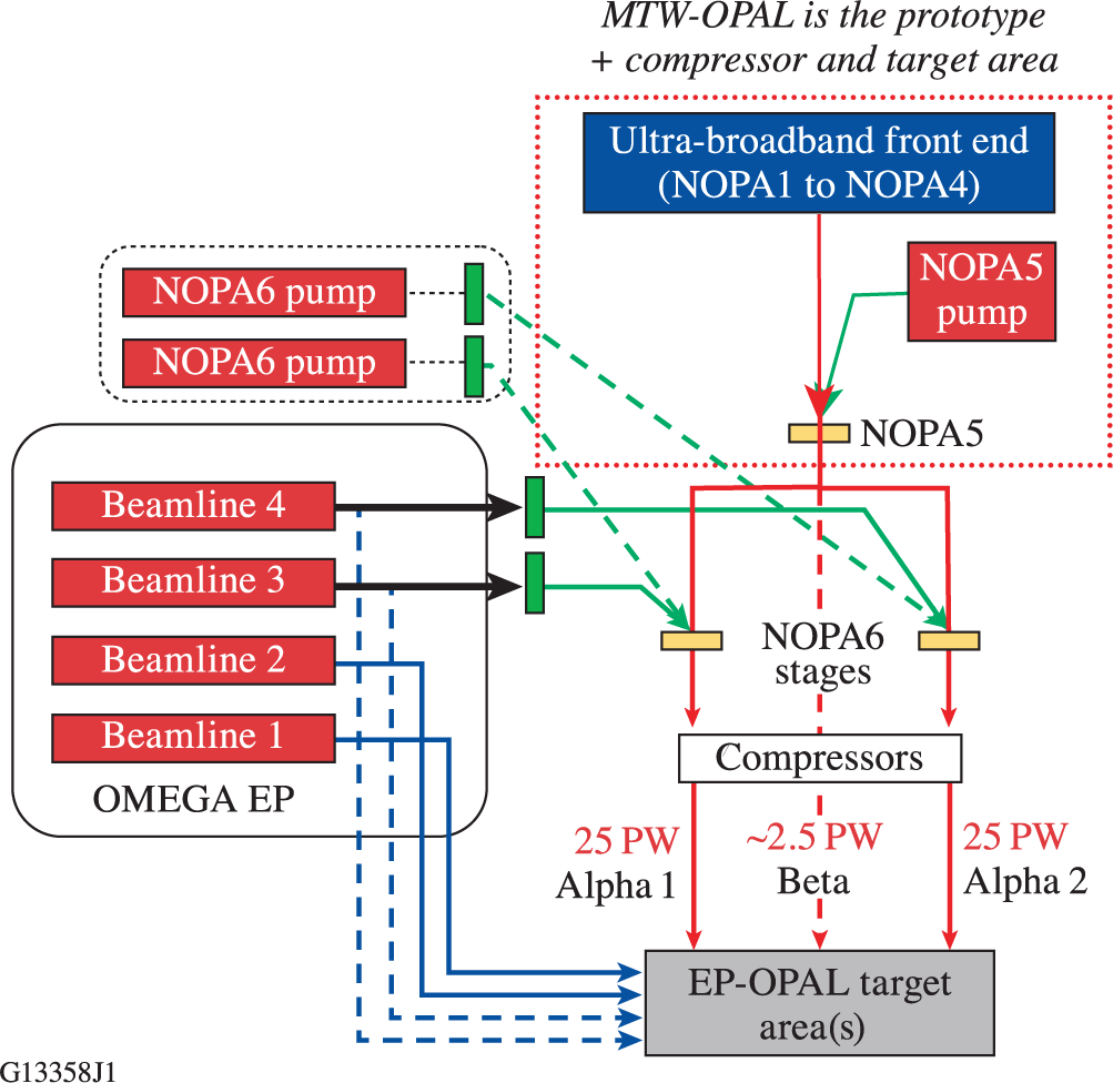
It is important to review the EP-OPAL concept so that design choices made for the MTW-OPAL system, and constraints that were applied to the project, can be understood. EP-OPAL, shown schematically in Figure 1, will use an all-OPCPA approach to deliver two 25-PW beams to two target areas for focused intensities more than 5 × 10²³ W/cm2. In place of one of the 25-PW “Alpha” beams, a “Beta” beam with a peak power of 2.5 PW will be available for longer-focal-length, lower-peak-power applications, such as laser-plasma wakefield acceleration of electrons. The science case for EP-OPAL includes experiments where primary beams (optical) and secondary beams (high-energy photon or particle) are collided in the target chambers to explore a variety of high-intensity phenomena[ 6, Reference Falcone, Albert, Beg, Ditmire, Glenzer, Haefner and Zuegel7]. Therefore, the system will be designed so that the 500-J, 20-fs pulses from each beam can be co-timed and co-pointed with high precision. The schematic shown in Figure 1 presents one strategy to simplify this, namely the use of a common front end and penultimate amplifier stage, NOPA5, for all the beams. The dual-beam system is a significant upgrade from the original single-beam concept[ Reference Danson, Hillier, Hopps and Neely8, Reference Meyerhofer, Bahk, Bromage, Froula, Haberberger, Hu, Kruschwitz, McCrory, Myatt, Nilson, Oliver, Stoeckl, Theobald, Waxer and Zuegel9]. Furthermore, two target areas will be included: one for high-intensity experiments, where the EP ultraviolet (UV) beams are available, and the other with more flexible focusing geometries and long focal lengths for high f-number experiments.
EP-OPAL schematic showing two options for pumping the final amplifiers, NOPA6, for the two 25-PW beamlines that are seeded by a common front end.

Two concepts for pumping the final NOPA6 stages in the Alpha beamlines are being considered. The first is to use existing OMEGA EP beamlines (3 and 4) to pump each stage. The second is to add two new pump lasers (shown in Figure 1 with dashed lines). In both cases, new liquid-cooled Nd:glass amplifiers will be developed to reduce the time between shots to less than 5 min, similar to the approach demonstrated in the L4 ATON laser at ELI-Beamlines[ Reference Gaul10, Reference Chériaux, Gaul, Antipenkov, Borger, Green, Batysta, Friedman, Jochmann, Kramer, Rus, Trojek, Vyhlídka and Ditmire11]. Increasing the shot rate improves the scientific productivity, enabling a statistical approach not typical for kilojoule-scale systems. Furthermore, reducing the time between shots helps the laser operators ensure that optimum laser parameters are achieved and maintained with closed-loop feedback (e.g., dispersion tuning or adaptive focusing).
The MTW-OPAL Laser System, the focus of this paper, has an architecture essentially identical to the planned front end of EP-OPAL with the addition of a compressor and target area. Adding the compressor was critical for evaluating the performance of the UFE and the amplifier stages (e.g., testing pulse compressibility) and for developing systems that characterize the full-power pulses. Delivering MTW-OPAL pulses to the MTW target chamber enables a variety of joint-shot experiments with the existing picosecond and nanosecond beams, to both develop relevant targeting and experimental diagnostics concepts and train the scientists and target-area engineers required for the full-scale EP-OPAL system.
2.2. Technical challenges and critical technologies
The EP-OPAL conceptual design depends on resolving a number of technical challenges to achieve peak powers approaching 25 PW and focused intensities up to 5 × 10²³ W/cm2 in two beams that can be co-pointed and co-timed with high precision (i.e., to a fraction of the diffraction-limited focal spot and Fourier transform-limited pulse width, respectively). A number of technical challenges were identified during the preconceptual design, and the MTW-OPAL architecture was chosen to address them at a midscale level with a 90-mm2 beam, approximately 1/9 the size of the EP-OPAL beams after compression.
The design of the MTW-OPAL’s final amplifier, a 63-mm2 DKDP crystal, was selected for scalability to the EP-OPAL’s 370-mm beams at NOPA6. The pump and signal intensities are comparable, and the beam-combination technique using a dichroic mirror can be scaled to kilojoule energies for crystals ranging in deuteration from 70% to 100%. Technologies in the front and back ends for dispersion control and spatially resolved spectral phase measurement diagnostics have been integrated to ensure optimum pulse compression. A number of optical coatings have been developed at LLE[ Reference Oliver, Bromage, Smith, Sadowski, Dorrer and Rigatti12] using electron-beam deposition techniques that are scalable to the full EP-OPAL aperture, which requires an 800-mm2 beam after compression (full width at 1%). The MTW-OPAL compressor provides a platform for testing gratings with beams that are either p-polarized, as required for traditional gold-coated gratings, or s-polarized for hybrid dielectric-on-metal gratings that may be available in the future with higher diffraction efficiency and/or damage thresholds[ Reference Bonod, Hervy, Mouricaud, Djidel, Cotel, Desserouer, Chambaret, Somekh, Chériaux, Mathieu and Le Blanc13– Reference Wang, Jin, Ma, Sun and Jing17]. A secondary vacuum chamber will be added to MTW-OPAL with a deformable mirror for focal-spot optimization and a double-plasma mirror system for temporal contrast improvement. Finally, in situ damage testing of coatings and gratings with large-aperture (>1-cm) beams will reduce the risks associated with applying damage test results obtained with millijoule-level systems to kilojoule-level lasers.
3. MTW-OPAL overview
A schematic of the MTW-OPAL Laser System is shown in Figure 2. The top half shows the MTW laser with subsections highlighted that are used to pump the final stage of the OPAL, shown in the bottom half. The ultra-broadband front end (UFE) for the OPAL produces 250-μJ pulses at 5 Hz. The pulses have 200 nm of bandwidth (full width at 10%) and are compressible to sub-15 fs. They are stretched to 1.5 ns for further amplification: first, in the NOPA4 stages (pumped at 5 Hz) to 150 mJ and, then, in the final NOPA5 stage to 11 J. The diagnostic compressor package (DCP), located between NOPA4 and NOPA5, can be used to compress the output of NOPA4 for diagnostic development and system optimization.
The MTW-OPAL system in relation to the existing MTW laser. The MTW laser is reconfigured using three switchyards. Portions of the MTW laser that are not used for pumping the final amplifier stage of the OPAL (NOPA5) are shown in gray. UFE, ultra-broadband front end; DCP, diagnostic compressor package; OPA, optical parametric amplifier.

Demonstrating large-aperture OPCPA using DKDP is one of the primary goals of the MTW-OPAL project. DKDP is used in NOPA5 to amplify 45-mm2 beams, and the broadband spectrum of the system is centered at approximately 920 nm to match the spectral range of the amplifier gain. Previous amplifier stages have smaller beam sizes (<7 mm); therefore,
![]() -barium borate (BBO) was selected for its higher nonlinearity coefficient (d
eff) with more gain per unit length for a given pump intensity[
Reference Dmitriev, Gurzadyan and Nikogosyan18].
-barium borate (BBO) was selected for its higher nonlinearity coefficient (d
eff) with more gain per unit length for a given pump intensity[
Reference Dmitriev, Gurzadyan and Nikogosyan18].
NOPA4 and NOPA5 are independently pumped using separate Nd:doped lasers that are electrically synchronized. The two NOPA4 stages are pumped using a frequency-doubled 5-Hz Nd:yttrium lithium fluoride (YLF) laser system; NOPA5 is pumped using the MTW system. Three switchyards are used to configure MTW to provide narrowband, 80-J pump pulses at 1053 nm. After frequency conversion, 40-J pulses at 526.5 nm are transported through the wall that separates the MTW and OPAL systems to the NOPA5 stage.
The broadband beam is image relayed between the OPAL amplifier stages using lens-based vacuum spatial filters (not shown in Figure 2). The radial group delay compensator (RGDC) compensates for the chromatic aberration that would otherwise lead to spatiotemporal distortions and a minimum compressed pulse duration (averaged over the entire beam) of more than 100 fs. This improves the final spatiotemporal focus and eliminates phase-matching issues in NOPA5 that could arise if the beam has significant chromatic aberrations.
After NOPA5, the pulses propagate through a vacuum window into the femtosecond compressor chamber. The beam is expanded using an all-reflective, achromatic image relay (AIR) that is free of chromatic aberrations[ Reference Schiesser, Bahk, Bromage and Rolland19]. The chamber contains a four-grating vacuum compressor, optics to provide sample beams for laser diagnostics, and optics to transport the beam to a target chamber in an experimental area that supports both the MTW and OPAL for joint-shot campaigns.
4. MTW-OPAL subsystems
MTW-OPAL consists of several subsystems, starting with the UFE and ending with pulse compression and transport to the target chamber. Each subsystem has a role to play in addressing the technical challenges for building an ultra-intense OPCPA laser system.
4.1. Ultra-broadband front end
The UFE system is described in detail in Refs. [Reference Bromage, Roides, Bahk, Mileham, McIntire, Dorrer and Zuegel20, Reference Bromage, Bahk, Begishev, Dorrer, Guardalben, Hoffman, Oliver, Roides, Schiesser, Shoup, Spilatro, Webb, Weiner and Zuegel21], and the architecture and operating parameters have not changed significantly. Broad-bandwidth seed pulses are produced from a self-focusing filament generated in an undoped yttrium aluminum garnet (YAG) crystal generated using a Yb-doped fiber chirped-pulse amplification (CPA) laser. The 200-nm-wide portion of the white-light continuum around 920 nm is amplified by the subsequent NOPAs. Several activation campaigns were used to optimize the UFE configuration for best-overall system performance, such as iterative adjustment of the acousto-optic programmable dispersive filter (DAZZLER®)[ 22] dispersion to ensure best compression at full energy. The results of these campaigns are shown in Section 5.
4.2. NOPA4 amplifier stages
NOPA4 consists of two separate BBO crystals: a preamplifier and a power amplifier. They are pumped with separate beams from a Nd:YLF laser that is electronically synchronized with the UFE and the MTW laser. The 5-Hz NOPA4 pump laser is very similar to those used to pump the OPCPA stages of MTW and OMEGA EP[ Reference Bagnoud, Guardalben, Puth, Zuegel, Mooney and Dumas23]. For maximum OPCPA efficiency, the pump pulses are shaped as high-order super-Gaussians to be flat in space and time. The fiber front end for the pump laser contains an arbitrary waveform generator for shaping a 1.5-ns pulse to precompensate for gain saturation within the Nd:YLF regenerative amplifier and Nd:YLF ring amplifier. The pump pulses are frequency doubled in 8-mm-thick lithium borate (LBO) with 70% conversion efficiency before being split and image relayed to two crystals: NOPA4a (10 mm thick) and NOPA4b (5 mm thick). The first is a preamplifier that increases the energy of the stretched pulses from 200 μJ to 20 mJ. The second is a power amplifier that increases the energy to 150 mJ. The pump-pulse energies for these stages are 70 and 450 mJ, respectively.
Although the design of the NOPA4 stages has not changed since it was described in detail in Ref. [Reference Bromage, Bahk, Begishev, Dorrer, Guardalben, Hoffman, Oliver, Roides, Schiesser, Shoup, Spilatro, Webb, Weiner and Zuegel21], some components have been modified and the operating points changed, primarily to reduce the incidence of optical damage. For example, we exchanged the BBO crystals for ones with higher surface quality[ 24] to overcome optical degradation after prolonged use.
4.3. Diagnostic compressor package
The DCP is used to study the compressibility and temporal contrast of the pulses from NOPA4 after they have been intercepted using a switchyard mirror. The compressor within the DCP uses two gratings with 1285 lines/mm groove densities (G1 and G2) and a roof mirror (RM) in the standard double-pass configuration. Gold-coated, holographic gratings, identical to those required for the final vacuum compressor, are used to compress pulses to less than 20 fs, which are measured using SPIDER[ Reference Dorrer, de Beauvoir, Le Blanc, Ranc, Rousseau, Rousseau and Chambaret25, Reference Iaconis and Walmsley26].
The DCP beam is approximately 40% the size of the full-energy beam from NOPA5 that will be sent to the four-grating vacuum compressor. Therefore, the DCP can use a double-pass, two-grating configuration, which is more compact and less expensive. The DCP was a critical subsystem during activation and “first light,” enabling front-end performance to be tested and optimized while the back end was under construction. More recently, the DCP has been used for several laser-characterization campaigns; for example, it was used to measure the impact of high-frequency noise (present on the pump pulse in two-stage OPCPA systems) on the temporal contrast of compressed pulses[ Reference Feng, Dorrer, Jeon, Roides, Webb and Bromage27].
4.4. NOPA5 amplifier stage
NOPA5 is the last NOPA stage in the MTW-OPAL Laser System. It is pumped using 1.5-ns pulses at 527 nm from MTW, when operated in a narrowband mode, where the OPCPA portion of the MTW laser is bypassed, as shown in Figure 2. The MTW laser can be fired once every 20 min, set by the cooldown time of the 150-mm-aperture, Nd:glass disk amplifier[ Reference Bagnoud, Puth, Begishev, Guardalben, Zuegel, Forget and Le Blanc28]. Upgrading this amplifier using liquid-cooled disks could potentially reduce the shot-cycle time to the 2-min duration set by the preceding Nd:glass rod-amplifier stage.
The size, super-Gaussian order and uniformity of the pump beam at the NOPA5 crystal are adaptively optimized using a liquid crystal-based programmable spatial light modulator system[ Reference Bahk, Begishev and Zuegel29]. Similarly, the arbitrary waveform generator in the fiber front end was adjusted to create a high-order super-Gaussian temporal pulse (N ~ 34). Figure 3 shows the resulting flattop fluence and optical power profiles. This combination delivers a pump intensity that is uniform in space and time for maximum pump-to-signal transfer efficiency.
(a) Measured pump-beam profile after correction using a liquid crystal-based, programmable spatial light modulator (PSLIM). (b) Measured pump-pulse shape after correction using an adaptive pulse-shaping system in the MTW front end, with a fit to a 34th-order super-Gaussian.

(a) Photograph and (b) schematic of the NOPA5 amplifier showing top and side views of the geometry required to achieve pump−signal beam combination with a subdegree noncollinear angle (angles exaggerated).

(a) An example of tuning-curve measurements at the optimum noncollinear angle (0.32°) for a nominal 70% deuteration level where the gain peaks for the two wavelengths are aligned. (b) Measured versus nominal deuteration levels for all tested crystals with error bars showing the 95% confidence interval.

Figure 4 shows the two periscope assemblies that use dichroic mirrors to combine the pump and seed beams before the amplifier and to separate residual pump light after the amplifier. The broadband signal beam is vertically polarized and passes through the lower mirror at Brewster’s angle. The pump is horizontally polarized and the crystal is rotated about a vertical axis for Type-I phase matching. Although the system was designed for deuteration values of 90% or greater, only 70% deuterated crystals were available for first light at the required clear aperture for the approximately 45-mm2 beams. Boules for 95% crystals are currently being grown[ 30], and we expect to upgrade the system in mid-2022. This range of deuteration values requires a change in the internal noncollinear angle between the pump and signal k vectors of the order of 1° to attain the broadband phase-matching condition, where lower deuteration values require that the beams are closer to collinear. Covering this range of internal noncollinear angles using the dichroic beam-combination system is straightforward with only minor pointing adjustments.
A two-wavelength tuning technique was developed for in situ characterization of DKDP crystals[ Reference Dorrer, Begishev, Bahk and Bromage31]. Sub-aperture crystals (25 mm × 25 mm × 48 mm) with nominal deuteration values of 80%, 92% and 98% and two full-aperture 70% crystals (63 mm × 63 mm, 48 or 52 mm thick) were characterized. Figure 5 shows examples of the tuning curves for the optimum noncollinear angle and a comparison of the nominal versus measured deuteration levels that were inferred for the four tested deuteration levels. Predictive, self-consistent models were developed using these experimental results to analyze and optimize the NOPA5 stage performance, as presented in the next section.
The idler beam passes through the output dichroic mirror but it is blocked by a custom short-wavelength pass filter that was designed and manufactured at LLE for this project. Additional idler rejection is achieved by using a large iris in the far-field plane of the following AIR and by the low diffraction efficiency of the gratings at the idler wavelengths.
4.5. Ultra-broadband transport
“Ultra-broadband transport” refers not to a specific subsystem but rather the components and strategies required to propagate pulses from the start of the UFE, through the amplifier stages via the image relay optics, into the vacuum compressor chamber, and onto the focal spot at the target location.
The RGDC, shown schematically in Figure 6, uses an all-reflective spherical Offner triplet to image the beam through two negative lenses to cancel the longitudinal chromatic aberration that is introduced by the positive lenses used in the image relays between the amplifier stages[ Reference Bahk, Bromage and Zuegel32]. Longitudinal chromatic aberration introduces radial group delay[ Reference Bor33, Reference Heuck, Neumayer, Kühl and Wittrock34] that, if not corrected, would increase the duration of the compressed pulse from less than 20 fs to more than 100 fs. A number of techniques have been demonstrated to compensate for this spatiotemporal aberration[ Reference Kessler, Huang and Weiner35, Reference Gaul, Martinez, Blakeney, Jochmann, Ringuette, Hammond, Borger, Escamilla, Douglas, Henderson, Dyer, Erlandson, Cross, Caird, Ebbers and Ditmire36]. For this system, an RGDC was developed that uses two negative plano-concave lenses located before the NOPA5 amplifier in an Offner imaging system to reduce the radial group delay variation on the output pulse to less than 2 fs[ Reference Dorrer, Begishev, Bahk and Bromage31]. A spatially resolved spectral interferometry technique has been developed to test this approach[ Reference Bahk, Dorrer, Roides and Bromage37].
Schematic of the refractive image relays from the output of the UFE to the input of the compressor showing amplifier and image plane locations. The inset shows the predicted RGD with and without the compensator.

(a) Broadband niobia/hafnia/silica multilayer dielectric coating that was optimized for the MTW-OPAL wavelength range. (b) A broadband-enhanced metal reflector (BEMR) that provides adequate reflectivity (98% versus 99.5%) and is necessary for p-polarized applications.

After amplification in NOPA5, the beam is apodized and propagates through a window into a large vacuum system that contains all subsequent optics. The AIR uses four spherical mirrors in a low-aberration configuration to image relay NOPA5 to the vacuum compressor with a 2× beam expansion[ Reference Schiesser, Bahk, Bromage and Rolland19, Reference Schiesser, Bahk and Rolland38].
The ultra-broadband transport system also addresses the challenge of developing short-pulse coatings. Before the vacuum compressor, broadband mirrors are required for s-polarized, 1.5-ns pulses, propagating in air and vacuum with fluences up to approximately 1 J/cm2, for which dielectric mirrors have been developed. After the compressor, mirrors capable of transporting 20-fs pulses in vacuum with nominal fluences of 100 mJ/cm2 are required, suitable for both s- and p-polarizations. Figure 7 shows schematics of the two coating types along with their pros and cons. Small-scale prototypes for the required coatings have been manufactured and tested at both 800 and 920 nm. Full-size mirrors (178 mm × 127 mm) for the 90-mm2 beam were coated with a design optimized for 920 nm in an LLE e-beam coating chamber that was designed to have a layer uniformity of less than 0.1% over the 300-mm coating area[ Reference Oliver, Bromage, Smith, Sadowski, Dorrer and Rigatti12].
4.6. Grating compressor chamber
The grating compressor chamber (GCC) was developed to provide a large, stable platform for the compressor optics (see Figure 8). Cleanliness standards for fabrication techniques and permitted contents followed those developed for OMEGA EP. Detailed analysis of the breadboard stability and vibration sources was completed using finite element analysis. A lid-lift mechanism was designed that provided access to all sides of the chamber. A coordinate measuring machine (FaroArm®) was used to install the optics and beam-alignment apertures to provide a starting point for fine alignment with submillimeter, submilliradian precision.
Computer aided design drawing of the grating compressor chamber (GCC). Inset: finite element analysis of the monolithic breadboard, which is supported by eight legs that are mechanically isolated from the main vessel using vacuum bellows.

Schematic of the grating compressor chamber showing the major subsystems and main beam path (dark blue); the pre-shot, low-energy beam path for shot setup (orange); and the diagnostic beam paths used for on-shot diagnostics (light blue). Inset: the location of the NOPA5 apodizer used to define the beam edges and the sample beam that is picked off for the vacuum SPIDER measurement.

The GCC contains several subsystems. The primary one is the four-grating compressor that provides full-energy dispersion compensation at the end of the system for compressing the 1.5-ns pulses from NOPA5 to less than 20 fs. Figure 9 shows this portion of the system, including NOPA5, the AIR, the grating compressor itself, the short-pulse diagnostics package (SPDP) and the output to the target chamber.
The inset in Figure 9 shows the location of the NOPA5 apodizer used to define the beam edges and the sample beam that is picked off for the vacuum SPIDER measurement. Space has been left for a future pulse conditioning chamber (PCC), located next to the northeast corner of the GCC. A pair of kinematic mirrors can be moved to allow the beam to pass into the chamber for contrast improvement using a double-plasma mirror system and wavefront correction using a deformable mirror.
The compressor uses a four-grating configuration, consisting of two pairs of parallel gratings, which is better suited to the 90-mm2 beam than the two-grating design of the DCP that requires an RM. Right-angle periscopes before and after the compressor will be used to rotate the beam. This is necessary because gold gratings, the only type currently commercially available, are optimized for input beams that are p-polarized. This type of grating is etched into a dielectric substrate that is then overcoated with gold to increase the reflectivity over the bandwidth.
Advanced “hybrid” gratings, consisting of a dielectric grating that is written on top of a metal reflective layer, have been proposed with the goal of increasing the damage threshold while providing increased bandwidth and diffraction efficiency for sub-20-fs pulses[ Reference Bonod, Hervy, Mouricaud, Djidel, Cotel, Desserouer, Chambaret, Somekh, Chériaux, Mathieu and Le Blanc13– Reference Wang, Jin, Ma, Sun and Jing17]. To accommodate this, should such advanced gratings become available at the required sizes (120 mm × 345 mm), the beam transport before and after the vacuum compressor will permit in-line periscopes and turning mirrors to be used (instead of the right-angle periscopes) to preserve the input s-polarization state through the compressor.
5. Preliminary results
Table 1 summarizes the overall system performance achieved thus far. The higher-than-expected efficiency of NOPA5 and transmission through the GCC enabled the use of lower-than-intended pump energies for NOPA5 while still exceeding the design goal of more than 7 J at the output of the GCC. The bandwidth of the UFE and NOPA4 stages was close to the design point; however, the bandwidth after NOPA5 is narrower than what the GCC was designed to support (830 to 1010 nm). This is a consequence of the 70% deuteration level of the NOPA5 DKDP crystal, the highest level that was commercially available to support the first-light schedule with sufficient size and quality.
Summary of primary results and design goals for the MTW-OPAL Laser System.
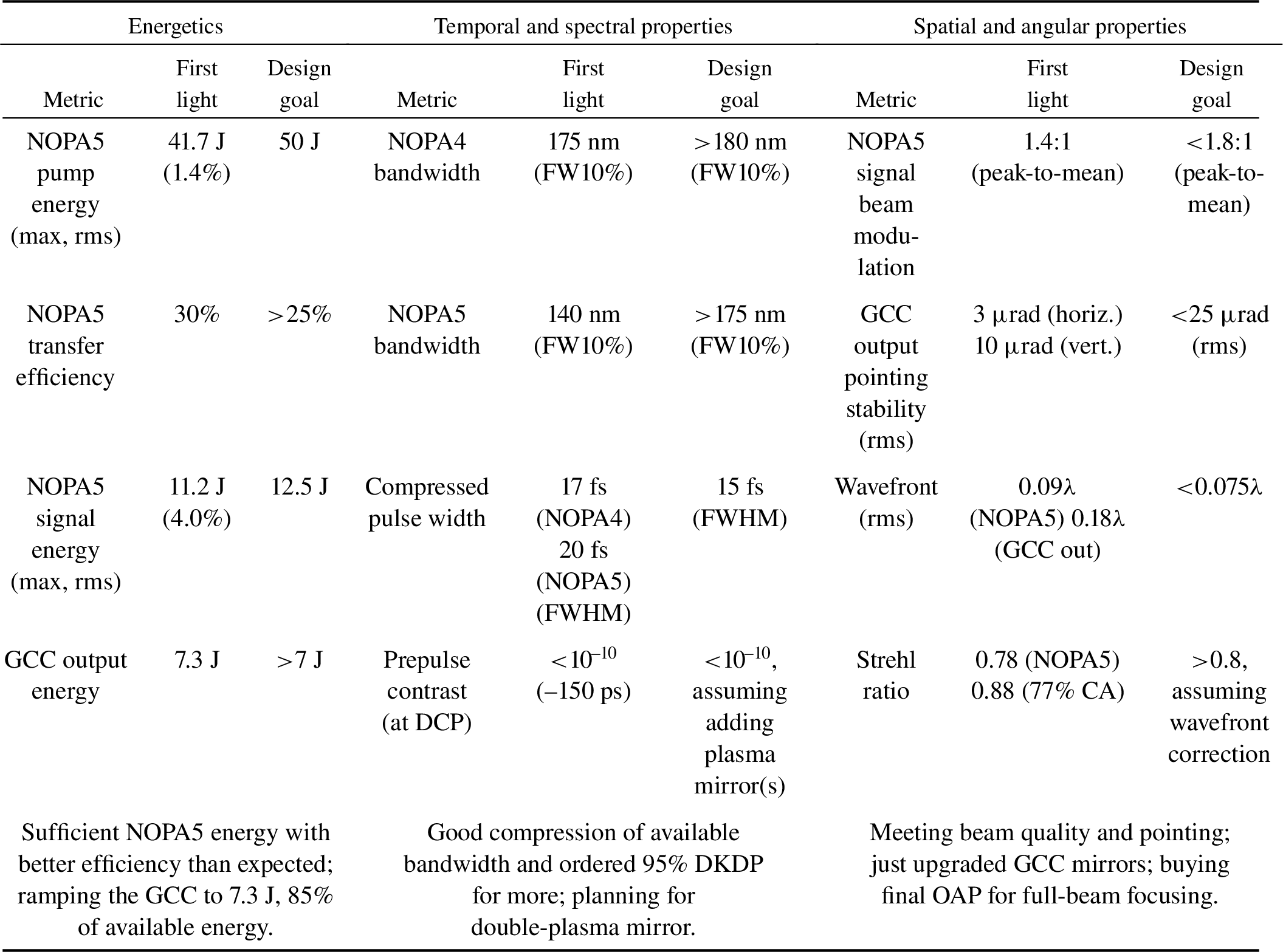
Preliminary measurements of the focusability of the beam have been completed using an off-axis parabola (OAP) with sufficient clear aperture for 77% of the beam area. A spatial Strehl ratio of 0.88 was measured without adaptive wavefront correction that could be achieved, for example, using a deformable mirror. At the time of writing, a full-aperture f/2 OAP had just been received and shots were planned for a first-focus campaign to evaluate the intrinsic focusability of the beam before proceeding with integrating a deformable mirror in the new PCC.
Figure 10 shows measurements and simulation results for the NOPA5 stage for a range of pump-pulse energies. Three-dimensional models that were refined using the sub-aperture crystal testing provided predictive capability for both gain and the amplified spectra, where only the crystal axis angle was adjusted as a fitting parameter. Figure 10 shows increased saturation resulting in more square spectra, following the pump-pulse shape, as the energy was increased from 10 J to more than 40 J. A nominal standard pump energy of 36.5 J produced a signal energy of 11.2 J, corresponding to an energy conversion efficiency of 31%. Subsequent pulse-shape optimization, where the pulse width was reduced from 1.6 to 1.2 ns (full width at half maximum – FWHM) to better match the duration of the pulse within the gain bandwidth, increased the energy transfer efficiency to 40% from pump to signal[ Reference Begishev, Bahk, Dorrer, Feng, Guardalben, Jeon, Roides, Spilatro, Webb, Weiner, Zuegel and Bromage39].
(a) Gain of the NOPA5 stage versus pump energy, showing good agreement across a broad range between the measured and simulated values. (b) Corresponding spectra for four pump energies: input (gray), measured output (red) and simulated output (black).

(a) Simulated NOPA5 output spectra for ideal input spectra (black dashed line) for a range of deuteration levels (70% to 98%). (b) Corresponding Fourier transform-limited pulse width.

(a) Pump-beam fluence map measured before the NOPA5 stage. (b) Amplified signal fluence measured after the NOPA5 apodizer for a full-energy shot. (c) Corresponding pump fluence measured after the NOPA5 stage. Note that (a) and (c) are plotted with the same color scale to show the degree of pump depletion for the saturated amplifier.

(a) Spectral domain measurements (spectral density and phase) made by the vacuum SPIDER device for a full-energy shot. (b) The corresponding reconstructed pulse.

Figure 10(b) shows that the signal spectral support at the 10% level was significantly broader at the input than at the output, extending approximately 25 nm in the short-wavelength direction. The lack of gain below approximately 850 nm is a direct consequence of the relatively low deuteration level of 70% that was available for full-aperture crystals. To find the optimum deuteration level, NOPA5 simulations based on the techniques described in Ref. [Reference Dorrer, Begishev, Bahk and Bromage31] were completed for a range of deuteration levels (70% to 98%) for an optimum seed spectrum (830 to 1010 nm, dashed line). Figure 11(a) shows that increasing the deuteration level and reoptimizing the noncollinear geometry causes a blue shift that better matches the GCC transmission window. Figure 11(b) shows the corresponding reduction in the Fourier transform-limited pulse width to below 15 fs. Upgrading with higher-deuteration crystals will increase gain at the shorter wavelengths so that the full spectral support of the compressor can be used (830 to 1010 nm). New 95% crystals currently being grown are expected to be available for use in mid-2022.
Figure 12 shows representative fluence maps for the NOPA5 pump and signal beams at full energy. Figure 12(a) shows the 2ω pump beam measured before NOPA5, Figure 12(b) shows the amplified signal, and Figure 12(c) shows the pump beam measured after the amplifier. The pump-beam uniformity was optimized using the programmable spatial light modulator in the MTW laser located before the Nd:glass rod and disk amplifiers[ Reference Bahk, Begishev and Zuegel29]. This, combined with the high gain saturation in NOPA5, ensures that the signal-beam profile is also a uniform flattop since it essentially follows the pump, largely independent of the shape of the input signal-beam profile (not shown). The uniformity of saturation is clear from the residual pump beam (Figure 12(c)), which is plotted on the same scale as the input beam.
The signal beam’s uniformity over the high-fluence region has a peak-to-mean fluence variation ratio of 1.4:1. Minimizing the peak-to-mean fluence variation is important for systems to operate as close to the damage limit of back-end optics (e.g., compressor gratings) set by the peak fluence regions while maximizing the energy on target. Furthermore, designing NOPA5 to operate in a saturated regime reduces the shot-to-shot variability of the amplified signal energy; for a series of 15 full-energy shots (average signal: 11.2 J; average pump: 36.5 J), the energy fluctuation for the signal was 4.0% rms for a pump fluctuation of 1.4% rms.
The signal beam shown in Figure 12(b) was measured after the full-aperture apodizer that is located after NOPA5 crystal and the pump–signal dichroic beam separator. The aluminum-on-glass apodizer was made using a lithographic process with 10-μm pixels[ Reference Dorrer and Zuegel40, Reference Dorrer and Hassett41]. In this case, the apodizer was used to define the sub-aperture beam (a sixth-order super-Gaussian, 1.75-mm FWHM at NOPA5) that is picked off after compression for measurement by the vacuum SPIDER device. The apodizer plane is imaged by the AIR to the pickoff plane, minimizing beam modulation that would otherwise be produced by the edges of the small pickoff mirror, which could lead to damage of the downstream optics.
A series of measurements during system optimization was taken to achieve best compression. The optimization sequence consisted of coarsely adjusting the grating slant distance while observing the energy of a frequency-doubled pulse on a charge-coupled device (CCD) camera, followed by fine pair-wise adjustments of the compressor grating angles (after ensuring they were parallel and produced negligible angular dispersion) and finally with iterative feedback to the DAZZLER in the UFE. Good correspondence was seen between the sub-beam measurements made in vacuum by the SPIDER device in the GCC and full-beam measurements made by the SPIDER device on the SPDP table after the dispersion of the vacuum window was taken into account. Figure 13 shows an example of the vacuum SPIDER measurement for a full-energy shot. The reconstructed pulse shown in Figure 13 was measured for 7.3 J of compressed energy in the GCC; it has a FWHM of approximately 20 fs and a temporal Strehl ratio of 0.73. The Fourier transform-limited pulse width was 18.1 fs.
Reconstructed pulse measurements with the full NOPA4 bandwidth (NOPA5 not pumped), showing the average pulse (red line), one standard deviation from the mean (red-shaded region) and the Fourier transform-limited pulse (black line).

Figure 14 shows the potential for pulse recompression when NOPA5 was not pumped and, therefore, the full bandwidth from NOPA4 was available to be compressed. In this case, a pair of small, uncoated wedges just before the vacuum SPIDER were replaced with highly-reflecting mirrors to ensure sufficient energy for the diagnostic. Data were acquired at the 5-Hz repetition rate of the NOPA4 stage, enabling a better statistical evaluation. The figure shows the average peak-normalized reconstructed pulse after optimization (red line), the variation by one standard deviation (red-shaded region) and the Fourier transform-limited pulse (black line). Data were taken for a variety of pickoff mirror positions to vary which part of the beam was sampled. The variation of the average pulse width across the beam was within the shot-to-shot variation shown in Figure 14[ Reference Webb, Bahk, Begishev, Dorrer, Feng, Jeon, Spilatro, Roides, Zuegel and Bromage42].
Initial measurements of the NOPA4 pulses compressed by the DCP have been made using a third-order cross-correlator (Sequoia®[ 43]). Figure 15 shows typical, peak-normalized data where the temporal resolution of Sequoia® has not been accounted for. The contrast up to –150 ps before the main pulse is limited by scattering within the third-order cross-correlator. (The signal level near –475 ps was taken when the beam was blocked to show the electronic noise floor.) After –150 ps, the contrast decreases with an exponential rise typical for CPA lasers of all types. We suspect the stretcher optics are the primary cause of this degradation[ Reference Bromage, Millecchia, Bunkenburg, Jungquist, Dorrer and Zuegel44– Reference Ranc, Le Blanc, Lebas, Martin, Zou, Mathieu, Radier, Ricaud, Druon and Papadopoulos46], and are planning campaigns to better understand and reduce these effects with alternate mirrors for the cylindrical Offner stretcher. Campaigns are also underway for full-energy contrast measurements, where NOPA5 fluorescence is measured using high-speed photodiodes with techniques similar to those developed for characterizing OMEGA EP[ Reference Dorrer, Consentino, Irwin, Qiao and Zuegel47, Reference Dorrer, Consentino and Irwin48], and the third-order cross-correlator with the delay stage set at different values for each shot.
Temporal power contrast of the NOPA4 pulses measured using a third-order cross-correlator (Sequoia®) after compression using the DCP.

6. Conclusions
The development of a midscale laser system, MTW-OPAL, has been completed to achieve “first light.” Currently, the tuning and optimization phase is underway before commissioning experiments begin. Although the MTW-OPAL specification of 0.5 PW is modest compared to the best Ti:sapphire systems[ Reference Danson, Haefner, Bromage, Butcher, Chanteloup, Chowdhury, Galvanauskas, Gizzi, Hein, Hillier, Hopps, Kato, Khazanov, Kodama, Korn, Li, Li, Limpert, Ma, Nam, Neely, Papadopoulos, Penman, Qian, Rocca, Shaykin, Siders, Spindloe, Szatmári, Trines, Zhu, Zhu and Zuegel49], the OPCPA platform consisting of DKDP crystals pumped by Nd:glass lasers is scalable in principle to much higher powers for sub-20-fs pulses with kilojoule energies, without limitations from transverse amplified spontaneous emission or gain for back-reflected light. MTW-OPAL is a critical stepping stone for technology development and for making a credible proposal for the EP-OPAL, a full-scale 2 × 25-PW system.
Acknowledgments
This material is based upon work supported by the Department of Energy National Nuclear Security Administration under Award Number DE-NA0003856, the University of Rochester, and the New York State Energy Research and Development Authority.
This report was prepared as an account of work sponsored by an agency of the US Government. Neither the US Government nor any agency thereof, nor any of their employees, makes any warranty, express or implied, or assumes any legal liability or responsibility for the accuracy, completeness or usefulness of any information, apparatus, product or process disclosed, or represents that its use would not infringe privately owned rights. Reference herein to any specific commercial product, process or service by trade name, trademark, manufacturer or otherwise does not necessarily constitute or imply its endorsement, recommendation or favoring by the US Government or any agency thereof. The views and opinions of authors expressed herein do not necessarily state or reflect those of the US Government or any agency thereof.


 Open access