


1. Introduction
Supported by the US National Science Foundation (NSF), a 1751 m long ice core, dating more than 54 000 years into the past (Winski and others, Reference Winksi2019), was recovered by the South Pole Ice Core (SPICEcore) project at the South Pole. The relatively high accumulation rates at the South Pole combined with the cold surface temperatures and low impurity concentrations offer the potential to recover a high-resolution temperature record along with better preserved atmospheric gases than may be possible at other sites (Casey and others, Reference Casey2014).
Drill installation and drilling to 736 m took place during the 2014/15 austral summer season. Drilling resumed the following 2015/16 austral summer season and the final borehole depth of 1751 m was reached in time to start packing the drill system by the end of the season. A small team returned for a partial season in November 2016 to complete packing of the drill system and remainder of the ice core that had been left to relax on-site over the winter (Table 1).
Summary of drilling and core handling activities at the South Pole
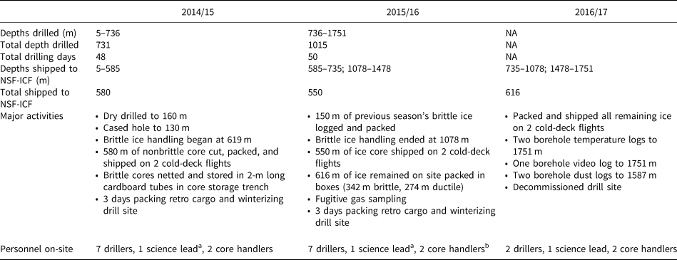
a Two people filled the role by each deploying for half of the season.
b Three core handlers deployed with one staying the entire season and two others splitting the season in half.
The US Intermediate Depth Drill (IDD) system was designed and built by the US Ice Drilling Program (IDP) at the University of Wisconsin–Madison (Johnson and others, Reference Johnson, Shturmakov, Kuhl, Mortensen and Gibson2014). The drill itself, which was designed to collect 98 mm diameter ice cores up to 2 m in length, was based on the proven Danish Hans Tausen drill (Johnsen and others, Reference Johnsen2007). The winch was designed with rated cable capacity of 1700 m. However, for this project, the winch drum was spooled to maximum capacity with 1900 m of cable, making it possible to reach the 1751 m final depth.
Since completion of the SPICEcore project, IDP has been developing a suite of drills that are based on the same sonde design but with various features based on hole depth. The differences include the various length of core barrels and instrument packages. This suite of drills has been given the base name of Foro, which is a Latin word meaning to bore or make a hole. To uniquely identify each system, a number is added after the word Foro, which corresponds to the depth the system is designed to drill. In the case of the IDD system, the name has been changed to Foro 1650 Drill. However, for the remainder of this paper, we will simply refer to the Foro 1650 Drill as the IDD. In the following sections, we discuss the setup, operation, and performance of the IDD system for the SPICEcore project. Details of how the ice cores were handled, logged and retrograded back to the USA are described in Souney and others (Reference Souney2020).
2. Logistics
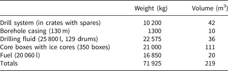
All drilling equipment and supplies for the SPICEcore project were flown from McMurdo Station to the Amundsen-Scott South Pole Station (South Pole Station) on LC-130 aircraft operated by the 109th Airlift Wing unit of the New York Air National Guard. The equipment was then loaded on cargo sleds, which were pulled by heavy-equipment out to the drill site. The entire IDD system packaged for shipping weighed 10.2 t with a volume of 42 m3. Drilling fluid, fuel, borehole casing and ice core boxes added an additional 61.7 t and 177 m−3 (Table 2). Generators and camp facilities are not included in these numbers. Ice cores were boxed and palletized at the drill site and then loaded on a cargo sled for transport back to the South Pole Station. The ice was then flown to McMurdo Station on LC-130 aircraft where it was put into 40-foot freezer shipping containers and loaded on a cargo ship bound for Port Hueneme, California. The final leg of the journey was by truck to the National Science Foundation Ice Core Facility (NSF-ICF), Denver, Colorado.
Weights and cubes for the SPICEcore project
3. Drill site
The SPICEcore drill site was located grid west of the South Pole Station, in what is called the ‘Dark Sector’, with the borehole located at 89.99°S, 98.16°W. Details of the site selection process are described in Casey and others (Reference Casey2014). Altitude at the South Pole is 2835 m with air temperatures generally ranging from −38° to −25 °C during the project, which ran from late-November to the last week of next January each year. A 2.7 km-long groomed and flagged snow road ran between the drill site and the South Pole Station. This close proximity to the South Pole made it possible for the drill team to live at the South Pole Station and commute to and from the drill site via a wheeled van, snowmobile, or even walking or skiing. This also made it possible for the South Pole Station to provide all logistical and heavy-equipment needs, thus not requiring a stand-alone deep field camp to be established.
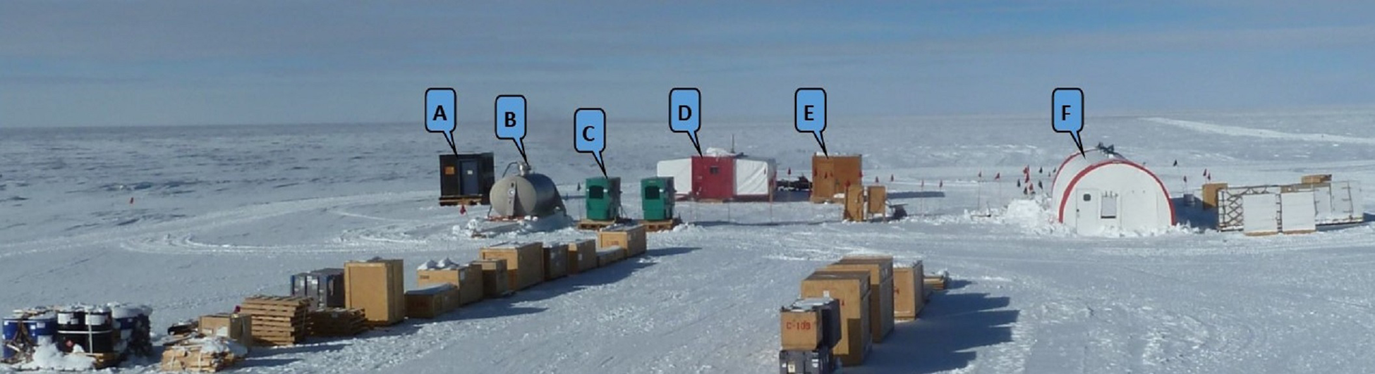
The drilling tent and all equipment contained within it were deployed as part of the IDD system. The US Antarctic Program Support Contractor (ASC) provided all of the other required structures and equipment, including the core storage trench materials. Structures and equipment at the drill site included the drill tent with connected core storage trench, hut dedicated to drying and storing clothing exposed to drilling fluid, warming hut with workspace, outhouse, primary and backup 50 kW generators, and a fuel tank (Fig. 1).
SPICEcore drill site. (a) Outhouse. (b) Fuel tank. (c) 50 kW generators. (d) Warming hut with the workspace. (e) Clothing changing and drying hut. (f) Drill tent. To the right of the drill tent are pallets of empty core boxes. In the foreground are shipping crates for the drill system along with a pallet of drilling fluid in the lower-left corner.
4. Drill setup
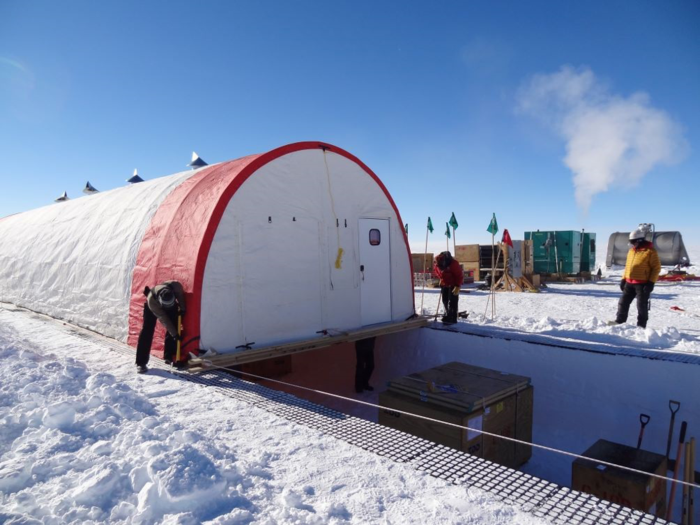
During the 2013/14 season and in preparation for the SPICEcore project, ASC excavated, backfilled, and compacted a 91 m × 91 m × 1.5 m deep pad centered on the borehole location. The increased snow density reduced the settling of the drill system and increased the strength of the drill trench walls. Installation of the drill system began in November 2014. Polyethylene grid tiles were laid in two rows to mark the sides of the trench and provide a footing for the tent. A Caterpillar D8 bulldozer was used to excavate the 18.2 m long × 4.6 m wide × 1.4 m deep trench in the snow surface. Heavy pieces of the drill system were placed in the trench using a track loader before building the wooden end walls of the trench and filling in the ramps. Off one end of the trench, a 6.4 m × 4.6 m underground core storage trench was excavated to a depth of 3 m and covered with a wood deck. A stairway connected the drill trench to the lower core storage area. While the core storage trench was being completed, the drill tent was built off the opposite end of the drill trench. The assembled tent was slid into place over the trench using a tractor-mounted winch. It was determined to be easier and safer to construct the tent on level ground and slide it over the trench rather than build it over the trench (Fig. 2).
IDD tent being pulled into place over the drill trench.
The IDD drill tent measured 19.5 m long × 4.9 m wide × 3.3 m high and was custom-manufactured by WeatherPort Shelter Systems. The outer shell was a PVC-impregnated polyester-cotton canvas that is pliable to −40 °C and is cold crack rated to −80 °C. The shell was tensioned over the steel frame that was specifically designed to withstand 33 m s−1 winds and a 269 kg m−2 snow load. Each end of the tent had a hard-sided entry door along with a 1.2 m wide double-zippered cargo door. Also, between the doors on each end was a screened panel (to keep out blowing snow) for ventilation with canvas winter cover. Along the ridgeline of the tent were four 30 cm diameter openings with powered fans and wind-directional chimney caps to remove warm air at the ceiling and provide ventilation. Once the tent was in place over the trench, the drill trench was weathertight and drill assembly began. A wood footing, which was designed to exert a snow load of no more than 0.2 kg cm−2, was laid for the winch and tower base assembly. A 5.4 m long × 0.8 m wide × 3.6 m deep slot was cut into the trench floor for the drill tower to tilt vertically. A low-temperature liner material, 8228 ORLTA by Seaman Corporation (commonly used to make fuel bladders and tank liners), covered the end wall and bottom of the slot to collect drilling fluid and funnel it back into a stainless steel catch basin that was attached to the top of the borehole casing. A ladder fastened to the sidewall of the slot next to the tower provided access to the slot for maintenance. A fiberglass handrail with toe-kick surrounded the drill slot for safety. In line with the slot was the chips bin, which was used to collect drilling fluid and cuttings as the drill was serviced after a drilling run. Following in line was the core barrel pull-out table, which supports and aligns the core barrel and hollow shaft with the drill when they were being removed and reinserted.
Located to one side of the winch and tower was the 1.5 m wide × 2.4 m long drill control room (Fig. 3). It was an insulated fabric structure with similar construction and materials as the larger drill tent. It had one hard-sided entry door and windows on the side and end wall opposite the door to provide visibility to the activity going on inside the drill tent. A 3 kW wall-mounted heater and a heat recovery ventilation system kept the control room warm and well ventilated.
Drill setup layout: (a) Winch. (b) Drill and tower in the horizontal position. (c) Barrel pull-out table. (d) Glove dryer. (e) Control room with roof-mounted heat recovery system. (f) Control box for winch, tower and drill. (g) Power distribution panels and transformer. (h) Centrifuge with ventilation system. (i) Work bench. (j) Borehole casing. (k) Vacuum system for use with the cable cleaner and for removing drilling fluid from the cores. (l) Drill slot ventilation system. (m) Core processing line. (n) Core storage trench with core storage shelving. (o) Lift for moving full core boxes to the surface where they are put onto pallets for shipping.
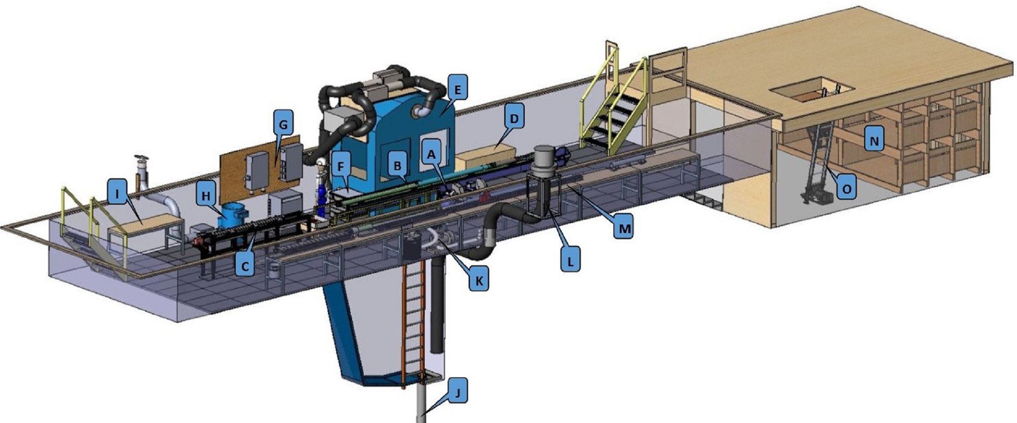
Located outside the door of the control room was a heated and ventilated warming box for storing and drying gloves between drill runs. To the opposite end of the control room was the control box, which contained the drives for the winch and tower and power supply for the drill sonde. The control console for running the winch and drill were located inside the control room. Next in line was the wall-mounted power distribution system, which supplied the drill tent with 480/208 VAC three-phase and 208/120 VAC single-phase power. All connections on the power system were connectorized, making installation and packing a quick and easy task. Following the power system was a 15.5 L capacity centrifuge that was used for separating ice cuttings from the drilling fluid. The fluid recovery tank for the centrifuge included a secondary filter and was plumbed via a hose directly to the borehole for return of the recovered fluid. Last in line on that side of the tent was a workbench with tool storage area. Running the length of the drill tent on the opposite side from the control room was a 12.8 m long core processing line that was designed to process the 2 m long ice cores. The system consisted of four 2 m long adjustable rail assemblies mounted on a series of seven rigidly-connected workbenches. The aluminum rail assemblies were fully adjustable so they could be aligned to each other to minimize stress on the core as it was pushed out of the core barrel and onto the core tray, dried, logged, cut into 1 m lengths, and packed. Further details about the core processing line are described in Souney and others (Reference Souney2020). Site construction, including all snow excavation and drill assembly, was completed over a period of 12 days by the 11 member SPICEcore team along with additional support, as needed, by equipment operators, carpenters, and electricians provided by ASC.
5. Drill operations
Two 10-hour shifts per day were run during the first season and three 8-hour shifts per day the second season, working 6 days per week with Sundays off. For the first season, there were three drillers and one core handler per shift. For the second season, shifts were reduced to two drillers and one core handler. In addition to the drillers and core handlers, there was a lead scientist and lead driller who oversaw and helped out with day-to-day operations, maintained communications with the South Pole station, and were available to function as a driller in the event of an illness or injury. The main reasons for going from two shifts to three shifts was to increase from 20 to 24-hour operations, reduce the exposure time of operators to the drilling fluid and reduce operator fatigue due to the altitude and cold.
The ambient temperature inside the tent was maintained at or below −20 °C to preserve the integrity of the gas record in the ice cores. The temperature was regulated primarily by using four powered roof ventilators to remove heat build-up from the tent ceiling. A powered ventilator for the drill slot and a second ventilator next to the chip processing centrifuge, whose primary function was to maintain air quality, also aided with cooling. The combination of these ventilators provided ~22 air exchanges per hour. The screened panels on either end wall of the tent provided makeup air while keeping out blowing snow so the doors could remain closed on windy days.
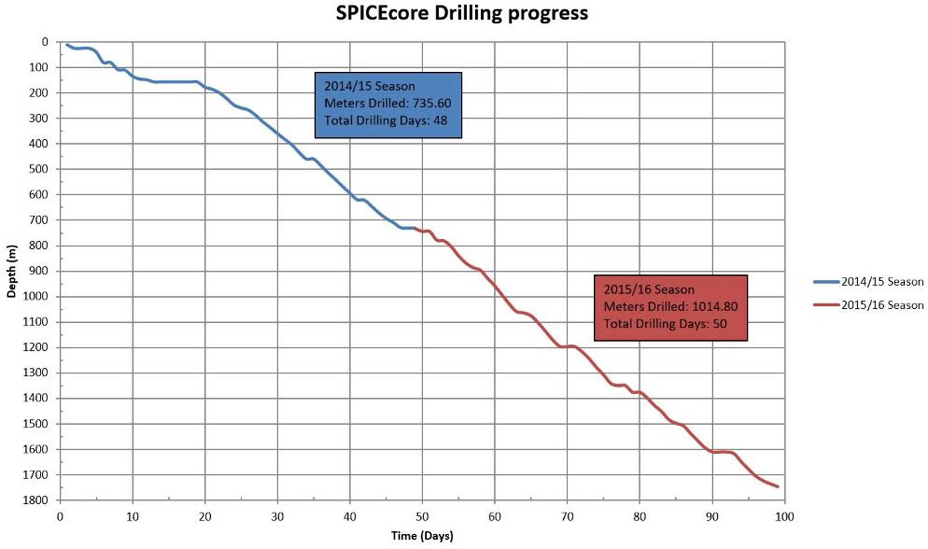
In total, it took 98 days over two seasons to reach 1751 meters. This included 48 operational days during the 2014/15 season, drilling from 5 m to 736 m and 50 days during the 2015/16 season, drilling from 736 m to 1751 m. The 98 days is the sum of the days beginning with the first day of drilling through the last day of drilling each season, which includes all days off and holidays, reaming and casing the pilot hole, chips bailing and downtime for repairs. This works out to an overall average drilling rate of 18 m d–1 for the entire project or 25 m d–1 if days off and time spent bailing are excluded (Fig. 4).
SPICEcore drilling progress graph showing depth verses days. Notes about horizontal sections of the curve: 20 m, diagnosing control system electronics issues; 155 m, reaming and casing the pilot hole, Christmas break; 460 m, generator and control system electronics issues and chips bailing; 620 m, first shift off, chips bailing on second shift; 780 m, drill motor and controls system electronics issues; 1060 m, diagnosing shorted conductor in the winch cable; 1200 m, Christmas break; 1340 m, New Year's break; 1375 m, installed new winch cable; 1610 m, control system electronics failures, caused by lose ground wire on generator.
5.1 Drilling procedure
A drill run began with tilting the tower and drill from the horizontal to the vertical position. This was done with a handheld pendent, which was operated by the driller working outside the control room after they verified all were clear and double-checked all of the connections on the drill were secure (Fig. 5).
The driller in the foreground begins to tilt the tower as the other driller does one final inspection of the cutter head.
The pendent controller provided fully proportional speed control of an electric linear actuator that tilted the tower. Next, the driller in the control room ran the winch to verify the drill was at the home position by driving the sonde upwards to make contact with a switch located on the tower, just below the crown sheave. Zero depth was reset on the control screen and a new drill run was inserted into the electronic logbook. The hole cover was opened and the drill was lowered at 0.15 m s−1 while it was on the tower and entering the casing. Once the drill was fully inside the casing, the hole cover was closed and the descent speed was increased to 0.5 m s−1. Next, the driller watched the screen for a quick decrease in line tension, which indicated the drill was entering the drilling fluid, and clicked a button to record the fluid level. With the drill in fluid, the speed was again increased. Because the IDD did not have a weight on bit sensor built into the drill, the control system computer calculated the estimated drill weight (EDW) based on the payout, fluid level and cable load measured by the load pin in the crown sheave. Payout speed was increased manually based on EDW, not allowing the EDW to go below 100 N. This permitted a maximum safe descent speed of between 0.7 and 1.0 m s−1. Descent speed was slowly decreased starting ~20 m above the hole bottom and was further decreased to 0.03 m s−1 at 1 m above the borehole bottom. The payout was stopped at 20 cm above the bottom to start coring for normal drilling runs. The drill motor was then turned on in forward rotation with a rotational speed of ~60 rpm. The drill was then lowered at ~3.0 mm s−1 until it started coring, as indicated by an increase in drill motor current. The core length delta depth zero was then reset and the penetration rate adjusted to maintain as little weight on a bit as possible without the cutters disengaging from the ice. Penetration rates were generally between 2 and 3 mm s−1 for most drill runs. A normal drill run ended when a full 2 m core was drilled or the cutter current started to climb, indicating the chips chamber was full. After payout was stopped, the drill was kept running for ~20 s, until the cutter current dropped back down, indicating it was no longer cutting (Fig. 6).
(a) The drillers are keeping a close eye on drill parameters as they collect a core. (b) Drill control screen from run 749 at 1250 m depth. (A) Drill motor is turned on, yellow line. Drill motor current increases and then stabilizes. (B) Drill motor current increases when the cutters engage the ice. (C) End of coring, payout has stopped and the drill motor current soon drops. (D) Cable tension, green line. (E) Weight on bit, blue line. (F) Payout feed rate, purple line.
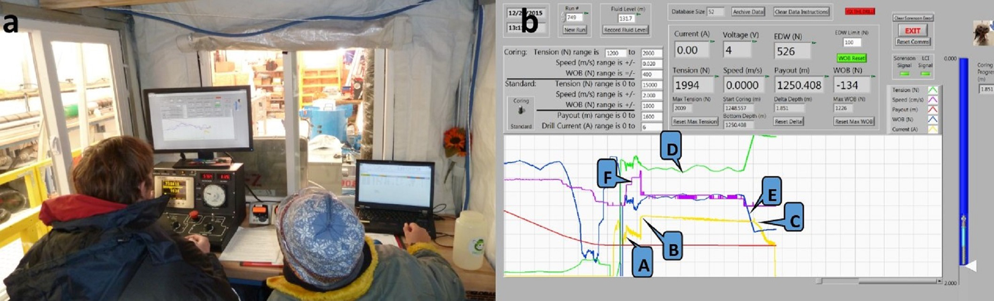
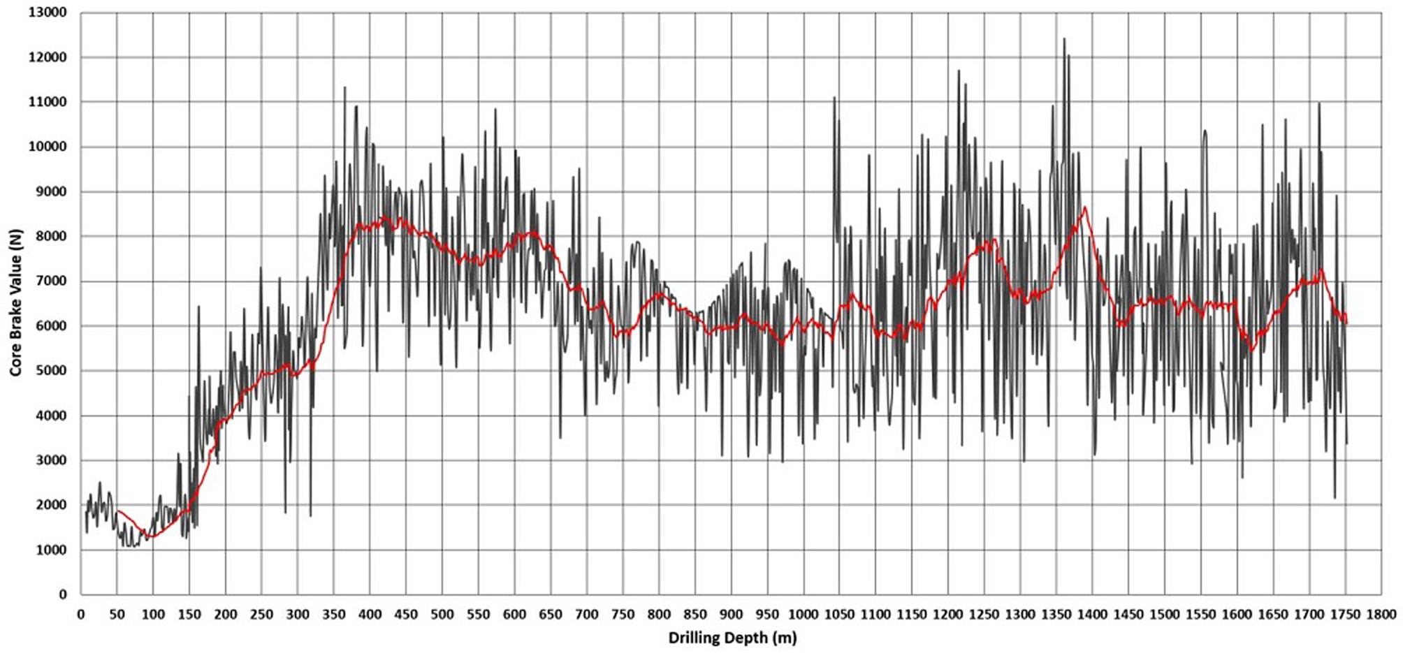
During this time, data were entered into the logbook for core length, penetration rate and drill motor current. The drill motor was then turned off and the core break was initiated by quickly accelerating the winch in ascent mode to ~0.5 m s−1. The computer automatically captured and displayed the core break load, which the driller then entered into the logbook (Fig. 7).
Core break values corrected for cable weight and load pin nonlinearity. The truncated peak values between 750 m and 1040 m depth were due to a configuration error of the line control meter.
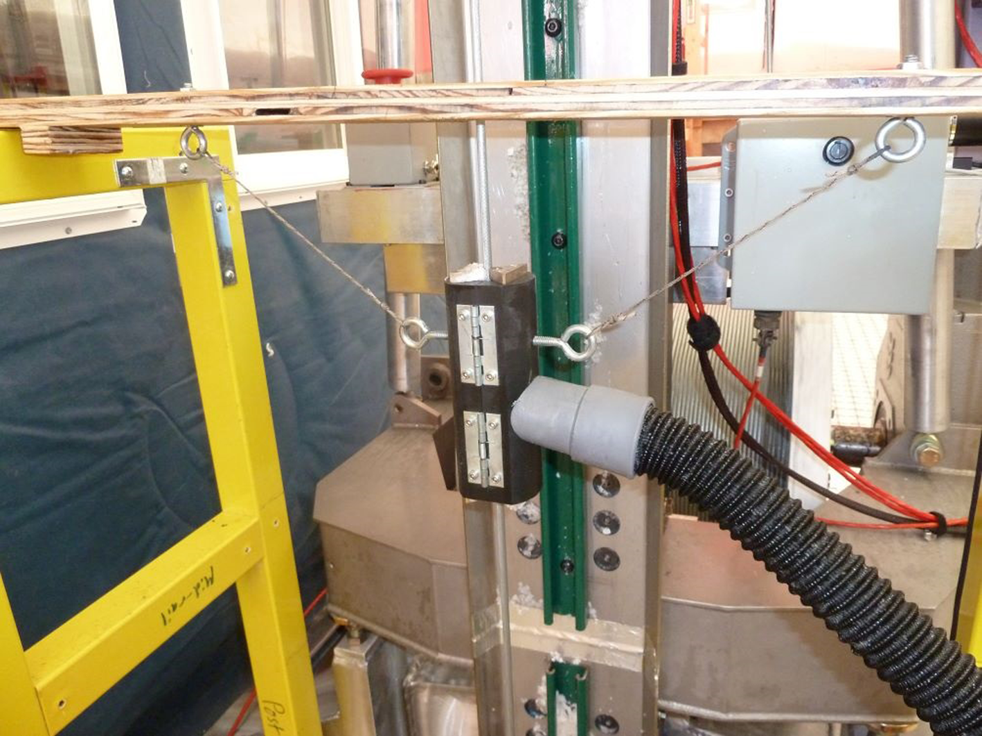
After the core break, a cable cleaner, which was connected to a vacuum hose, was attached to the drill cable to remove drilling fluid coming up on the cable (Fig. 8). This device was very effective and left the cable nearly dry while recovering ~30 liters of drilling fluid off 1700 m of cable traveling at up to 1.5 m s1. For the ascent back to the surface, the line speed was increased up to the max speed of the winch, which is ~1.5 m s−1. About 10 m before reaching the recorded fluid level, winch speed was decreased to 0.5 m s−1 and further to 0.3 m s−1 when the drill exited the fluid. Winch speed was again set to 0.15 m s−1 as the drill exited the casing and traversed up the tower. When the drill reached the limit switch, the winch automatically stopped. The winch speed and direction switches were turned off, the hole cover was closed and surface operations began.
Cable cleaner with an attached suction hose for removing drilling fluid from the winch cable.
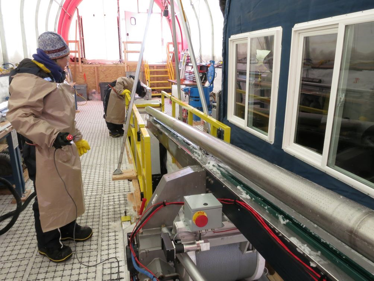
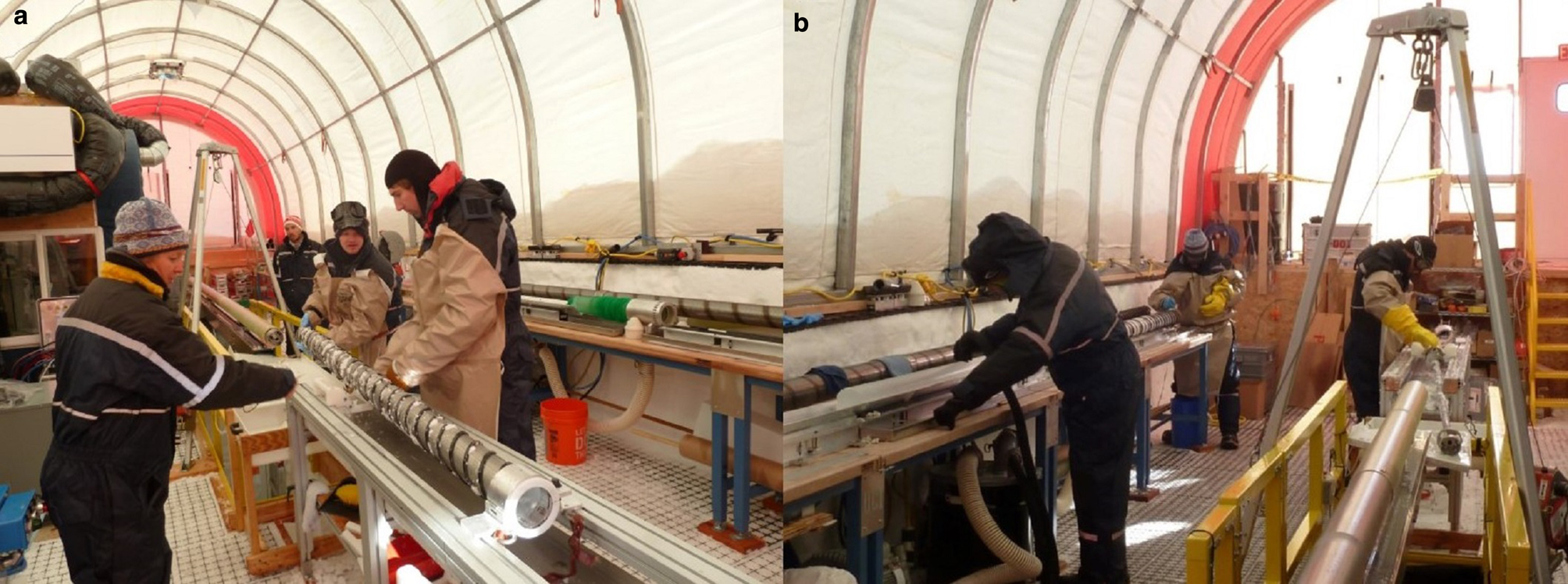
Once the drill and tower were tilted back to horizontal, three locking pins that couple the drive plate of the motor section to the chips chamber hollow shaft were disengaged. A specially designed head clamp was placed over the cutter head, which was used for pulling out the core barrel and hollow shaft assembly, as well as to protect the drillers from the cutters. As the core barrel was pulled from the drill, the head clamp was guided on the rails of the pull-out table to keep the barrel aligned with the drill. The pack of cuttings and drill fluid on the core barrel flights were brushed off into the tub located between the end of the drill and the pull-out table. Most of the time the core barrel and hollow shaft could be pulled by hand; however, if more force was required, a hand-crank winch on the pull-out table could be used. A drip tray, which ran the length of the pull-out table, collected any additional drilling fluid dripping off the core barrel and drained into the tub. When the core barrel was nearly removed from the drill, a second sliding support was added under the barrel on the pull-out table. Once the top of the core barrel came out of the drill it was disconnected from the hollow shaft by depressing three locking pins identical to those that coupled the drive shaft to the motor section. The core barrel was then transferred by hand from the pull-out table to the core processing line. The ice core was then pushed out of the barrel and onto a receiving tray using a push rod. The cutter head was cleaned and the cutters and core dogs were inspected for wear or damage (Fig. 9). Details about how the ice cores were handled, logged, and packed are described in Souney and others (Reference Souney2020).
(a) The core barrel has been disconnected from the hollow shaft to move it over to the core processing line. (b) The core handler in the blue suit on the left uses a vacuum to remove drilling fluid from a core while the driller in the back cleans the core barrel and cutter head. The other driller on the right cleans the hollow shaft.
After the core barrel was transferred to the core processing line, the hollow shaft was pulled from the drill to empty the cuttings that were collected during the drill run. The slurry of cuttings and drilling fluid was collected in the tub as the shaft was pulled out onto the pull-out table. Once removed it was further cleaned before being reinstalled. The core barrel was then brought back over to the pull-out table, coupled to the hollow shaft, and installed back into the drill. Finally, the locking pins on the drive shaft to motor section coupling were locked into place. After a final inspection, the tower was tilted back to vertical, and the next drill run began.
6. Power system
Electrical power for the drill site was provided by a 50 kW diesel generator. A second identical generator could be quickly brought online to minimize downtime due to generator failure or maintenance. Actual usable power from the generator was de-rated to ~40 kW due to the 2835 m altitude at the site. Peak power consumption for the drill site (drill system and electric heat in the other outbuildings) was ~33 kW with the winch under full load. Power from the generator was fed into a distribution panel outside the drill tent, which supplied power to each of the buildings and to the drill system power distribution panels located inside the drill tent.
7. Pilot hole operations
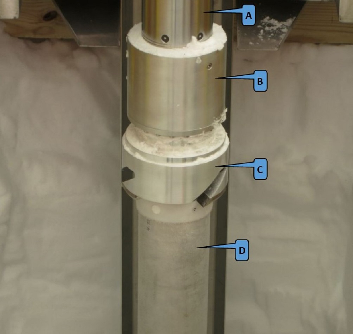
The IDD was specifically designed for versatility; with the ability to perform both dry and wet drilling operations, run borehole reamers, and the winch and tower can be used to set the casing (Johnson and others, Reference Johnson, Shturmakov, Kuhl, Mortensen and Gibson2014). For dry drilling, the IDD was configured with the 2 m long core barrel and chips chamber tube and the hollow shaft without vent holes. Two boosters were run on the hollow shaft, one right above the core barrel and a second spaced ~20 cm further up the hollow shaft. Drilling of the 126 mm diameter pilot hole began at the bottom of the drill slot, which was 5 m below the snow surface and continued to a final depth of 160 m. The core barrel and chips chamber were then replaced with a 178 mm diameter reamer, which was run to a depth of 135 m (Fig. 10).
(a) Drill motor section. (b) Coupler with slewing bearing. (c) 135 mm diameter reamer head. (d) Chip collection tube.
Next, a 229 mm reamer was run to a depth of 130 m to ensure the casing would extend below the estimated firn pore close-off depth of ~120 m (Battle and others, Reference Battle1996). The drilling and reaming operations took a total of 16 days, which included 4 days addressing electrical and mechanical issues, which are discussed below in the Challenges section.
7.1 Casing
The SPICEcore borehole was cased with DR17 high-density polyethylene pipe. The 219 mm OD × 192 mm ID pipe was supplied in 4.6 m lengths with threaded ends. A casing shoe, which was designed to create a fluid-tight seal between the casing and the ice, was threaded onto the leading end of the casing. The shoe had an O-ring on the leading face and three O-rings spaced 32 mm apart on the outside diameter. The face O-ring provided the initial seal until borehole closure brought the ice in contact with the O-rings on the outside diameter (Fig. 11).
Casing shoe with sealing O-rings (orange bands) attached to the first section of casing.

The threaded seams between casing sections were sealed with a bead of Loctite PL 500 adhesive placed in a groove where the sections threaded together. Casing sections were lowered using the winch cable and a hinged clamshell clamp that installed on the top of each casing section. Once a casing section was lowered, a second clamshell clamp, located at the bottom of the slot, was fastened to the casing to carry the load while the upper clam was removed and another piece of casing was threaded on. Once all of the casing was lowered into the borehole and was sitting on the ledge created by the 229 mm diameter reamer, it was cut flush with the bottom of the slot and a stainless steel drip pan, which created a sump to gather drilling fluid, was sealed to the top of the casing followed by a short collar and hinged hole cover. Openings in the collar, which were covered by a filter screen to keep out debris, allowed drilling fluid to drain from the sum back into the borehole.
8. Wet drilling
Once the casing was installed, drilling fluid was added to the borehole and wet drilling operations began. The drill fluid level was maintained at ~130 m below the surface, which allowed much of the drilling fluid on the drill to drain off before it reached the surface. The drill was configured for wet drilling by changing out the solid chips chamber tube for one with 7200 1.4 mm diameter vent holes and adding a flapper-style check valve above the lower booster on the hollow shaft. Whenever the chips were not compressed into a tight pack, the check valve kept the chip slurry in the chips chamber while the drill was being tripped back to the surface (Fig. 12).
(a) Chips valve housing with an internal booster. (b) Hinged valve plates. (c) Upper booster. (d) Hollow shaft.
The same core barrel that was used for dry drilling was also used for wet drilling. Cutter speed was ~60 rpm with penetration generally between 2 and 3 mm s−1. Fine cuttings were noticed oozing from the vent holes in the chips chamber tube after a drill run (Fig. 13).
Vented chips chamber tube with fine cuttings seeping from the vent holes.
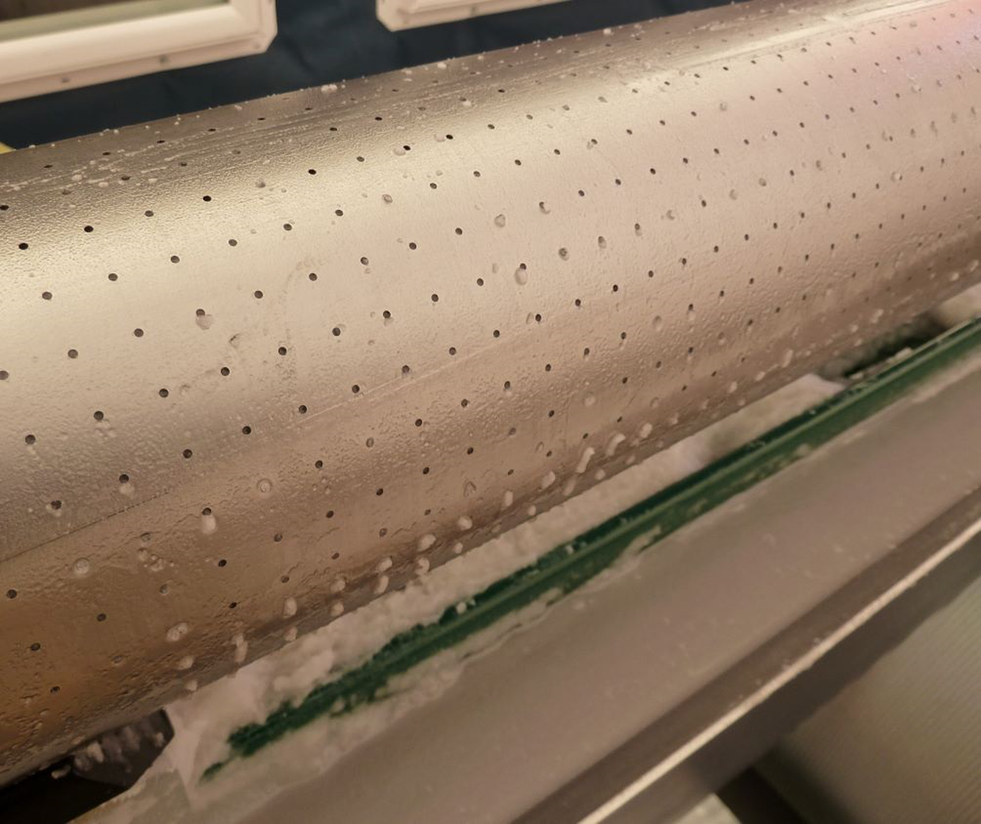
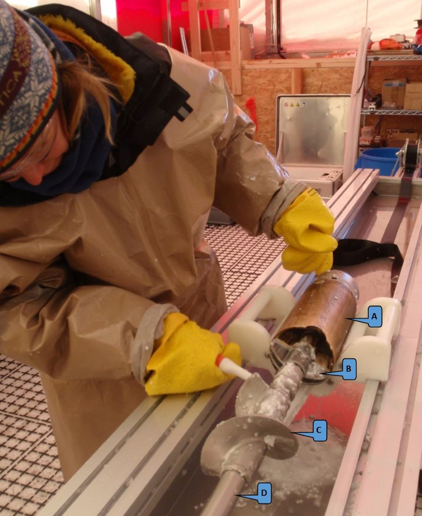
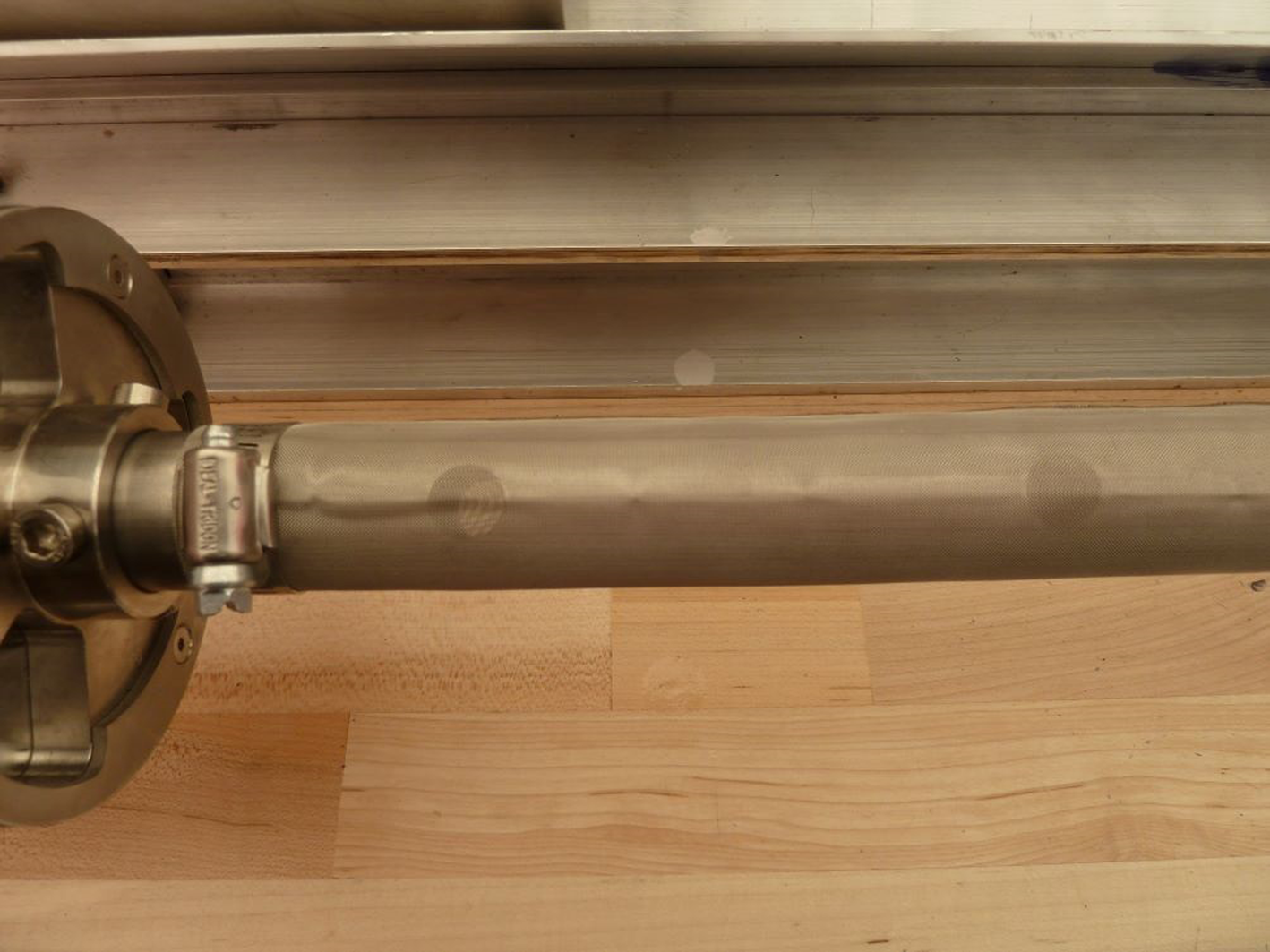
It was calculated that ~12% of the total cuttings created by the drill were being left in the borehole. As drilling progressed, the first season, three to four chip bailing runs had to be completed every day to avoid having problems with penetration and not being able to drill full 2 m long cores. For the second drilling season, a pattern of 80 holes, 12 mm in diameter were drilled through the 2.6 m hollow shaft. A cylindrical 80 mesh filter screen was fitted over the hollow shaft to act as a filter and keep the cuttings in the chips chamber while allowing drilling fluid to pass through the 12 mm diameter holes, up the central bore and out the top of the hollow shaft (Fig. 14).
Close-up view of the hollow shaft with 12 mm diameter vent holes covered by an 80-mesh filter screen.
The modified hollow shaft was paired with a nonvented chips chamber tube. This configuration performed much better, reducing the cuttings loss to ~7% and only requiring bailing operations to be conducted on three occasions throughout the season.
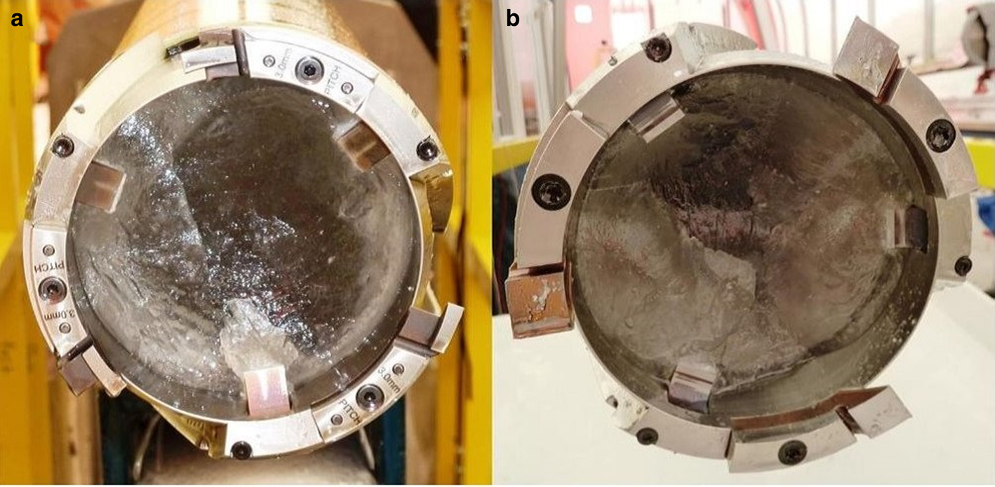
All wet drilling was done with 126 mm diameter cutters. Standard full-kerf cutters were initially used, however, the ice at the South Pole was found to be harder to cut than ice at other sites IDP has drilled, requiring finer cutting pitches to be run in order to keep the load on the drill motor within an acceptable range (Fig. 15b). The fine pitch also led to smaller chips and poor chip transport. In an effort to reduce the cutter torque and create larger chips, step cutters were introduced (Fig. 15a).
(a) Step cutters. (b) Standard full-kerf cutters.
Drill motor current was noticeably lower and drill performance improved due to the larger size chips created by the step cutters. As wet drilling progressed, it was also found the cutters were dulling faster than expected and notching of the cutting edges and chipping of the corners on both the cutters and core dogs was observed. In preparation for the second drilling season, the cutters and core dogs, which were fabricated from A2 tool steel hardened to 58–60 HRC, underwent a cryogenic treatment followed by a second tempering to improve the toughness of the steel. This process effectively eliminated the notching and chipping.
Another challenge appeared as the borehole depth approached 900 m. The step cutters periodically would not penetrate at the start of the drill run, often causing the drill run to be aborted. However, every time this happened, the next run could be successfully completed with the full-kerf cutters. Therefore, a majority of the drilling performed deeper than 900 m had to be done with the full-kerf cutters. Periodically, the step cutters were tried again and would occasionally penetrate fine for a few runs, but during others, they would not penetrate at all.
9. Chips handling
All cuttings and drilling fluid that were removed from the chips chamber were collected in a shallow tub that was on a stand with a runner sled type base so it could be easily slid across the floor. After the drill had been serviced and sent back downhole, the tub was slid over to the centrifuge and the chips slurry was transferred with a hand scoop into the fabric lined centrifuge basket. The centrifuge cycle would run for ~8 min and was effective at removing ~85% of the fluid from the cuttings. Drilling fluid recovered by the centrifuge drained into a tank where it ran through a filter before draining back to the borehole through a hose that was plumbed between the tank and the borehole. If the chip slurry contained too much drilling fluid, the centrifuge would become out of balance and shut down. This was resolved by taking batches of chip slurry that had a high liquid content and running them through a filter to drain off most of the drilling fluid before placing them in the centrifuge.
10. Drilling fluid
The drilling fluid chosen for the SPICEcore project was ESTISOLTM 140. The decision to use this fluid was based on lab testing and field trials conducted by the Centre for Ice and Climate, Niels Bohr Institute, University of Copenhagen, Denmark (Sheldon and others, Reference Sheldon, Popp, Hansen and Steffensen2014). The average 15 m depth firn air temperature at the South Pole is −51 °C (Severinghaus and others, Reference Severinghaus, Grachev and Battle2001) and the density of ESTISOLTM 140 is 922.0 kg m−3 at −40 °C to 930.4 kg m−3 at −50 °C (Talalay and others, Reference Talalay2014), making it a nearly ideal single component fluid to pressure balance the SPICEcore borehole. The kinematic viscosity of ESTISOLTM 140 is 12.2–25.6 mm2 s−1 between −40° and −50° C (Talalay and others, Reference Talalay2014), which made it possible for the 118 mm diameter IDD to reach a descent speed of up to 1 m s−1 in a 126 mm diameter borehole. ESTISOLTM 140 is also not classified as a hazardous or toxic material, which minimized shipping and handling restrictions. Despite a number of favorable attributes, ESTISOLTM 140 reacts with many elastomers and plastic materials, limiting the types of seals, wire jacket materials, equipment containing plastic parts, and selection of personal protective equipment (PPE) that can be used in and around it. ESTISOLTM 140 also has a strong odor, particularly at room temperature, from which some people experience negative side effects.
Drilling fluid was shipped to the drill site in steel drums. During the drilling operations, pallets of drums were staged along one side of the drill tent. The fluid was transferred from the drums into the drill tent with an electric drum pump. The hose from the pump was routed under the floor to the bottom of the drill slot where it connected to a fitting at the top of the borehole casing. A total of 25.8 m3, or 129 drums, of ESTISOLTM 140 were used for the SPICEcore project. The total fluid loss was 15%, a majority of which was due to the inefficiency of the centrifuge process, with the remainder due to fluid left on the cores, loss during drilling operations and evaporation.
11. Working with ESTISOLTM 140
To minimize operator exposure to ESTISOLTM 140 and to keep insulating layers dry, a variety of PPE and operational mitigations were implemented. When handling the drill and working directly with the drilling fluid, DuPont™ Tychem® 5000 CPF 3 aprons with arms were worn over one-piece insulated waterproof coveralls. This material was one of the few materials found that was completely unaffected by ESTISOLTM 140 and maintained decent flexibility at −40 °C. Dailove 102 series thermal gloves were the preferred insulated glove for general work and deteriorated much slower than other glove options. If a task required finer dexterity, polyethylene food service gloves or nitrile gloves were worn under fabric mechanics gloves. Baffin Derrick-model safety toe boots performed well in both the cold and in contact with the drilling fluid. Safety glasses or goggles were worn at all times when working with the drilling fluid. The only symptoms experienced with ESTISOLTM 140 coming directly in contact with skin were dryness and mild irritation in isolated cases. The larger issues experienced with using ESTISOLTM 140 were drillers reporting having headaches, lightheadedness, appetite changes, loss of sense of smell and irritation of the nose and eyes. Their symptoms persisted despite the ventilation in the drill tent providing 22 air exchanges per hour and a down-draft ventilation system in the heated control room providing 53 air exchanges per hour. Aprons and gloves were kept outside the heated control room to minimize drill fluid in this space. Results from air monitoring conducted with a handheld photoionization detector (PID) in both the drill tent and control room showed concentration levels did not exceed 7.0 ppm for 15 min measurements and 1.8 ppm for an 8-hour measurement, which is well below the published Derived No Effect Level (DNEL) of 20.4 ppm for acute exposure and 10.2 ppm for long-term exposure. All outer layers of clothing worn while working, including boots, were kept at the drill site and dried and stored in a heated changing building next to the drill tent. This was effective at minimizing the amount of contaminated clothing brought back to the South Pole Station and therefore the smell of ESTISOLTM 140 in common areas and berthing spaces.
12. Challenges
Even with well designed and tested equipment, there will always be challenges that arise and must be dealt with in the field. The difference between a successful or failed season often comes down to having the right pieces of spare equipment, the correct tools and having the right mix of skill sets within the crew. The following paragraphs discuss the other major challenges encountered during the SPICEcore project that have not already been presented in previous sections of this paper.
Soon after the drill was commissioned at the start of the first season, periodic failure was experienced with circuit boards in both the control box and the operator's console. The issue was eventually traced back to the neutral and ground not being bonded together in the generator disconnect, as had been done on the generators used for the drill test previously conducted in Greenland. This can be damaging to electronic devices since without the neutral and ground bonded, the neutral line is left floating and therefore it can be at a higher voltage potential than the ground.
During the second season, drill motors periodically failed. Sometimes, they would run fine for a week or more and then, seemingly randomly, they could not even complete one drill run before the brush holders would melt (Fig. 16).
Drill motor. Arrows point to areas where the brush holder overheated and melted.

The downhole electronics package was not designed to provide feedback to the surface for motor voltage, current, or rpm, however, from the operator's perspective, parameters were within safe operating ranges. The drill was kept running through the duration of the season by replacing and rebuilding the motors with spare parts as they failed. Lab testing after the season revealed that under load, the drill power supply (DPS), which is located in the motor section and was designed to provide current limiting and variable voltage up to a set limit (for variable motor speed) and then switch to a constant voltage output mode, was not current limiting properly. Therefore, when the operator thought the drill motor was running at maximum-rated voltage and speed, the DPS could actually be driving the motor with a much lower voltage and current well above its rated value. A new sonde control system is currently in development which will provide feedback on motor voltage, current and speed to the operator in addition to inclination, orientation, temperature and pressure data. As part of the electronics upgrade, the drill motor is also being changed from a brushed to a brushless design.
FEP (Fluorinated Ethylene Propylene) wire insulation was specified for the conductors in the winch cable due to the material's excellent chemical resistance, dielectric strength and low-temperature performance. However, during the second season, the material was found to be susceptible to cold flow under pressure, which caused a short between the wires and armor jacket during drilling operations. The short occurred at a point where the cable wraps cross over each other on the winch drum, which creates a point of localized loading. A spare 1922 m winch cable, along with a cable spooler and cable tensioner, were on site, so the drill team was able to efficiently remove the damaged cable from the spool and properly install the new cable under the correct tension profile (Fig. 17).
Spooling and tensioning a new drill cable onto the IDD winch. (a) Spool of new cable. (b) Cable tensioner mounted on the drill tower. (c) The load cell and encoder on the top sheave are used to monitor tension and measure cable length as it is spooled onto the (d) winch spool.

Installation of the new cable was going smoothly until the cable caught on a screw head protruding from the inner flange of the wood spool shipped by the manufacturer. The screw head, which had been covered by the previous wrap layer, severed one armor wire on the cable jacket and damaged a couple of other armor wires as the cable was coming off the spool. Fortunately, the team was able to repair the damage and continue using the cable by restraining the broken armor wire through a process called ‘shimming’. At the recommendation of the cable manufacturer, replacement cables were purchased with ETFE (Ethylene Tetrafluoroethylene) wire insulation. The main reason to switch to ETFE is it has much less tendency to creep under pressure than FEP in this demanding application. This insulation material also has good chemical resistance and low temperature performance, however, ETFE does not meet the dielectric strength of FEP. The new 1650 m cable with ETFE insulation was installed on the winch after the completion of the SPICEcore project and is awaiting the next drilling project for field testing.
The fleet angle of the winch cable between the winch drum and the crown sheave was found to influence the load cell reading. As the cable angle increased toward one side of the winch drum the load reading would decrease and as it increased toward the other side it would increase, causing up to a 16% error. It was determined this was due to the full-bridge configuration of the strain gauges in the load pin being sensitive to torque loads. The load pin has since been changed to one with a parallel bridge strain gauge design, which reduced the error to ~1%.
13. Winterizing and packing
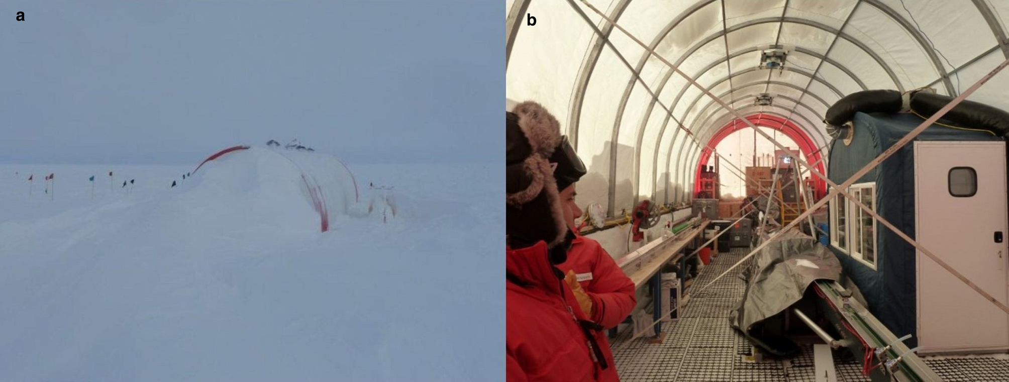
The drill tent and the entire drill system remained set-up over two winters. Temperature-sensitive equipment, such as electronic components, were removed from the drill tent and stored inside the South Pole Station in heated storage. Any equipment that required maintenance or repair, such as drill components and the control system electronics were shipped back to the IDP facilities at the University of Wisconsin-Madison between seasons. To ensure the tent was secure for the winter, internal tie-downs were added between the tent frame and snow anchors. The doors were also secured to make sure they would not blow open during a winter storm. The other structures and cargo were moved downwind from the drill site and put up on berms to prevent drifting. The drill tent did not sustain any damage over either of the two winters and very little snow managed to enter the structure. Drifting around the tent was easily cleared with heavy equipment at the start of each season (Fig. 18). Four days were spent at the end of each of the first two seasons winterizing the drill site and transitioning the drill team back to a single day shift.
(a) View of the downwind end of the drill tent after the winter. (b) Inside of the drill tent after the winter.
Following the completion of drilling, take-down and packing of portions of the drill system began during the winterizing period at the end of the second season. The chip processing and fluid handling systems were disassembled and packed. During this period, the casing was also extended up to the surface and the drill slot was filled in. The winch, upper portion of the drill tower and control room remained in place for use with logging operations along with the core processing line, which was required for cutting and packing the stored 2 m long lengths of brittle ice.
For the third and final season, which took place during a 3-week period between late November and mid-December 2016, a team of two drillers, two core handlers and one science lead deployed to finish logging and packing the ice cores and complete packing of the drill system and drill site closeout. A sixth person joined the team for part of the time to lead borehole logging operations, which included two temperature logs, one video log and two dust logs of the borehole. Final takedown, packing and site cleanup was completed over a period of 7 days, part of which overlapped the end of borehole logging. By the time the team departed the South Pole on 13 December 2016 all that remained at the drill site was the casing extending ~1.2 m above the snow surface.
14. Conclusion
The SPICEcore project was a very successful ice coring effort that recovered a 1751 m deep high-quality ice core near the South Pole over two austral summer seasons. The newly-developed IDD proved to be a well-designed and efficient system that performed well overall in the harsh conditions of the polar plateau. Challenges drilling the hard ice at this site along with complications of electrical and mechanical components, which are not uncommon working in such environments and with a new drill system, were handled in stride by the well-trained and equipped drilling team. This project was IDP's first experience using ESTISOLTM 140 drilling fluid. It worked well from a drilling standpoint but was also challenging to work with because it aggressively attacks many types of plastic materials and several operators experienced negative side effects due to the vapor. Despite the various challenges, the entire project was completed within the originally planned schedule and exceeded the original depth goal by 251 m. With periodic maintenance to keep the casing extended above the surface, the SPICEcore borehole will remain accessible for years to come and will be a valuable asset for future bore logging interests at the South Pole.
Acknowledgements
The US Ice Drilling Program would like to thank the US NSF Office of Polar Programs for making this project possible; The University of Wisconsin – Madison, particularly the Space Science and Engineering Center for program support; the Antarctic Support Contract for operational and logistics support in Antarctica; the 109th New York Air National Guard for airlift support in Antarctica; the USAP science cargo team for their cargo support; and the entire SPICEcore project field team for their dedication and perseverance in drilling this ice core. This work was supported by NSF Cooperative Agreements OPP-0841135 and OPP-1327315.


 Open access