


I. INTRODUCTION
Microwave ablation (MWA) is a promising technique for the minimally invasive treatment of primary tumors. An interstitial antenna delivers energy that heats up the cells, leading to coagulative necrosis of the malignant tumor (e.g. [Reference Carrafiello1]). MWA has been shown to be an effective clinical tool for treating liver tumors (e.g. [Reference Martin, Scoggins and McMasters2]). There is a growing interest in MWA for treating other types of cancer, including breast tumors. This interest is motivated in part by the desire to minimize the “collateral damage” of conventional breast cancer treatments [Reference Love3].
The success of MWA depends in part on the ability to accurately monitor the evolution of the ablation zone during the therapy procedure. Magnetic resonance imaging (MRI) [Reference Morikawa, Naka, Murayama, Kurumi, Tani, Haque, Kahn and Busse4] and ultrasound imaging [Reference Yang, Wu, Bai and Gao5] have been explored as MWA monitoring modalities. However, MRI has several drawbacks in terms of cost and concerns about heating MR contrast agents [Reference Merckel6]. Also, the ultrasound imaging technique suffers from image distortion during thermal ablation due to the formation of microbubbles [Reference Correa-Gallego, Karkar, Monette, Ezell, Jarnagin and Kingham7], as well as limited echogenic contrast between ablated and non-ablated tissue [Reference Yang8]. Microwave imaging is a promising alternative for several reasons. It is portable and low cost. The data acquisition scheme can use the MWA antenna as a transmitter and a number of external antennas as the receivers. Furthermore, the microwave-frequency dielectric properties of tissue are sensitive to the temperature and physiological state of the tissue. Significant changes in the microwave-frequency dielectric properties of bovine liver tissue have been observed during MWA and as a function of temperature [Reference Stauffer, Rossetto, Prakash, Neuman and Lee9–Reference Lazebnik, Converse, Booske and Hagness11]. Similarly large contrasts between ablated and healthy tissues have been observed in a recent breast tissue study [Reference Mays12]. The dielectric properties contrast between non-ablated and ablated tissues causes a signal reflection at the ablation boundary, and making it possible to monitor the ablation zone by exploiting microwave forward or backscatter signals.
MWA monitoring using microwave tomographic imaging has been explored for liver tissue ablation [Reference Bucci, Cavagnaro, Crocco, Lopresto and Scapaticci13] under assumptions that the dielectric properties distribution of the tissue is fairly homogeneous – a reasonable assumption for the liver. Breast tissue has a heterogeneous dielectric structure, in contrast to liver tissue, and this precludes the use of monitoring approaches based on beamforming, since they highly depend on the assumed propagation model. Microwave tomographic techniques have also been proposed for monitoring MWA of breast tumors [Reference Neira, Van Veen and Hagness14]. The computational cost can be reduced through the introduction of simplifying assumptions in the inverse scattering algorithm (e.g. [Reference Haynes, Stang and Moghaddam15]); these assumptions tend to limit the accuracy, however. A persisting challenge has been simultaneously achieving efficient and accurate imaging algorithms for real-time monitoring.
This paper presents a comprehensive theoretical investigation of a novel real-time imaging algorithm for MWA monitoring [Reference Kidera, Neira, Van Veen and Hagness16], which exploits the time difference of arrival (TDOA) between transmitted signals recorded before and at a specific time point during the ablation. Our proposed algorithm comprises computationally efficient signal processing steps, namely, cross-correlation calculations to determine time delays between received signals and a simple noise reduction filter (e.g. matched filter), thereby making it feasible to achieve monitoring in real-time. Another important advantage is that it requires only few assumptions about the tissue environment. It only requires an estimate of the average relative permittivity of the tissue in the vicinity of the MWA antenna prior to ablation, so that the baseline propagation velocity in that region may be estimated, and an estimate of the percent change in relative permittivity of the ablated tissue relative to the pre-ablation properties. We perform time-domain electromagnetic simulations for two MRI-derived breast phantoms (both highly heterogeneous cases) to demonstrate that our proposed method achieves accurate boundary extraction of the ablation zone, even under low signal-to-noise ratio (SNR) conditions.
The paper is organized as follows. Section II describes the array configuration and the proposed imaging algorithm based on the TDOA approach. Section III presents results for two-dimensional (2D) MRI-derived numerical breast phantoms, including quantitative error criteria, and sensitivity analyses for additive noises, effective bandwidth, and uncertainty of receiver locations. Section IV demonstrates the performance of the proposed algorithm in anatomically realistic three-dimensional (3D) numerical breast phantoms. Finally, Section V provides the conclusion and discussions for further improvement.
II. ARRAY MEASUREMENTS AND SIGNAL PROCESSING ALGORITHM
Figure 1 shows the data acquisition configuration for our MWA monitoring strategy. The elapsed time of the ablation is denoted by T, where T = 0 corresponds to a time pre-ablation and T >0 corresponds to a time during the ablation. A single transmitter (shown as a hollow black circle in Fig. 1) is inserted into the tumor, which is located within the fibrograndular tissue, and multiple receivers are located surrounding the breast (shown as solid black circles in Fig. 1). The location of the source is defined as r A, and the location of a representative receiver is defined as r C. The received microwave signals pre-ablation (at T = 0) and during ablation (at the nth temporal snapshot) are denoted by s 0(r C, t) and s n(r C, t), respectively. The variable t denotes the signal-recording time.
Data acquisition configuration for MWA monitoring using the internal ablation antenna as the transmitter and an external array as the receivers. (a) Pre-ablation (T = 0). (b) During ablation (T > 0).
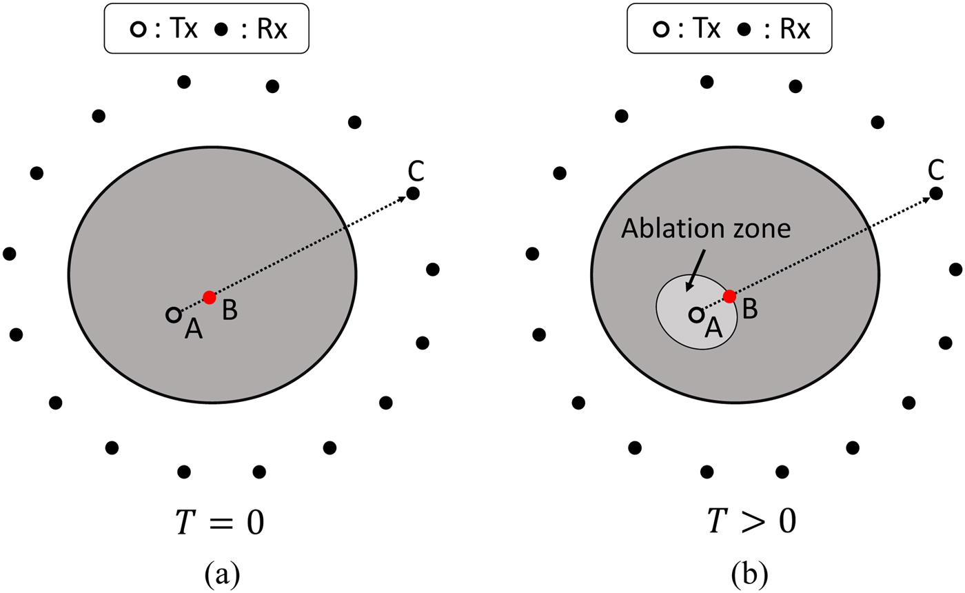
Investigations have shown that MWA leads to a decrease of the relative permittivity of tissues, mainly due to dehydration. The lower relative permittivity of the ablation zone leads to a smaller time delay from source to receiver, compared with the pre-ablation case. Our method exploits this principle through TDOA for extracting the ablation boundary.
Let τ 0 and τ n be the times of arrival of the pre- and during ablation signals, received at a location C, respectively. Each time of arrival can be decomposed as follows:
 $$\tau _0 = \tau _0^{AB} + \tau _0^{BC}, $$
 $$\tau _n = \tau _n^{AB} + \tau _n^{BC}, $$
where τ AB and τ BC denote the time of arrivals from r A (source location) to r B (ablation boundary point), and r B to r C (receiver location), respectively, as shown in Fig. 1. We define  $\epsilon _n^{AB} $ as the average dielectric constant of the tissue inside the ablation zone at the nth snapshot at the center frequency f 0 of the transmitted pulse, and $\epsilon _0^{AB} $ represents the average dielectric constant pre-ablation at frequency f 0, which corresponds to that of malignant tissue. In addition, $\tau _0^{BC} \simeq \tau _n^{BC} $, because the dielectric properties of the tissue between B and C are invariant. Then, the TDOA between pre- and during ablation cases can be expressed approximately as follows:
 $$\eqalign{{\rm \Delta} \tau & \equiv \tau _0 - \tau _n, \cr & \simeq \left( {1 - \sqrt \xi} \right)\tau _0^{AB},} $$
where 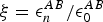 $\xi = \epsilon _n^{AB} /\epsilon _0^{AB} $. From equation (3), we can estimate the distance from source to boundary point as follows:
 $$\eqalign{R^{AB} \equiv \parallel \!{\bi r}_A - {\bi r}_B \!\parallel & = v_0\tau _0^{AB} \cr & = v_0\displaystyle{{\Delta \tau} \over {1 - \sqrt \xi}},} $$
where v 0 denotes the propagation velocity in the pre-ablation medium. Then, the ablation boundary point rB is given by:
 $${\bi r}_B = R^{AB}\; \hat {\bi u} + {\bi r}_A,$$
where  ${\bi \hat u}$ denotes a unit vector from rA to rC.
Note that, Δτ can be estimated from the following cross-correlation calculation:
 $${\rm \Delta} \tau = \mathop {{\rm arg\; max}}\limits_\tau [s_0\left( {{\bi r}_C,t} \right) \, \ast \, s_n\left( {{\bi r}_C,t} \right)]\left( \tau \right), $$
where  ${ \ast} $ denotes the operator of cross-correlation. If the number of receivers is M, then M different boundary points rB can be estimated.
The procedure for estimating the boundary of the ablation zone at the nth temporal snapshot in time is summarized as follows:
Step 1. Received signals are recorded at T = 0 (before the ablation begins) and at the nth temporal snapshot during the ablation.
Step 2. A noise reduction filter, such as matched filter, is applied to both observed signals.
Step 3. The TDOA value (Δτ) is determined from the peak shift of cross-correlation functions as in equation (6).
Step 4. The boundary point r B of the ablation zone is determined using Δτ, the relative permittivity around the transmitter for both pre- and during-ablation cases, as in equations (4) and (5), and the direction vector between source and receiver.
The most notable feature of this method is that it only requires the following as a priori knowledge: (1) an estimate of the average velocity in the medium surrounding the source before the ablation begins, and (2) an estimate of the ratio of the pre-ablation and ablated-tissue dielectric constant in the target region. The average velocity estimate may be obtained from an assumed spatially averaged dielectric constant of the target tissue pre-ablation. In most cases, the source will be located inside malignant tissue, whose dielectric properties are available in the literature [Reference Lazebnik17]. Furthermore, the properties of ablated tissue, and thus the ratio ξ, can be determined from the growing database of dielectric properties of ablated tissue [Reference Lopresto, Pinto, Lovisolo and Cavagnaro10, Reference Mays12].
III. THE 2D NUMERICAL SIMULATION EXAMPLES
A) Breast phantom and simulated array measurements
We tested our method using simulated measurements of two realistic breast phantoms derived from MRIs of healthy women [Reference Zastrow, Davis, Lazebnik, Kelcz, Van Veen and Hagness18]: a Class 3 “heterogeneously dense” phantom (ID number 062204), and a Class 4 “very dense” (ID number 012304) phantom. These phantoms are available online at the University of Wisconsin repository [19]. Here, we conducted 2D finite-difference time-domain (FDTD) simulations using in-house University of Wisconsin–Madison codes. The frequency-dependent complex permittivities for skin and breast tissues in the phantoms are modeled by using single-pole Debye models with parameters suitable for the frequency range of 0.5–3.5 GHz, as in [Reference Shea, Kosmas, Hagness and Van Veen20]. Figure 2 shows the map of the Debye parameter Δε of the Class 3 and 4 phantoms. The transmitting source, shown as a hollow black circle in Fig. 2, is located inside fibroglandular tissue. The average pre-ablation relative permittivity of the tissue surrounding the antenna was  $\epsilon _0^{AB} = 47$, which corresponds to the median value for healthy fibroglandular tissue at f 0 = 2.45 GHz. The 21 receiving antennas, shown as solid black circles in Fig. 2, are located on a ring outside breast (immersed in air) with equal spacing between them.
2D numerical breast phantom and configuration used to evaluate the performance of the TDOA-based MWA monitoring algorithm. The colorbar displays the Debye parameter, Δε. The hollow black circle denotes the location of the transmitting antenna, while the solid circles denote the locations of the receiving antennas. (a) Class 3 (heterogeneously dense) breast phantom. (b) Class 4 (extremely dense) breast phantom.

We modeled the impact of ablation as a 40% uniform decrease (ξ = 0.6) in all Debye parameters (e.g., ε inf, Δε, and σ) within the ablation zone; thus the dielectric properties in the ablation zone are also heterogeneous. This percentage drop has been observed in ablations of bovine liver tissue that has reached 99° [Reference Lopresto, Pinto, Lovisolo and Cavagnaro10] and human mastectomy specimens [Reference Mays12]. We modeled the ablation zone as an ellipse spanning 20 mm along the x-axis and 16 mm along the y-axis at the particular instance in time when the “measured” signals are recorded.
The transmitted signal is a Gaussian modulated pulse, with 2.45 GHz as the center frequency and a 1.9 GHz full 3 dB bandwidth. The received signals are computed using FDTD on a 0.5 mm grid. White Gaussian noise is added to each recorded electric field temporal waveform. The SNR is defined as the ratio of the average signal power to noise power in the time domain. We consider SNR levels of 30, 20, 10, 0, and −10 dB. A matched filter is applied to the received signals in the pre-processing step for noise reduction.
B) Boundary estimation results for different SNR cases
Figure 3(a) shows as an example the time-series signals recorded at r C = (133 and 66 mm) for the Class 3 phantom before and during ablation. The representative received signal recorded during the ablation is slightly shifted earlier in time compared with the signal pre-ablation, due to the decrease in relative permittivity of the ablation zone. Figure 3(b) demonstrates that, even in this dispersive and heterogeneous case, the ablation waveform is not significantly distorted relative to the pre-ablation signal. This empirically demonstrates the validity of the approximations made in the proposed algorithm.
(a) Electric field intensities observed at a representative receiver location (rC = (133 and 66 mm)) in the Class 3 phantom. The observations are made pre-ablation and when the ablation zone is an ellipse with the major axis (x-axis) of 10 mm and the minor axis (y-axis) of 8 mm. (b) Cross-correlation result for the signals observed in (a). Δτ marks the TDOA for the representative receiver location.

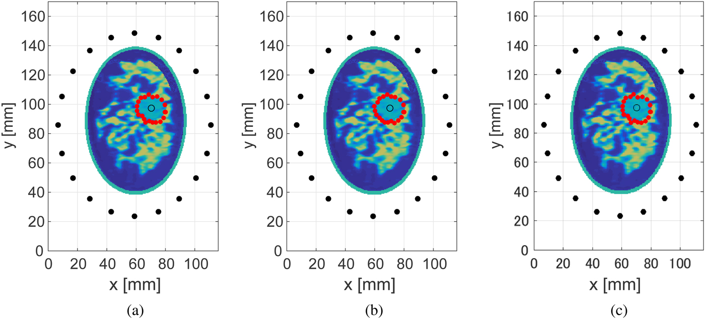
Figures 4 and 5 show the estimated ablation zone in the case of the Class 3 and 4 phantoms for three different SNR levels. The red solid circles denote the boundary points estimated by our proposed algorithm. These results demonstrate that the proposed method provides an accurate boundary reconstruction of the ablation zone, even for low levels of SNR. This robust performance in the presence of noise is mainly due to the application of the noise-reduction filter. The required computation time to construct the estimated boundary was <0.1 s using an Intel Core i5 CPU 3.3 GHz, with 8 GB RAM.
Estimated boundary, shown by the red circles, of the elliptical ablation zone in the Class 3 numerical breast phantom, for different levels of SNR. (a) 20 dB. (b) 10 dB. (c) 0 dB. The actual ablation zone is an ellipse with the major axis (x-axis) of 10 mm and the minor axis (y-axis) of 8 mm.

Estimated boundary, shown by the red circles, of the elliptical ablation zone in the Class 4 numerical breast phantom, for different levels of SNR. (a) 20 dB. (b) 10 dB. (c) 0 dB. The actual ablation zone is an ellipse with the major axis (x-axis) of 10 mm and the minor axis (y-axis) of 8 mm.
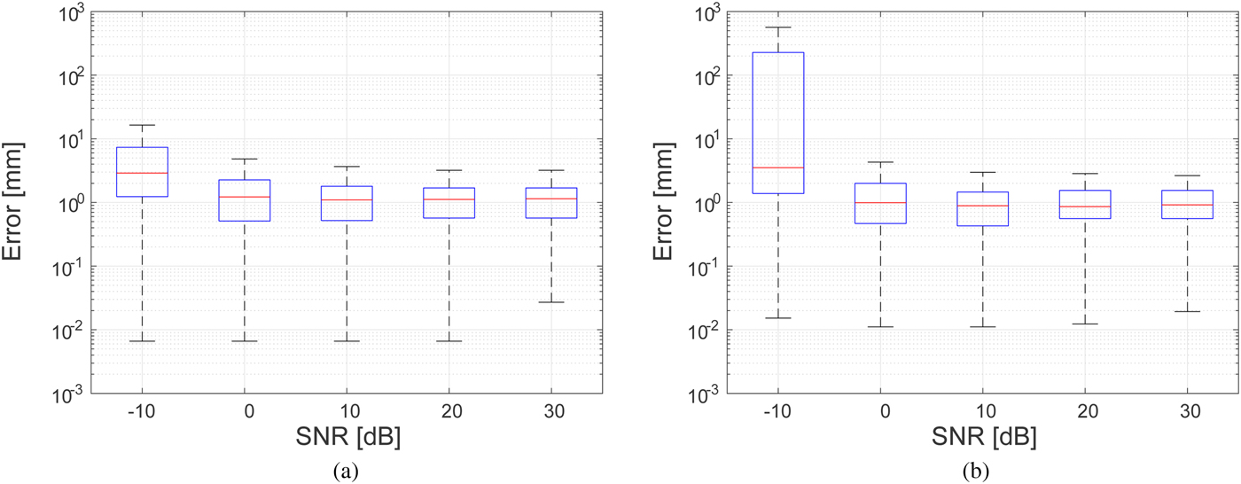
We define the reconstruction error for a specific estimated boundary point, rB, as the shortest distance from that estimated boundary point to the actual boundary. Figure 6 shows the box plots of the estimation errors for the Class 3 and 4 phantoms over M = 20 estimated boundary points for 100 different noise realizations at each value of SNR. The lower and upper bounds of the boxes span the interquartile range (IQR) and the lower and upper whisks denote the ± 2.7 standard deviation (S.D.) range. These results demonstrate that if the SNR is >−10 dB, the proposed method can maintain a median error within 4 mm in either phantom.
Errors in ablation zone boundary estimation as a function of SNR for 100 noise instances at each SNR level. (a) Class 3 numerical breast phantom. (b) Class 4 numerical breast phantom.
C) Impact of frequency bandwidth on performance
Next we present the results of an investigation of the impact of the bandwidth of the transmitted signal on the accuracy of the boundary estimation technique. Figure 7 shows the estimated boundary of the ablation zone for different effective bandwidths in a noiseless scenario for the Class 3 phantom. A zero-phase Gaussian bandpass filter (BPF) centered at 2.45 GHz is applied to each received signal recorded in the FDTD simulations to synthesize waveforms for six different full 3 dB bandwidths, ranging from 0.2 up to 1.8 GHz. The accuracy of the estimated boundary degrades as the bandwidth decreases.
Estimated ablation zone boundary in the Class 3 phantom for various bandwidths of transmitted signals. The black solid line shows the actual boundary.
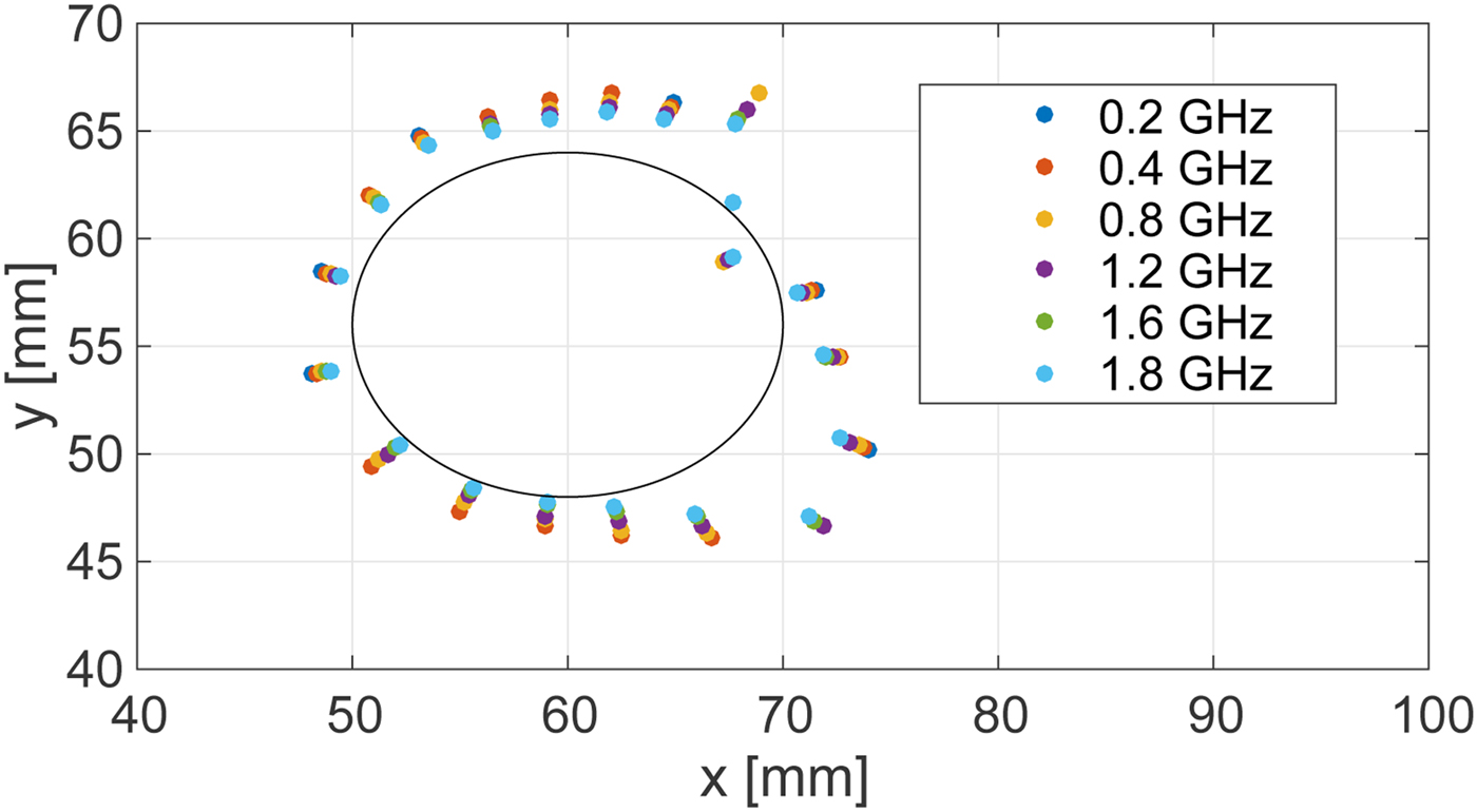
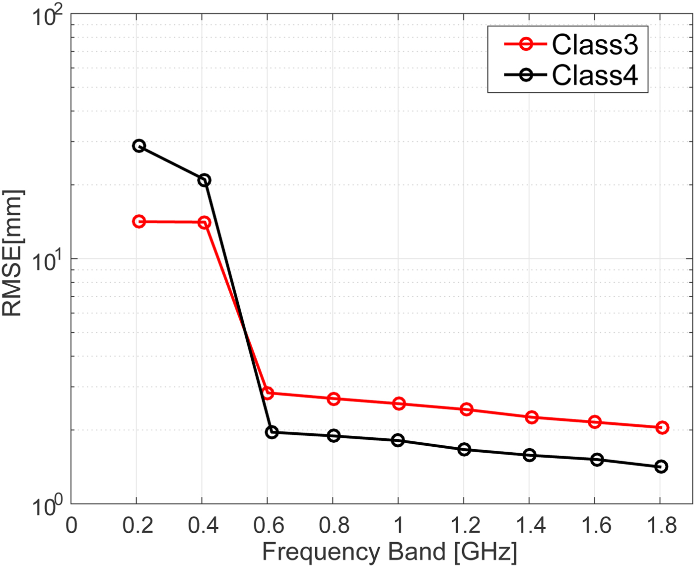
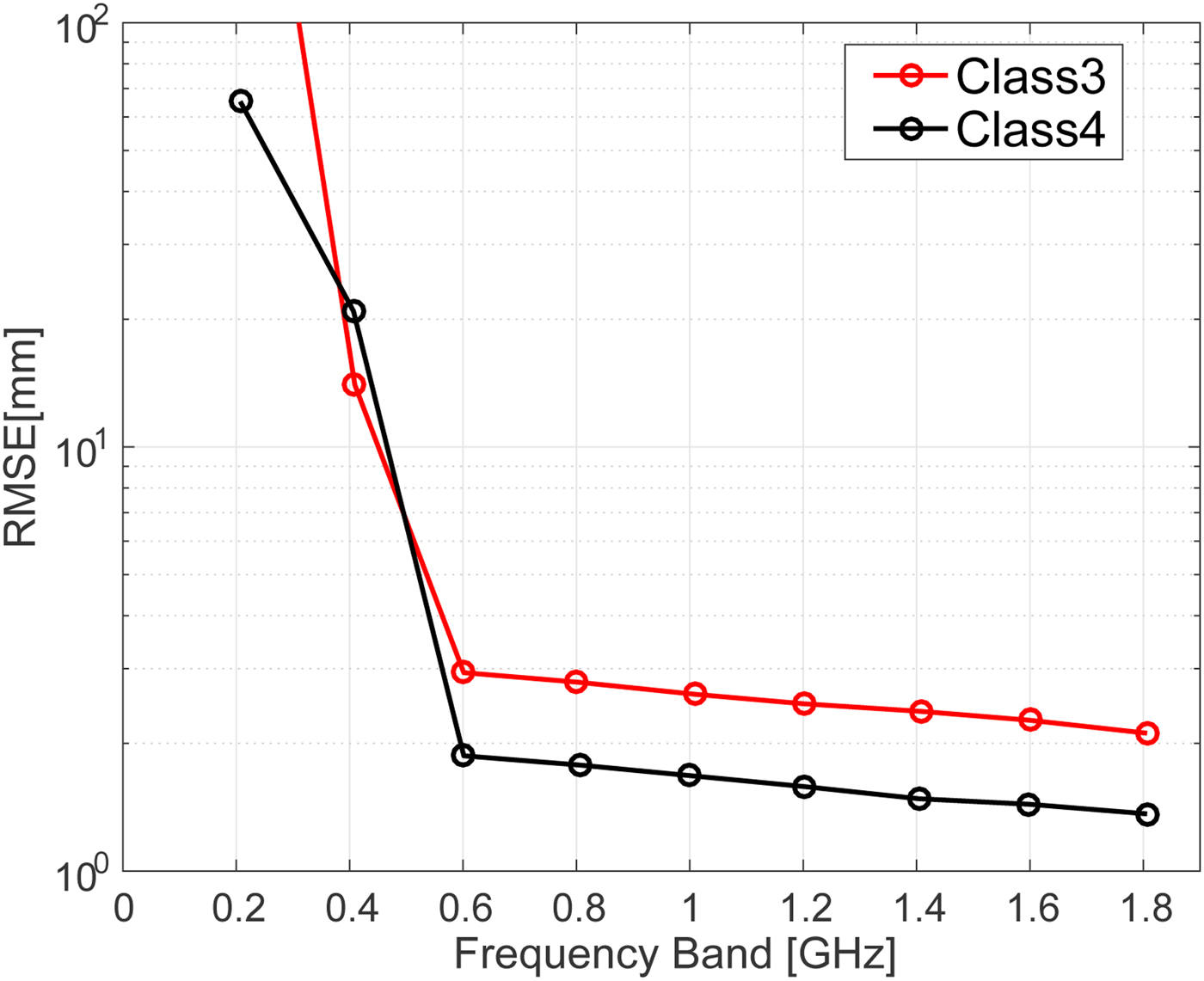
Figure 8 shows the root mean square error (RMSE) of the estimations for different bandwidths in the absence of noise. Very large errors are observed when the full 3 dB bandwidth is below 0.5 GHz. These large errors could be reduced by incorporating the knowledge of the actual breast size, as the ablation boundary should not be outside from the breast. Figure 9 shows the RMSE of the estimations for different bandwidths for an SNR of 20 dB. The results indicate that noisy signals with smaller bandwidths are more susceptible to errors in the difference of time of arrival calculation. Regardless of the noise level, however, our proposed method achieves an accurate estimate, with <3 mm RMSE, for bandwidths >0.7 GHz.
RMSE of ablation zone boundary estimations as a function of transmitted signal bandwidth for the Class 3 (black) and Class 4 (red) numerical breast phantoms in the absence of noise.
RMSE of ablation zone boundary estimations as a function of transmitted signal bandwidth for the Class 3 (black) and Class 4 (red) numerical breast phantoms with an SNR of 20 dB.
D) Sensitivity to receiver location errors
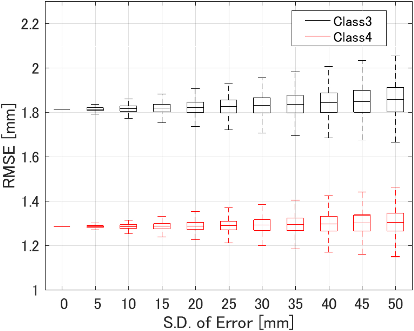
All of the results reported up to this point have been obtained for scenarios where we made use of the full knowledge of the receiver locations. Here we address the question of how well the algorithm performs when there are errors in the assumed locations of the receivers. We added Gaussian random fluctuations to each assumed receiver location. Figure 10 shows the results for the Class 3 and 4 numerical breast phantoms, when the S.D. of the Gaussian distribution is assumed to be 10 mm for the both x- and y-axes. The results indicate that such errors do not severely affect the accuracy of the reconstruction. This finding is not surprising because our method only uses the receiver locations to determine a direction from the transmitter along which to place the estimated ablation boundary point. This insensitivity to assumed receiver location error is in fact a significant advantage of this method. Finally, Fig. 11 shows the statistical analysis for varying location mismatch levels, for the Class 3 and 4 phantoms. Here, the lower and upper bounds of the box span the IQR for 1000 different realizations of Gaussian errors that were tested for each S.D. value. The RMSE is <2.0 mm for both phantoms, even when the location mismatch is of the order of 50 mm. This evaluation confirms that our method is robust to misalignments of sensors or imprecise knowledge of sensor locations.
Estimation results when there are errors in the assumed receiver locations. Black and magenta solid circles denote the actual and assumed receiver locations, respectively. The S.D. of the errors in the assumed receiver locations is 10 mm. (a) Class 3. (b) Class 4.

RMSE of ablation zone boundary estimations as a function of the S.D. of errors in the assumed receiver locations for 1000 different instances in each phantom.
E) Sensitivity to the assumed dielectric constant of tissue pre-ablation
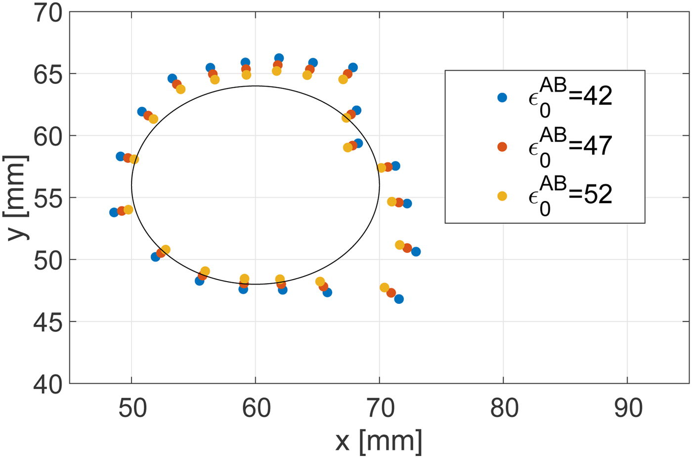
Here we consider the impact of a mismatch between the actual dielectric constant of the target tissue pre-ablation and that which is assumed and incorporated into the algorithm's value for v 0. Such a mismatch would arise due to any patient-to-patient variability in the dielectric properties of the target tissue, i.e. malignant tumor. Lazebnik et al. [Reference Lazebnik17] reported that there is relatively small variability in malignant breast tissue properties; namely, the difference in the dielectric constant between the 25th or 75th percentile value and the median value is less than 10%. Figure 12 shows the ablation boundary estimated by the proposed method in a Class 3 breast phantom, when there is a  $ \pm 10\% $ mismatch between the actual and assumed baseline (pre-ablation) dielectric constant in the target region. The RMSE is 2.31 mm for $\epsilon _0^{AB} = 42$ and 1.45 mm for $\epsilon _0^{AB} = 52$. For reference, the case without mismatch (ε 0 = 47) yielded an RMSE of 1.81 mm. These results indicate that the algorithm is not sensitive to errors in the assumed dielectric constant on the order of ±10% that would arise due to variability in the actual properties from one patient to the next. The impact of such mismatch on the estimated location of the boundary is less than 1 mm.
Estimated ablation zone boundary in the Class 3 phantom for various assumed dielectric constants of the pre-ablation tissue that are incorporated into the TDOA algorithm. The black solid line shows the actual boundary. The actual dielectric constant of the target tissue, pre-ablation, in the breast phantom is 47.
IV. THE 3D NUMERICAL SIMULATION EXAMPLES
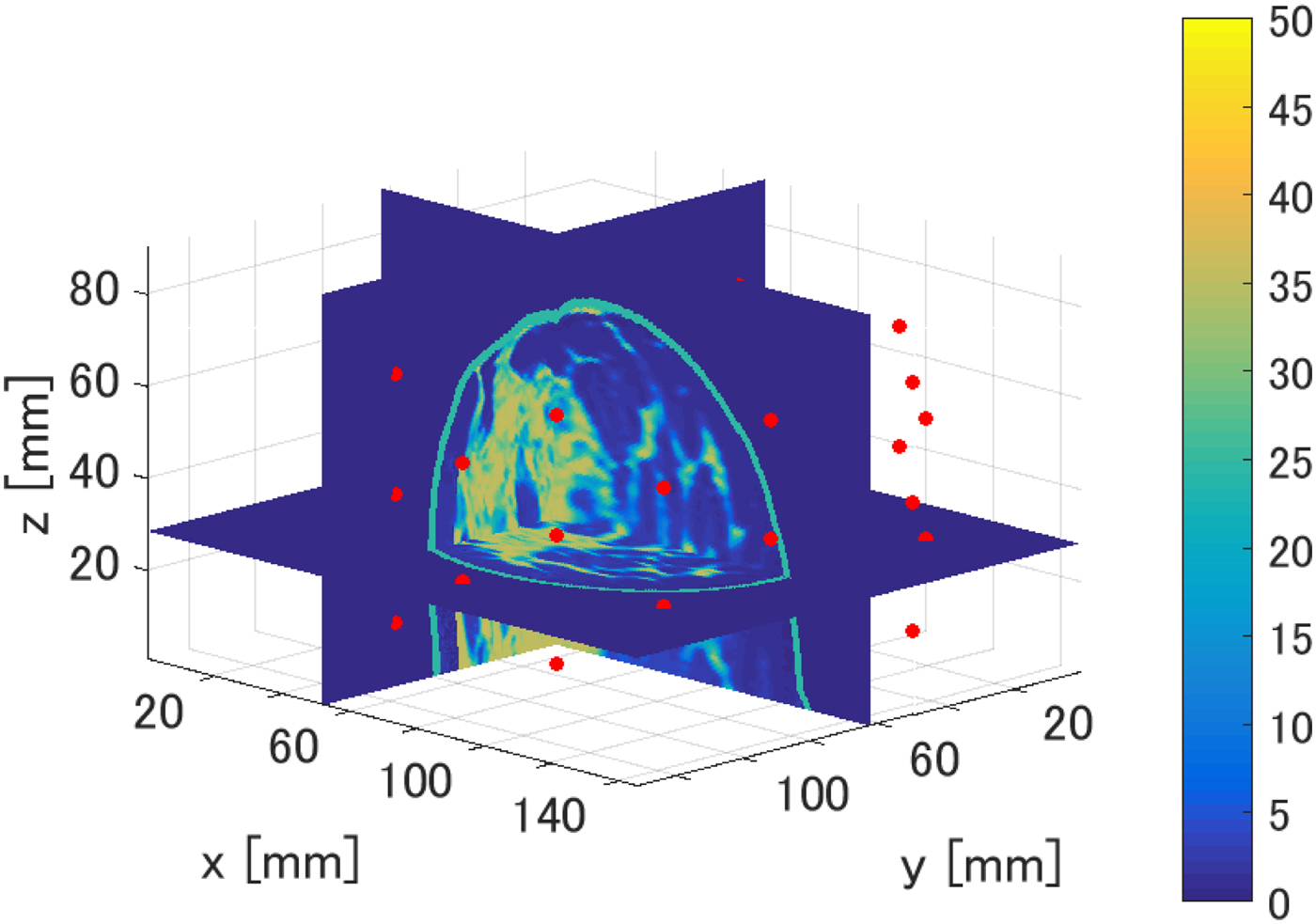
In this section, we present the results of our investigation of the TDOA-based MWA monitoring algorithm in 3D. Figure 13 shows cross sections of the 3D map of the Debye parameter, Δε, for the same Class 3 phantom considered in the 2D investigations. 3D FDTD simulations were conducted using in-house University of Wisconsin–Madison codes. The transmitting source is an electrically short dipole located within a region of fibroglandular tissue at (x, y, z) = (62.5, 52.5, 28.5 mm). The ablation zone (not shown in Fig. 13) is modeled as an ellipsoid with axial radii of 10 mm (x-axis), 7.5 mm (y-axis), and 10 mm (z-axis). The dielectric properties are reduced by 40% as in the case of the 2D phantoms. The receiving antenna array surrounding the breast phantom consists of 40 electrically short dipoles, where each dipole arm is 2 mm long and the feed gap is 0.5 mm. These receiving antennas are evenly distributed on five elliptical rings of eight antennas each, with adjacent rings rotated by 22.5° to create a staggered array of antennas in the vertical direction. The five rings are located on xy planes located at z = 14.5 mm, z = 28.5 mm, z = 42.5 mm, z = 54.5 mm, and z = 68.5 mm. The dimensions of the major and minor axes of the array's elliptical cross-section are chosen such that the array conforms to the phantom with a minimum spacing of 1 cm between each antenna element and the skin surface. The transmitted signal is a Gaussian-modulated pulse, with 2.45 GHz as the center frequency and a 1.9 GHz full 3 dB bandwidth. The 3D computational domain is composed of 0.5 mm cubic grid cells. The antenna measurements are observations of the copolarized electric field component in the feed gap. The time-domain fields are recorded at every antenna in the external array.
3D numerical breast phantom and configuration used to evaluate the performance of the TDOA-based MWA monitoring algorithm. The colorbar displays the Debye parameter, Δε. The red circles denote the locations of the 40 electrically short receiving dipole antennas located on elliptical rings surrounding the breast phantom.
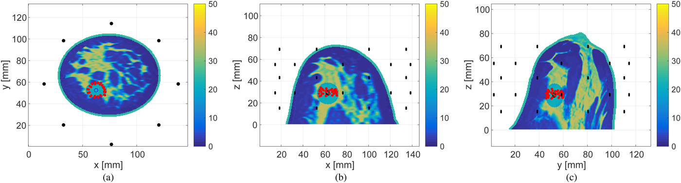
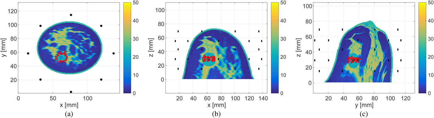
Figures 14 and 15 show the estimated boundary points on each of three orthogonal projection plane for 30 and 0 dB SNR scenarios, respectively. The required processing time to reconstruct the boundary of the ablation zone is 0.1 s, using an Intel Core i5 CPU 3.3 GHz, with 8 GB RAM. The limited extent of the reconstruction in the z-direction is due to the limited-height cylindrical array configuration with no anterior coverage of the breast.
Estimated boundary, shown by the red circles, of the ellipsoidal ablation zone in the 3D Class 3 numerical breast phantom for SNR = 30 dB. The actual ablation zone is an ellipsoid with axial radii of 10 mm (x-axis), 7.5 mm (y-axis), and 10 mm (z-axis). (a) z-plane projection. (b) The y-plane projection. (c) The x-plane projection.
Estimated boundary, shown by the red circles, of the ellipsoidal ablation zone in the 3D Class 3 numerical breast phantom for SNR = 0 dB. The actual ablation zone is an ellipsoid with axial radii of 10 mm (x-axis), 7.5 mm (y-axis), and 10 mm (z-axis). (a) z-plane projection. (b) The y-plane projection. (c) The x-plane projection.
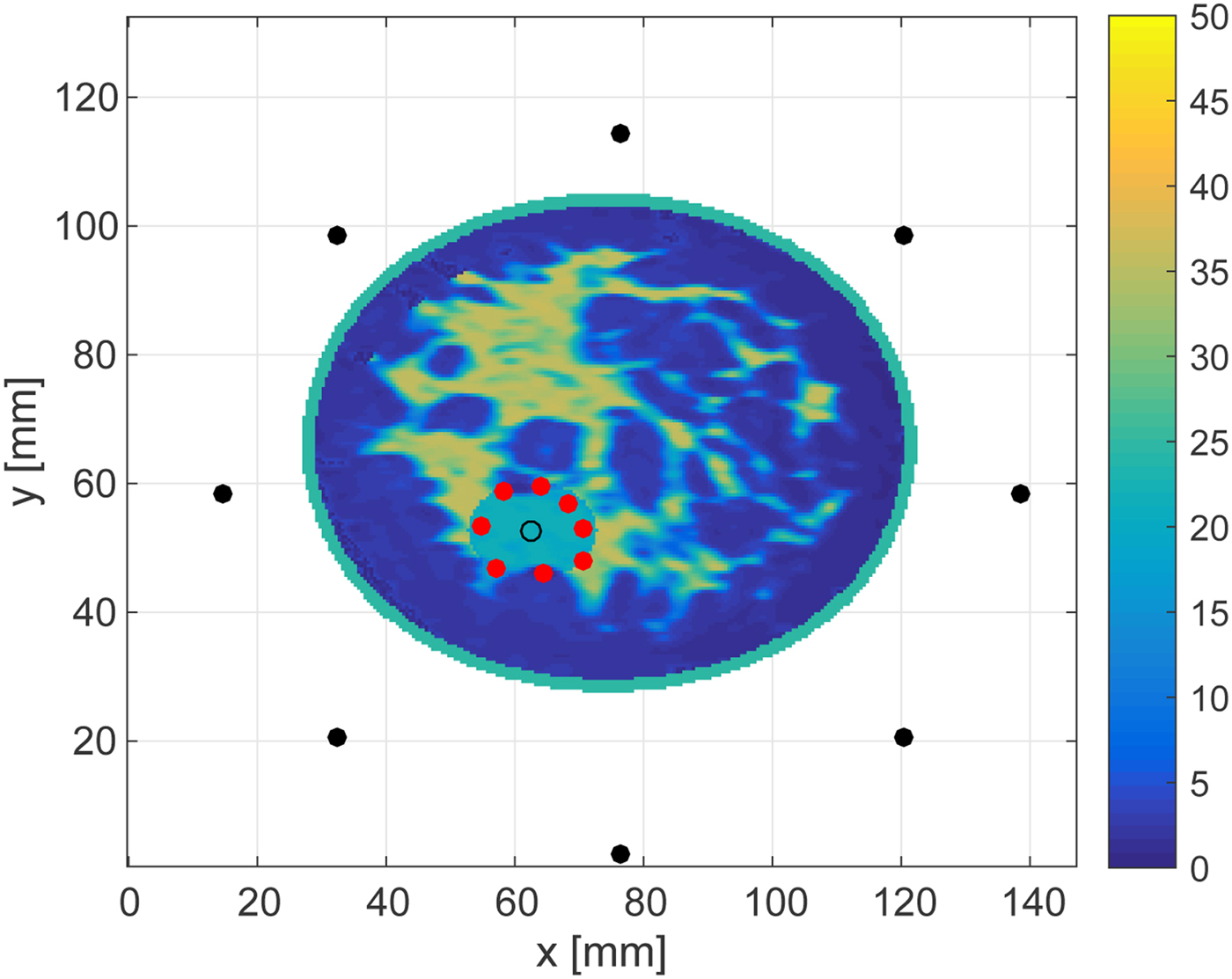
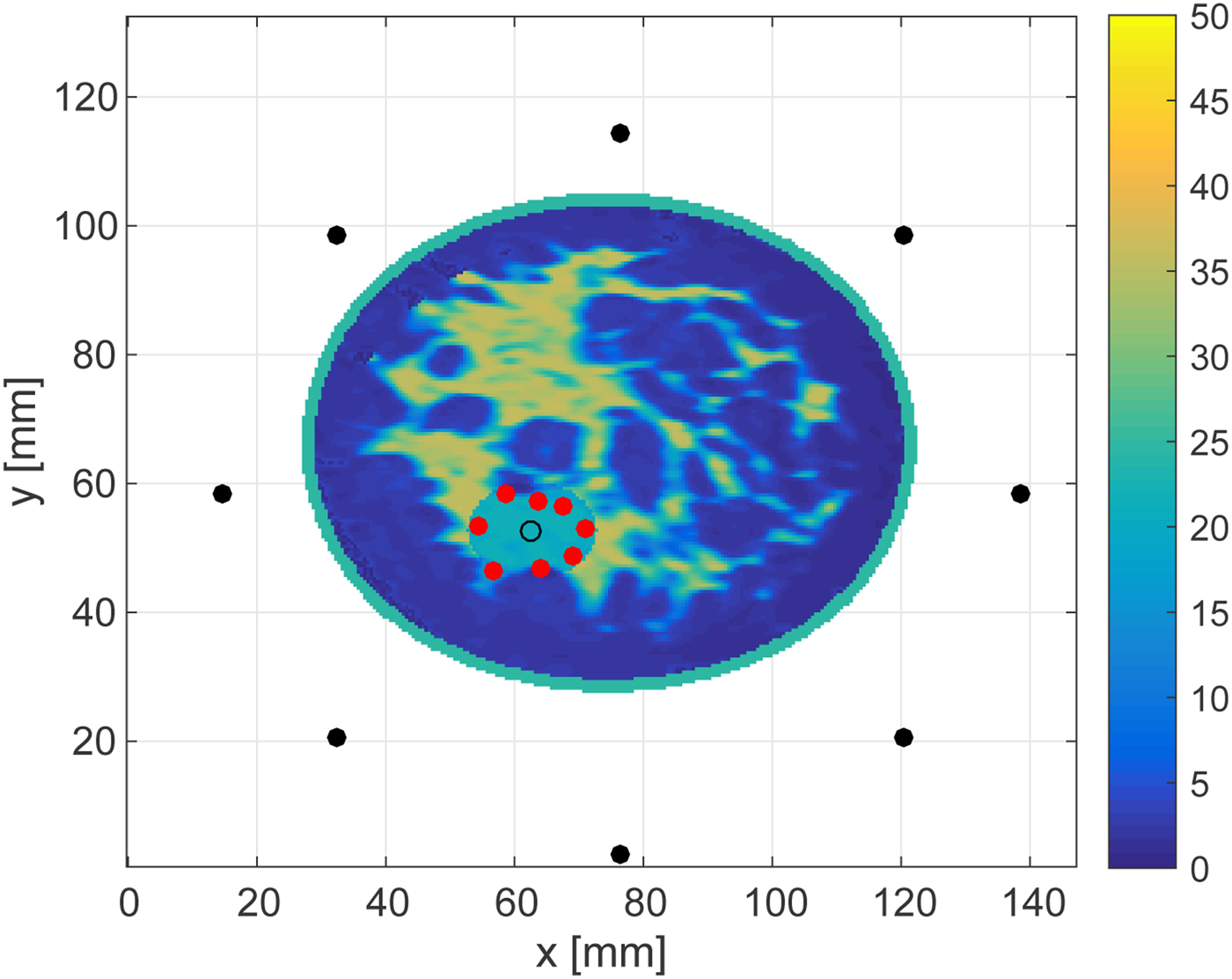
Figures 16 and 17 show the cross-sectional views in an x − y plane at z = 28.5 mm. These views enable us to quantitatively assess the accuracy as the source, receivers and each estimated point are in the same plane. The RMSEs of the boundary estimations for the 30 and 0 dB SNR cases are 1.25 and 1.54 mm, respectively. These results demonstrate that the proposed algorithm achieves highly accurate boundary estimation in 3D MWA monitoring, even for rather low levels of SNR.
Cross-sectional plane at z = 28.5 mm showing the in-plane results reported in Fig. 14.
Cross-sectional plane at z = 28.5 mm showing the in-plane results reported in Fig. 15.
V. CONCLUSION
This paper proposes a real-time ablation zone monitoring algorithm that exploits TDOA between signals transmitted by the interstitial MWA antenna to external array elements before the ablation begins and during the ablation. Our proposed algorithm requires minimal a priori knowledge: only an estimate of the relative permittivity of the tissue in the local treatment zone before the ablation begins, and an estimate of the change in relative permittivity of that tissue due to ablation. This is a definitive advantage of our method. The 2D and 3D numerical examples presented demonstrate that the proposed algorithm achieves accurate estimates of the ablation zone boundary, even in situations involving low SNR. Although our algorithm makes several simplifying wave propagation approximations, the investigations reported here involving highly realistic FDTD models of the breast demonstrate that the approximations inherent in the algorithm are acceptable. However, it should be noted that there are some errors in the boundary estimation, even for higher SNR levels, especially for the Class 3 phantom. Such errors most likely arise due to the assumption of line-of-sight propagation. In reality, the signals propagating from the internal transmitter to each external receiver undergo varying degrees of scattering in the highly heterogeneous environment of the breast. The degree of errors introduced by the line-of-sight assumption depends on the transmitter and receiver locations and the specific tissue heterogeneity, as illustrated by the difference in performance in the specific Class 3 and 4 scenarios considered here. Nevertheless, a real-time MWA monitoring algorithm capable of estimating the ablation zone boundary with errors of the order of only a few millimeters, as demonstrated here, would be highly useful in clinical applications, suggesting that this promising technique warrants further development.
ACKNOWLEDGEMENTS
This work was supported by Strategic Information and Communications R & D Promotion Programme (SCOPE), Grant Number 162103102 promoted by Japanese Ministry of Internal Affairs and Communications, and the Lynn H. Matthias and Philip D. Reed professorships at the University of Wisconsin-Madison.
 Shouhei Kidera received his B.E. degree in Electrical and Electronic Engineering from Kyoto University in 2003 and M.I. and Ph.D. degrees in Informatics from Kyoto University, Kyoto, Japan, in 2005 and 2007, respectively. He has been with Graduate School of Informatics and Engineering, the University of Electro-Communications, Tokyo, Japan, since 2009, and is currently an Associate Professor. He worked in the Cross-Disciplinary Electromagnetics Laboratory in the University of Wisconsin Madison as the visiting researcher in 2016. His current research interest is in advanced radar signal processing for ultra wideband (UWB) three-dimensional sensor or bio-medical applications. He was recipient of the 2013 Young Scientist's Prize by the Japanese Minister of Education, Culture, Sports, Science and Technology (MEXT), and 2014 Funai Achievement Award. He is a member of the Institute of Electrical and Electronics Engineers (IEEE) and of the Institute of Electronics, Information, and Communication Engineers of Japan (IEICE), Japan.
 Luz Maria Neira received the B.S. degree with highest honors in industrial engineering with Diploma in electrical engineering from Pontificia Universidad Catolica de Chile (Santiago, Chile) in 2009, and the M.S. degree in Electrical Engineering from the University of Wisconsin-Madison (Madison, WI, USA) in 2016. Since September 2013, she has been working toward the Ph.D. degree in Electrical Engineering at the University of Wisconsin-Madison. Her research interests include microwave imaging for diagnostic and therapeuticbiomedical applications. Ms. Neira received the University of Wisconsin-Madison Chancellor's Opportunity Fellowship in 2013 and a first prize award in the USNC-URSI Student Paper Competition at the 2015 IEEE International Symposium on Antennas and Propagation and North American Radio Science Meeting in Vancouver, BC, Canada.
 Barry D. Van Veen received the B.S. degree from Michigan Technological University in 1983 and the Ph.D. degree from the University of Colorado in 1986, both in Electrical Engineering. He is currently Lynn H. Matthias Professor of Electrical and Computer Engineering at the University of Wisconsin-Madison. His research interests include signal processing for sensor arrays and biomedical applications of signal processing. Dr. Van Veen was a recipient of a 1989 Presidential Young Investigator Award from the National Science Foundation and a 1990 IEEE Signal Processing Society Paper Award. He received multiple teaching awards at the University of Wisconsin, including the 2014 Spangler Award for Technology Enhanced Instruction, the 2015 Chancellor's Distinguished Teaching Award, and the 2017 Benjamin Smith Reynolds Award for Teaching Engineers. He coauthored “Signals and Systems,” (1st Ed. 1999, 2nd Ed., 2003 Wiley) with Simon Haykin and is the publisher of allsignalprocessing.com.
 Susan C. Hagness received the Ph.D. degree in Electrical Engineering from Northwestern University in 1998. She is currently the Philip D. Reed Professor of Electrical and Computer Engineering at the University of Wisconsin-Madison, where she served as the 2014–2017 Associate Dean for Research and Graduate Affairs in the College of Engineering. She has received a number of international research and teaching awards, including the IEEE Engineering in Medicine and Biology Society Early Career Achievement Award (2004), URSI Issac Koga Gold Medal (2005), IEEE Transactions on Biomedical Engineering Outstanding Paper Award (2007), IEEE Education Society Mac E. Van Valkenburg Early Career Teaching Award (2007), and Physics in Medicine and Biology Citations Prize (2011). Dr. Hagness has chaired the Fellows Committee and Technical Program Committee for the IEEE Antennas and Propagation Society and served on the Fellows Committee for the IEEE Engineering in Medicine and Biology Society, among other society leadership roles.


 Open access

