

1. Introduction
Powder-snow avalanches are destructive and notoriously unpredictable geophysical phenomena. They are gravitational flows of dry, fine snow suspended in air that usually start on steep slopes (Reference SimpsonSimpson, 1997). A defining feature of the flow is the very high driving density differences between the snow suspension and the surrounding ambient air: the density ratio can exceed 20. To maintain these density differences, the avalanche must entrain large volumes of snow from its path to counteract dilution by the entrainment of ambient air. The airflow inside the suspension must also be sufficiently turbulent to support the snow particles in suspension, counteracting particle sedimentation. This particle suspension, or powder cloud, is usually accompanied by a dense granular flow of snow beneath. The two avalanche components have distinct dynamics linked only by a mass exchange between them. In this paper, we use the term ‘powder-snow avalanche’ to mean any snow avalanche where a powder cloud forms. It is the dynamics of this powder cloud that we are primarily interested in.
Laboratory experiments on powder-snow avalanches are important for validating and developing theory (Reference Beghin, Hopfinger and BritterBeghin and others, 1981; Reference AnceyAncey, 2004). Compared to field experiments, they have the advantages of better-defined boundary conditions and being relatively inexpensive to run. We have recently developed an experiment with the correct similarity criteria to physically model powder-snow avalanches which replicates initiation from a dense flow of snow (Reference Turnbull and McElwaineTurnbull and McElwaine, 2008). The experiment generates finite-volume flows of dry fine snow in air on a steep open slope. These flows are fully three-dimensional (3-D); the complications of the lateral spreading increased the complexity of the analysis. In the present work, we performed similar experiments but in a narrow chute so that the system was pseudo two-dimensional (2-D). Other modifications were made to the experimental procedure to improve its reproducibility, facilitating comparison with theory.
In both the original and the present experiments we recorded images with two video cameras and mounted an air-pressure sensor flush with the chute surface, measuring the air-pressure history at the base of each flow. Flow-height and front-velocity data, generated from analysis of the video sequences, supported intuitive or well-known results. The flow height increased with slope angle and the front reached a steady velocity, the magnitude of which was approximately independent of slope angle (Reference Britter and LindenBritter and Linden, 1980; Reference Turnbull and McElwaineTurnbull and McElwaine, 2008). However, the air-pressure histories of the flows were not intuitive and merit elucidation. The objective of this work is to clarify our understanding of these air-pressure histories.
Typical Stokes numbers for both a powder-snow avalanche and our chute flows are ≪C1, and the motion of the particles in suspension is strongly dependent on the motion of the interstitial air and vice versa (Reference Batchelor, Germain, Piau and CaillerieBatchelor, 1989; Reference AnceyAncey, 2007). The motion of the suspension is therefore representative of the airflow inside a powder-snow avalanche, and the airflow is representative of the suspension motion.
Measurements of the dynamic air pressure from our snow chute (Reference Turnbull and McElwaineTurnbull and McElwaine, 2008), ping-pong ball avalanches on a ski jump (Reference McElwaine, Nishimura, McCaffrey, Kneller and PeakallMcElwaine and Nishimura, 2001), direct numerical simulations of non-Boussinesq clouds on an incline (Reference Étienne, Saramito and HopfingerEtienne and others, 2004) and avalanche air-pressure measurements from the field (Reference Grigoryan, Urumbayev and NekrasovGrigoryan and others, 1982; Reference Nishimura, Narita, Maeno and KawadaNishimura and others, 1989; Reference McElwaine and TurnbullMcElwaine and Turnbull, 2005) all have an important feature in common. A large negative pressure inside the head contrasts starkly with the traditional pressure assumption, which would predict a positive, hydrostatic pressure due to the weight of suspended particles. This incorrect assumption is used in shallow-water models of powder-snow avalanches or other suspension flows. In this work, we discuss the origin of the internal motion implied by this negative pressure peak.
The bulk of this work is concerned with modelling the airflow around the powder-snow chute flows. To do this, we consider the potential flow fields (i.e. inviscid and irrotational) around three contrasting but associated geometries. We first derive the flow field around a 2-D ellipse, accounting for the aspect ratio of the flow. This is linked to the flow around a disc, an ellipse of fixed aspect ratio 1 which is the dipole solution discussed in Reference McElwaine, Nishimura, McCaffrey, Kneller and PeakallMcElwaine and Nishimura (2001) and Reference McElwaine and TurnbullMcElwaine and Turnbull (2005). In the third model we use the result of Reference McElwaineMcElwaine (2005) which states that the front angle of a wedge flow must always be 60°. Given this angle of 60° at both the front and rear stagnation points, which forms a partial dome shape (referred to as 60° dome), the flow field in the surrounding ambient can also be solved, hence providing the external flow fields. This body has a fixed aspect ratio of ![]() and should more accurately reflect the flow geometry close to the front stagnation point than the ellipse or disc.
and should more accurately reflect the flow geometry close to the front stagnation point than the ellipse or disc.
Measured chute pressure signals up to the nose of the flows are fitted with each of these models to give the geometry and speed of the flow. The key advantage in using these types of model with a fitting process is that, from a single measurement, we can predict the external flow velocities and also the flow geometry. In addition, they can be combined with the internal flow model of Reference McElwaineMcElwaine (2005) to find the complete flow field, or coupled with integral models for the avalanche flow such as the Kulikovskiy-Sveshnikova-Beghin (KSB) model (Reference Fukushima and ParkerFukushima and Parker, 1990; Reference AnceyAncey, 2004; Reference Turnbull, McElwaine and AnceyTurnbull and others, 2007).
2. Experimental Method
The development of an experiment creating non-Boussinesq, self-igniting flows of dry snow in air on an open slope is fully discussed in Reference Turnbull and McElwaineTurnbull and McElwaine (2008). Solutions to practical problems in running the experiments, such as snow cohesion and instrumentation, are also provided. However, control of the initial conditions could be significantly improved and vibrations on the chute distorted the data. We released finite volumes of snow through a drop tube onto a sieve in the Reference Turnbull and McElwaineTurnbull and McElwaine (2008) experiments, breaking any sintered bonds between the snow grains. The sieved, powder snow dropped onto a steep chute down which it flowed, entraining ambient air, to form a suspension flow. The flows therefore replicated the transition from a dense to a suspension flow found in natural powder-snow avalanches. By using a steep slope, Richardson number similarity was preserved while non-Boussinesq density differences were maintained, correctly modelling the mixing between the snow suspension and the ambient air.
The original experiments were performed on an open slope and spread out laterally (fully 3-D), complicating the analysis and making steady flow states impossible. The aim of the present experiment was to remove this complication by creating flows in a narrow 0.2 m channel so that the flows are pseudo 2-D, i.e. with no lateral variations. There is then the possibility that a steady flow state develops, where entrainment of air on the upper surface exactly matches the sedimentation of the snow particles.
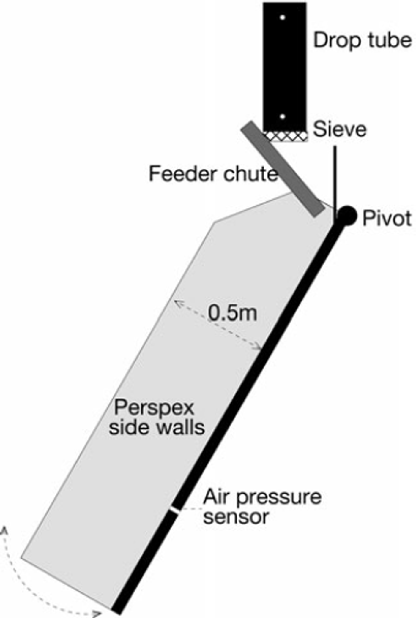
To improve the quality of data, we have designed a more sophisticated release system, allowing better-controlled release conditions while minimizing chute vibrations. In this new system the snow break-up mechanism, which counteracts sintering, is mechanically separate from the main chute (Fig. 1).
Side-view schematic of the experiment. The chute is 2 m long and 0.2 m wide. The angle can be varied between 40° and 90°. The feeder chute is fixed and delivers a dense flow onto the same part of the main chute regardless of the angle.
Crucially, we conducted the new experiment in a cold room at the Weissflühjoch (above Davos, Switzerland), allowing control of the ambient conditions. This significantly improved the reproducibility of the experiments and made their systematic execution more straightforward. In turn, this enabled us to capture the snow in each flow at the bottom of the chute and measure its mass. This is a more reliable measure than the release volume because not all the snow passes through the sieve; the same release volume can result in very differently sized avalanches. Three experiments were performed at each release volume (100, 200, 400, 800, 1000, 2000, 4000 and 8000 mL) and at each angle (44–90°). The flows remained dense on the shallow angles and gradually became more suspended as the slope angle became steeper.
As in our previous experiments, we tracked the flows using front-view and side-view video cameras. Video data recorded from the synchronized side- and front-view cameras were processed using a change point detection technique (Reference McElwaine, Naaim and Naaim-BouvetMcElwaine, 2002) that derived the front position and flow height at each time frame. We measured the airflow inside and around the flows with a pressure transducer mounted in the surface of the chute. A Validyne DP 103 sensor sampled data at a rate of 8 kHz. Although no frequency calibration curve is available for this sensor, the resonant frequency for the tubing (20 mm length) is 4 kHz and the electronic frequency response is 2.5 kHz. The actual sensor response will be less than this, but can provide good resolution at the scale of our experiments. Synchronization was achieved by optoelectronic sensors in the drop tube that send a pulse recorded by the data acquisition system when the snow is dropped. This system also illuminated two light-emitting diodes (LEDs) that were filmed by the cameras.
3. Measurements
Figure 2 shows side-view images from a dense flow on a shallow slope angle and from a fully suspended flow on a vertical slope. These show the structure of the snow–air flows, with darker regions of the photos being more dense than lighter regions. The de-interlaced images are shown with the chute surface horizontal and with an inverted colour scheme for clarity. The ‘nose’ corresponds to the front of the flow; the term ‘front velocity’ therefore refers to the time derivative of the nose position along the chute. The head structure of the f low is clear particularly at the steeper slope angle, with the nose raised above the chute surface. Time t = 0 represents the time at which the nose crosses the air-pressure sensor position.
Snapshots from the side-view video recordings of two 100 mL snow–air flows at the same scale: (a) dense flow on a 44° slope and (b) fully suspended flow on a 90° slope.
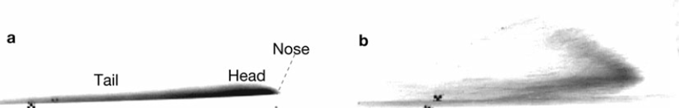
Figure 3 shows the air-pressure data from a 100mL flow on a 71° slope, which shows the typical features observed in signals from all of our flows. The pressure reaches a maximum positive peak at the nose corresponding to the compression arising from the mean flow velocity. Immediately after the nose inside the head, the pressure drops rapidly to a negative peak of similar magnitude to the positive peak. After reaching the negative peak inside the head, the air becomes turbulent in the tail and the pressure relaxes back to zero as the flow passes. This signal contrasts starkly with the hydrostatic pressure distribution depicted by the dotted line in Figure 3 that is often assumed when modelling suspension flows (Reference Von Kármánvon Karman, 1940).
Air-pressure history (relative to atmospheric pressure) of a 100 mL snow–air flow on a 71° slope (solid curve). This distribution contrasts with a hydrostatic pressure distribution (dotted curve) often assumed in modelling gravity flows.
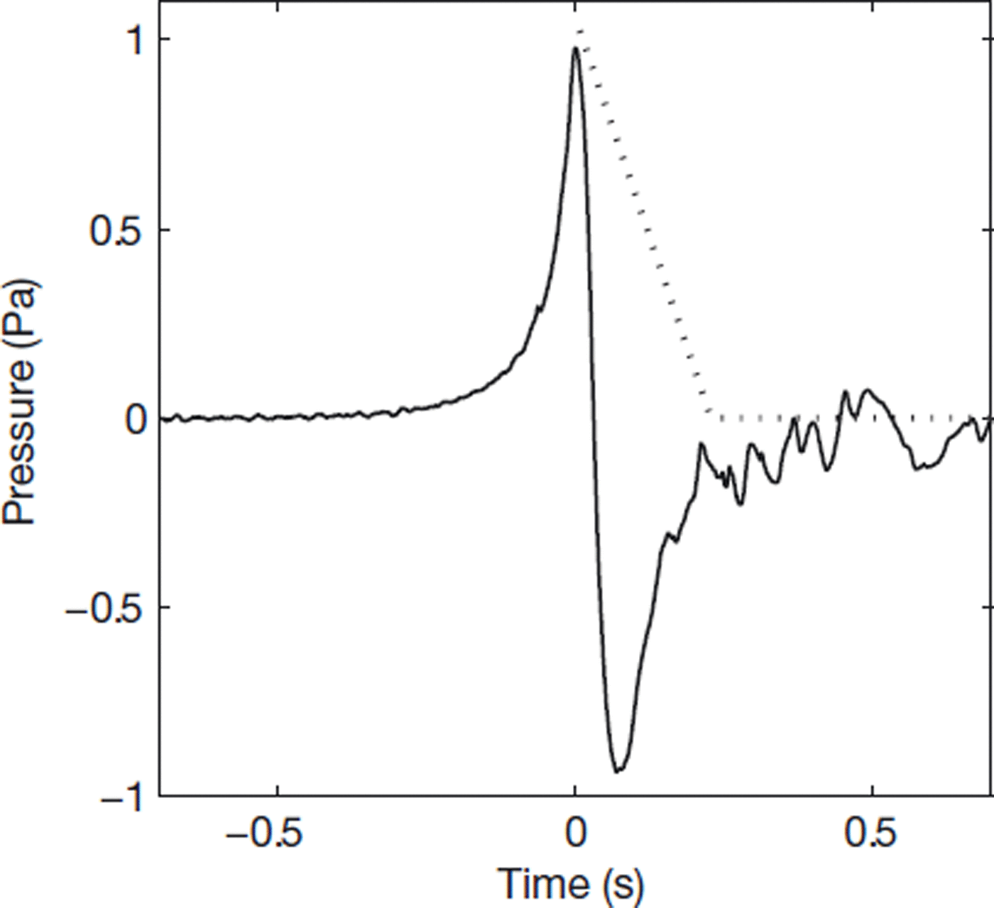
Such a large negative pressure inside the head of the flows indicates a high degree of internal motion in this region. A negative peak of the same magnitude as the positive peak, which scales with the square of the front velocity of the flow, implies that the internal flow velocities are of the same magnitude as the front speed of the flow.
3.1. Qualitative interpretation of the air-pressure signatures
Large internal motion means that careful consideration should be given to using the shallow-water equations, commonly applied in avalanche dynamics computations, for modelling these flows (Reference Harris, Hogg and HuppertHarris and others, 2002). The hydraulic approximation is invoked in deriving the shallow-water equations, assuming fluid velocity perpendicular to the base surface is negligible compared to fluid velocity parallel to the surface. The fluid velocity vector in shallow-water models is therefore parallel to the slope and constant throughout the depth of the fluid (Reference Landau and LifshitzLandau and Lifshitz, 1987).
A negative pressure of the scale observed on the chute has implications for the amount of damage a powder-snow avalanche could do to, for example, a forest or building. Flow guidelines assume that the pressure a powder-snow avalanche can exert on a body in the avalanche path is the stagnation pressure. For an avalanche of mean density pp and front velocity u, the stagnation pressure is
In relation to the chute air-pressure measurements, this stagnation pressure corresponds to the pressure of the positive peak at the nose of the flow. However, since the negative pressure peak is similar to the positive pressure peak, this suggests that there are coherent internal velocities of the same magnitude as the front velocity. The largest velocities may be as great as 2u or more; the peak pressures on an object could therefore be 4P 0 or more. The forces exerted on a body in an avalanche path will therefore be significantly greater than the impact pressures estimated by the Swiss guidelines.
This negative pressure also provides a strong and non-directional influence for the entrainment of loose snow particles from the snow cover or a dense granular flow beneath the powder-snow avalanche. Without entraining particles to maintain a high density compared to the surrounding ambient air, a powder-snow avalanche will run out over a short distance. With a large supply of particles and enough turbulence to support the particles in suspension, the powder-snow avalanche will grow and accelerate.
The pressure at the floor of a turbidity flow of sediment-laden water on a horizontal plane has been measured using a specially adapted differential transducer and compared to the vertical velocity fluctuations (measured with an ultrasonic anemometer) inside the flow. In this case, the fluid pressure inside the flow appears approximately hydrostatic. However, the vertical velocity fluctuations are positively correlated to the second-order variations in pressure (personal communication from B. McCaffrey, 2004). In the case of the low-density-ratio turbidity flow, the weight of the suspended material leads to hydrostatic pressures much greater than the dynamic pressures arising from the internal flow structure. In the case of the high-density-ratio snow-air flows, the hydrostatic pressure is small compared to the pressure fluctuations due to the internal fluid motion.
We suggest that the large-scale vortical structure seen in the snow-air flows is an effect of the non-zero slope of the track. The driving component of gravitational force along the slope and the drag from the air at the nose and over the surface cause the circulation. In addition, sedimenting snow particles in the tail cause a strong density stratification perpendicular to the chute surface. There are therefore larger driving density differences close to the chute surface. This shear will lead to recirculating flow in the head, where the denser layers interact with the ambient fluid.
4. External Flow Analysis
The flow field in front of a streamlined body at high Reynolds numbers can be well approximated by a potential flow field (Reference Landau and LifshitzLandau and Lifshitz, 1987) since viscous effects are confined to a thin boundary layer and wake. The Reynolds number for our experiments is high (for a flow height of 0.1 m and velocity 1 ms–1, Re ∼ 104) and is very much larger for natural flows. Potential flow should therefore be a good approximation to the flow field around both the chute and natural avalanche flows. We consider three contrasting potential flow models in sections 4.1–4.3.
4.1. Potential flow around an ellipse
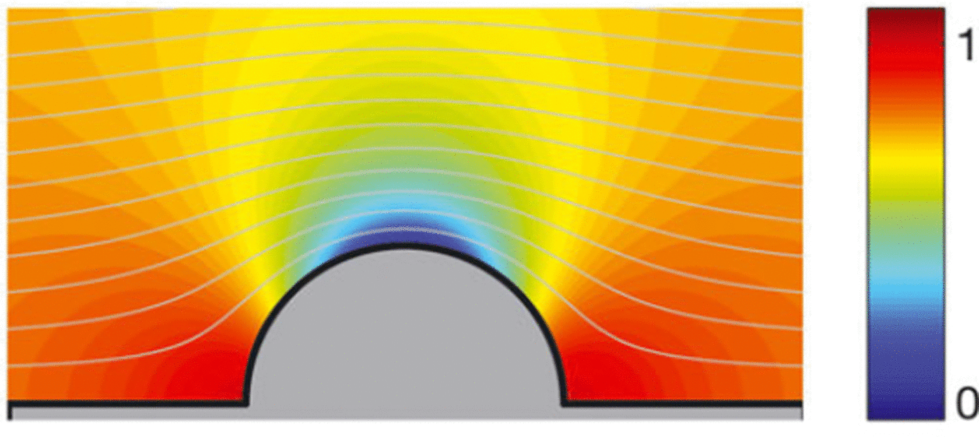
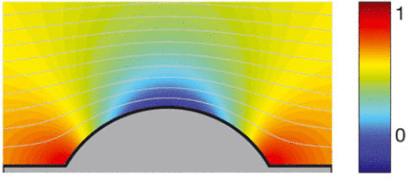
A simple model that can include the size and aspect ratio of the flow and which allows analytic calculations is to assume that the snow-air currents take the shape of an ellipse. The head of the snow-air flow is represented by half of the ellipse in the stationary frame, illustrated in Figure 4.
The inviscid, irrotational flow field around an ellipse with aspect ratio κ = 0.5. Streamlines (contours of ψ) are shown in grey and the pressure field is shown by the colour map scaled by the stagnation pressure.
The snow-air currents reach sufficiently high Reynolds numbers such that the influence of the chute surface on the flow will be confined to a narrow boundary layer and can therefore be neglected. The chute surface is therefore represented by the stagnation streamline. Fitting the air-pressure data to the pressure field around an ellipse will allow us to find the parameters that determine the ellipse field: the flow speed, height and aspect ratio. A further advantage of modelling the airflow around this elliptical geometry is that the airflow model can be directly coupled with the KSB integral model (Reference AnceyAncey, 2004; Reference Turnbull, McElwaine and AnceyTurnbull and others, 2007). This is discussed in more detail in section 5.
The steady inviscid incompressible flow around an ellipse with constant speed 1, of radius 1 in the flow direction x and height equal to its aspect ratio K in the orthogonal y direction is described by the complex potential
where z = x + iy, ϕ = Re w is the velocity potential and ψ = Im w is the stream function. Care is required in selecting the correct root to describe the problem, with symmetry dictated by the floor. The surface of the ellipse is described by the implicit equation
The ellipse area in the upper half-plane is κπ/2.
The modulus of the complex derivative describes the complete velocity field

This appears to be singular when K = 1, but the singularity is removable since we can rewrite the derivative as
This second form is more suitable for computation, but the previous form is used in subsequent calculations since its manipulation is clearer.
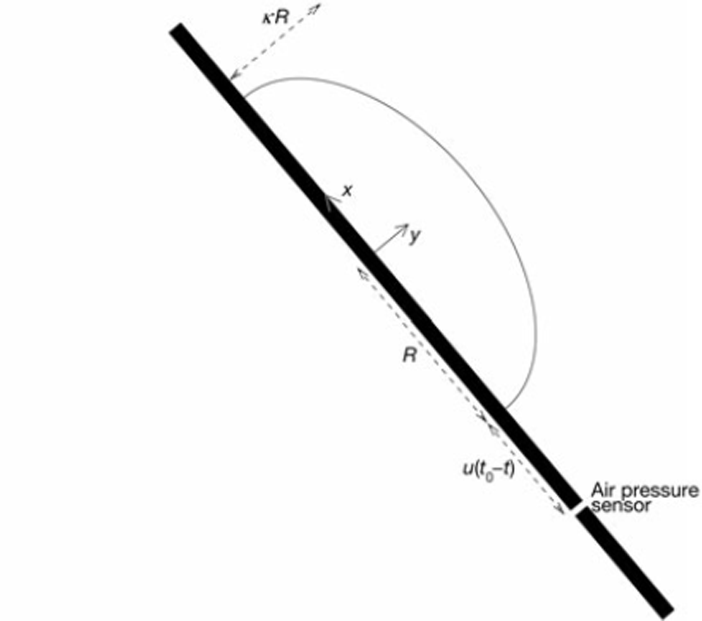
In our experiments the flow, modelled by the ellipse, travels past a stationary pressure sensor with speed u. This sensor is mounted on the centre line of the chute surface corresponding to the x axis, i.e. z = x. At the sensor, dw/dz is the flow velocity along the x axis. If t 0 is the time where the nose reaches the sensor, then at any time t the centre of the flow has position z = 1 + u(t0 - t)/R relative to the sensor (Fig. 5).
An ellipse of x radius R and aspect ratio κ approaching the air-pressure sensor at a constant speed u. Snapshot at time t where t < t 0.
From Bernoulli’s theorem, the measured dimensional pressure p will be the difference between the stagnation pressure ρ0 = ρu2/2 and the dynamic pressure ρ/2[u(dw/dz)]2, i.e.
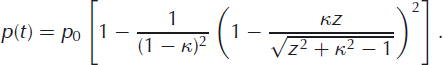
This provides the time history of the pressure field in terms of the flow speed u, its x radius R, aspect ratio K and the air density p outside the avalanche.
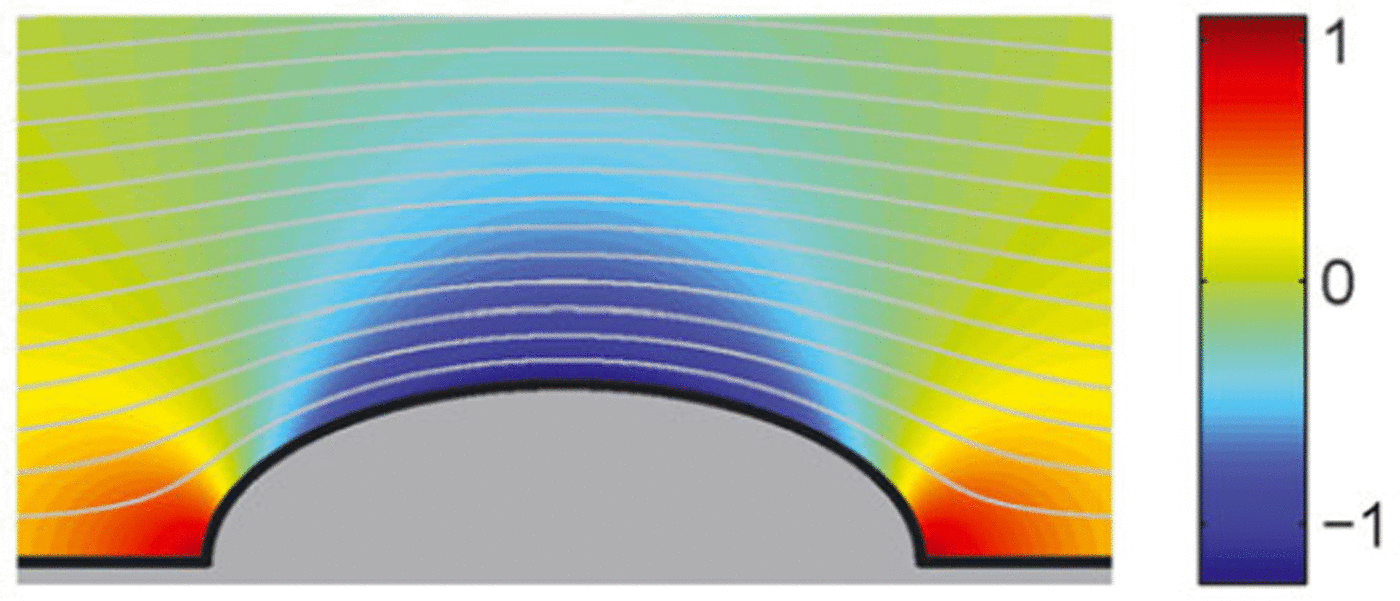
An ellipse of aspect ratio K = 1 is simply a circle. In the limit as K → 1, w(z) = z + 1/z. This limit reproduces the complex potential for the flow field around a semicircular disc (Fig. 6), which is the 2-D form of the dipole solution described in Reference McElwaine, Nishimura, McCaffrey, Kneller and PeakallMcElwaine and Nishimura (2001) and Reference McElwaine and TurnbullMcElwaine and Turnbull (2005).
Flow field around a disc. This is equivalent to the flow field around an ellipse of aspect ratio κ = 1, or flow around a dome with angle α = 2.
The asymptotic expansion for the ellipse flow complex potential (Equation (1)) tells us about the flow far away from the stagnation point, where z ≫ 1. This expansion is
Here we can see a recurring term that can be interpreted as an effective aerodynamic dipole radius ![]() The expansion can be rescaled by letting w*(z) = w(R*z)/R* so that terms of O(z–1) are scaled by R*-2 and terms O(z–3) are scaled by R*-4. This results in the scaled expansion
The expansion can be rescaled by letting w*(z) = w(R*z)/R* so that terms of O(z–1) are scaled by R*-2 and terms O(z–3) are scaled by R*-4. This results in the scaled expansion
This shows how aspect ratios different from 1 can be observed in the pressure signal as higher multipole terms. A benefit of scaling with the aerodynamic radius in this way is that the behaviour of the flow at small aspect ratios becomes apparent. In particular, the small aspect ratio K can have a very large effect on the flow field far from the stagnation point (large z). The radii of the ellipse with dipole radius 1 ![]() are
are ![]() so that the area of the scaled ellipse is 2π/(K + 1).
so that the area of the scaled ellipse is 2π/(K + 1).
4.2. Potential flow around a 60° dome
The ellipse model is useful for showing how the aspect ratio of the flow influences the observed pressure. However, it does not accurately represent the flow close to the front. Near the stagnation point at the nose (that is, as z → R) the ellipse pressure signal from Equation (5) takes the form p pρ - c(t - t0)2, where c is a constant that includes the stagnation pressure p0 and aspect ratio K.
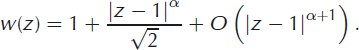
However, Reference McElwaineMcElwaine (2005) showed that the pressure close to the stagnation point should vary as p0 - c'|t – t0|. Reference McElwaineMcElwaine (2005) also showed that the front of a gravity flow always makes an angle of 60° to the surface it flows on (independent of slope angle or internal motion) and that the non-dimensional front velocity (or Froude number) is always ![]() These results extend earlier analyses of Reference Von Kármánvon Karman (1940) and Reference BenjaminBenjamin (1968) to flows down surfaces at arbitrary slope angles and with any degree of internal motion.
These results extend earlier analyses of Reference Von Kármánvon Karman (1940) and Reference BenjaminBenjamin (1968) to flows down surfaces at arbitrary slope angles and with any degree of internal motion.
The flow field is found from a series solution close to the stagnation point at the nose. Given this finding, it is helpful to assume that the shape of the flow makes an angle of 60° to the chute surface. If no flow separation occurred, the flow would be symmetric and there would be a rear stagnation point also with an angle of 60°. This is unlikely at the high Reynolds numbers of our experiments, however, where we expect separation and a turbulent wake. What happens at the rear of the body has little influence on the front and this assumption can correctly model the pressure in the vicinity of the front.
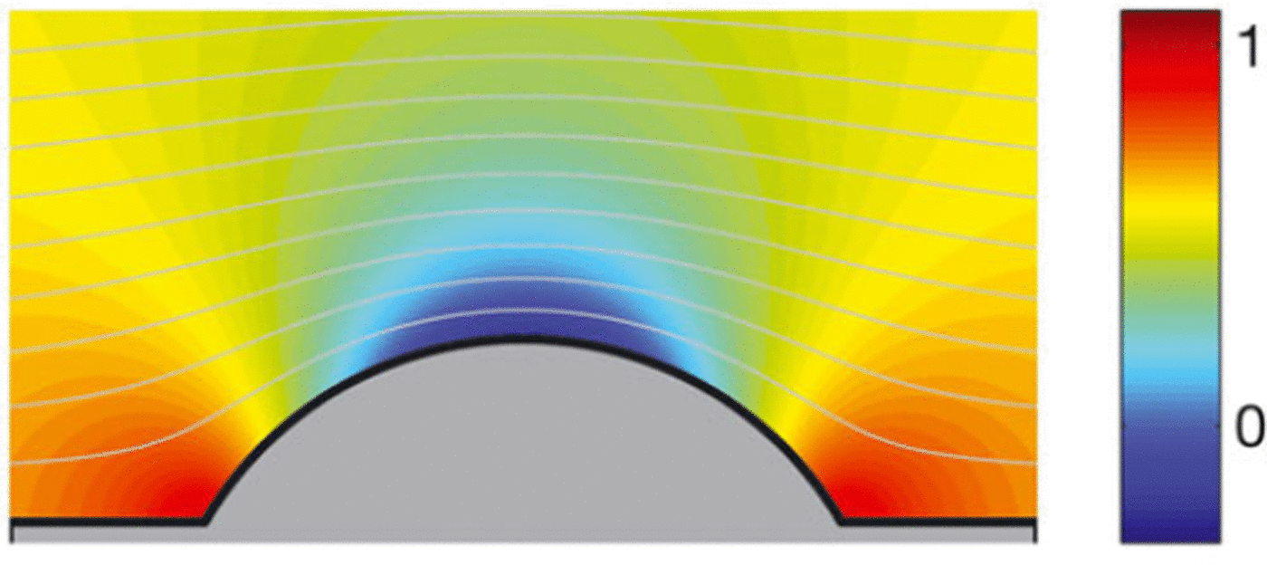
The shape we describe here as a ‘60° dome’ is part of the circle formed by the ends of the arc subtending angles of 60° to their chord, which is the chute surface. For generality we first consider a dome with arbitrary front angle a.
Consider the complex potential
with a branch cut between -1 and 1. This corresponds to a flow for y > 0 exterior to the circle of centre x = 0, y = cot(π/a) and radius 1/sin(π/a), with surface described by
If a = 3/2, this corresponds to the flow around an object with a front angle of 60° and a fixed aspect ratio, i.e. ![]() as shown in Figure 7. a = 2 reduces to the case of flow around a disc of the same geometry as the ellipse w ith K = 1.
as shown in Figure 7. a = 2 reduces to the case of flow around a disc of the same geometry as the ellipse w ith K = 1.
To consider the flow far away from the stagnation point, we write the asymptotic expansion as
Flow field around a 60• dome, where α = 3/2.
which is an odd function of z reflecting the forward-backward symmetry. The expansion shows that the complex potential corresponds to a flow of velocity u = 1/α at infinity with an effective aerodynamic dipole radius ![]() As for the ellipse case, we substitute variables such that w*(z) = αw(zR*)/R* so that
As for the ellipse case, we substitute variables such that w*(z) = αw(zR*)/R* so that
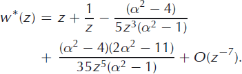
For the 60° dome where a = 3/2, we have
The flow field can be related to the inviscid wedge flow described in Reference McElwaineMcElwaine (2005) by considering the behaviour close to the stagnation point. Expanding the complex potential (Equation (8)) about the stagnation point at z = 1 for a general angle a,
The wedge-type nature of the flow for a = 3/2 can now be seen since
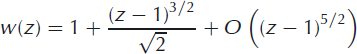
is the complex potential for a wedge flow with angle 60°.
The key difference from the ellipse or disc flows is that the pressure gradient does not tend to zero as the front is approached, since from Bernoulli
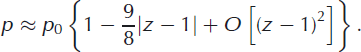
That is, the pressure distribution for the 60• dome exhibits a sharp point at the pressure maximum whereas it is rounded for the ellipse or disc models. We therefore expect the dome model to better fit the pressure near the maximum because it models the angle at the nose correctly. We expect the model to show a poorer fit in the medium field where the aspect ratio becomes important.
4.3. Non-dimensionalization
It is necessary to non-dimensionalize our measured data to allow comparison between flows of different sizes. We define a characteristic length scale for the flow that depends on the mass of snow in a flow measured at the base of the chute, M:

where ρs is the bulk snow density (~200kg m-3) and λ is the chute width. We also define a speed scale
where g is the acceleration due to gravity. Scaling measured and fitted lengths (e.g. the x radius R) with this characteristic length scale gives non-dimensional lengths (e.g. ![]() ) that are independent of the size of the flow. Similarly, the non-dimensional flow speed
) that are independent of the size of the flow. Similarly, the non-dimensional flow speed ![]() is independent of flow size.
is independent of flow size.
4.4. Fit results
The chute air-pressure data typically show a maximum when the flow front arrives at the sensor (Fig. 3), followed by a minimum inside the flow head. We fit the data with the ellipse, disc and 60° dome flow fields up to the pressure maximum at the flow nose (t0 = 0). The fit procedure minimizes the mean-square residuals between the fit prediction and the data for the non-dimensional parameters speed ![]() and x radius
and x radius ![]() and, in the case of the ellipse, the aspect ratio K.
and, in the case of the ellipse, the aspect ratio K.
A typical ellipse fit is shown with the raw air-pressure data in Figure 8. To analyse the dataset, the fit parameters for all of the flows were scaled with the characteristic length scale or velocity scale as defined by Equations (16) and (17), respectively.
(a) Entire air-pressure history and (b) pressure history close to the front of 100 mL snow–air flow on a 50° slope (grey curve: raw data; black curve: ellipse fit). The disc and 60° dome fits are not appreciably different in this presentation.
Aspect ratio is a non-dimensional quantity independent of flow size; this quantity does not require scaling to allow comparison between flows of different sizes. These scaled data of ellipse velocity and aspect ratio are shown for all flows versus slope angle in Figure 9. In these plots, the marker gives the mean value of the variable at each slope angle and the error bar has length ± one standard deviation. Particularly for the ellipse fit, the velocity data convincingly show a constant value for all slope angles as expected for inclined classical gravity flows (Reference Britter and LindenBritter and Linden, 1980; Reference Turnbull and McElwaineTurnbull and McElwaine, 2008).
(a) Scaled ellipse velocity independent of slope angle with mean value 0.36 and (b) ellipse aspect ratio versus slope angle with fitted curve κ = 0.24 tan 0.

The scaled ellipse radius gently decreases with increasing slope angle until the slope is vertical and the flow becomes significantly longer. The aspect ratio has a stronger increasing trend with slope angle, similar to the trend of flow heights seen in the video data (Reference Turnbull and McElwaineTurnbull and McElwaine, 2008). The aspect ratio predictions are good; for example, the flows in the still photographs in Figure 2 show aspect ratios close to those predicted by the ellipse fits. It is interesting to note that the ellipse fits predict an aspect ratio of K = 1, corresponding to the disc at a slope angle close to 85°. This would suggest that the disc is a good approximation at very high slope angles, corresponding to fully suspended snow-air flows.
The 60° dome geometry has a fixed aspect ratio of ![]() and thus the same number of fit parameters as the disc fit, i.e. one fewer than the ellipse solution. The dome fit predicts the maximum pressure well and shows a good agreement with the raw data. The normalized mean residual of the fit for all of the flows is 2.1%, showing that this 60° dome geometry captures the flow better than the disc’s semicircular geometry (mean normalized residual 2.6%). However, with one fewer fit parameter, the dome fit does not achieve such a close match to the raw data as the ellipse fit (mean normalized residual 1.6%). The aspect ratio of the dome model
and thus the same number of fit parameters as the disc fit, i.e. one fewer than the ellipse solution. The dome fit predicts the maximum pressure well and shows a good agreement with the raw data. The normalized mean residual of the fit for all of the flows is 2.1%, showing that this 60° dome geometry captures the flow better than the disc’s semicircular geometry (mean normalized residual 2.6%). However, with one fewer fit parameter, the dome fit does not achieve such a close match to the raw data as the ellipse fit (mean normalized residual 1.6%). The aspect ratio of the dome model ![]() is close to that of the ellipse fits at slope angles between 60° and 80°, explaining the good agreement over most of the experimental range.
is close to that of the ellipse fits at slope angles between 60° and 80°, explaining the good agreement over most of the experimental range.
4.5. Video measurements
The results of the video measurements were disappointing and it is difficult to draw convincing conclusions. The problem is that, despite the sieve, there were a number of larger particles of snow and ice. These move down the slope with higher velocity and make the edge of the flows poorly defined. For this reason we only briefly mention the video data.
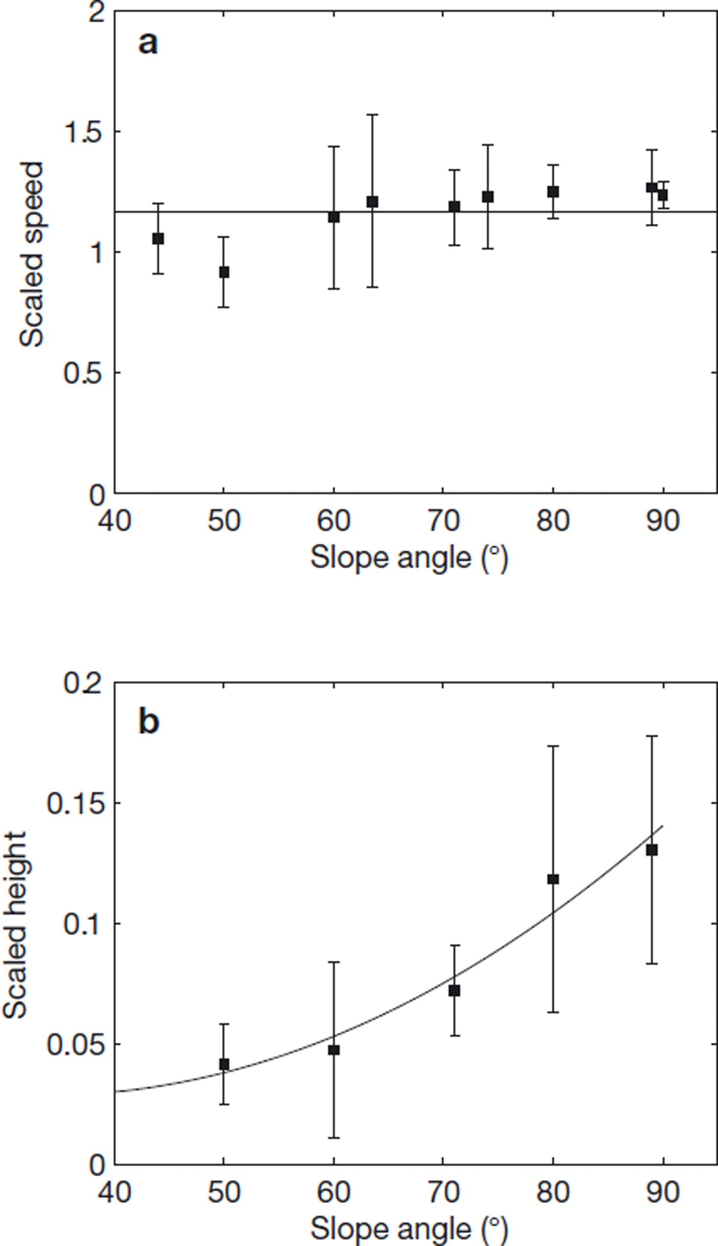
Figure 10 shows the non-dimensionalized speeds and heights as functions of slope angle. The scaling with avalanche size has collapsed the data and the speeds are roughly independent of slope angle in agreement with Reference Britter and LindenBritter and Linden (1980). They are considerably larger than the speeds inferred from the pressure measurements, however. The height measurements are particularly uncertain due to the diffuse nature of the upper surface and rear of the flows. There is a clear increase in height with slope angle, showing the transition to suspension. These data are in agreement with those presented in Reference Turnbull and McElwaineTurnbull and McElwaine (2008).
From the video measurements: (a) scaled flow velocities with mean value 1.2 and (b) scaled flow heights versus slope angle with fitted curve κ = 0.0014 tan 0 + 0.054.
4.6. Comparison
The ellipse model would be expected to give the best agreement over most of the range due to the extra fitting parameter (aspect ratio) which influences the signal over a significant range. The disc model (dipole only expansion) systematically under-predicts the maximum pressure. Despite having one fewer fit parameter than the ellipse model (this causes the additional scatter), the 60• dome predicts the maximum velocities very well (Fig. 11). This is because the 60• dome has a sharp pressure peak at the stagnation point rather than a rounded peak.
Difference between pressure prediction and actual measured pressure for a 100 mL snow–air flow on a 50• slope (black: 60° dome fit; mid-grey: ellipse fit; light grey: disc fit).
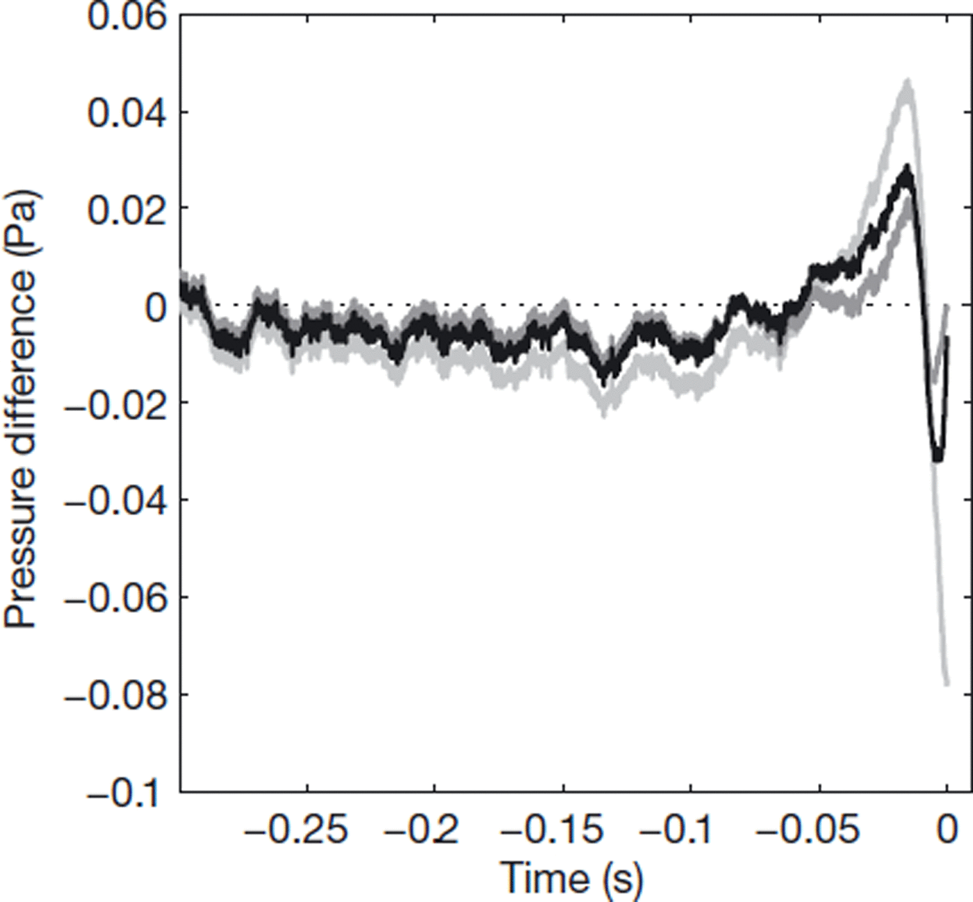
The additional parameter of aspect ratio κ significantly improves the fit and better predicts the pressure maximum.
This improved fit is demonstrated by the mean residual, normalized with the maximum pressure, for all of the flows. For the disc fit this mean normalized residual is 2.6% compared to 1.6% for the ellipse fit.
There are marked differences between the front velocities calculated from the video measurements and those calculated from the maximum pressure. They correlate (coefficient 70%) but there is a large degree of scatter, and the flow speeds derived from the video sequences are nearly three times greater than those measured by the pressure sensor.
There are several reasons why the pressure sensor records lower velocities. Figure 2 shows that the flow nose is raised above the chute surface, due to the no-slip condition at the chute surface (Reference SimpsonSimpson, 1997). The front stagnation point is actually between the point where the flow attaches to the surface and the raised nose, and the pressure sensor therefore passes below the stagnation point. The sensor is therefore not recording the actual maximum stagnation pressure, but a pressure that can be significantly lower. The pressure maps in Figures 4, 6 and 7 show how quickly the pressure decreases from the stagnation point. Furthermore, the flow noses often pass to one side of the sensor and the stagnation point can also be missed in the lateral direction.
A comparison between the pressure and video measurements is also complicated by the inhomogeneities in the flow. Larger clumps of snow mix with the ambient air less well than smaller particles, leading to wide variations in velocities within the flow. Video measurements track the front, which can comprise fast-moving clumps rather than the suspended fine material. Even homogeneous flows show front instabilities (Reference Nohguchi and OzawaNohguchi and Ozawa, 2009); the inhomogeneous snow flows are therefore difficult to track reproducibly. The pressure field, in contrast, is an integral measurement over the whole flow in the flow field and these inhomogeneities have less effect on the measurements.
5. KSB Integral Model
The KSB model solves volume, buoyancy and momentum equations for an avalanche flow at any slope angle or density ratio, incorporating well-verified entrainment assumptions for both ambient fluid and particles from the bed (Reference AnceyAncey, 2004; Reference Turnbull, McElwaine and AnceyTurnbull and others, 2007). These equations are solved for a prescribed geometry of a semi-ellipse with unit width, height h, length l, aspect ratio k = h/l and bulk density p. The equations can be rigorously derived from continuum theory (Reference Turnbull, McElwaine and AnceyTurnbull and others, 2007) and no additional closure assumptions or parameterizations are needed. It has been shown that the KSB equations successfully predict the front speeds of powder-snow avalanches (measured at the Swiss avalanche test site at Vallée de la Sionne) where the drag is dominated by the inertia of entrained snow and air and basal friction and aerodynamics drag are relatively insignificant (Reference Turnbull, McElwaine and AnceyTurnbull and others, 2007).
In this section we consider how the KSB model can be applied to the chute snow-air currents. There are two main differences between the chute currents and the field-scale avalanches previously modelled using the KSB equations. In the chute experiment, there is no snow entrainment from the lower surface. Furthermore, the sedimentation velocity of the particles is significant compared to the front velocity of the current and therefore plays a role in the dynamics which must be considered.
A volume equation is derived using an overall Richardson number dependent on air entrainment function (Reference TurnerTurner, 1973)
The entrainment of air leads to a volume flux of air into the cloud
where the function f is a two-part function fitted from the experiments of Reference Beghin, Hopfinger and BritterBeghin and others (1981)
where A = 1.6. A function for the aspect ratio k in terms of the slope angle 9 in radians was found from the same experiments:
where 71 = 0.002155, 72 = 0.0732 and 73 = 0.3. The sedimentation of snow on the upper surface leads to an effective detrainment of air
for the elliptic geometry at slope angle 9, where us ∼ 0.5 ms∼1 is the vertical settling velocity and ps is the density of snow (∼200 kg m−3). The factor (1 –ρ/ρs) hinders the settling velocity and is the simplest choice to ensure that p is always greater than ρs.
To simplify the following, we introduce a velocity uh = (1 – ρ/ρs)us. More realistic (or better verified) choices could easily be used. The total volume flux is therefore
Alternatively, we can change variables to the slopewise coordinate s using d/dt = ud/ds, i.e.
The buoyancy of the current is defined B = (ρ – ρa)V. Although particle sedimentation leads to a change in cloud geometry, the depositing particles are still contained within the cloud and the buoyancy is maintained. We therefore have
with no snow entrainment.
The momentum equation is finally derived, assuming negligible basal friction or aerodynamic form drag. This may be true at the high Reynolds numbers found in real powder-snow avalanches (of the order 107–109) (Reference Hogg and WoodsHogg and Woods, 2001), but the validity of the assumption may not be strong for the chute flows with lower Reynolds numbers (of the order 104) where the viscous boundary layers form a greater proportion of the depth of the current and where no snow is entrained, reducing the inertial entrainment drag. Nevertheless, air entrainment into the current is significant and the underlying assumption is that acceleration of the entrained air and the air flowing around the current is the dominant drag mechanism.
Following Reference BatchelorBatchelor (1967), an added mass coefficient χ is introduced to account for the motion of the air flowing around the current. It is shown in Reference Turnbull, McElwaine and AnceyTurnbull and others (2007) that the added mass coefficient for an ellipse is equal to the aspect ratio χ = k. The total inertial mass of the current can therefore be written
By Newton’s second law, the rate of change of momentum dMu/dt is equal to the downslope component of gravity Bg sin θ. Thus
or, in terms of the slopewise coordinate,
The rearrangement of the momentum equation in terms of the velocity u is unwieldy, so will not be given here (see Reference Turnbull, McElwaine and AnceyTurnbull and others 2007). An additional consideration for flows such as those on the chute with particle sedimentation is that a term — (qs+qa)ρa u arises in the momentum equation. The positive qa therefore acts to decelerate the current. For flows with sedimentation, however, the negative qs accelerates the current. We assume that particle momentum is permanently transferred from the suspension to the ambient air as particle sediment from the surface; therefore qsρa u = 0 in the momentum equation.
The volume, density and momentum equations (Equations (24), (25) and (28)) were solved numerically using a Runge-Kutta scheme for the chute geometry for each slope angle and volume released, subject to initial conditions. The currents were given an initial speed at the exit of the drop tube of 1 m s−1 and an initial density of 100 kg m−3, since the snow had spread out to some degree through the drop tube and sieve. The initial current volume was the volume of snow in the beaker initially released, multiplied by 2 to account for the reduced density after the drop tube. The model results do not vary significantly with changes to these initial values.
5.1. Results
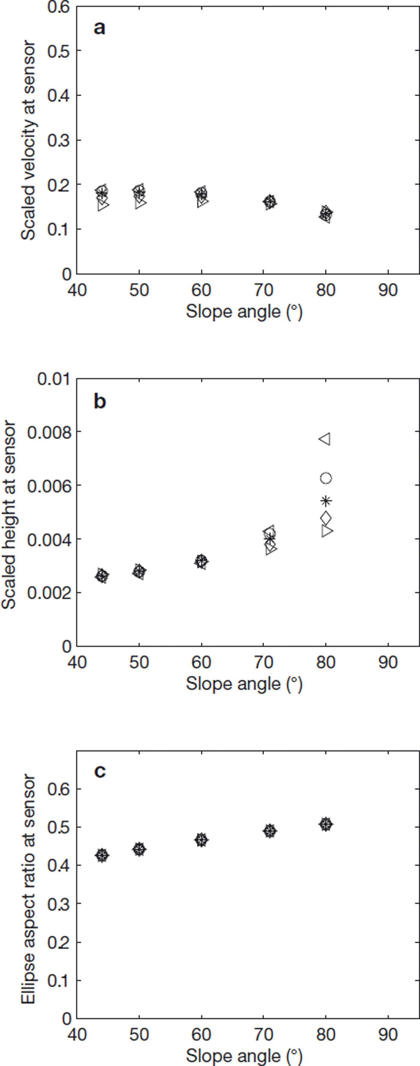
For each volume released and at each chute slope angle the KSB model gives the current trajectory and geometry. The results were scaled by a length scale ![]() where Vi is the release volume and 0.2 m is the chute width (this scaling is equivalent to that used for the potential flow model fits and the video measurements). The corresponding speed scale is
where Vi is the release volume and 0.2 m is the chute width (this scaling is equivalent to that used for the potential flow model fits and the video measurements). The corresponding speed scale is ![]() The current speeds and heights predicted by the KSB model are depicted in Figure 12 for each slope angle and volume. The scaled velocities agree well with the values found from the ellipse fitting. The heights and aspect ratio, although showing a similar trend, return smaller values than the fit results or video measurements.
The current speeds and heights predicted by the KSB model are depicted in Figure 12 for each slope angle and volume. The scaled velocities agree well with the values found from the ellipse fitting. The heights and aspect ratio, although showing a similar trend, return smaller values than the fit results or video measurements.
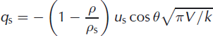
Scaled KSB current (a) velocities, (b) heights and (c) aspect ratios at the position of the air-pressure sensor versus slope angle.
6. Conclusions
We have taken air-pressure measurements from suspension flows for a wide range of slope angles and release volumes and shown how these measurements can be used to infer avalanche size, speed, aspect ratio and front angle. These measurements have qualitatively similar features to those from natural avalanches, showing large-scale motion within the flows. This internal motion, when at the scale of an avalanche, will generate larger shear stresses than the direct impact force given by the stagnation pressure of the flow. This could potentially give rise to greater damage than traditionally calculated.
Despite our best efforts to perform accurate and reproducible experiments, the data have many uncertainties and errors. These are primarily due to the inhomogeneities in the snow that cause large variations in the size, shape and speed of the initial flow and also variations down the slope. Future work to enable more quantitative comparison with dynamic models would be best completed with other materials.
Acknowledgements
We thank the technical staff at the Swiss Federal Institute for Snow and Avalanche Research (SLF) for the construction of the chute. J.N.M. was supported by the Engineering and Physical Sciences Research Council (EPSRC) and the Royal Society.


