


1 Introduction
High-power yellow–orange lasers (565–595 nm) have significant applications across diverse fields, including astronomy, photoacoustic microscopy and biomedicine[ Reference Sun, Yang, Li, Zeng, Jiang and Feng 1 – Reference Maslov, Zhang, Hu and Wang 5 ]. For example, 589 nm lasers are employed in sodium guide star systems to correct atmospheric wavefront distortion via adaptive optics technology[ Reference Yang, Kitzler, Spence, Bai, Feng and Mildren 6 ]. Similarly, 595 nm orange lasers with high pulse energies are widely used for photothermal therapy of skin conditions such as nevus flammeus, telangiectasia and angioma warts[ Reference Turkmen, Altunisik and Sener 7 – Reference Garden, Tan and Parrish 9 ]. Consequently, the development of high-power yellow and orange laser sources is of great interest, as these coherent light sources at previously inaccessible wavelengths could enable new breakthroughs in materials science and optical engineering[ Reference Qi, Huo, Bai, Zhang, Chen, Ding, Wang and Lu 10 , Reference Cai, Yuan, Fang, Lin and Xu 11 ].
Direct diode lasers in the yellow–orange range face severe limitations due to semiconductor band structure constraints. To date, the highest output power from a semiconductor laser in this range is 220 mW at 582 nm using AlGaInP/InGaP quantum wells[ Reference Bohdan, Bercha, Trzeciakowski, Dybała, Piechal, Sanayeh, Reufer and Brick 12 ]. Alternative approaches to generating yellow–orange light include optically pumped dye lasers and diode-pumped solid-state lasers (DPSSLs). Dye lasers can deliver high pulse energies and broad wavelength tunability, but they suffer from complex setups and potential dye toxicity[ Reference Garden, Tan and Parrish 9 ]. DPSSLs, in contrast, offer compact designs and high beam quality, making them a promising route for high-power operation. However, scaling the power of DPSSLs in the yellow–orange range remains challenging, particularly for integrated and miniaturized systems.
For example, blue diode-pumped Tb3+/Dy3+-doped crystals can emit yellow lasers[ Reference Luo, Gu, Tang, Geng, Li and Cai 13 – Reference Ding, Li, Zhang and Liu 15 ], but due to the spin-forbidden electronic transitions of Dy3+, their absorption cross-section is very small (~10–21 cm2), limiting the highest laser output at 581 nm to 628 mW[ Reference Huang, Gong, Zhang, Lin, Zhang, Teng, Li and Sun 16 ]. More recently, a continuous-wave (CW) yellow laser at 587 nm exceeding 1 W was achieved with a vertical external cavity surface emitting laser using intracavity second-harmonic generation (VECSEL-SHG)-pumped terbium-doped lithium yttrium fluoride (Tb:YLF) crystal[ Reference Kotov, Kaneda, Püschel, Tanaka, Hair, Nehrir and Temyanko 17 ]. Another widely used method, frequency doubling in DPSSLs (2ω-DPSSLs), has produced high-power visible lasers – such as green sources exceeding 1 kW[ Reference Zhou, Wang, Chen, Yu and Xu 18 ]. However, in the yellow–orange region, power scaling becomes exponentially more difficult due to the near-zero fluorescence emission cross-section around 1130–1190 nm in conventional Nd3+- and Yb3+-doped crystals[ Reference Di, Sai, Sun, Xu, Kong, Xie, Liu, Teng and Zhu 19 – Reference Gao, Lv, Zhu, Wang, You, Li, Xu, Wang and Tu 21 ]. In order to solve these problems, some indirect nonlinear optical technologies were developed, including sum-frequency generation[ Reference Bian, Bo, Zuo, Yuan, Chen, Peng and Xu 22 ], stimulated Raman laser[ Reference Jiang, Ding, Guo, Zhang, Qi, Shang, Song, Wang, Wang, Liu, Yao, Ni and Yao 23 – Reference Huang, Chang, Hsieh, Li and Chen 27 ], etc. Despite substantial power improvement, these yellow–orange laser devices suffer from complex optical design, large volume and high cost. Therefore, there is an urgent demand for the development of compact, low-cost and high-power yellow–orange DPSSL sources.
A promising strategy is to create efficient gain transitions directly at 565–595 nm or their corresponding infrared fundamental wavelengths (FWs; 1130–1190 nm). Recently, multi-phonon-assisted lasing involving electron-lattice energy exchange was proposed to modulate electronic transition processes, in which a CW lasing at 1130 and 1180 nm was realized in Yb3+-doped YCa4O(BO3)3 (Yb:YCOB) crystal[ Reference Liang, He, Lu, Fang, Fu, Yu, Zhang and Chen 28 , Reference Si, Liang, Lu, Yu, Zhang and Wu 29 ]. Due to their intrinsic frequency-doubling capability, Yb:YCOB crystals can also produce integrated yellow–orange output with relatively high powers. Previous CW laser experiments have achieved 8.7 W at 570 nm and 4.83 W at 590 nm[ Reference Si, Liang, Zhou, Lu, Yu, Zhang and Wu 30 , Reference Du, Lu, Liang, Chen, Yu and Zhang 31 ], suggesting the potential for further power scaling. However, the strong thermal effect hinders its further power improvement at CW operation.
In this work, we introduce a quasi-continuous-wave (QCW) pumping scheme to mitigate thermal effects and enhance multi-phonon-assisted laser performances. Using a microchip Yb:YCOB device, we achieved record QCW output peak powers of 125 W (565 nm yellow laser) and 102 W (590 nm orange laser). To the best of our knowledge, these results represent the highest peak powers reported for QCW yellow–orange emission from any all-solid-state microchip laser. Furthermore, we demonstrate that a QCW orange laser can efficiently excite the fluorescent dye Cyanine 3.5, producing a 20-fold enhancement in photoluminescence compared to traditional green laser excitation – highlighting its potential for flow cytometry and other bio-optical applications.
2 Simulation
Achieving high-power yellow–orange emission requires careful management of thermal effects[ Reference Badtke, Kalusniak, Püschel, Tanaka and Kränkel 32 ]. In conventional Yb:YCOB operation, the lasing wavelength lies in the 1020–1030 nm range, corresponding to a quantum defect of only 4.31%–5.24% under 976 nm pumping[ Reference Du, Chen, Yu and Zhang 33 ]. In contrast, multi-phonon-assisted lasing at 1130 and 1180 nm increases the quantum defect to 13.63% and 17.29%, respectively. This high quantum defect leads to substantial heat generation from non-radiative relaxation, which can degrade beam quality and compromise power stability. Excessive heat accumulation in the crystal also produces strong temperature gradients, resulting in significant changes to the thermally induced refractive index and to the phase-matching conditions required for efficient nonlinear frequency conversion[ Reference Badtke, Kalusniak, Püschel, Tanaka and Kränkel 32 ]. These effects reduce second-harmonic-generation (SHG) efficiency and impose strict limits on power scaling. Consequently, effective thermal management strategies are critical for realizing high-power yellow–orange lasers.
The temperature field distributions for yellow (565 nm) and orange (590 nm) laser emission in Yb:YCOB crystals were modelled using the finite element method[ Reference Yu, Pan, Pan, Chu, Chen and Li 34 ]. In the simulations, the pump source (λ = 976 nm) had a beam waist radius of 110 μm, and the crystal boundary temperature was fixed at 2°C. The Yb:YCOB crystal, with dimensions of 3 mm × 3 mm × 6 mm, is shown in the simulation coordinate system in Figure 1(a) and as a physical sample in Figure 1(d). The absorption coefficient of 15% (atomic fraction) Yb:YCOB was measured to be 2.7 cm–1 at 976 nm, and the thermal conductivity was 2.3 W/(m·K). Pump light was injected longitudinally along the crystal axis. Figures 1(b) and 1(c) show three-dimensional axial temperature profiles for the yellow and orange lasers, respectively. Thermal simulations indicate maximum temperatures at the incident end face of 314.6 K for the yellow laser and 328.4 K for the orange laser. The higher temperature in the orange case is attributed to stronger heat generation and accumulation from its larger quantum defect relative to the yellow emission.
(a) Yb:YCOB crystal model (3 mm × 3 mm × 6 mm) used in numerical simulations. (b) Three-dimensional temporal evolution of the axial temperature profile for the 1130 nm fundamental laser and its frequency-doubled yellow output at 565 nm. (c) Corresponding profiles for the 1180 nm fundamental laser and orange output at 590 nm. (d) Photograph of the Yb:YCOB crystal. (e) Simulated temperature distribution along the crystal length. (f) Temperature distribution across the incident-face cross-section. Simulations in (b)–(f) were performed at an average pump power of 5 W. (g) Transient temperature at the crystal front-face centre for different repetition frequencies (RFs). (h) Transient temperature for different pump pulse widths. (i) Steady-state temperature at the front-face centre as a function of the RF and pulse width; the white dashed arrow indicates the optimal low-duty-cycle regime. In these simulations, the pump power was set to 500 W.
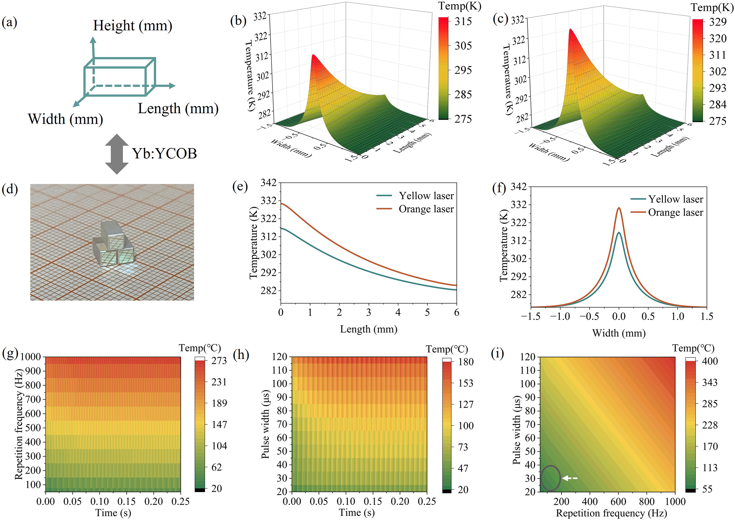
As illustrated in Figures 1(e) and 1(f), longitudinal temperature gradients extend from 328.4 to 275 K for the orange laser and from 314.6 to 275 K for the yellow laser, with the peak temperatures consistently located at the centre of the incident face. Such heat accumulation induces radial and tangential thermal stresses, which can severely degrade beam quality and reduce conversion efficiency. Therefore, achieving high-power yellow–orange lasers from Yb:YCOB crystals necessitates active thermal management to mitigate conversion efficiency reduction and avoid thermally induced deterioration of beam quality.
QCW pumping significantly reduces thermal accumulation in laser media by employing a periodic pulsed pump, which delivers high-power injection within short durations followed by sufficient thermal relaxation periods[ Reference Ding, Zeng, Wang, Wu, Wang, Zhang, Wang, Ning, Xi and Xu 35 ]. This approach operates through two coupled mechanisms: (i) time-partitioned excitation, where population inversion is established during pump pulses and dissipated during idle intervals; and (ii) thermal gradient control via precise adjustment of the pulse width and repetition frequency (RF)[ Reference Koechner 36 ]. Compared with CW diode pumping, QCW pumping offers superior thermal management by intermittently delivering pump energy, thereby reducing heat accumulation and mitigating thermal effects[ Reference Jiang, Xu, Chen, Zheng, Tong, Liu, Ruan, Wang, Su and Gao 37 ].
We analyzed and simulated the thermal effects of high-power QCW pumping in the Yb:YCOB crystal. The heat generation term Q(ξ, t) can be described by Equation (1):
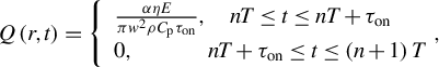 $$\begin{align}Q\left(r,t\right)=\left\{\begin{array}{l}\frac{\alpha \eta E}{\pi {w}^2\rho {C}_{\mathrm{p}}{\tau}_{\mathrm{on}}},\quad nT\le t\le nT+{\tau}_{\mathrm{on}}\\ {}0,\kern3.28em nT+{\tau}_{\mathrm{on}}\le t\le \left(n+1\right)T\end{array}\right.\!\!\! ,\end{align}$$
where ρ is the density and C p is the heat capacity. Here, α is the absorption coefficient of the crystal, r denotes the crystal length, t is time, τ on represents the turn-on duration, E is the pump pulse energy and w is the radius of the incident pump beam. The thermal load efficiency of the laser is η [ Reference Fan 38 ].
For the QCW yellow–orange Yb:YCOB laser with a pump beam radius w = 220 μm and an absorption coefficient α = 2.7 cm−1, the time-dependent temperature distribution u(r, t) can be derived using the appropriate Green’s function G(r, ξ, τ)[ Reference Barton 39 ] from Equation (2):
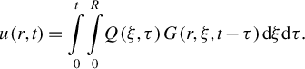 $$\begin{align}u\left(r,t\right)=\underset{0}{\overset{t}{\int }}\underset{0}{\overset{R}{\int }}Q\left(\xi, \tau \right)G\left(r,\xi, t-\tau \right) \mathrm{d}\xi \mathrm{d}\tau .\end{align}$$
The closed-form solution for the time-dependent temperature distribution u(r, t) on the pumped crystal surface can be derived by solving the inhomogeneous heat diffusion in Equation (3)[ Reference Carslaw and Jaeger 40 ]:
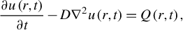 $$\begin{align}\frac{\partial u\left(r,t\right)}{\partial t}-D{\nabla}^2u\left(r,t\right)=Q\left(r,t\right),\end{align}$$
where D is the thermal diffusivity of the laser crystal. The resulting transient temperature distribution at the front surface of the Yb:YCOB crystal is shown in Figure 1. In QCW pumping, the pump duty cycle is adjusted by varying the RF and pulse width.
As shown in Figure 1(g), with the pulse width fixed at 20 μs, the transient temperature peaks at 272°C for a high RF of 1000 Hz, whereas at a low RF of 50 Hz it is only 50°C. In Figure 1(h), with the RF fixed at 50 Hz, the transient temperature reaches 179°C for a 120 μs pulse width and 60°C for a 20 μs pulse width. Notably, at low RFs of 50–200 Hz, the temperature remains below 100°C and, similarly, for narrow pulse widths of 20–60 μs, it also stays below 100°C. Figure 1(i) clearly demonstrates that combining low RFs with narrow pulse widths minimizes temperature rise in the laser crystal, thereby significantly mitigating thermal effects.
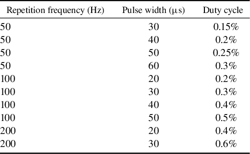
In addition, laser power is an important parameter for QCW-pumped lasers, which relies on the accumulated number of population inversions. The laser output power P out can be expressed as follows[ Reference Svelto 41 ]:
 $$\begin{align}{P}_{\mathrm{out}}=\frac{\gamma_2c}{2{L}_{\mathrm{e}}}\frac{V_{\mathrm{a}}{\tau}_{\mathrm{c}}{N}_0}{\tau } hv\left(\frac{P_{\mathrm{p}}}{P_{\mathrm{th}}}-1\right),\end{align}$$
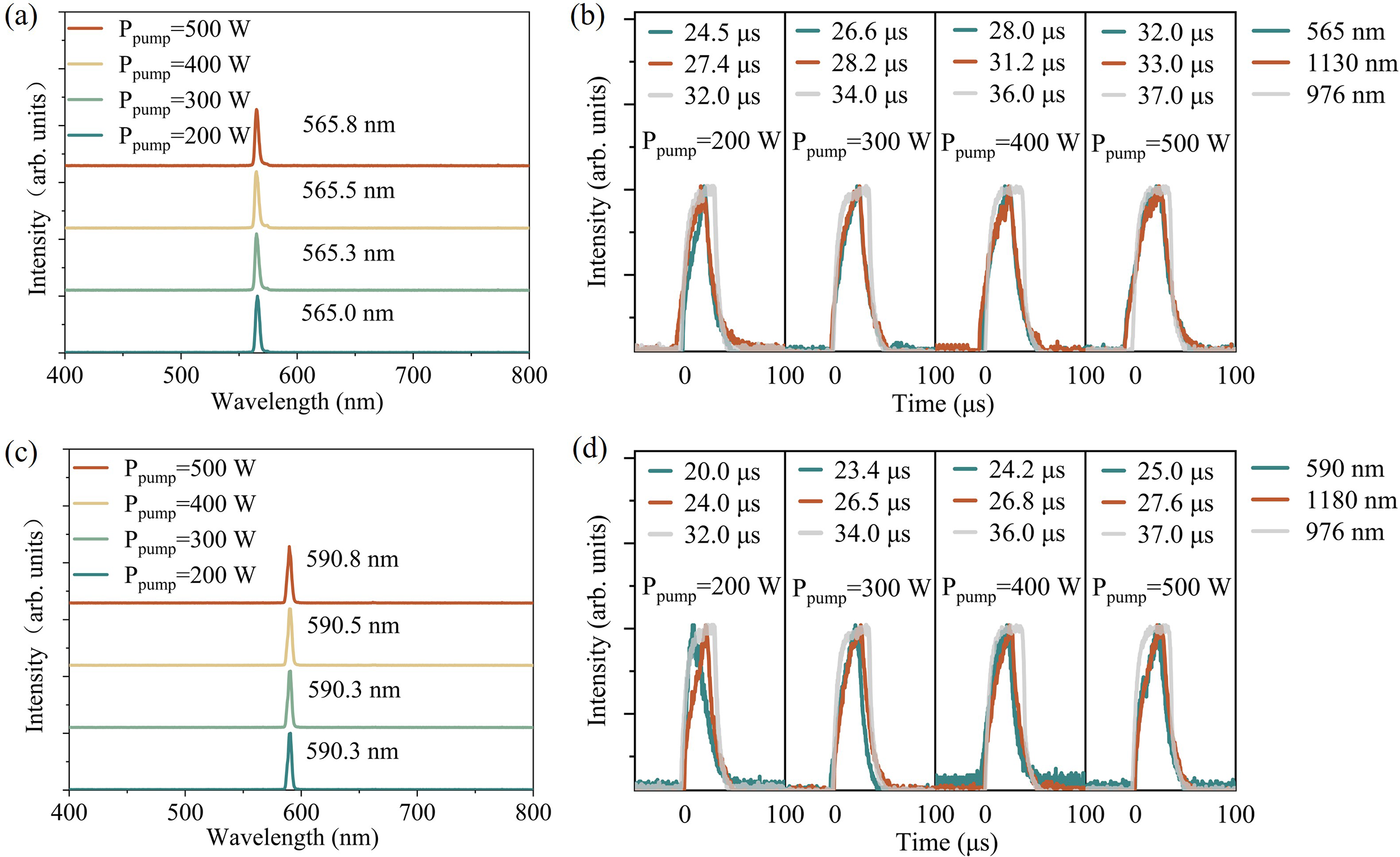
where γ2 represents the photon loss in the resonant cavity, V a represents the volume of the gain medium mode, c represents the speed of light, τ c represents the photon lifetime, N 0 represents the number of particles in the upper energy level, hv is the photon energy, L e represents the optical path of the resonant cavity, τ represents the lifetime of the upper energy level, P p represents the pump power absorbed by the gain medium and P th represents the threshold absorbed pump power. In QCW pumping setups, N 0 is determined by the pump duty cycles because the particles at the upper level are gradually relaxed owing to the finite energy level lifetimes. Here, ‘relaxed’ refers to spontaneous non-radiative relaxation accompanied by thermal phonon generation, without photon emission. If the pulse interval is too long, N 0 decreases substantially, leading to reduced laser power and efficiency. If the pulse width is too narrow, after each pulse ends, only a small number of ground state particles will jump up to the excited state by absorbing the pump light, failing to establish population inversion. For example, at 50 Hz (Δt = 20 ms), the pulse interval is considerably longer than at 100 Hz (Δt = 10 ms) or 200 Hz (Δt = 5 ms). Given the upper-level lifetime of Yb:YCOB (τ = 2.28 ms, T = 300 K[ Reference Zhang, Meng, Wang, Zhu, Liu, Cheng, Dawes, Dekker, Zhang and Sun 42 ]), a 50 Hz RF provides insufficient pump power to sustain high-power yellow–orange lasing. Therefore, QCW pumping parameters in the range of 100–200 Hz RF and 20–60 μs pulse widths are identified as optimal, simultaneously minimizing thermal accumulation and maximizing output power. The duty cycle values for different modulation frequencies are summarized in Table 1. We designed and performed the laser experiments based on these specific parameters.
The duty cycles corresponding to different modulation frequencies.

3 Experimental results and discussion
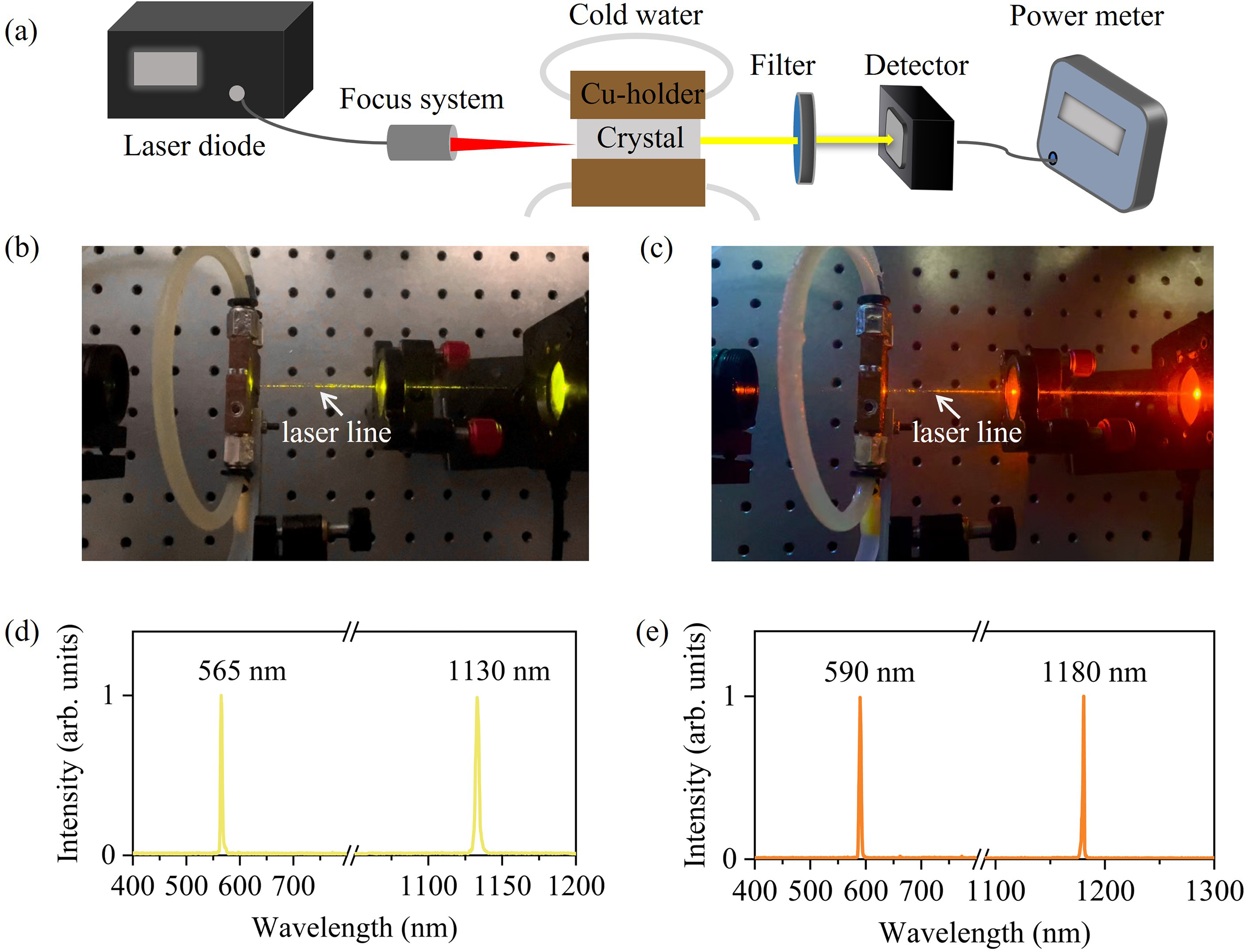
Figure 2(a) presents the schematic of the QCW yellow and orange laser systems. The pump source was a fibre-coupled InGaAs semiconductor laser with a central wavelength of 976 nm, a core diameter of 220 μm and a numerical aperture of 0.22. The pump beam was focused into the crystal using an imaging unit with beam compression ratios of 1:2 or 1:1, producing waist radii of 220 or 110 μm inside the crystal. According to the numerical calculations, the Rayleigh length of pump light is 38.95 mm. The pump beam waist was positioned at the centre of the laser crystal.
(a) Experimental configuration of the QCW yellow–orange lasers. (b) Photograph of the QCW yellow lasers at 565 nm. (c) Photograph of the QCW orange lasers at 590 nm. (d) Laser spectrum of the QCW fundamental-wave lasers and yellow lasers. (e) Laser spectrum of the QCW fundamental-wave lasers and orange laser.

The laser medium was a YCOB crystal doped with 15% (atomic fraction) Yb3+ ions, cut along type-I phase-matching directions of (θ = 113°, φ = 33°) for the yellow laser and (θ = 113°, φ = 31°) for the orange laser, respectively. The 3 mm × 3 mm front and end faces of the crystals were polished and coated. To dissipate waste heat during the laser operation, the Yb:YCOB crystal was wrapped in indium foil and mounted on a copper block. The water-cooling temperature was set to 2°C. The pump absorption ratio of Yb:YCOB crystal is 90.5% at the RF of 100 Hz and pulse width of 40 μs. Benefitting from the low thermo-optic coefficient and large temperature bandwidth, the thermally induced phase-mismatch in Yb:YCOB crystal could be neglected for QCW-pumped yellow–orange lasers.
Resonator coating design played a crucial role in enabling yellow–orange operation. In the yellow laser configuration, the front surface served as the input mirror, with high transmission at 950–1100 nm and high reflection at 1120–1150 and 550–590 nm. The end surface, acting as the output mirror, held high transmission at 550–590 nm and high reflection at 1120–1150 nm. This coating scheme suppressed conventional lasing near 1030 nm and 1080 nm while strongly amplifying multi-phonon-assisted lasing.
In the orange laser configuration, the front-surface coating exhibited high transmission at 950–1140 nm and high reflection at 1170–1190 and 585–595 nm. The end surface was highly reflective at 1170–1190 nm and transmissive at 1000–1140 and 585–595 nm. This design suppressed three-phonon-assisted lasing at 1130 nm, thus favouring efficient orange laser generation.
A filter with high transmission at 550–600 nm and high reflection at 976, 1130 and 1180 nm was placed after the Yb:YCOB crystal to block residual pump light and fundamental waves. Experimental photographs of the QCW yellow and orange lasers are shown in Figures 2(b) and 2(c). For the yellow laser, the FW and frequency-doubled wavelength were 1130 and 565 nm, respectively, in Figure 2(d). For the orange laser, the FW and frequency-doubled wavelength were 1180 and 590 nm, respectively, in Figure 2(e).
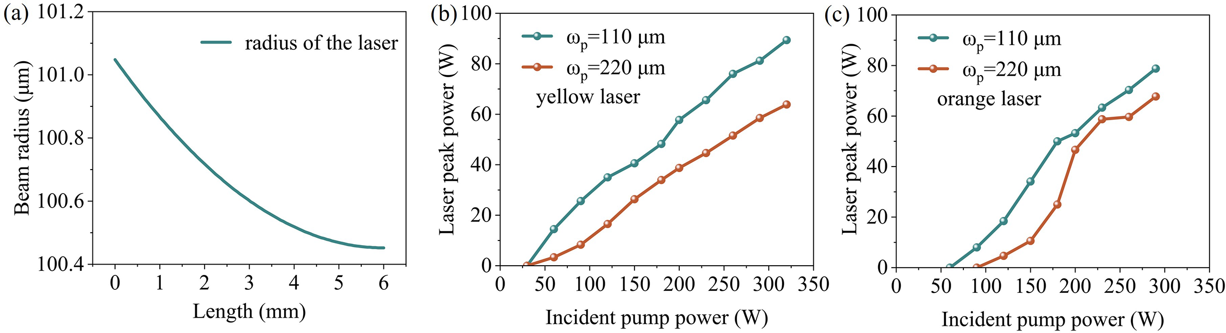
To optimize mode matching between the pump light and the laser mode, we first adjusted the pump beam spot size experimentally. Intracavity mode-matching calculations show that the laser spot radius decreases slightly from 101.05 to 100.45 μm as the crystal length increases from 1 to 6 mm (Figure 3(a)). This indicates that a pump beam radius of approximately 100 μm is optimal. For comparison, we tested pump beam radii of 110 and 220 μm.
(a) Spatial distribution of the pump and laser beam spot radii inside the crystal. (b) Peak power of QCW yellow lasers for different pump beam radii. (c) Peak power of QCW orange lasers for different pump beam radii. Notably, as the incident pump power increased from 100 to 500 W, the pump beam spot radius expanded from 110 to 116 μm.

As shown in Figure 3(b), for QCW yellow lasers, the 110 μm beam radius achieved a maximum peak power of 89 W – substantially higher than approximately 64 W obtained with the 220 μm beam. A similar trend was observed for QCW orange lasers (Figure 3(c)), where the 110 μm beam yielded a peak power of 79 W, compared with 68 W for the larger beam. Based on these results, all subsequent yellow and orange laser experiments employed the 110 μm pump beam configuration.
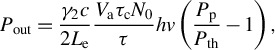
We conducted QCW-pumped yellow and orange laser experiments over a range of RFs and pulse widths. Figures 4(a)–4(f) present the output power and conversion efficiency of the yellow laser in Yb:YCOB crystals under different duty cycles. The highest performance was achieved at an RF of 100 Hz with a pulse width (τ) of 40 μs. Under these conditions, an incident peak power of 550 W yielded an average input power of 1.8 W. The maximum peak output power reached 125 W, corresponding to an optical-to-optical efficiency of 22.7%. The average output power was 0.4 W, with a single-pulse energy of 4 mJ. At an RF of 200 Hz and τ = 30 μs, the peak power and optical-to-optical efficiency were 97.9 W and 20.8%, respectively, producing an average power of 0.47 W and a single-pulse energy of 2.35 mJ. For 50 Hz and τ = 50 μs, the peak power was 108.2 W with 18.7% efficiency, yielding 0.16 W average power and 3.2 mJ single-pulse energy.
Laser performance of QCW yellow laser at different RFs: (a) 200 Hz; (b) 100 Hz; (c) 50 Hz. Optical-to-optical efficiency of QCW yellow laser at different RFs: (d) 200 Hz; (e) 100 Hz; (f) 50 Hz.
Peak powers at 100 Hz consistently exceeded those at 200 and 50 Hz. At 200 Hz, the shorter interpulse intervals limited thermal relaxation, causing heat accumulation that constrained peak power scaling. At 50 Hz, the longer pulse intervals allowed significant population inversion decay between pulses, reducing the excited-state population available for subsequent lasing. Although low RFs improve heat dissipation, they also underutilize the pump energy, lowering overall efficiency. Thus, 100 Hz provided the optimal balance between heat management and pump energy extraction[ Reference Guo, Ma and Shu 43 ].
In comparison, a QCW yellow laser based on a microchip Dy:Y3Al5O12 (Dy:YAG) crystal pumped by a blue diode achieved a maximum single-pulse energy of 0.3 mJ at 583 nm[ Reference Bowman, O’Connor and Condon 44 ]. Another Dy:YAG system at 582.7 nm reported 1.1 mJ per pulse[ Reference Ju, Shen, Yao, Chen, Tan, Liu, Luo, Zhang and Gao 45 ]. The Yb:YCOB yellow laser in this study achieved 4 mJ per pulse – representing 13.3 and 3.6 times improvements over these Dy:YAG systems, respectively – demonstrating its superior energy storage and thermal management capabilities.
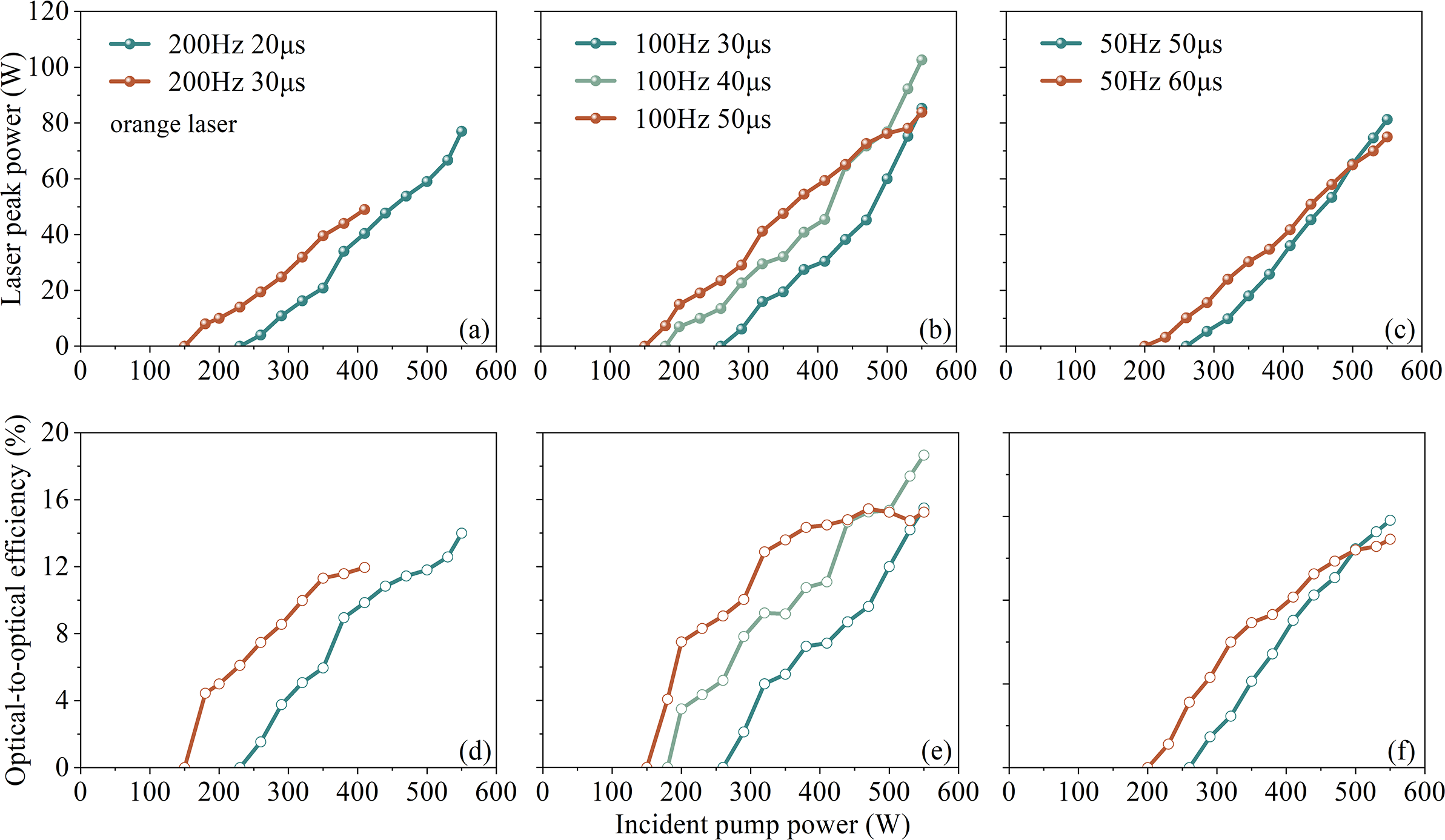
Figures 5(a)–5(f) illustrate the output power and optical-to-optical conversion efficiency of the Yb:YCOB orange lasers under varying duty cycles. At an RF of 200 Hz and a pulse width of 20 μs, the peak power and conversion efficiency reached 77 W and 14%, respectively, with an average output power of 0.23 W and a single-pulse energy of 1.16 mJ. When operating at 50 Hz and 50 μs, the peak power and conversion efficiency improved to 81.3 W and 14.8%, while the average output power decreased to 0.13 W, and the single-pulse energy increased to 2.6 mJ.
Performance of the QCW orange laser at varying repetition frequencies: (a) 200 Hz; (b) 100 Hz; (c) 50 Hz. Optical-to-optical conversion efficiencies at different RFs: (d) 200 Hz; (e) 100 Hz; (f) 50 Hz.

Consistent with the QCW yellow laser, a moderate RF of 100 Hz yielded the best performance, achieving a maximum peak power of 102 W and the highest optical-to-optical efficiency of 18.7% at a pulse width of 40 μs. Under these conditions, the average output power was 0.24 W, with a single-pulse energy of 2.4 mJ. To the best of our knowledge, this study demonstrates the first QCW diode-pumped solid-state microchip orange laser.
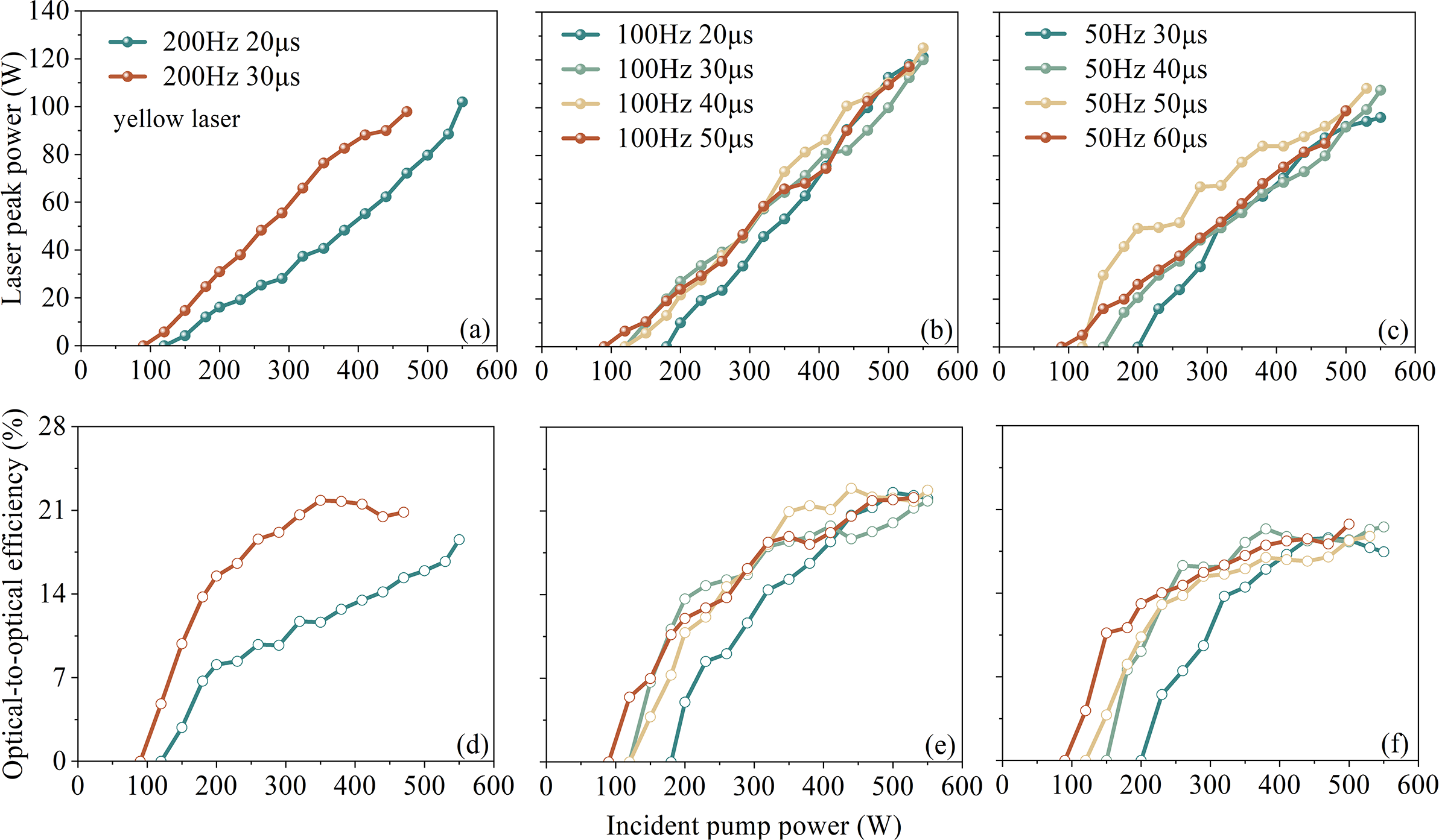
Figures 6(a) and 6(c) present representative spectra of the QCW yellow and orange lasers at various pump powers. For the yellow laser, the central wavelength shifted slightly from 565.0 to 565.8 nm as the incident pump power increased from 200 to 500 W. Similarly, for the orange laser, the central wavelength varied minimally from 590.3 to 590.8 nm over the same pump power range. These small wavelength shifts at high powers indicate that the multi-phonon-assisted laser maintains high spectral stability.
(a) QCW yellow laser spectra with different pump powers (100 Hz, 40 μs). (b) Evolutions of the temporal sequences of the pump light, fundamental-wave laser and visible laser pulses in QCW yellow lasers. (c) QCW orange laser spectra under different pump powers (100 Hz, 40 μs). (d) Evolutions of the temporal sequences of the pump light, fundamental-wave laser and visible laser pulses in QCW orange lasers.
The temporal characteristics of both QCW-pumped yellow and orange lasers were also examined. As shown in Figure 6(b), increasing the pump power from 200 to 500 W extended the pump pulse duration from 32 to 37 μs. Correspondingly, the pulse durations of the fundamental-wave (FW) yellow laser at 1130 nm increased from 27.4 to 33 μs, while those of the frequency-doubled yellow output at 565 nm grew from 24.5 to 32 μs. For the orange laser (Figure 6(d)), the FW output at 1180 nm exhibited pulse durations from 24.0 to 27.6 μs, and the frequency-doubled output at 590 nm extended from 20.0 to 25.0 μs.
In both lasers, the FW and visible outputs showed a monotonic increase in pulse duration with pump power, indicating a nonlinear dependence of pulse dynamics on pump intensity – likely influenced by thermal effects such as thermal lensing[ Reference Sun, Yang, Li, Zeng, Jiang and Feng 1 , Reference Yi, Dong, Li and Song 46 , Reference Cheng, Zhang, Huang, Deng, Huang, Li, Lin, Chen, Huang, Lin, Liao and Zhang 47 ]. At high pump powers, the pulse width of the yellow laser closely matched that of the pump light, whereas the orange laser maintained a more pronounced difference, suggesting a stronger thermal impact. These results highlight the importance of precisely controlling the pulse width and RF in high-power QCW-pumped systems to minimize pulse distortion.
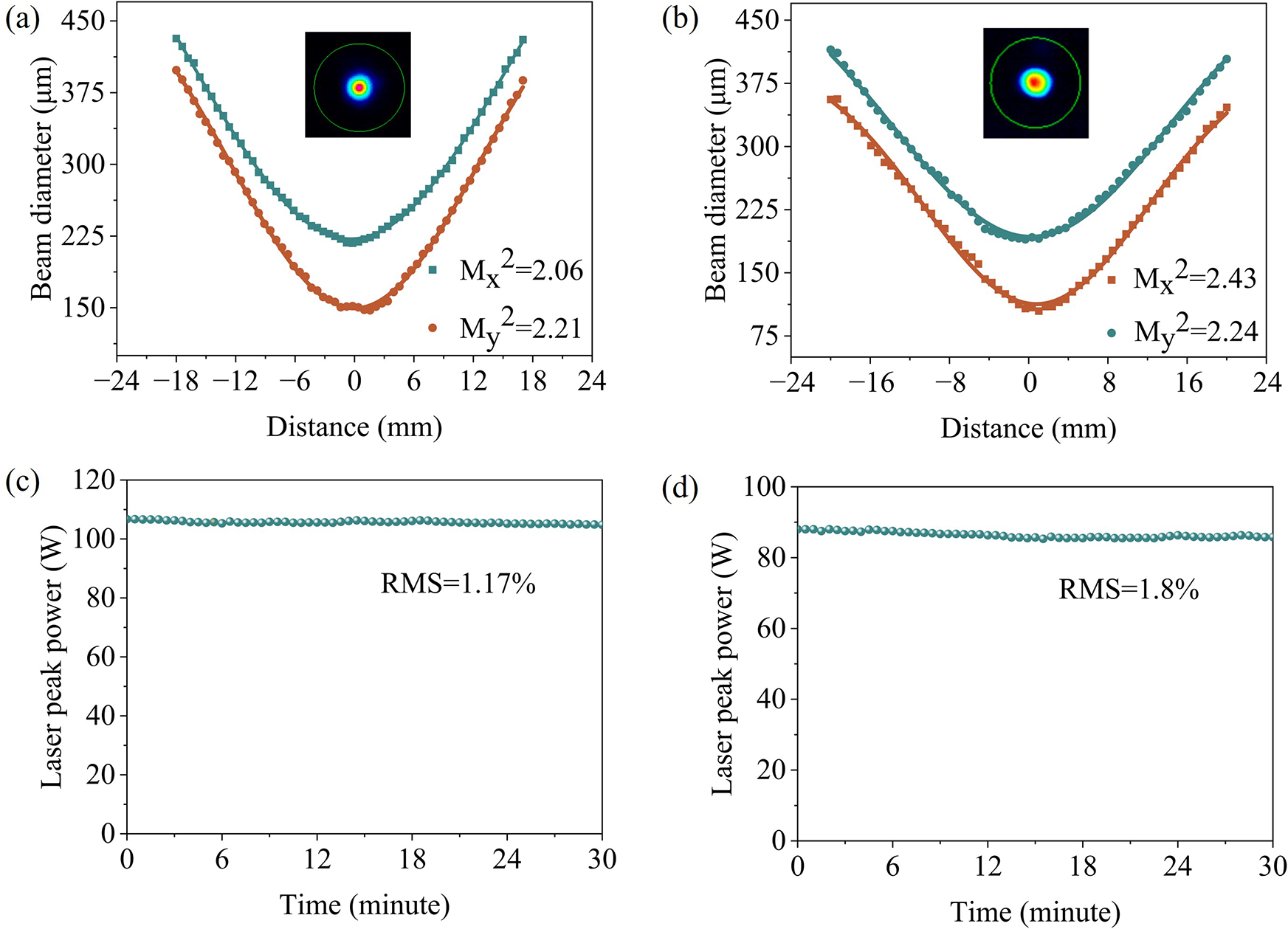
In addition, we measured the beam quality and power stability of the QCW-pumped yellow–orange laser. Figure 7(a) shows that the measured Mx 2 and My 2 values for the QCW yellow laser along the x- and y-directions were 2.06° and 2.21°, respectively, at an output peak power of 120 W. For the QCW orange laser, Figure 7(b) shows that the Mx 2 and My 2 values were 2.43° and 2.24°, respectively, at a peak power of 100 W. The insets show the two-dimensional beam profiles with spatial modes close to the Gaussian profiles. Compared to previous microchip self-frequency-doubling CW lasers (M 2 > 9)[ Reference Du, Chen, Yu and Zhang 33 ] and pulse lasers (M 2 > 4)[ Reference Du, Chen, Yu and Zhang 48 ], the M 2 factor of the QCW laser is significantly reduced, indicating that our QCW pumping strategy is very effective in promoting heat dissipation and reducing thermally induced beam distortion. To optimize laser beam quality, the implementation of dedicated thermal management techniques is essential. Utilizing thin-disk laser architectures, for instance, can effectively mitigate thermal accumulations and significantly improve beam qualities.
(a) Beam profile and beam quality of the QCW yellow laser. (b) Beam profile and beam quality of the QCW orange laser. (c) Power stability of the QCW yellow laser. The average value of peak power is 106.7 W. (d) Power stability of the QCW orange laser. The average value of peak power is 88 W.

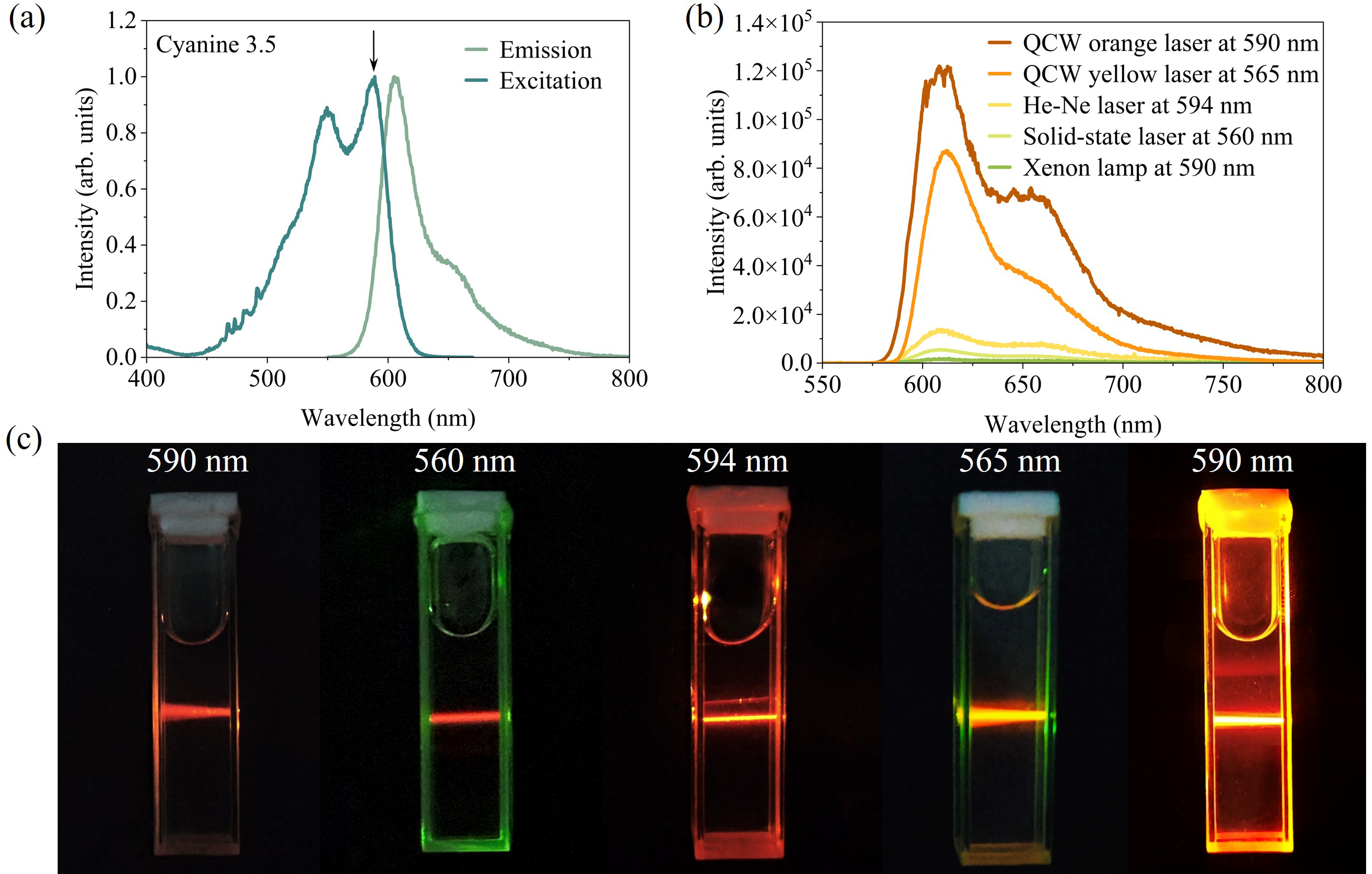
(a) Excitation and emission spectra of the Cyanine 3.5 (Alexa Fluor) dye, purchased from Duofluor, Inc. (Wuhan). (b) Fluorescence intensity obtained using different excitation sources. (c) Fluorescence images of Cyanine 3.5 under various excitations. The xenon lamp was operated in an Edinburgh FLS-1000 fluorescence spectrometer. The 594 nm He–Ne laser (LGK-7512-P) was sourced from Haike Sirui, Inc. (Beijing), and the 560 nm solid-state laser was purchased from Lasence, Inc. (Qingdao).

Power stability was assessed by monitoring output fluctuations over 30 min. Thermal effects are known to strongly influence the stability of self-frequency-doubling yellow–orange lasers[ Reference Wang, Yuan, Yu, Han, Du and Yu 49 ]. As shown in Figures 7(c) and 7(d), the root-mean-square (RMS) power fluctuations were 1.17% for the yellow laser and 1.8% for the orange laser – both lower than reported values for CW lasers (RMS = 2.14%[ Reference Du, Lu, Liang, Chen, Yu and Zhang 31 ] and 3.9%[ Reference Si, Liang, Zhou, Lu, Yu, Zhang and Wu 30 ], respectively). These improvements, attributable to reduced thermal loading, confirm the superior thermal management of the QCW pumping scheme and its ability to sustain high-power, stable yellow–orange laser output. In addition, polarization measurements showed that both lasers were linearly polarized, with polarization degrees of 99.4% (yellow laser) and 98.1% (orange laser).
Finally, we applied the stable QCW orange microchip laser in fluorescence experiments. Flow cytometry is a powerful technique for analysing multiple physical properties of single cells in suspension as they pass through an optical detection system[ Reference McKinnon 50 ]. Conventional flow cytometers typically use blue, green, red or deep-red laser sources, depending on the excitation requirements of the fluorescent dyes employed. Incorporating yellow and orange lasers can expand the range of excitable fluorophores[ Reference Kapoor, Karpov, Linton, Subach, Verkhusha and Telford 51 ], yet compact sources in these wavelength ranges remain scarce for flow cytometry applications.
We selected Cyanine 3.5 (Alexa Fluor) dye, a widely used fluorophore in flow cytometry, for the fluorescence experiments. As shown in Figure 8(a), the dye exhibits two excitation peaks at 550 and 590 nm, with a maximum emission peak at 606 nm. Five excitation sources were compared: a QCW orange laser (λ = 590 nm, P = 1 mW), a QCW yellow laser (λ = 565 nm, P = 1 mW), a He–Ne laser (λ = 594 nm, P = 1 mW), a solid-state laser (λ = 560 nm, P = 1 mW) and a xenon lamp (λ = 590 nm, P = 1 mW). As shown in Figure 8(b), the QCW orange laser produced fluorescence intensities 1.5, 9, 20 and 60 times higher than those from the QCW yellow laser, He–Ne laser, solid-state laser and xenon lamp, respectively. This enhancement significantly improves cellular detection sensitivity, particularly for samples with low cell concentrations. Visual fluorescence images in Figure 8(c) further confirm that the QCW orange laser yields the brightest emission, clearly visible to the naked eye. These findings underscore the potential of QCW multi-phonon-coupled lasers for advanced applications in flow cytometry, ophthalmic diagnostics and dermatological treatments[ Reference Greentree and Prawer 52 , Reference Anderson and Parrish 53 ].
4 Conclusion
This work presents the first investigation of QCW-pumped microchip yellow–orange lasers in self-frequency-doubling Yb:YCOB crystals. The QCW yellow laser achieved a maximum peak power of 125 W with a slope efficiency of 22.7%, while the QCW orange laser reached 102 W with a slope efficiency of 18.7%. To the best of our knowledge, these represent the highest reported values for QCW microchip yellow–orange lasers. Compared with Dy3+-doped crystals, the proposed multi-phonon-coupling mechanism offers superior spectral tunability and excellent power scaling capability. Thermal management and device miniaturization remain essential for advancing solid-state yellow–orange lasers towards portable medical and industrial applications. In the future, the use of high-concentration Yb:YCOB crystals (corresponding to high pump absorption) in combination with QCW pumping is expected to enable compact yellow–orange sources with ultrahigh output power and tunable wavelengths.
Acknowledgements
This study was supported by the National Key Research and Development Program of China (Grant Nos. 2023YFF0718801 and 2021YFB3601504), the National Natural Science Foundation of China (Grant Nos. 52025021, 52422201, 92463304 and 52372010), the Natural Science Foundation of Shandong Province (Grant Nos. ZR2023ZD53 and 2024ZLGX02) and the Future Plans of Young Scholars at Shandong University.


 Open access