


Introduction
Cloaking and invisibility are among the most popular research areas in electromagnetics, material science, optics, and related fields [Reference Shestopalov1]. Cloaking refers to concealing a particular object by controlling incident electromagnetic waves, thereby reducing the object’s total scattering cross-section (SCS) [Reference Salim and Maity2]. It is considered a method of radar cross-section reduction (RCS) [Reference Hamzavi-Zarghani, Yahaghi and Matekovits3]. Under ideal conditions, a cloaked object would suppress electromagnetic scattering across all angles, polarizations, and a wide frequency band; however, in practical applications, compromises are sometimes made on one or more of these conditions. A review of the literature reveals several cloaking techniques, each with its own advantages in performance and limitations in application. One such method, transformation optics (TO), has proven highly successful but presents a practical drawback due to the substantial thickness required relative to the size of the object being concealed [Reference Ma, Jiang, Yang, Zhou and Cui4]. Another technique, known as transmission-line cloaking, uses travelling modes to guide EM waves past cloaked regions, making multiple objects undetectable over a broad frequency band [Reference Alitalo and Tretyakov5]. Another method is the coordinate transformation cloaking technique [Reference Pendry, Schurig and Smith6–Reference Leonhardt8]. This method has been experimentally validated to be highly effective in frequency ranges such as radio frequency and near-infrared. This approach leverages the anisotropic and inhomogeneous profile of the cloak material to bend electromagnetic waves within the cloak, effectively rendering the object invisible. However, the cloaking techniques mentioned often rely on bulk metamaterials, which are not only challenging to produce but also considerably large relative to the object cloaked.
The other main technique is known as the scattering cancellation technique, which relies on wave cancellation involving the object to be hidden and an outer cloak. It aims to reduce the total SCSs of an object. This way, the fabrication challenges mentioned earlier, such as high variability and loss, will be overcome. One of the initial designs using this technique, the plasmonic cloak, was proposed in 2005 by Alu and Engheta [Reference Alù and Engheta9], while the mantle cloak design was introduced by Alu in 2009 [Reference Alù10]. Plasmonic cloak and mantle cloak designs involve similar mathematical analyses. However, while the plasmonic cloak design works with dielectric coatings, the mantle cloak design utilizes surfaces with specific layer properties. The term “mantle cloak” refers to a thin metasurface designed to achieve a specific surface impedance profile around the object. The mantle cloak technique utilizes metasurfaces to manipulate surface currents through engineered surface impedance. In a study [Reference Edwards, Alù, Silveirinha and Engheta11], effective cloaking was achieved by designing a plasmonic cloak that consists of a configuration of metallic fins integrated into a high-permeability fluid. Another technique for invisibility is the use of inhomogeneous or anisotropic surface cloaks in designs [Reference Younesiraad, Hamzavi-Zarghani and Matekovits12] and [Reference Tay and Chen13]. This method is based on the ability to independently control the wave transmission and reflection. That is, invisibility is achieved by manipulating the phase, amplitude, and polarization of EM waves. This scattering cancellation technique has increased the interest in cloaking in the EM engineering community due to its easier design and practical application. Research on mantle cloak designs, encompasses anisotropic metasurface cloaks [Reference Monti, Soric, Alù, Toscano and Bilotti14], tunable metasurface cloaks [Reference Hamzavi-Zarghani, Yahaghi, Matekovits and Farmani15], dual-polarized cloaking [Reference Shcherbinin, Moskvitina, Fesenko and Tuz16], wideband metasurface cloaks [Reference Moreno, AB, HM, Dh, Xin, Monti, Bilotti and Alu17], dual-band mantle cloaks [Reference Tay, Chen and Hee18, Reference Bodur and Çimen19], and antenna applications of mantle cloak [Reference Masoumi, Kazemi and Fathy20–Reference Hamzavi-Zarghani, Monti, Vellucci, Longhi, Barbuto, Ramaccia, Stefanini, Toscano and Bilotti23]. Also in [Reference Soric, Monti, Toscano, Bilotti and Alù24], dual-band capabilities are achieved through the use of a multilayer cloaking structure. However, the disadvantage of this design is its layered form. In addition to these designs, metasurface-based cloak designs also have recently attracted significant attention due to their thinness, ease of being patched or coated onto the object to be hidden, design flexibility, and functionality for various applications [Reference Soric, Chen, Kerkhoff, Rainwater, Melin and Alù25–Reference Forouzmand and Yakovlev27].
However, there is still a need to design effective scattering cancellation cloaks with different geometries and capabilities. In recent years, numerous studies have explored mantle cloaking using various unit cell geometries [Reference Younesiraad, Hamzavi-Zarghani and Matekovits12–Reference Monti, Soric, Alù, Toscano and Bilotti14, Reference Tay, Chen and Hee18, Reference Bodur and Çimen19, Reference Soric, Chen, Kerkhoff, Rainwater, Melin and Alù25, Reference Padooru, Yakovlev, Chen and Alù26, Reference Liu, Zhang, Xu and Cui28–Reference Liu, Xu, Zhang and Cui33]. While many of these works emphasize conceptual novelty or involve complex fabrication techniques, this study introduces a novel, thin, and single-layer unit cell design that achieves notable improvement in RCS reduction. Importantly, the proposed cloak is analyzed not only for normal incidence but also for oblique wave arrivals, demonstrating effective RCS reduction across all these scenarios. The results are further supported by electric field distribution analyses and practical implementation. In this work, the target object is electrically small, with a dimension-to-wavelength ratio that satisfies the quasi-static condition often assumed in mantle cloaking studies, thereby allowing the use of flat metasurface unit cells for design optimization. Our approach combines a simple, planar unit cell topology with a conformal arrangement on the cylindrical surface, providing a practical and efficient cloaking solution. This balance between high performance, structural simplicity, and minimal thickness distinguishes our work from prior contributions and demonstrates its potential for real-world electromagnetic cloaking applications. The novelty of this paper is that by using a new geometry, different from a conventional patch geometry, a scattering cancellation at the design frequency is achieved that is considerably higher than what has been reported in the literature. When the literature is reviewed, it is found that there are very few mantle cloak studies based on a new unit cell design. This study also demonstrates superior RCS reduction compared to mantle cloak designs that do not use traditional unit cells found in the literature [Reference Tay and Chen13, Reference Tay, Chen and Hee18, Reference Liu, Zhang, Xu and Cui28]. Physical size is an important constraint for electromagnetic cloaks; although an original unit cell design was used, the reference [Reference Younesiraad, Hamzavi-Zarghani and Matekovits12] design was completed as a multi-layer structure around a conductive cylinder. In this study, a mantle cloak with a novel unit cell design is proposed for the scattering suppression of cylindrical metasurface. The surface impedance of the designed unit cell, determined through S-parameter analysis, was adjusted to match the surface impedance obtained from the analytical formula to reduce electromagnetic scattering. To investigate the mantle cloak performance of this proposed unit cell, the bi-static radar cross section is obtained. Bi-static RCS analyses have been conducted for the cloaked and uncloaked cases of cylinders for normal and oblique incidence. Significant reduction in scattering is attained at the operational frequency across all directions. Finally, the design of the mantle cloak has been presented and verified through experimentation.
Theory
The problem under investigation involves the scattering of a transverse magnetic ( $T{M_z}$)-polarized plane wave by a perfect electric conductor (PEC) cylinder coated with a thin mantle cloak. The cylinder is assumed to have a finite length (L = 19.4 cm) and is immersed in free space. The analysis is carried out under the time harmonic assumption, where all field quantities vary as
  ${e^{j\omega t}}$. Accordingly, Maxwell’s equations and the boundary conditions are formulated for the TM case with the electric field oriented along the z-axis. Figure 1 illustrates the configuration and main parameters of the problem. This section examines the surface impedance formula for designing a thin single-layer metasurface cloaking around a conductive cylinder. To determine the geometric dimensions of the unit cell elements on the cylindrical surface, it is necessary to calculate the surface impedance
  ${Z_s}$ that enables effective scattering reduction at the specified frequency. The cloaking model depicted in Fig. 1(a) consists of a PEC cylinder with a radius of
  $a$, enveloped by a thin dielectric spacer and metasurface layer, resulting in a total radius of
  $b$.
$b$.
(a) Cross-sectional and (b) comprehensive view of structure.

The geometric characteristics of the unit cell can be described by a homogeneously uniform surface impedance ( ${Z_s}$) when exposed to a plane wave with TM polarization incident at normal angle.
  ${Z_s}$ is an important parameter in mantle cloak designs. The electromagnetic scattering can be minimized with appropriate
  ${Z_s}$. It is given that the equation for surface impedance is
  ${Z_s} = {R_s} - j{X_s}$. Here
  ${R_s}\,$denotes the surface resistance, which accounts for the ohmic losses, and
  ${X_s}\,$represents the surface reactance, which is associated with − but not identical to − the stored electromagnetic energy in the near field. Both
  ${R_s}\,$and
  ${X_s}\,$are expressed in ohms (Ω). The surface impedance
  ${Z_s}$ is linked to the mean tangential electric field (
 ${{\mathbf{E}}_{{\text{tan}}}}$) and the mean electric surface current density
  ${\mathbf{J}}$, expressed as
  ${{\mathbf{E}}_{{\text{tan}}}} = {Z_s}.{ }{\mathbf{J}}$. Here,
  ${\mathbf{J}} = \hat n{ } \times { }({\mathbf{H}}_{{\text{tan}}}^ + - { }{\mathbf{H}}_{{\text{tan}}}^ - $) which
  ${\mathbf{H}}_{{\text{tan}}}^ + $ and
  ${\mathbf{H}}_{{\text{tan}}}^ - $ denote the tangential components of the magnetic field at the external and internal interfaces of the cylindrical metasurface. For a lossless surface, the surface impedance is purely imaginary and can be expressed as
  ${Z_s} = - j{X_s}$. The scattering problem at the interface
  $\rho = b$ of the mantle cloak is solved using Mie scattering theory, considering impedance boundaries on both the inner and outer surfaces of the structure. Thus, at
  $\rho = b$, the relationship between the tangential electric field
  ${{\mathbf{E}}_{{\text{tan}}}}$ and tangential magnetic field
  ${{\mathbf{H}}_{{\text{tan}}}}$ is governed by the surface impedance, as depicted in equation (1a) [Reference Padooru, Yakovlev, Chen and Alù29]. The boundary conditions for ρ = a are given in equation (1b).
 \begin{equation}{\left. {{{\mathbf{E}}_{{\text{tan}}}}} \right|_{{{\rho }} = {{\text{b}}^ + }}} = {\left. {{{\mathbf{E}}_{{\text{tan}}}}} \right|_{{{\rho }} = {{\text{b}}^ - }}} = {Z_s}\left( {{{\left. {{{\mathbf{H}}_{{\text{tan}}}}} \right|}_{{{\rho }} = {{\text{b}}^ + }}} - {{\left. {{{\mathbf{H}}_{{\text{tan}}}}} \right|}_{{{\rho }} = {{\text{b}}^ - }}}} \right)\end{equation}
 \begin{equation}{\left. {{{\mathbf{E}}_{{\text{tan}}}}} \right|_{{{\rho }} = {{\text{a}}^ - }}} = 0\end{equation}
In this section, the analytical formulation based on Mie theory is summarized to determine the required surface impedance for scattering suppression. Although the study mainly focuses on experimental verification, a complete theoretical framework is provided below for clarity.
The total electric field in the TM case (with  ${E_z}$ polarization) can be expanded in cylindrical harmonics according to Mie theory as:
 \begin{equation}{E_z}\left( {{{\rho }},{{\varphi }}} \right) = \left\{\!{\begin{array}{*{20}{c}}
{\mathop \sum \limits_{n = - \infty }^\infty {A_n}{J_n}\left( {{k_d}{{\rho }}} \right){e^{jn{{\varphi }}}},\,\,\,\,\,\,\,\,\,\,\,\,\,\,\,\,\,\,\,\,\,\,\,\,\,\,\,\,a \lt \rho \lt b,}\\ \\
{\mathop \sum \limits_{n = - \infty }^\infty \left[ {{J_n}\left( {{k_0}{{\rho }}} \right) + C_n^{TM}H_n^{\left( 2 \right)}\left( {{k_0}{{\rho }}} \right)} \right]{e^{jn{{\varphi }}}},\,\,\,\,\,\,\,\rho \gt b,}
\end{array}} \right.\end{equation}
\begin{equation}{E_z}\left( {{{\rho }},{{\varphi }}} \right) = \left\{\!{\begin{array}{*{20}{c}}
{\mathop \sum \limits_{n = - \infty }^\infty {A_n}{J_n}\left( {{k_d}{{\rho }}} \right){e^{jn{{\varphi }}}},\,\,\,\,\,\,\,\,\,\,\,\,\,\,\,\,\,\,\,\,\,\,\,\,\,\,\,\,a \lt \rho \lt b,}\\ \\
{\mathop \sum \limits_{n = - \infty }^\infty \left[ {{J_n}\left( {{k_0}{{\rho }}} \right) + C_n^{TM}H_n^{\left( 2 \right)}\left( {{k_0}{{\rho }}} \right)} \right]{e^{jn{{\varphi }}}},\,\,\,\,\,\,\,\rho \gt b,}
\end{array}} \right.\end{equation}where  ${J_{}}\left( . \right)$ and
  $H_n^{\left( 2 \right)}\left( . \right)\,$denote the Bessel and Hankel functions of the second kind, respectively, and
  ${A_n}\,$and
  $C_n^{TM}\,$are coefficients of the internal and scattered fields, determined from the boundary conditions given in equations (1a) and (1b). Here,
  $H_n^{\left( 2 \right)} = {J_n} - j{Y_n}\,$represents outward propagating cylindrical waves.
The total scattering width (SW) corresponds to the total scattered power per unit length of the cylinder normalized to the incident power density and is formally defined as:
 \begin{align}SW = \mathop \int \limits_{0}^{2\pi} \frac{{{\left| {{E_s}\left( {{\varphi }} \right)} \right|}^2}}{{{{\left| {{E_i}} \right|}^2}}}d{{\varphi }}\end{align}
where  ${E_s}\left( {{\varphi }} \right)\,$and
  ${E_i}$ denote the scattered and incident electric field amplitudes, respectively.
For two-dimensional scattering, this expression represents the total scattered power integrated over all observation angles. The analytical expression used in this study is then obtained as given in equation (4).
The total SW, which serves as a measure of the cylinder’s detectability, is defined by equation (4) [Reference Padooru, Yakovlev, Chen and Alù29].
 \begin{equation}\sigma = SW = \frac{4}{{{k_0}}}\mathop \sum \limits_{n = - \infty }^\infty {\left| {{C_n}^{TM}} \right|^2}\end{equation}
where  ${k_0} = 2\pi /{\lambda _0}\,$is the free space wave number.
The  ${n_{th}}$ cylindrical scattering harmonic
  ${C_n}^{TM}$ is given by
  ${C_n}^{TM} = - \frac{{{P_n}^{TM}}}{{{P_n}^{TM} + j{Q_n}^{TM}}}$, where
  ${P_n}^{TM}$ and
  ${Q_n}^{TM}$ are defined in equations (5) and (6) [Reference Luo, WL, Ding, Du, Chen, Zhao, Jiang and Feng30]:
 \begin{equation*}
{P_n}^{TM} = \left|\begin{array}{@{}l@{\quad}l}
{J_n}\left( {{k_d}a} \right) & {Y_n}\left( {{k_d}a} \right) \\
{J_n}\left( {{k_d}b} \right)& {Y_n}\left( {{k_d}b} \right) \\
{J_n}\left( {{k_d}b} \right)
- \,j\frac{1}{{{\eta _d}}}{Z_s}\,{J_n}'\left( {{k_d}b} \right)& {Y_n}\left( {{k_d}b} \right) -\, j\frac{1}{{{\eta _d}}}{Z_s}\,{Y_n}'\left( {{k_d}b} \right) \end{array}\right.\end{equation*}
\begin{equation*}
{P_n}^{TM} = \left|\begin{array}{@{}l@{\quad}l}
{J_n}\left( {{k_d}a} \right) & {Y_n}\left( {{k_d}a} \right) \\
{J_n}\left( {{k_d}b} \right)& {Y_n}\left( {{k_d}b} \right) \\
{J_n}\left( {{k_d}b} \right)
- \,j\frac{1}{{{\eta _d}}}{Z_s}\,{J_n}'\left( {{k_d}b} \right)& {Y_n}\left( {{k_d}b} \right) -\, j\frac{1}{{{\eta _d}}}{Z_s}\,{Y_n}'\left( {{k_d}b} \right) \end{array}\right.\end{equation*} \begin{align}
\left.\begin{array}{lc} & 0 \\
& {J_n}\left( {{k_0}b} \right) \\
&{ - j\frac{1}{{{\eta _0}}}{Z_s}\,{J_n}'\left( {{k_0}b} \right)} \end{array} \right|\end{align}
\begin{align}
\left.\begin{array}{lc} & 0 \\
& {J_n}\left( {{k_0}b} \right) \\
&{ - j\frac{1}{{{\eta _0}}}{Z_s}\,{J_n}'\left( {{k_0}b} \right)} \end{array} \right|\end{align} \begin{equation*}
{Q_n}^{TM} = \left|\begin{array}{@{}l@{\quad}l}
{J_n}\left( {{k_d}a} \right)& {Y_n}\left( {{k_d}a} \right) \\
{J_n}\left( {{k_d}b} \right)& {Y_n}\left( {{k_d}b} \right) \\
{J_n}\left( {{k_d}b} \right) - j\frac{1}{{{\eta_d}}}{Z_s}\,{J_n}'\left( {{k_d}b} \right)& {Y_n}\left( {{k_d}b} \right) - j\frac{1}{{{\eta _d}}}{Z_s}\,{Y_n}'\left( {{k_d}b} \right) \end{array}\right.\end{equation*}
\begin{equation*}
{Q_n}^{TM} = \left|\begin{array}{@{}l@{\quad}l}
{J_n}\left( {{k_d}a} \right)& {Y_n}\left( {{k_d}a} \right) \\
{J_n}\left( {{k_d}b} \right)& {Y_n}\left( {{k_d}b} \right) \\
{J_n}\left( {{k_d}b} \right) - j\frac{1}{{{\eta_d}}}{Z_s}\,{J_n}'\left( {{k_d}b} \right)& {Y_n}\left( {{k_d}b} \right) - j\frac{1}{{{\eta _d}}}{Z_s}\,{Y_n}'\left( {{k_d}b} \right) \end{array}\right.\end{equation*} \begin{align}
\left.\begin{array}{lc} &0 \\
& {J_n}\left( {{k_0}b} \right) \\
& { - j\frac{1}{{{\eta _0}}}{Z_s}\,{Y_n}'\left( {{k_0}b} \right)}
\end{array} \right|\end{align}
\begin{align}
\left.\begin{array}{lc} &0 \\
& {J_n}\left( {{k_0}b} \right) \\
& { - j\frac{1}{{{\eta _0}}}{Z_s}\,{Y_n}'\left( {{k_0}b} \right)}
\end{array} \right|\end{align} Here,  ${J_n}\left( {\text{.}}\right)\,$and
  ${Y_n}\left( {\text{.}} \right)\,$denote the Bessel and Neumann functions of the first and second kinds, respectively.
The condition  ${P_n}^{TM} = 0$ must be met for ideal cloaking performance, which requires complete elimination of any scattering from the object, leading to no scattering and complete invisibility. The required surface impedance (
 ${Z_s}$) to achieve scattering reduction will then be obtained as shown in equation (7) [Reference Younesiraad, Bemani and Nikmehr34].
 \begin{equation}{Z_s} = - \frac{j}{{\frac{1}{{{\eta _d}}}\frac{{{ }{J_n}\left( {{k_d}a} \right){ }{Y_n}^{\text{'}}\left( {{k_d}b} \right) - { }{J_n}^{\text{'}}\left( {{k_d}b} \right){ }{Y_n}\left( {{k_d}a} \right)}}{{{ }{J_n}\left( {{k_d}a} \right){ }{Y_n}\left( {{k_d}b} \right) - { }{J_n}\left( {{k_d}b} \right){ }{Y_n}\left( {{k_d}a} \right)}} - \frac{1}{{{\eta _0}}}\frac{{{ }{J_n}^{\text{'}}\left( {{k_0}b} \right)}}{{{ }{J_n}\left( {{k_0}b} \right)}}}}\end{equation}
 It should be clarified that equation (7) provides the value of the surface impedance  ${Z_s}\,$that fulfills the condition
  $P_n^{TM} = 0\,$ for a specific harmonic order
  $n$, typically for the dominant mode (
 $n = 0$). In practice, it is not possible to make
  $P_n^{TM} = 0\,$ for all n simultaneously using a single isotropic surface impedance. Therefore, the analytical
  ${Z_s}$ value derived from equation (7) corresponds to the optimal impedance that minimizes the total SW by suppressing the dominant scattering mode.
The functions  ${J_n}\left( . \right)$ and
  ${Y_n}\left( . \right)$ correspond to the
  $n$-th order Bessel and Neumann functions, in that order. Here,
  ${{{\eta }}_d}$ and
  ${{\text{k}}_d}$ denote the wave impedance and wave number of the dielectric spacer located between the PEC cylinder and the mantle cloak surface, whereas ɳ₀ and k₀ represent the corresponding parameters in free space. By appropriately selecting the values of the dielectric constant
  ${\varepsilon _r}$, total radius
  $b$, and surface reactance
  ${X_s}$ around the cylinder,
  ${P_n}^{TM}$ can be made zero, thereby reducing the overall scattering of the object. In this design, a novel unit cell is utilized as the metasurface unit element. A thin single-layer electromagnetic cloak metasurface is designed for a frequency of
  $f = 3$ GHz by wrapping a dielectric spacer with a thickness of
  $h = 1.27{ }$ mm, a dielectric constant of
  ${\varepsilon _r} = 10.2$ (Rogers 3010) and the electrical loss tangent
  $tan{{\delta }} = 0.0022\,$ around a conducting cylinder with a radius of
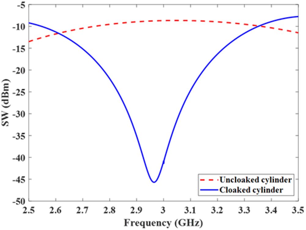
  $a = 12.5$ mm. Figure 2 shows the graph of the total SW as a function of frequency. The SW graph is generated using the formula in (4) to assess the effectiveness of the cloaking. In order to enhance the reduction of scattered fields, the total SW should be decreased by attenuating the dominant mode’s scattering coefficient. The term
  ${C_n}^{TM}$, with
  $n = 0$ being the dominant term, represents the scattering harmonic for electrically small cylinders with a radius less than
  $0.1{\lambda _0}$, where
  ${\lambda _0}$ denotes the free space wavelength corresponding to the operating frequency. In this situation, the overall radius of the cylinder (
 $b$) is linked to the radius of the PEC cylinder (a) by
  $b = 1.1a$, with the total radius specified as
  $b = 0.13{\lambda _0}$. In these conditions, the primary contributors to the overall scattering from the cylinder are the first five (
 $n = 0, \pm 1, \pm 2$). Lower-order harmonics, specifically up to the fifth, are the principal contributors to the electromagnetic scattering from the cylinder [Reference Shestopalov1]. Using equation (7), the surface impedance required to reduce scattering for
  $n = 0$ is calculated to be
  ${Z_s} = - j32,298$ ohms. In [Reference Chen and Alù31], after analyzing the SW analytical results for an ideal mantle cloak and a conducting cylinder, it was observed that scattering can be significantly reduced if the surface impedance exhibits a capacitive effect. It can be seen that this calculated surface impedance meets the previously mentioned condition, namely that the surface impedance is capacitive. In Fig. 2, the minimum SW for the cloaked cylinder occurs slightly below the design frequency of 3 GHz. This small shift is mainly due to the contribution of higher-order cylindrical harmonics
  $\left( {n = \pm 1, \pm 2} \right)$ that are not completely suppressed in the full-wave simulation, as well as minor variations in the effective surface reactance
  ${X_s}$ caused by metasurface dispersion and curvature effects.
 $S$W of both uncloaked and cloaked conducting cylinder with dimensions of
  $a = 12.5$ mm,
  ${{{\varepsilon }}_r} = 10.2$ and
  $h = 1.27$ mm.

Design of single-layer metasurface cloak
In “Theory” section, it was established that the cloak structure must have a capacitive surface impedance to achieve scattering reduction. Therefore, in this section, the metasurface unit cell with a high capacitive response and a novel geometry is proposed. The unit cell surface design is novel and differs from the conventional unit cells typically used in mantle cloak designs found in the literature. The proposed structure has a thin single-layer novel unit cell cloaked cylinder is made of  $0.13{\lambda _0}\,$ total radius and
  $0.0127{\lambda _0}$ dielectric spacer’s thickness at the design frequency
  ${f_0} = {3}$ GHz. The unit cell parameters are determined based on the surface impedance. The impedance obtained from S-parameter analysis of the designed unit cell is adjusted to align with the impedance calculated using the analytical formula to minimize electromagnetic scattering, thereby finalizing the dimensions. Full-wave analysis of the unit cell was performed at CST Microwave Studio. The
  ${Z_s}$ value of a unit cell can be obtained from the transmission
  $({S_{21}})$ and reflection coefficients
  $({S_{11}})$ using equation (8) [Reference Tay, Chen and Hee18].
 \begin{equation}{Z_s} = \frac{{{\eta _0}\left( {1 + {S_{11}} + {S_{21}}} \right)}}{{2\left( {1 - {S_{11}} - {S_{21}}} \right)}}\end{equation}
where  ${\eta _0} = \sqrt {\mu /\varepsilon } $ is the wave impedance in free space.
  $\mu \,$and
  $\varepsilon \,$ are the permeability and permittivity of the medium, respectively.
The boundary conditions for the unit cell are set for the simulation, and the ports are configured to interact with interfaces using z-polarized plane waves. In this configuration, the whole system is treated as an integrated metasurface, with the combined transmission and reflection providing the equivalent  ${Z_s}$. As illustrated in Fig. 3, the surface impedance of the proposed novel unit cell is determined to be
 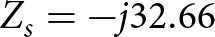 ${Z_s} = - j32.66$ ohms at the design frequency of
  $f = 3{ }$ GHz. In “Theory” section, the surface impedance needed to reduce scattering was calculated using the analytical formula, yielding
 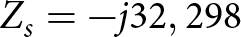 ${Z_s} = - j32,298$ ohms. The impedance value obtained from the S-parameter is very close to this value.
The surface impedance of the proposed unit cell according to frequency.

The unit cell geometry used in the surface design is shown in Fig. 4(a). This unit cell geometry differs from the conventional designs found in the literature. The selected geometry was intentionally configured to yield a capacitive surface impedance, satisfying the condition  ${X_s}$ < 0 required for suppressing the dominant TM0 scattering mode. The asymmetric narrow gaps increase the electric-field concentration between adjacent metallic regions, enhancing the effective capacitance. This capacitive reactance generates an out-of-phase surface current relative to the incident magnetic field, thereby cancelling the forward-scattered field. The design achieves the analytical impedance value purely through geometrical tuning. The dimensions of the parameters used in the design are provided in Table 1.
(a) Layout of the proposed unit cell; (b) periodic settlement of unit cells.

The geometrical measurements of the proposed unit cell

The value of  $D$, which represents the unit cell size shown in Fig. 4(b), is obtained using equation (9). In this equation,
  $N$ represents the number of unit cells around the cylinder, while
  $b$ denotes the total radius of the cylinder. As shown in the equation, the unit cell size is directly related to the number
  $N$ and the cylinder radius. In our previous study [Reference Bodur and Çimen19], we examined the effects of
  $N$ on mantle cloak performance. For this study,
  $N$ was chosen to be 8.
 \begin{equation}D = \frac{{2\pi b}}{N}\end{equation}
 After determining the values of  $D$ and
  $N$, the remaining geometric characteristics of the proposed unit cell are established to meet the previously obtained surface impedance. For this purpose, the S-parameter of the unit cell is analyzed. The surface impedance of the designed unit cell, as calculated from S-parameter analyses, is adjusted to match the surface impedance obtained from the analytical formula. This adjustment helps reduce electromagnetic scattering and determines the lengths needed for the design. In this design, the electromagnetic cloak is engineered for a design frequency of
  $f = 3{ }$ GHz using a thin, single-layer metasurface with novel unit cell structure. This structure consists of a thin metasurface design wrapped around a conductive cylinder with a
  $a = 12.5$ mm radius and a dielectric spacer in between with a thickness of
  $h = 1.27$ mm and a dielectric constant of
  ${\varepsilon _r} = 10.2$ (Rogers 3010 lossy). After determining the geometric dimensions of the unit cell, the mantle cloak is realized by wrapping the cylinder with a periodic array of these cells, as illustrated in Fig. 1(b), thereby completing the design. Although the dimensions are calculated for the flat geometry, this approach utilizes them to construct conformal cylindrical mantle cloaks. The unit cell dimensions were initially optimized assuming a locally flat geometry, a common and validated approach in metasurface design. Once optimized, these cells were conformally arranged along the cylindrical surface to construct the mantle cloak. Given that the unit cell dimensions remain within the subwavelength scale relative to the operating wavelength, and that the structure operates in the quasi-static regime (
 $ka \approx 0.785$), the local flat surface approximation remains valid. This is further supported by full-wave simulation results, which not only confirm the expected scattering reduction performance but also demonstrate that the curvature of the cylindrical surface does not significantly influence the effective surface impedance. These findings reinforce the applicability of the locally flat approximation for the designed mantle cloak. The finite length (
 $L$) of the cylinder in the z-axis direction is specified as
  $L = 19.4{ }$ cm for both the cloaked and uncloaked configurations.
Results and discussion
To investigate the cloaking properties of the cylindrical structure formed by the proposed unit cell, full-wave analyses were performed using a time-domain solver in CST Microwave Studio. Figure 5 shows TM-polarized plane waves at normal incidence illuminating both the cloaked and uncloaked cylinders. The plane wave traveling in the x-direction, with its electric field oriented parallel to the z-axis.
Exposure of (a) cloaked and (b) uncloaked cylinders to a TM-polarized incident plane wave.

To validate the numerical simulations, the analytical results derived from Mie theory were compared with the CST full-wave simulations. The total SCS was obtained by integrating the differential scattering cross section over the entire solid angle using the far-field electric field data exported from CST Microwave Studio. It is obtained by integrating the differential scattering cross section over all solid angles as:
 \begin{equation}{\sigma _{sca}} = SCS = \mathop \int \limits_{0}^{2\pi} \mathop \int \limits_{0}^{\pi} \frac{{{r^2}\left( {{\left| {{E_\theta }\left( {\theta ,\varphi } \right)} \right|}^2} + {{\left| {{E_\varphi }\left( {\theta ,\varphi } \right)} \right|}^2} \right)}}{{{\left| {{E_{inc}}} \right|}^2}}d{{\Omega}}\end{equation}
where  ${\sigma _{sca}}$(m2); total scattering cross section,
  ${E_\theta }\left( {\theta ,\varphi } \right)$,
  ${E_\varphi }\left( {\theta ,\varphi } \right)\left( {\frac{{\text{V}}}{{\text{m}}}} \right);$ is scattered electric field components in
  $\theta $ and
  $\varphi $ directions obtained from CST far-field data,
  ${E_{inc}}\,$ is the incident field amplitude (V/m) normalized to 1 V/m in this study, r is the distance to the observation point (m), and
  $d{{\Omega }} = sin\theta d\theta d\varphi $ is the solid angle element.
This formulation ensures that the scattering contributions from all directions are included in the total SCS, not only from a single cut-plane. The integration is performed numerically over the discrete  $\theta $ and
  $\varphi $ samples available from the CST far-field export.
Additionally, for cylindrical scatterers of length L, the SW is calculated by normalizing the SCS with respect to the object length:
 \begin{equation}SW = \frac{{{\sigma _{sca}}}}{L}\,\left( m \right)\end{equation}
Both SCS and SW values were converted into logarithmic scale (dBsm and dBm, respectively) for a consistent comparison with analytical Mie theory predictions. This enables direct comparison between the 3D CST simulation results and the 2D analytical Mie model.
Figure 6 shows a small frequency offset between the analytical (Mie theory) and CST-derived SCS and SW curves. To further validate the analytical model, the simulation setup was updated to simulate an infinitely long cylinder by applying periodic boundary conditions (PBCs) along the z-axis. The results indicate that the resonance frequency remains centered at approximately 3.1 GHz, confirming that the observed shift is not primarily associated with axial truncation effects. Instead, the slight frequency deviation (≈3%) is attributed to the dispersive nature of the metasurface unit cell and the subtle mutual coupling effects occurring on the curved surface, which are not fully captured by the simplified constant-impedance analytical model. Despite this small offset, the analytical and numerical results exhibit consistent resonance behavior and scattering suppression trends, thereby validating the proposed analytical formulation. It is worth noting that additional bi-static RCS results obtained under the same PBC based configuration are presented in Fig. 7, providing further confirmation of the analytical validation.
Validation of analytical and full-wave simulation results: (a) SCS versus frequency for cloaked and uncloaked cylinders, obtained from Mie theory and CST simulations for finite and infinite (PBC) cylindrical models; (b) corresponding SW comparison.

Bi-static radar cross section of cloaked and uncloaked cylinders for finite length and infinite length (PBC) simulation models.

Following the validation of the analytical model through the comparison of the SCS and SW results, the scattering performance is further analyzed in terms of the RCS. While the SW represents the total scattering integrated over all observation angles, the RCS describes the angular distribution of the scattered field in specific directions. Therefore, a reduction in RCS over the main scattering angles directly corresponds to a reduction in the total scattered power and confirms the effectiveness of the cloak. The use of RCS in this section also facilitates direct comparison with experimental measurements, which are typically performed in monostatic or bi-static RCS configurations. As the plane wave arrives at angles  $\theta = {90^\circ }$ and
  $\varphi $ =
  ${0^\circ }$, the RCS versus frequency characteristics of both the cloaked and uncloaked cylinders are analyzed in the plane defined by
  $\theta = {90^\circ }$ and
  $\varphi $ =
  ${180^\circ }$, considering both the finite length model and the z-axis PBC configuration that simulates an infinitely long cylinder. From Fig. 7, it is observed that the finite length cloaked cylinder exhibits a maximum RCS reduction of approximately
 $\,16.65$ dB at around
  $f = 3.1{\text{ GHz}}$, whereas the PBC based configuration yields the maximum RCS suppression at approximately
  $f = 3.05{\text{ GHz}},$ which is closer to the analytical design frequency of 3 GHz. This minor frequency shift is attributed to the same physical mechanisms discussed for Fig. 2, namely the contribution of higher-order cylindrical harmonics that are not completely suppressed in the full-wave simulation, along with minor variations in the effective surface reactance caused by metasurface dispersion and dielectric/conductor losses. These effects slightly alter the resonance condition of the metasurface but do not change the overall scattering-suppression behavior of the cloak.
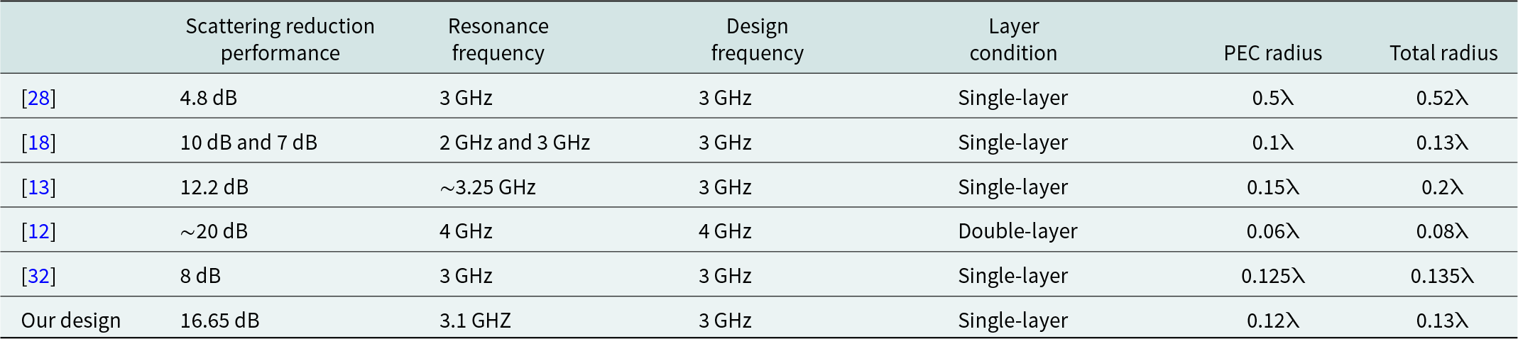
The objective of this work is to develop a single-layer mantle cloak utilizing a novel unit cell structure. It is well-established that reducing scattering along the full circumference of the cylinder is necessary to realize efficient mantle cloaking. Table 2 provides a comparison of mantle cloaks with innovative unit cells from the literature, alongside the scattering reduction performance of the proposed design in this study. In terms of scattering reduction, the proposed design significantly outperforms other studies. Even though a scattering reduction of 20 dB has been achieved in [Reference Younesiraad, Hamzavi-Zarghani and Matekovits12], the design in that study uses a double-layer structure. In contrast, the single-layer approach presented here simplifies fabrication processes. Moreover, the ultra-thin and single-layer configuration of the proposed mantle cloak contributes positively to its overall mass. As a result, a detailed comparison table has been included to position the proposed design within the context of existing mantle cloak studies that employ novel unit cell geometries. Unlike many previous works, which often prioritize conceptual novelty or rely on complex fabrication schemes, our approach demonstrates a significant improvement in RCS reduction while maintaining a simple and planar unit cell topology. The presented design achieves a lower RCS compared to previous studies, while also using a conformal arrangement that facilitates practical implementation. This balance between high cloaking performance and structural simplicity sets our work apart from earlier contributions. Thus, rather than merely replicating prior designs, our study advances the state-of-the-art by offering a more efficient and practically realizable solution for electromagnetic cloaking applications. The presented design demonstrates notable scattering reduction when compared to similar designs detailed in Table 2. The resonance frequency reported in Table 2 corresponds to the frequency at which the designed cloak exhibits maximum RCS reduction (3.1 GHz in this study), which is very close to the intended design frequency of 3 GHz. This slight deviation reflects the resonant behavior of the capacitive surface impedance around the design point.
Comparison between the proposed mantle cloak and other works
The novel contribution of this work lies in the creation of a mantle cloak implemented using a cylindrical single-layer metasurface featuring a unique unit cell geometry, offering substantial scattering suppression over the entire cylinder when comparing cloaked and uncloaked scenarios.
The proposed unit-cell geometry is structurally and electromagnetically distinct from the conventional designs commonly reported in mantle cloak literature, such as the symmetric patch, cross-dipole, and Jerusalem-cross configurations. Unlike these conventional layouts, which rely on uniformly distributed capacitive gaps, the proposed unit cell incorporates an asymmetric slot arrangement and composite conductive traces. This topology increases the effective capacitive coupling between neighboring elements and enables finer control of the surface reactance, leading to a wider and more stable scattering-suppression bandwidth. As summarized in Table 2, the proposed design provides superior performance compared with most previously reported unit cells, maintaining its capacitive impedance closer to the theoretical value at the design frequency. Although the configuration in Reference [Reference Younesiraad, Hamzavi-Zarghani and Matekovits12] shows a slightly higher RCS reduction, it achieves this by employing a double-layer structure, whereas the present single-layer geometry attains comparable suppression with simpler fabrication and reduced thickness. These results confirm that the proposed unit-cell design is not only geometrically distinct but also functionally more efficient, which justifies its characterization as novel.
To offer more insight into the scattering suppression mechanism, Fig. 8 illustrates the 3D scattering patterns for a finite length conducting cylinder,  $19.4{ }$ cm long, at the resonance frequency of 3.1 GHz, which corresponds to the design frequency of 3 GHz, both with and without the cloak. This slight deviation arises from the resonant behavior of the capacitive surface impedance around the intended operating frequency. As can be seen from Fig. 8, strong scattering suppression occurs in the mantle-cloaked cylinder compared to the bare conducting cylinder. These effects are shown in more detail in the polar pattern in Fig. 9, which depicts the bistatic RCS variation with respect to
  $\theta $ (
 ${0^\circ }$ ≤
  $\theta $ ≤
  ${180^\circ }$) at
  $\varphi $ =
  ${90^\circ }$ and with respect to
  $\varphi $ (
 ${0^\circ }$ ≤
  $\varphi $ ≤
  ${360^\circ }$) at
  $\theta $ =
  ${90^\circ }$. As can be seen, the scattering suppression around the cloak is excellent, even in the forward direction, meaning that the cloak restores the incident field distribution even behind the obstacle.
3D RCS patterns at  $f = 3.1$ GHz for (a) the cloaked and (b) the uncloaked scenarios.

Simulated scattering polar pattern of the cloaked and uncloaked for (a)  $\varphi = {90^\circ }$ and (b)
  $\theta = {90^\circ }$.

Bi-static RCS curves corresponding to the cloaked cylinder across different frequencies are shown in Fig. 10. As in the previous RCS analysis, the plane wave is transmitted into the structure at  $\theta = {90^\circ }$ and
  $,{ }\varphi = {0^\circ }$. However, in this analysis, scattering performance is obtained for different incidence and observation angles of
  $\theta $ and
  $\varphi $. Figure 10(a) shows the RCS comparison for
  $\varphi = {45^\circ },{ }\varphi = {90^\circ },{ }\varphi = {135^\circ },\varphi = {180^\circ }$, while Fig. 10(b) shows the RCS comparison for
  $\theta = {30^\circ }$,
  $\theta = {70^\circ }$. The results across different angles show a high level of consistency. This confirms the effectiveness of the scattering suppression and validates the design of the cloak with novel unit cell. Scattering suppression is observed at various bi-static angles, with angles spaced at 45-degree intervals considering one side of the cylinder, as the angular response is mirrored for the other half.
Bi-static RCS for (a) normal incidence, (b) oblique incidence.

Figure 11 shows the results of the analysis of the electric field patterns in the x-o-y plane for both cloaked and uncloaked cylinders at an operating frequency of  $3.1{ }$ GHz. A TM-polarized plane wave with normal incidence along the
  $ + x$ -direction illuminates both the cloaked and uncloaked cylinders. Figure 11(a) confirms that, considering an appropriate surface impedance, a mantle cloak can effectively reduce the scattered fields and recreate the undistorted plane wave fronts around the cloak. The majority of the incident EM wave drifts around the cylinder with minimal scattering, and the phase fronts on both sides of the cylinder are smoothed. However, Fig. 11(b) clearly shows that for the uncloaked cylinder, the incident EM wave creates a large shadow and standing wave. The simulation domain for the electric-field distribution in Fig. 11 extends from
  $x$ =
$x$ =  $ - 0.6{\lambda _0}$ to
  $x$ =
$x$ =  $ + 0.6{\lambda _0}$ and
  $y$ =
$y$ =  $ - 0.6{\lambda _0}$ to
  $y$ =
$y$ =  $ + 0.6{\lambda _0}$, in both directions centered at the axis of the conducting cylinder. This range was selected to clearly illustrate the near-field variation around the cloak under TM-polarized plane wave excitation at normal incidence.
Simulated E-field patterns in the azimuth plane under TM-polarized plane wave excitation at normal incidence for (a) the cloaked and (b) the uncloaked case.

Experimental results
For the purpose of evaluating the mantle cloak’s performance, RCS measurements were performed as a function of frequency and were contrasted with the analysis outcomes. The mantle cloak prototype was originally designed to be implemented on a flexible Rogers 3010 substrate ( ${\varepsilon _r}$ = 10.2,
  $tan{{\delta }}$= 0.0022, thickness h = 1.27 mm) wrapped around a conducting cylinder of radius
  $a$ = 12.5 mm. However, due to the unavailability of suitable flexible dielectric laminates and the mechanical fragility observed during bending attempts, the curved sample could not be realized. Consequently, the same metasurface geometry was fabricated on a flat Rogers 3010 dielectric sheet using standard PCB techniques to preserve the designed surface impedance characteristics. This planar prototype effectively enables experimental verification under controlled conditions.
The bistatic RCSs can be calculated from S-parameters using the radar range equation
 \begin{equation}\sigma = \frac{{{{\left( {4\pi } \right)}^3}{R^4}}}{{{G^2}{{\left( {{\lambda _0}} \right)}^2}}}{\left| {{S_{11,T}} - {S_{11,B}}} \right|^2}\end{equation}
where  $R\,$is the distance between the antenna and the sample,
  $G\,$is the antenna gain, and
  ${\lambda _0}\,$is the free space wavelength.
  ${S_{11,T}}\,$and
  ${S_{11,B}}\,$denote the reflection coefficients measured with and without the test object, respectively. This expression has been widely used in monostatic RCS measurement studies [Reference Liu, Xu, Zhang and Cui33].
The measurement setup was placed in the anechoic chamber, as shown in Fig. 12. The anechoic chamber features a Rohde & Schwarz ZVB 20 vector network analyzer. A horn antenna (Model: De0530, SN: 22, Diamond Engineering) was used for RCS measurements. While the numerical analyses in this study were performed in a bi-static configuration, the experimental measurements were carried out in a mono-static setup, specifically at the normal incidence angle where the RCS reaches its peak. This setup was intentionally chosen to allow a direct comparison between the simulated and measured results under the most significant scattering condition. For the far-field measurements, 90 cm was maintained between the mantle cloak structure and the antenna. Measurements were made to obtain backscatter from the target at normal incidence of the EM wave. Figure 13 illustrates the comparison between experimental data and the simulated flat surface mantle cloak. The results are in good agreement, validating the accuracy of the simulation. This confirms that the designed capacitive surface impedance remains effective in the experimental realization. The agreement between the simulated and measured responses validates the design methodology and demonstrates that even the planar prototype accurately reproduces the desired scattering suppression behavior of the mantle cloak.
The experimental setup for the measurement.

RCS plots for the cloaked design, both simulated and measured.

Conclusion
The objective of this study is to examine the efficiency of a newly proposed unit cell for mantle cloak design with unique cells that could offer an alternative to traditional mantle cloaks for achieving object invisibility. In this work, the target object is electrically small, thereby allowing the use of flat metasurface unit cells for design optimization. The necessary surface impedance and design specifications for efficient scattering reduction are obtained through a combination of analytical methods and full-wave simulations. The scattering suppression of a conducting cylinder was significantly reduced at all angles, confirming both theoretical calculations and simulations through measurements. The implementation of the proposed novel single-layer unit cell on a cylindrical surface results in a  $16.65$ dB absolute reduction in RCS at
  $3.1$ GHz. With its exceptional cloaking performance, low profile, and ease of production, this new mantle cloak structure is anticipated to be used in promising applications at microwave frequencies. A detailed comparison with existing mantle cloak designs employing novel unit cells has highlighted the advantages of our proposed approach. Unlike many previous studies that prioritize either conceptual innovation or complex fabrication, our thin, single-layer design achieves superior radar cross-section reduction while maintaining a simple and planar unit cell geometry. The cloak’s effectiveness has been validated not only for normal incidence but also for oblique and angled wave arrivals, supported by electric field distribution analyses and practical implementation. The conformal implementation further facilitates practical realization. These factors collectively position our work as an advancement in the field, offering a more efficient, practically applicable, and compact solution for electromagnetic cloaking compared to earlier designs.
Competing interests
The authors declare none.

Hande Bodur received the B.S., M.S., and Ph.D. degrees in Electronics and Communication Engineering from Kocaeli University, Kocaeli, Turkey, in 2015, 2017, and 2024, respectively. Since 2016, she has been a Research Assistant with the Microwave and Antenna Laboratory at Kocaeli University. She is currently serving as a Research Assistant Dr at the same department. Her research interests include microwave circuits, antenna design, and electromagnetic wave propagation.

Sibel Çimen (S’08–M’13) was born in Çanakkale, Turkey, in 1980. She received the B.S., M.S., and Ph.D. degrees in Electronics and Communication Engineering from Kocaeli University, Kocaeli, Turkey, in 2002, 2005, and 2009, respectively. Since 2004, she has been with the Department of Electronics and Communication Engineering at Kocaeli University, where she is currently a Professor. Her research interests include numerical methods for planar structures, metamaterials, UWB antenna design, and microstrip filters.


 Open access