





1. Introduction
The coupled Vlasov–Ampère (VA) equations describe the dynamic evolution of a plasma particle distribution function (PDF), $f$
, in the position–velocity phase space
$f$
, in the position–velocity phase space $\{\boldsymbol{x},\boldsymbol{v}\}\in \mathbb{R}^{3}\times \mathbb{R}^{3}$
, coupled to the electric field
$\{\boldsymbol{x},\boldsymbol{v}\}\in \mathbb{R}^{3}\times \mathbb{R}^{3}$
, coupled to the electric field $\boldsymbol{E}$
. This system has broad applications in modelling laboratory astrophysics experiments, electric propulsion, semiconductor processing and magnetic or inertial confinement fusion. The VA system satisfies key physical properties:
$\boldsymbol{E}$
. This system has broad applications in modelling laboratory astrophysics experiments, electric propulsion, semiconductor processing and magnetic or inertial confinement fusion. The VA system satisfies key physical properties:
-
(i) conservation of mass, momentum and energy;
-
(ii) the Gauss law involution constraint;
-
(iii) quasi-neutral asymptotics; and
-
(iv) positivity of the PDF.
Preserving these continuum properties in discrete form has been the focus of extensive research in both the plasma physics and applied mathematics communities. Notable efforts include asymptotic-preserving methods (Degond et al. Reference Degond, Deluzet, Navoret, un and Vignal2010; Jin Reference Jin2012; Coughlin & Hu Reference Coughlin and Hu2022; Ye et al. Reference Ye, Hu, Shu and Zhong2024), structure-preserving schemes (Chen et al. Reference Chen, Gamba, Li and Morrison2014b
; Shiroto, Ohnishi & Sentoku Reference Shiroto, Ohnishi and Sentoku2019), micro–macro decomposition approaches (Liu & Yu Reference Liu and Yu2004; Gamba, Jin & Liu Reference Gamba, Jin and Liu2019), spectral element formulations (Manzini et al. Reference Manzini, Delzanno, Vencels and Markidis2016; Filbet & Xiong Reference Filbet and Xiong2022) and discrete nonlinear constraint methods (Taitano & Chacón Reference Taitano and Chacón2015; Anderson et al. Reference Anderson, Taitano, Chacón and Simakov2020). However, no existing approach simultaneously satisfies all four requirements. The challenge arises from the competing constraints embedded in these properties. For example, stabilising the hyperbolic Vlasov equation typically requires numerical dissipation (e.g. via flux limiters or artificial viscosity), yet such dissipation breaks momentum and energy conservation due to the system’s Hamiltonian nature. Although small negative values in the distribution function do not immediately cause catastrophic failure in numerical methods for collisionless or sufficiently smooth systems, their presence in simulations employing the Landau or Rosenbluth–Fokker–Planck collision operator can be detrimental. In particular, large negative values may violate the positive definiteness of the collisional diffusion coefficients, which are typically nonlinear functionals of the distribution function. This loss of positivity can induce unphysical anti-diffusive behaviour, ultimately leading to catastrophic numerical failure (Taitano, Chacón & Simakov Reference Taitano, Chacón and Simakov2016). Similarly, evolving Ampère’s equation to conserve energy discretely requires that Gauss’s law be maintained as an involution constraint. The latter is often enforced via the Yee finite-difference scheme (Yee Reference Yee1966), which staggers the electric field and charge density. However, recovering the quasi-neutral limit demands that the ambipolarity condition, $\boldsymbol{\nabla} _{x}\!\boldsymbol{\cdot }\!\boldsymbol{j}=0$
, be satisfied, where
$\boldsymbol{\nabla} _{x}\!\boldsymbol{\cdot }\!\boldsymbol{j}=0$
, be satisfied, where $\boldsymbol{j}=\sum _{\alpha =1}^{N_{s}} q_{\alpha }\!\int _{\mathbb{R}^{3}}\! \text{d}^{3}v\,\boldsymbol{v}f_{\alpha }$
is the current collocated with
$\boldsymbol{j}=\sum _{\alpha =1}^{N_{s}} q_{\alpha }\!\int _{\mathbb{R}^{3}}\! \text{d}^{3}v\,\boldsymbol{v}f_{\alpha }$
is the current collocated with $\boldsymbol{E}$
. While the limit
$\boldsymbol{E}$
. While the limit $\epsilon _{0}\!\to \!0$
formally yields
$\epsilon _{0}\!\to \!0$
formally yields $\boldsymbol{j}=\boldsymbol{0}$
, staggering
$\boldsymbol{j}=\boldsymbol{0}$
, staggering $f$
relative to
$f$
relative to $\boldsymbol{E}$
requires reconstructing
$\boldsymbol{E}$
requires reconstructing $\boldsymbol{j}$
by interpolation. This very interpolation operator is non-invertible in general and could support a grid-scale null space that destroys quasi-neutral asymptotic preservation. Conversely, collocating
$\boldsymbol{j}$
by interpolation. This very interpolation operator is non-invertible in general and could support a grid-scale null space that destroys quasi-neutral asymptotic preservation. Conversely, collocating $f$
and
$f$
and $\boldsymbol{E}$
recovers quasi-neutrality but violates Gauss’s law.
$\boldsymbol{E}$
recovers quasi-neutrality but violates Gauss’s law.
We propose a consistent reformulation of the VA equations that evolves the conditional distribution function ${\mathcal F}\!(t,\boldsymbol{x},\boldsymbol{w}) = ({v_{th}^{3}}/{n})f(t,\boldsymbol{x},\boldsymbol{w}v_{th}+\boldsymbol{u}),$
defined in the scaled peculiar-velocity coordinate,
${\mathcal F}\!(t,\boldsymbol{x},\boldsymbol{w}) = ({v_{th}^{3}}/{n})f(t,\boldsymbol{x},\boldsymbol{w}v_{th}+\boldsymbol{u}),$
defined in the scaled peculiar-velocity coordinate, $\boldsymbol{w} = {\boldsymbol{v}-\boldsymbol{u}}/{v_{th}},$
where
$\boldsymbol{w} = {\boldsymbol{v}-\boldsymbol{u}}/{v_{th}},$
where $v_{th}=\sqrt {2T/m}$
,
$v_{th}=\sqrt {2T/m}$
, $m$
is the mass of the particle, and
$m$
is the mass of the particle, and $n=\int _{\mathbb{R}^{3}} \text{d}^{3}v\,f$
,
$n=\int _{\mathbb{R}^{3}} \text{d}^{3}v\,f$
, $\boldsymbol{u}=\frac {1}{n}\int _{\mathbb{R}^{3}} \text{d}^{3}v\, \boldsymbol{v} f$
and
$\boldsymbol{u}=\frac {1}{n}\int _{\mathbb{R}^{3}} \text{d}^{3}v\, \boldsymbol{v} f$
and $T= {m}/{n}\int _{\mathbb{R}^{3}} \text{d}^{3}v\,|\boldsymbol{v}-\boldsymbol{u}|^2 f$
are the number density, mean velocity and temperature moments, respectively. Similar transformations were introduced in the classical works of Grad and Chapman–Enskog and have been used for the Vlasov–Fokker–Planck system (Taitano et al. Reference Taitano, Keenan, Chacón, Anderson, Hammer and Simakov2021) and Boltzmann-type models (Filbet & Rey Reference Filbet and Rey2013). More recently, velocity-centring transformations – without normalisation by the thermal speed – have been explored primarily as analytical tools in the context of variational and geometric formulations of hybrid fluid–kinetic systems (Ramos Reference Ramos2008, Reference Ramos2015, Reference Ramos2016; Holm & Tronci Reference Holm and Tronci2012; Tronci Reference Tronci2013, Reference Tronci2020). In parallel, several recent numerical frameworks have begun to exploit velocity-centring transformations to enable reduced or hybrid discretisations. Notably, the parallel-kinetic–perpendicular-moment model of Juno, Hakim & TenBarge (Reference Juno, Hakim and TenBarge2025) employs a velocity-centred formulation to construct a constrained kinetic–moment system with exact discrete invariants, while the mixed-coordinate spherical-harmonic framework of Schween, Schulze & Reville (Reference Schween, Schulze and Reville2025) leverages a local fluid-frame velocity transformation to enable spectrally reduced representations of the kinetic equation in weakly relativistic regimes. In contrast to these approaches, the present work introduces a fully normalised velocity scaling based on the local thermal speed and demonstrates how this normalisation can be used to construct a numerical method that can satisfy the above-mentioned constraints of the VA system in the non-relativistic electrostatic regime. In our scaled peculiar-velocity coordinate system, the first three
$T= {m}/{n}\int _{\mathbb{R}^{3}} \text{d}^{3}v\,|\boldsymbol{v}-\boldsymbol{u}|^2 f$
are the number density, mean velocity and temperature moments, respectively. Similar transformations were introduced in the classical works of Grad and Chapman–Enskog and have been used for the Vlasov–Fokker–Planck system (Taitano et al. Reference Taitano, Keenan, Chacón, Anderson, Hammer and Simakov2021) and Boltzmann-type models (Filbet & Rey Reference Filbet and Rey2013). More recently, velocity-centring transformations – without normalisation by the thermal speed – have been explored primarily as analytical tools in the context of variational and geometric formulations of hybrid fluid–kinetic systems (Ramos Reference Ramos2008, Reference Ramos2015, Reference Ramos2016; Holm & Tronci Reference Holm and Tronci2012; Tronci Reference Tronci2013, Reference Tronci2020). In parallel, several recent numerical frameworks have begun to exploit velocity-centring transformations to enable reduced or hybrid discretisations. Notably, the parallel-kinetic–perpendicular-moment model of Juno, Hakim & TenBarge (Reference Juno, Hakim and TenBarge2025) employs a velocity-centred formulation to construct a constrained kinetic–moment system with exact discrete invariants, while the mixed-coordinate spherical-harmonic framework of Schween, Schulze & Reville (Reference Schween, Schulze and Reville2025) leverages a local fluid-frame velocity transformation to enable spectrally reduced representations of the kinetic equation in weakly relativistic regimes. In contrast to these approaches, the present work introduces a fully normalised velocity scaling based on the local thermal speed and demonstrates how this normalisation can be used to construct a numerical method that can satisfy the above-mentioned constraints of the VA system in the non-relativistic electrostatic regime. In our scaled peculiar-velocity coordinate system, the first three $\boldsymbol{w}$
moments of
$\boldsymbol{w}$
moments of $\mathcal F$
are constants in the time and position variables,
$\mathcal F$
are constants in the time and position variables, $\int _{\mathbb{R}^{3}} \text{d}^{3}w\,\{1,\boldsymbol{w},w^{2}\}{\mathcal F} = \{ 1, \boldsymbol{0}, {1}/{2}\}$
. Consequently, the evolution of the hydrodynamic moments of
$\int _{\mathbb{R}^{3}} \text{d}^{3}w\,\{1,\boldsymbol{w},w^{2}\}{\mathcal F} = \{ 1, \boldsymbol{0}, {1}/{2}\}$
. Consequently, the evolution of the hydrodynamic moments of $f$
– mass, momentum and energy densities – is decoupled from that of
$f$
– mass, momentum and energy densities – is decoupled from that of $\mathcal F$
and is instead governed by a separate moment subsystem. The coupled system comprising the modified Vlasov equation for
$\mathcal F$
and is instead governed by a separate moment subsystem. The coupled system comprising the modified Vlasov equation for $\mathcal F$
and the moment–field equations fully recovers the original VA dynamics. In this formulation, the viscous stress and heat flux derived from
$\mathcal F$
and the moment–field equations fully recovers the original VA dynamics. In this formulation, the viscous stress and heat flux derived from $\mathcal F$
provide closure for the moment equations, while the moment solution parameterises
$\mathcal F$
provide closure for the moment equations, while the moment solution parameterises $\mathcal F$
.
$\mathcal F$
.
This reformulation localises conservation laws, involutions and quasi-neutral asymptotics within the moment–field subsystem, thereby allowing the evolution of $\mathcal F$
to focus exclusively on the preservation of positivity. As a result, standard positivity-preserving techniques – such as flux limiters, total variation diminishing schemes or flux-correction methods – may be employed without compromising conservation or asymptotic consistency. For the moment–field subsystem, we adopt a staggered spatial discretisation. This staggering, inspired by the Yee scheme, enables the simultaneous enforcement of the Gauss’s law involution and the correct quasi-neutral asymptotic limit; however, such formulations are well known to pose challenges for achieving global energy conservation and robust shock-capturing properties. To overcome these difficulties, we extend a conservative, shock-capturing staggered formulation originally developed in the context of fluid dynamics (Ansanay-Alex et al. Reference Ansanay-Alex, Babik, Latche and Vola2011; Herbin, Kheriji & Latche Reference Herbin, Kheriji and Latche2012; Berthelin, Goudon & Minjeaud Reference Berthelin, Goudon and Minjeaud2015; Grapas et al. Reference Grapas, Herbin, Kheriji and Latchè2016; Goudon, Llobell & Minjeaud Reference Goudon, Llobell and Minjeaud2017; Brunel, Herbin & Latchè Reference Brunel, Herbin and Latchè2024) to electrostatic plasma systems. Combining the conditional formulation with a staggered primitive-variable discretisation of the fluid–field subsystem, we demonstrate for the first time the simultaneous discrete conservation of mass, momentum and energy, the exact preservation of Gauss’s law, positivity and quasi-neutral asymptotic consistency for the electrostatic VA system, while accurately resolving shock waves.
$\mathcal F$
to focus exclusively on the preservation of positivity. As a result, standard positivity-preserving techniques – such as flux limiters, total variation diminishing schemes or flux-correction methods – may be employed without compromising conservation or asymptotic consistency. For the moment–field subsystem, we adopt a staggered spatial discretisation. This staggering, inspired by the Yee scheme, enables the simultaneous enforcement of the Gauss’s law involution and the correct quasi-neutral asymptotic limit; however, such formulations are well known to pose challenges for achieving global energy conservation and robust shock-capturing properties. To overcome these difficulties, we extend a conservative, shock-capturing staggered formulation originally developed in the context of fluid dynamics (Ansanay-Alex et al. Reference Ansanay-Alex, Babik, Latche and Vola2011; Herbin, Kheriji & Latche Reference Herbin, Kheriji and Latche2012; Berthelin, Goudon & Minjeaud Reference Berthelin, Goudon and Minjeaud2015; Grapas et al. Reference Grapas, Herbin, Kheriji and Latchè2016; Goudon, Llobell & Minjeaud Reference Goudon, Llobell and Minjeaud2017; Brunel, Herbin & Latchè Reference Brunel, Herbin and Latchè2024) to electrostatic plasma systems. Combining the conditional formulation with a staggered primitive-variable discretisation of the fluid–field subsystem, we demonstrate for the first time the simultaneous discrete conservation of mass, momentum and energy, the exact preservation of Gauss’s law, positivity and quasi-neutral asymptotic consistency for the electrostatic VA system, while accurately resolving shock waves.
The remainder of this paper is organised as follows. Section 2 introduces the VA equations and the non-dimensionalisation procedure used throughout. Section 3 derives the reformulated Vlasov equation in the new coordinates. Section 4 presents the coupled conditional and moment–field system and its connection to the quasi-neutral limit. Section 5 describes a compatible space–time discretisation that satisfies the four key properties. Section 6 outlines the solver details, and § 7 demonstrates the capabilities of the new formulation on canonical electrostatic test problems, including the multiscale ion acoustic shock wave (IASW). Conclusions are provided in § 8.
2. Vlasov–Ampère system and the quasi-neutral limit
The Vlasov equation describes the dynamical evolution of a plasma PDF in position–velocity phase space and is expressed as
 \begin{align} \frac {\partial f_{\alpha }}{\partial t} + \boldsymbol{v}\boldsymbol{\cdot }\boldsymbol{\nabla} _{x} f_{\alpha } + \frac {q_{\alpha }}{m_{\alpha }}(\boldsymbol{E}+\boldsymbol{v}\times \boldsymbol{B})\boldsymbol{\cdot }\boldsymbol{\nabla} _{v} f_{\alpha } = 0, \end{align}
where $f_{\alpha }(t,\boldsymbol{x},\boldsymbol{v})$
is the PDF of species
$f_{\alpha }(t,\boldsymbol{x},\boldsymbol{v})$
is the PDF of species $\alpha$
,
$\alpha$
, $\boldsymbol{x}\in \mathbb{R}^{3}$
and
$\boldsymbol{x}\in \mathbb{R}^{3}$
and $\boldsymbol{v}\in \mathbb{R}^{3}$
denote position and velocity,
$\boldsymbol{v}\in \mathbb{R}^{3}$
denote position and velocity, $t\in [0,t_{\max }]$
is time,
$t\in [0,t_{\max }]$
is time, $\boldsymbol{\nabla} _{x}=\{\partial _{x},\partial _{y},\partial _{z}\}$
and
$\boldsymbol{\nabla} _{x}=\{\partial _{x},\partial _{y},\partial _{z}\}$
and $\boldsymbol{\nabla} _{v}=\{\partial _{v_{x}},\partial _{v_{y}},\partial _{v_{z}}\}$
are spatial and velocity-space gradients,
$\boldsymbol{\nabla} _{v}=\{\partial _{v_{x}},\partial _{v_{y}},\partial _{v_{z}}\}$
are spatial and velocity-space gradients, $\boldsymbol{E}(\boldsymbol{x},t)$
and
$\boldsymbol{E}(\boldsymbol{x},t)$
and $\boldsymbol{B}(\boldsymbol{x},t)$
are the electric and magnetic fields, and
$\boldsymbol{B}(\boldsymbol{x},t)$
are the electric and magnetic fields, and $q_{\alpha }$
(
$q_{\alpha }$
( $m_{\alpha }$
) is the charge (mass) of the species. In this study, we restrict attention to the 1D1V (one spatial dimension, one velocity component) electrostatic limit,
$m_{\alpha }$
) is the charge (mass) of the species. In this study, we restrict attention to the 1D1V (one spatial dimension, one velocity component) electrostatic limit,
 \begin{align} \frac {\partial f_{\alpha }}{\partial t} + v\,\frac {\partial f_{\alpha }}{\partial x} + \frac {q_{\alpha }}{m_{\alpha }} E\,\frac {\partial f_{\alpha }}{\partial v} = 0, \end{align}
where the electric field evolves according to Ampère’s law,
 \begin{align} \epsilon _{0}\frac {\partial E}{\partial t} + j = 0, \end{align}
with $\epsilon _{0}$
the vacuum permittivity and
$\epsilon _{0}$
the vacuum permittivity and $j = \sum _{\alpha =1}^{N_{s}} q_{\alpha } n_{\alpha } u_{\alpha } = \sum _{\alpha =1}^{N_{s}} q_{\alpha }\!\langle v, f_{\alpha }\rangle _{v}$
the total current. Here,
$j = \sum _{\alpha =1}^{N_{s}} q_{\alpha } n_{\alpha } u_{\alpha } = \sum _{\alpha =1}^{N_{s}} q_{\alpha }\!\langle v, f_{\alpha }\rangle _{v}$
the total current. Here, $\langle A,B\rangle _{v}=\int _{\mathbb{R}} \text{d}v\,A B$
denotes the inner product in the velocity space and
$\langle A,B\rangle _{v}=\int _{\mathbb{R}} \text{d}v\,A B$
denotes the inner product in the velocity space and $N_{s}$
the number of plasma species. The Vlasov and Ampère equations are nonlinearly coupled through the electrostatic acceleration term and the current.
$N_{s}$
the number of plasma species. The Vlasov and Ampère equations are nonlinearly coupled through the electrostatic acceleration term and the current.
To non-dimensionalise the system, we introduce reference quantities: number density $n^{*}$
, electron mass
$n^{*}$
, electron mass $m^{*}=m_{e}$
, proton charge
$m^{*}=m_{e}$
, proton charge $q^{*}=q_{p}$
, macroscopic time scale
$q^{*}=q_{p}$
, macroscopic time scale $\tau ^{*}$
, length scale
$\tau ^{*}$
, length scale $L^{*}$
, temperature
$L^{*}$
, temperature $k_{b}T^{*}$
, thermal speed
$k_{b}T^{*}$
, thermal speed $u^{*}=\sqrt {k_{b}T^{*}/m^{*}}$
, distribution function
$u^{*}=\sqrt {k_{b}T^{*}/m^{*}}$
, distribution function $f^{*}=n^{*}/(u^{*})^{3}$
and electric field
$f^{*}=n^{*}/(u^{*})^{3}$
and electric field $E^{*}=m^{*}L^{*}/(\tau ^{*2}q^{*})$
. Defining normalised variables
$E^{*}=m^{*}L^{*}/(\tau ^{*2}q^{*})$
. Defining normalised variables $\widehat {f}_{\alpha }=f_{\alpha }/f^{*}$
,
$\widehat {f}_{\alpha }=f_{\alpha }/f^{*}$
, $\widehat {x}=x/L^{*}$
,
$\widehat {x}=x/L^{*}$
, $\widehat {v}=v/u^{*}$
,
$\widehat {v}=v/u^{*}$
, $\widehat {m}_{\alpha }=m_{\alpha }/m^{*}$
,
$\widehat {m}_{\alpha }=m_{\alpha }/m^{*}$
, $\widehat {q}_{\alpha }=q_{\alpha }/q_{p}$
and
$\widehat {q}_{\alpha }=q_{\alpha }/q_{p}$
and $\widehat {E}=E/E^{*}$
, and substituting into (2.2) and (2.3), we obtain
$\widehat {E}=E/E^{*}$
, and substituting into (2.2) and (2.3), we obtain
 \begin{align} \frac {\partial \widehat {f}_{\alpha }}{\partial \widehat {t}} + \widehat {v}\,\frac {\partial \widehat {f}_{\alpha }}{\partial \widehat {x}} + \frac {\widehat {q}_{\alpha }}{\widehat {m}_{\alpha }}\widehat {E}\,\frac {\partial \widehat {f}_{\alpha }}{\partial \widehat {v}} &= 0, \end{align}
 \begin{align} \epsilon ^{2}\frac {\partial \widehat {E}}{\partial \widehat {t}} + \widehat {j} & = 0, \end{align}
where $\epsilon = (\omega _{p,e}^{*}\tau ^{*})^{-1}$
is the small parameter characterising charge separation and
$\epsilon = (\omega _{p,e}^{*}\tau ^{*})^{-1}$
is the small parameter characterising charge separation and $\omega _{p,e}^{*} = \sqrt {n^{*}q_{p}^{2}/(\epsilon _{0}m_{e})}$
is the reference electron plasma frequency. Henceforth, all quantities are assumed normalised and the hats are omitted for brevity.
$\omega _{p,e}^{*} = \sqrt {n^{*}q_{p}^{2}/(\epsilon _{0}m_{e})}$
is the reference electron plasma frequency. Henceforth, all quantities are assumed normalised and the hats are omitted for brevity.
We next introduce the non-Ampèrean current,
 \begin{align} \widetilde {j} = j/\epsilon = \sum _{\alpha =1}^{N_{s}} \frac {q_{\alpha } n_{\alpha } u_{\alpha }}{\epsilon }, \end{align}
and rewrite the governing equations as
 \begin{align} ({\mathcal V}_{\alpha }):\; & \frac {\partial f_{\alpha }}{\partial t} + v\,\frac {\partial f_{\alpha }}{\partial x} + \frac {q_{\alpha }}{m_{\alpha }}E\,\frac {\partial f_{\alpha }}{\partial v} = 0, \end{align}
 \begin{align} ({\mathcal A}):\; & \epsilon \,\frac {\partial E}{\partial t} + \widetilde {j} = 0. \end{align}
Taking the spatial divergence of (2.8) yields
 \begin{align} \epsilon \,\frac {\partial }{\partial t}\frac {\partial E}{\partial x} + \frac {\partial \widetilde {j}}{\partial x} = 0. \end{align}
Introducing the total charge density $\rho = \sum _{\alpha =1}^{N_{s}} q_{\alpha }\!\langle 1,f_{\alpha }\rangle _{v}$
and taking the moments of (2.7) and summing, we arrive at the charge continuity equation,
$\rho = \sum _{\alpha =1}^{N_{s}} q_{\alpha }\!\langle 1,f_{\alpha }\rangle _{v}$
and taking the moments of (2.7) and summing, we arrive at the charge continuity equation, $\sum _{\alpha =1}^{N_{s}}q_{\alpha }\!\langle 1,{\mathcal V}_{\alpha }\rangle _{v} = \partial _{t}\rho + \epsilon \,\partial _{x}\widetilde {j} = 0$
, which combined with (2.9) gives
$\sum _{\alpha =1}^{N_{s}}q_{\alpha }\!\langle 1,{\mathcal V}_{\alpha }\rangle _{v} = \partial _{t}\rho + \epsilon \,\partial _{x}\widetilde {j} = 0$
, which combined with (2.9) gives
 \begin{align} \frac {\partial }{\partial t} \left (\epsilon ^{2}\frac {\partial E}{\partial x} - \rho \right ) = 0, \end{align}
demonstrating Gauss’s law as an involution constraint of Ampère’s equation.
From Gauss’s law, the electron number density is expressed as
 \begin{align} n_{e} = q_{e}^{-1}\!\left (\epsilon ^2 \partial _{x}E - \sum _{i=1}^{N_{i}} q_{i} n_{i}\right ), \end{align}
and in the quasi-neutral limit, $\epsilon \to 0$
,
$\epsilon \to 0$
,
 \begin{align} n^{\epsilon \rightarrow 0}_{e} = -\,q_{e}^{-1}\!\sum _{i=1}^{N_{i}} q_{i} n_{i}, \end{align}
where $n_{i}$
is the number density of the
$n_{i}$
is the number density of the $i$
th ion species and
$i$
th ion species and $N_{i}$
is the total number of ion species in the system.
$N_{i}$
is the total number of ion species in the system.
3. Conditional formulation of the Vlasov equation
We reformulate the kinetic equation using a conditional distribution function,
 \begin{align} {\mathcal F}_{\alpha }(x,w,t) = \frac {v_{th,\alpha }\,f_{\alpha }\!(x,\; w\,v_{th,\alpha }+u_{\alpha },\; t)}{n_{\alpha }(x,t)}, \end{align}
where ${\mathcal F}_{\alpha }$
is a local probability density for species
${\mathcal F}_{\alpha }$
is a local probability density for species $\alpha$
conditioned on
$\alpha$
conditioned on $x$
in the scaled peculiar velocity
$x$
in the scaled peculiar velocity $w=(v-u_{\alpha })/v_{th,\alpha }$
,
$w=(v-u_{\alpha })/v_{th,\alpha }$
, $u_{\alpha }(x,t)=\langle v,f_{\alpha }\rangle _{v}/n_{\alpha }$
is the mean velocity,
$u_{\alpha }(x,t)=\langle v,f_{\alpha }\rangle _{v}/n_{\alpha }$
is the mean velocity, $v_{th,\alpha }(x,t)=\sqrt {2T_{\alpha }/m_{\alpha }}$
the thermal speed and
$v_{th,\alpha }(x,t)=\sqrt {2T_{\alpha }/m_{\alpha }}$
the thermal speed and $T_{\alpha }(x,t)=m_{\alpha }\langle |v-u_{\alpha }|^{2},f_{\alpha }\rangle _{v}/n_{\alpha }$
the temperature. Hereafter, species subscripts are omitted unless needed.
$T_{\alpha }(x,t)=m_{\alpha }\langle |v-u_{\alpha }|^{2},f_{\alpha }\rangle _{v}/n_{\alpha }$
the temperature. Hereafter, species subscripts are omitted unless needed.
We transform the Vlasov equation (2.7) from the Cartesian phase-space coordinates $\boldsymbol{Z}=\{t,x,v\}$
with phase-space advection velocity
$\boldsymbol{Z}=\{t,x,v\}$
with phase-space advection velocity $\boldsymbol{\dot {Z}}=\{1,\,v,\,\frac {q}{m}E\}$
,
$\boldsymbol{\dot {Z}}=\{1,\,v,\,\frac {q}{m}E\}$
,
 \begin{align} \boldsymbol{\nabla} _{Z}\!\boldsymbol{\cdot } \big (\boldsymbol{\dot {Z}}\,f\big )=0, \end{align}
to the curvilinear coordinates $\boldsymbol{\mathcal Z}=\{t,x,w\}$
via
$\boldsymbol{\mathcal Z}=\{t,x,w\}$
via
 \begin{align} J^{-1} \boldsymbol{\nabla} _{\mathcal Z} \boldsymbol{\cdot }\big ( J {\boldsymbol{\dot {\mathcal Z}}} f \big )=0. \end{align}
Here $\boldsymbol{\nabla} _{Z}=\{\partial _{t},\partial _{x},\partial _{v}\}$
,
$\boldsymbol{\nabla} _{Z}=\{\partial _{t},\partial _{x},\partial _{v}\}$
, $\boldsymbol{\nabla} _{\mathcal Z}=\{\partial _{t},\partial _{x},\partial _{w}\}$
,
$\boldsymbol{\nabla} _{\mathcal Z}=\{\partial _{t},\partial _{x},\partial _{w}\}$
, $J=\det \!|{\mathbb{J}}^{(ij)}|^{-1}=v_{th}$
is the Jacobian,
$J=\det \!|{\mathbb{J}}^{(ij)}|^{-1}=v_{th}$
is the Jacobian, ${\mathbb{J}}^{(ij)}=\partial \boldsymbol{\mathcal Z}/\partial \boldsymbol{Z}$
is the (contravariant) Jacobian matrix and the transformed advection velocity is
${\mathbb{J}}^{(ij)}=\partial \boldsymbol{\mathcal Z}/\partial \boldsymbol{Z}$
is the (contravariant) Jacobian matrix and the transformed advection velocity is
 \begin{align} & {\boldsymbol{\dot {\mathcal Z}}}={\mathbb{J}}^{(ij)} \boldsymbol{\cdot }\boldsymbol{\dot {Z}} = \{\!1,\dot {x},\dot {w}^*\} \nonumber \\ &= \Big \{1,\; v_{th}w+u, -\dfrac {1}{v_{th}}\!\left [w\,\partial _{t}v_{th}+\partial _{t}u+\left (v_{th}w+u\right )\partial _{x}(v_{th}w)+\left (v_{th}w+u\right )\partial _{x}u-\dfrac {q}{m}E\right ]\! \Big \}. \end{align}
Redefining $f\equiv Jf$
, multiplying and dividing by
$f\equiv Jf$
, multiplying and dividing by $n$
, applying the chain and Leibniz rules, using the continuity equation
$n$
, applying the chain and Leibniz rules, using the continuity equation
 \begin{align} \langle 1,({\mathcal V})\rangle _{v} = \frac {\partial n}{\partial t} + \frac {\partial (nu)}{\partial x} = 0, \end{align}
and (3.1), we obtain the Vlasov equation in $(t, x,w)$
for
$(t, x,w)$
for $\mathcal F$
:
$\mathcal F$
:
 \begin{align} \frac {\partial {\mathcal F}}{\partial t} & + \frac {\partial }{\partial x} \left [\left (v_{th}w+u\right ){\mathcal F}\right ] \nonumber \\ & - \frac {1}{v_{th}}\frac {\partial }{\partial w} \left\{\left [ w\,\partial _{t}v_{th} + \partial _{t}u + (v_{th}w+u)\,\partial _{x}(v_{th}w) + (v_{th}w+u)\,\partial _{x}u - \frac {q}{m}E\right]{\mathcal F}\right \} \nonumber \\ & = \big(\partial _{x}u - v_{th}w\,\partial _{x}\ln n \big){\mathcal F}. \end{align}
For the detailed derivation, we refer the reader to Appendix A. Rearranging the inertial terms in $w$
yields
$w$
yields
 \begin{align} &\frac {\partial {\mathcal F}}{\partial t} + \frac {\partial }{\partial x} \big [\! \left(v_{th}w+u\right ){\mathcal F}\big ] \!-\! \frac {1}{v_{th}}\frac {\partial }{\partial w}\!\bigg \{\underbrace {\left (\partial _{t}u+u\,\partial _{x}u\right )}_{a}\,{\mathcal F}\bigg \} \!-\! \frac {\partial }{\partial w}\!\Bigg \{ w\,\underbrace {\! \Bigg (\frac {\partial _{t}v_{th}}{v_{th}}+\frac {u\,\partial _{x}v_{th}}{v_{th}}\! \Bigg )}_{b}\,{\mathcal F}\Bigg \} \nonumber \\& \quad - \frac {\partial }{\partial w}\!\bigg \{\underbrace {\big (w\,\partial _{x}u + w^{2}\,\partial _{x}v_{th}\big )}_{c}\,{\mathcal F}\bigg \} + \frac {\partial }{\partial w}\!\bigg \{\frac {qE}{mv_{th}}\,{\mathcal F}\bigg \} = \big (\partial _{x}u - v_{th}w\,\partial _{x}\ln n\big ){\mathcal F}. &\end{align}
We further manipulate the Vlasov equation by realising the relationship of the different inertial terms in the $\boldsymbol{w}$
space with the fluid equations. We project (2.7) onto
$\boldsymbol{w}$
space with the fluid equations. We project (2.7) onto $\boldsymbol{\phi } = \{v,\; m\widetilde {w}^{2}/2\}^{\text{T}}$
with
$\boldsymbol{\phi } = \{v,\; m\widetilde {w}^{2}/2\}^{\text{T}}$
with $\widetilde {w}=w\,v_{th}$
, yielding the momentum and internal energy equations
$\widetilde {w}=w\,v_{th}$
, yielding the momentum and internal energy equations
 \begin{align} \langle v,({\mathcal V})\rangle _{v} & = n\!\left (\partial _{t}u + u\,\partial _{x}u\right ) + \frac {1}{m}\partial _{x}P - \frac {q}{m}nE = 0, \end{align}
 \begin{align} m\,\bigg \langle \frac {\widetilde {w}^{2}}{2},({\mathcal V})\bigg \rangle _{v} & = \frac {1}{2}n\!\left (\partial _{t}T + u\,\partial _{x}T\right ) + P\,\partial _{x}u + \partial _{x}Q = 0, \end{align}
with $P=nT$
the scalar pressure and
$P=nT$
the scalar pressure and $Q=({m}/{2})\langle \widetilde {w}^{3},f\rangle _{v}$
the heat flux. From (3.8) and (3.9),
$Q=({m}/{2})\langle \widetilde {w}^{3},f\rangle _{v}$
the heat flux. From (3.8) and (3.9),
 \begin{align} \partial _{t}u + u\,\partial _{x}u & = -\frac {1}{nm}\partial _{x}P + \frac {q}{m}E, \end{align}
 \begin{align} \frac {1}{2}\!\left (\partial _{t}T + u\,\partial _{x}T\right ) & = -T\,\partial _{x}u - \frac {1}{n}\partial _{x}Q. \end{align}
Recognising in term $b$
that
$b$
that $v_{th}^{-1}\partial _{t}v_{th}=({1}/{2T})\partial _{t}T$
and
$v_{th}^{-1}\partial _{t}v_{th}=({1}/{2T})\partial _{t}T$
and $v_{th}^{-1}u\,\partial _{x}v_{th}=({1}/{2T})u\,\partial _{x}T$
, we relate
$v_{th}^{-1}u\,\partial _{x}v_{th}=({1}/{2T})u\,\partial _{x}T$
, we relate
 \begin{align} \frac {1}{v_{th}}\!\left (\partial _{t}v_{th}+u\,\partial _{x}v_{th}\right ) = \frac {1}{2T}\!\left (\partial _{t}T + u\,\partial _{x}T\right ) = -\frac {1}{P}\partial _{x}Q - \partial _{x}u. \end{align}
Substituting (3.10) and (3.12) into (3.7) gives the compact transport form
 \begin{align} ({\mathcal F}):\; \frac {\partial {\mathcal F}}{\partial t} + \frac {\partial }{\partial x}\!\left (\dot {x}\,{\mathcal F}\right ) + \frac {\partial }{\partial w}\!\left (\dot {w}\,{\mathcal F}\right ) = \lambda \,{\mathcal F}, \end{align}
where $\dot {x}=v_{th}w+u$
,
$\dot {x}=v_{th}w+u$
, $\dot {w}=[({\partial _{x}P}/{nm\,v_{th}}) + {w\,\partial _{x}Q}/{P} - w^{2}\partial _{x}v_{th}]$
and
$\dot {w}=[({\partial _{x}P}/{nm\,v_{th}}) + {w\,\partial _{x}Q}/{P} - w^{2}\partial _{x}v_{th}]$
and $\lambda = \partial _{x}u - v_{th}w\,\partial _{x}\ln n$
. It follows from the definition of
$\lambda = \partial _{x}u - v_{th}w\,\partial _{x}\ln n$
. It follows from the definition of $\mathcal F$
that its first three
$\mathcal F$
that its first three $w$
moments are pointwise invariants:
$w$
moments are pointwise invariants:
 \begin{align} \boldsymbol{{\mathcal M}}_{w}\equiv \langle \boldsymbol{\phi }_{w},{\mathcal F}\rangle _{w}=\boldsymbol{C}\quad \forall \,(t,x), \qquad \boldsymbol{\phi }_{w}=\{1,w,w^{2}\}^{T},\;\; \boldsymbol{C}=\left\{1,\,0,\, \dfrac{1}{2}\right\}. \end{align}
Indeed, by projecting (3.13) onto $\boldsymbol{\phi }_{w}$
, we have
$\boldsymbol{\phi }_{w}$
, we have
 \begin{align} \frac {\partial }{\partial t}\langle \boldsymbol{\phi }_{w},{\mathcal F}\rangle _{w}=\boldsymbol{0}. \\[-28pt] \nonumber \end{align}
Remark 1.
The distribution function $\mathcal F$
is evolved in the phase space
$\mathcal F$
is evolved in the phase space $(t,x,w)$
. Since the variable
$(t,x,w)$
. Since the variable $w$
is independent of both
$w$
is independent of both $t$
and
$t$
and $x$
, the test function
$x$
, the test function $\boldsymbol{\phi }_w(w)$
commutes with derivatives in
$\boldsymbol{\phi }_w(w)$
commutes with derivatives in $t$
and
$t$
and $x$
, and thus, (
3.15
) is satisfied identically.
$x$
, and thus, (
3.15
) is satisfied identically.
Equations (3.14) and (3.15) mean that the hydrodynamic moments cannot be computed from $\mathcal F$
. Instead, equations for their evolution are obtained from (2.7) by the standard procedure,
$\mathcal F$
. Instead, equations for their evolution are obtained from (2.7) by the standard procedure,
 \begin{eqnarray} & \dfrac {\partial n}{\partial t} + \dfrac {\partial (n u)}{\partial x} = 0, \nonumber \\ ({\mathcal M}):\;& m\,\dfrac {\partial (n u)}{\partial t} + \dfrac {\partial }{\partial x}\!\left (m n u^{2}+P\right ) - q n E = 0, & \nonumber \\ & \dfrac {1}{2}\!\left [\dfrac {\partial (nT)}{\partial t} + \dfrac {\partial }{\partial x}\!\left (u n T\right )\right ] + \partial _{x}Q + P\,\partial _{x}u = 0. \end{eqnarray}
Here $Q={m n v_{th}^{3}}/{2}\langle w^{3},{\mathcal F}\rangle _{w}$
is evaluated self-consistently from
$Q={m n v_{th}^{3}}/{2}\langle w^{3},{\mathcal F}\rangle _{w}$
is evaluated self-consistently from $\mathcal F$
to close the subsystem. The original VA dynamics is recovered by evolving (3.13) and (3.16) for each species, together with (2.8) for
$\mathcal F$
to close the subsystem. The original VA dynamics is recovered by evolving (3.13) and (3.16) for each species, together with (2.8) for $E$
. The state variables are
$E$
. The state variables are $\{{\mathcal F}_{\alpha }\}_{\alpha =1}^{N_{s}}$
,
$\{{\mathcal F}_{\alpha }\}_{\alpha =1}^{N_{s}}$
, $\{\boldsymbol{{\mathcal M}}_{\alpha }\}_{\alpha =1}^{N_{s}}$
and
$\{\boldsymbol{{\mathcal M}}_{\alpha }\}_{\alpha =1}^{N_{s}}$
and $E$
, where
$E$
, where $\boldsymbol{{\mathcal M}}_{\alpha }=\{n_{\alpha },\,n_{\alpha }u_{\alpha },\,n_{\alpha }T_{\alpha }\}$
. In this formulation, conservation of mass, momentum and energy, as well as the Gauss law involution, reside in the moment–field equations for
$\boldsymbol{{\mathcal M}}_{\alpha }=\{n_{\alpha },\,n_{\alpha }u_{\alpha },\,n_{\alpha }T_{\alpha }\}$
. In this formulation, conservation of mass, momentum and energy, as well as the Gauss law involution, reside in the moment–field equations for $\boldsymbol{{\mathcal M}}$
and
$\boldsymbol{{\mathcal M}}$
and $E$
; the relevant symmetries are independent of
$E$
; the relevant symmetries are independent of $\mathcal F$
.
$\mathcal F$
.
We briefly comment on the choice of evolving internal energy rather than total energy. A central objective of this work is to discretely preserve both Gauss’s law as an involution constraint and the quasi-neutral limit. As will be shown shortly, these properties are naturally accommodated within a staggered discretisation. In such schemes, internal energy formulations are generally preferred due to well-known difficulties associated with total energy formulations on staggered grids (Goudon, Llobell & Minjeaud Reference Goudon, Llobell and Minjeaud2021). In particular, total energy couples kinetic and internal contributions that are defined on distinct grid locations (e.g. face-centred velocities and cell-centred thermodynamic variables), requiring additional interpolation operators that break discrete consistency and can lead to loss of robustness in non-smooth regimes such as shocks. At the same time, classical staggered schemes formulated in terms of internal energy are often viewed as disadvantaged for shock capturing due to their non-conservative structure. In this work, we address these competing challenges by leveraging developments from the fluid dynamics literature (Ansanay-Alex et al. Reference Ansanay-Alex, Babik, Latche and Vola2011; Herbin et al. Reference Herbin, Kheriji and Latche2012; Goudon et al. Reference Goudon, Llobell and Minjeaud2017, Reference Goudon, Llobell and Minjeaud2021; Berthelin et al. Reference Berthelin, Goudon and Minjeaud2015; Grapas et al. Reference Grapas, Herbin, Kheriji and Latchè2016; Brunel et al. Reference Brunel, Herbin and Latchè2024) and demonstrate how globally conservative and shock-capturing staggered formulations can be constructed, and we extend these ideas to the plasma setting.
Finally, note that the transformation from $f$
to
$f$
to $\mathcal F$
centres, scales and normalises the velocity distribution. Velocity centring has been employed previously, e.g. by Ramos in kinetic magnetohydrodynamic studies (Ramos Reference Ramos2008, Reference Ramos2015, Reference Ramos2016) and by Holm–Tronci/Tronci in variational and Hamiltonian hybrid fluid–kinetic models (Holm & Tronci Reference Holm and Tronci2012; Tronci Reference Tronci2013, Reference Tronci2020).
$\mathcal F$
centres, scales and normalises the velocity distribution. Velocity centring has been employed previously, e.g. by Ramos in kinetic magnetohydrodynamic studies (Ramos Reference Ramos2008, Reference Ramos2015, Reference Ramos2016) and by Holm–Tronci/Tronci in variational and Hamiltonian hybrid fluid–kinetic models (Holm & Tronci Reference Holm and Tronci2012; Tronci Reference Tronci2013, Reference Tronci2020).
4. Fast–slow formulation of the conditional system
The VA system admits a quasi-neutral reduced model in the limit $\epsilon \to 0$
. In this regime, fast electron time scales and short length scales are eliminated analytically, yielding algebraic relations for the electric field and electron-fluid variables via Ohm’s law and quasi-neutrality. Using the conditional formulation, this limit becomes especially transparent. We employ the slow-manifold reduction of Burby & Klotz (Reference Burby and Klotz2020).
$\epsilon \to 0$
. In this regime, fast electron time scales and short length scales are eliminated analytically, yielding algebraic relations for the electric field and electron-fluid variables via Ohm’s law and quasi-neutrality. Using the conditional formulation, this limit becomes especially transparent. We employ the slow-manifold reduction of Burby & Klotz (Reference Burby and Klotz2020).
A generic fast–slow system is
 \begin{align} \epsilon \,\frac {\text{d}y}{\text{d}t} & =f_{\epsilon }(x,y), \end{align}
 \begin{align} \frac {\text{d}x}{\text{d}t} & =g_{\epsilon }(x,y), \end{align}
where $x\in X$
(slow) and
$x\in X$
(slow) and $y\in Y$
(fast), with
$y\in Y$
(fast), with $(x,y)\in X\times Y$
,
$(x,y)\in X\times Y$
, $f_{\epsilon }:X\times Y\to Y$
,
$f_{\epsilon }:X\times Y\to Y$
, $g_{\epsilon }:X\times Y\to X$
and
$g_{\epsilon }:X\times Y\to X$
and $D_{y}f_{0}(x,y):Y\to Y$
invertible at each
$D_{y}f_{0}(x,y):Y\to Y$
invertible at each $(x,y)$
satisfying
$(x,y)$
satisfying $f_{0}(x,y)=0$
. Here
$f_{0}(x,y)=0$
. Here $D_{y}f_{0}(x,y)[\delta y]={\text{d}}/{\text{d}\lambda }|_{0} f_{0}(x,y+\lambda \,\delta y)$
. For small
$D_{y}f_{0}(x,y)[\delta y]={\text{d}}/{\text{d}\lambda }|_{0} f_{0}(x,y+\lambda \,\delta y)$
. For small $\epsilon$
, there exists a formal slow manifold
$\epsilon$
, there exists a formal slow manifold $y^{*}_{\epsilon }:X\to Y$
(as a formal power series in
$y^{*}_{\epsilon }:X\to Y$
(as a formal power series in $\epsilon$
) whose graph
$\epsilon$
) whose graph $S_{\epsilon }=\{(x,y):y=y^{*}_{\epsilon }(x)\}$
is invariant to all orders; solutions initialised on
$S_{\epsilon }=\{(x,y):y=y^{*}_{\epsilon }(x)\}$
is invariant to all orders; solutions initialised on $S_{\epsilon }$
satisfy
$S_{\epsilon }$
satisfy $y(t)=y^{*}_{\epsilon }(x(t))$
.
$y(t)=y^{*}_{\epsilon }(x(t))$
.
In the conditional VA system, we replace the electron momentum equation with the non-Ampèrean current equation to obtain a fast–slow form:
 \begin{align} \frac {\partial {\mathcal F}_{\alpha }}{\partial t} + \frac {\partial }{\partial x}\!\left (\dot {x}_{\alpha }{\mathcal F}_{\alpha }\right ) + \frac {\partial }{\partial w}\!\left (\dot {w}_{\alpha }{\mathcal F}_{\alpha }\right ) & = \lambda _{\alpha }{\mathcal F}_{\alpha }, \end{align}
 \begin{align} \frac {\partial n_{\alpha }}{\partial t} + \frac {\partial }{\partial x}\!\left (n_{\alpha }u_{\alpha }\right )& =0, \end{align}
 \begin{align} m_{i}\frac {\partial (n_{i}u_{i})}{\partial t} + \frac {\partial }{\partial x}\!\left (m_{i}n_{i}u_{i}^{2}+P_{i}\right ) & - q_{i}n_{i}E=0, \end{align}
 \begin{align} \frac {1}{2}\!\left (\frac {\partial (n_{\alpha }T_{\alpha })}{\partial t} + \frac {\partial }{\partial x}\!\left (u_{\alpha } n_{\alpha } T_{\alpha }\right )\right ) & + \frac {\partial Q_{\alpha }}{\partial x} + P_{\alpha }\,\frac {\partial u_{\alpha }}{\partial x}=0, \end{align}
 \begin{align} \epsilon \,\frac {\partial \widetilde {j}}{\partial t} + \frac {\partial }{\partial x}\! \left [\sum _{i=1}^{N_{i}} q_{i}n_{i}u_{i}^{2} + q_{e}n_{e}u_{e}^{2} + \sum _{\alpha =1}^{N_{s}}\frac {q_{\alpha }}{m_{\alpha }} P_{\alpha }\right ] & - \left (\sum _{\alpha =1}^{N_{s}}\frac {q_{\alpha }^{2} n_{\alpha }}{m_{\alpha }}\right ) E = 0, \end{align}
 \begin{align} \epsilon \,\frac {\partial E}{\partial t} + \widetilde {j} & = 0. \end{align}
Here $\alpha \in \{1,\ldots ,N_{s}\}$
(all species, including electrons) and
$\alpha \in \{1,\ldots ,N_{s}\}$
(all species, including electrons) and $i\in \{1,\ldots ,N_{i}\}$
(ions only);
$i\in \{1,\ldots ,N_{i}\}$
(ions only); $\dot {x}_{\alpha }=v_{th,\alpha }w+u_{\alpha }$
,
$\dot {x}_{\alpha }=v_{th,\alpha }w+u_{\alpha }$
, $\dot {w}_{\alpha }=({\partial _{x}P_{\alpha }}/{n_{\alpha }m_{\alpha }v_{th,\alpha }})+ w\,{\partial _{x}Q_{\alpha }}/{P_{\alpha }} - w^{2}\partial _{x}v_{th,\alpha }$
,
$\dot {w}_{\alpha }=({\partial _{x}P_{\alpha }}/{n_{\alpha }m_{\alpha }v_{th,\alpha }})+ w\,{\partial _{x}Q_{\alpha }}/{P_{\alpha }} - w^{2}\partial _{x}v_{th,\alpha }$
, $\lambda _{\alpha }=\partial _{x}u_{\alpha } - v_{th,\alpha }w\,\partial _{x}\ln n_{\alpha }$
,
$\lambda _{\alpha }=\partial _{x}u_{\alpha } - v_{th,\alpha }w\,\partial _{x}\ln n_{\alpha }$
, $Q_{\alpha }={m_{\alpha }n_{\alpha }v_{th,\alpha }^{3}}/{2}\langle w^{3},{\mathcal F}_{\alpha }\rangle _{w}$
and
$Q_{\alpha }={m_{\alpha }n_{\alpha }v_{th,\alpha }^{3}}/{2}\langle w^{3},{\mathcal F}_{\alpha }\rangle _{w}$
and $u_{e}=({\epsilon \,\widetilde {j}-\sum\nolimits_{i=1}^{N_{i}} q_{i}n_{i}u_{i}}$ $/{q_{e}n_{e}})$
. The slow variables are
$/{q_{e}n_{e}})$
. The slow variables are $x=\{{\mathcal F}_{\alpha },n_{\alpha },u_{i},T_{\alpha }\}$
and the fast variables are
$x=\{{\mathcal F}_{\alpha },n_{\alpha },u_{i},T_{\alpha }\}$
and the fast variables are $y=\{\widetilde {j},E\}$
.
$y=\{\widetilde {j},E\}$
.
From Ampère’s law, $\epsilon \to 0$
implies that
$\epsilon \to 0$
implies that $\widetilde {j}=0$
(ambipolarity, i.e.
$\widetilde {j}=0$
(ambipolarity, i.e. $j=0$
). Likewise, Ohm’s law follows from the current equation by neglecting electron inertia (using
$j=0$
). Likewise, Ohm’s law follows from the current equation by neglecting electron inertia (using $m_{i}/m_{e}\gg 1$
):
$m_{i}/m_{e}\gg 1$
):
 \begin{align} E^{\epsilon \rightarrow 0}=\frac {1}{\omega _{p}^{2}}\, \frac {\partial }{\partial x}\!\left [\sum _{i=1}^{N_{i}} q_{i}n_{i}u_{i}^{2} + q_{e}n_{e}u_{e}^{2} + \sum _{\alpha =1}^{N_{s}} \frac {q_{\alpha }}{m_{\alpha }} P_{\alpha }\right ] \;\approx \; \frac {\partial _{x} P_{e}}{q_{e}n_{e}}, \qquad \omega _{p}^{2}=\sum _{\alpha =1}^{N_{s}}\frac {q_{\alpha }^{2} n_{\alpha }}{m_{\alpha }}. \end{align}
5. A compatible and asymptotic-preserving discretisation
Staggered grid for solution variables. Scalars $\{{\mathcal F}_{\alpha },n_{\alpha },T_{\alpha }\}$
live at cell centres
$\{{\mathcal F}_{\alpha },n_{\alpha },T_{\alpha }\}$
live at cell centres $l$
, while vectors
$l$
, while vectors $\{u_{i},\widetilde {j},E\}$
live at faces
$\{u_{i},\widetilde {j},E\}$
live at faces $l+\dfrac {1}{2}$
.
$l+\dfrac {1}{2}$
.

We propose a compatible finite-difference scheme for the conditional fast–slow formulation in (4.3)–(4.8) that simultaneously conserves mass, momentum and energy while preserving solution monotonicity, quasi-neutral asymptotics and Gauss’s law. We discretise $x\in \Omega _x$
on a periodic domain with
$x\in \Omega _x$
on a periodic domain with $\Omega _x=[0,L_x)$
on a staggered dual mesh: scalar fields
$\Omega _x=[0,L_x)$
on a staggered dual mesh: scalar fields $\{{\mathcal F}_{\alpha },n_{\alpha },T_{\alpha }\}$
are cell-centred and vector fields
$\{{\mathcal F}_{\alpha },n_{\alpha },T_{\alpha }\}$
are cell-centred and vector fields $\{u_{i},\widetilde {j},E\}$
are face-centred; see figure 1. In velocity space,
$\{u_{i},\widetilde {j},E\}$
are face-centred; see figure 1. In velocity space, $w\in \Omega _w=[-w_{\max },w_{\max }]$
, and
$w\in \Omega _w=[-w_{\max },w_{\max }]$
, and ${\mathcal F}_{\alpha }$
is discretised by a conservative finite difference with zero-flux boundaries,
${\mathcal F}_{\alpha }$
is discretised by a conservative finite difference with zero-flux boundaries, $\dot {w}\,{\mathcal F}|_{\partial \Omega _w}=0$
. The cell-centred
$\dot {w}\,{\mathcal F}|_{\partial \Omega _w}=0$
. The cell-centred $x$
grid is
$x$
grid is $\mathfrak{x}_{c}=\{(l-{1}/{2})\Delta \mathfrak{x}\}_{l=1}^{N_x}$
, the face grid is
$\mathfrak{x}_{c}=\{(l-{1}/{2})\Delta \mathfrak{x}\}_{l=1}^{N_x}$
, the face grid is $\mathfrak{x}_{f}=\{(l-1)\Delta \mathfrak{x}\}_{l=1}^{N_x+1}$
and the
$\mathfrak{x}_{f}=\{(l-1)\Delta \mathfrak{x}\}_{l=1}^{N_x+1}$
and the $w$
grid is
$w$
grid is $\mathfrak{w}=\{-w_{\max }+(p-{1}/{2})\Delta \mathfrak{w}\}_{p=1}^{N_w}$
, where
$\mathfrak{w}=\{-w_{\max }+(p-{1}/{2})\Delta \mathfrak{w}\}_{p=1}^{N_w}$
, where $N_x$
and
$N_x$
and $N_w$
are the numbers of cells in
$N_w$
are the numbers of cells in $x$
and
$x$
and $w$
, respectively, and
$w$
, respectively, and $\Delta \mathfrak{x}=L_x/N_x$
and
$\Delta \mathfrak{x}=L_x/N_x$
and $\Delta \mathfrak{w}=2w_{\max }/N_w$
. Evaluation of moments is done using the midpoint quadrature,
$\Delta \mathfrak{w}=2w_{\max }/N_w$
. Evaluation of moments is done using the midpoint quadrature, $\langle A_l(w),B_l(w)\rangle _{\delta w}=\sum _{p=1}^{N_w}\Delta \mathfrak{w}\,A_l(\mathfrak{w}_p)B_l(\mathfrak{w}_p)$
, with subscripts
$\langle A_l(w),B_l(w)\rangle _{\delta w}=\sum _{p=1}^{N_w}\Delta \mathfrak{w}\,A_l(\mathfrak{w}_p)B_l(\mathfrak{w}_p)$
, with subscripts $l$
and
$l$
and $p$
denoting real- and velocity-space indices, respectively. The fact that all vector unknowns are collocated on faces ensures the invertibility of the discrete fast Jacobian as
$p$
denoting real- and velocity-space indices, respectively. The fact that all vector unknowns are collocated on faces ensures the invertibility of the discrete fast Jacobian as $\epsilon \to 0$
(shown later), while the staggering of
$\epsilon \to 0$
(shown later), while the staggering of $n$
and
$n$
and $E$
enforces the discrete Gauss law involution (as in the Yee scheme). The staggered layout motivates the use of the internal energy formulation to avoid degeneracies in conservative staggered fluid discretisations.
$E$
enforces the discrete Gauss law involution (as in the Yee scheme). The staggered layout motivates the use of the internal energy formulation to avoid degeneracies in conservative staggered fluid discretisations.
We adopt an implicit-explicit (IMEX) time integrator: the conditional Vlasov equation (4.3) is advanced with a two-stage explicit RK2 using time-centred moment parameters $\{\dot {x},\dot {w},\lambda \}$
; the moment–field subsystem uses an implicit midpoint rule to maintain discrete conservation (proved below). Let the solution at time step
$\{\dot {x},\dot {w},\lambda \}$
; the moment–field subsystem uses an implicit midpoint rule to maintain discrete conservation (proved below). Let the solution at time step $k$
be
$k$
be $\boldsymbol{z}^{k}=\{\boldsymbol{\mathcal F},\boldsymbol{M}\}^{k}\in \mathbb{R}^{(N_s N_x N_w)+(3N_s N_x)+N_x}$
, where
$\boldsymbol{z}^{k}=\{\boldsymbol{\mathcal F},\boldsymbol{M}\}^{k}\in \mathbb{R}^{(N_s N_x N_w)+(3N_s N_x)+N_x}$
, where $\boldsymbol{\mathcal F}=\{{\mathcal F}_1,\ldots ,{\mathcal F}_{N_s}\}\in \mathbb{R}^{N_s N_x N_w}$
with
$\boldsymbol{\mathcal F}=\{{\mathcal F}_1,\ldots ,{\mathcal F}_{N_s}\}\in \mathbb{R}^{N_s N_x N_w}$
with ${\mathcal F}_{\alpha }\in \mathbb{R}^{N_x N_w}$
, and
${\mathcal F}_{\alpha }\in \mathbb{R}^{N_x N_w}$
, and $\boldsymbol{M}=\{\boldsymbol{\mathcal M},\boldsymbol{E}\}\in \mathbb{R}^{3N_s N_x+N_x}$
with
$\boldsymbol{M}=\{\boldsymbol{\mathcal M},\boldsymbol{E}\}\in \mathbb{R}^{3N_s N_x+N_x}$
with $\boldsymbol{\mathcal M}=\{\boldsymbol{n}_1,\ldots ,\boldsymbol{n}_{N_s},\boldsymbol{u}_1,\ldots ,\boldsymbol{u}_{N_i},\boldsymbol{T}_1,\ldots ,\boldsymbol{T}_{N_s},\boldsymbol{\widetilde {j}}\}\in \mathbb{R}^{3N_s N_x}$
and
$\boldsymbol{\mathcal M}=\{\boldsymbol{n}_1,\ldots ,\boldsymbol{n}_{N_s},\boldsymbol{u}_1,\ldots ,\boldsymbol{u}_{N_i},\boldsymbol{T}_1,\ldots ,\boldsymbol{T}_{N_s},\boldsymbol{\widetilde {j}}\}\in \mathbb{R}^{3N_s N_x}$
and $\boldsymbol{E}\in \mathbb{R}^{N_x}$
.
$\boldsymbol{E}\in \mathbb{R}^{N_x}$
.
For the fully discretised conditional Vlasov equation (dropping the explicit species index $\alpha$
for brevity),
$\alpha$
for brevity),
 \begin{align} {\mathcal F}_{l,p}^{*} & = {\mathcal F}_{l,p}^{k} + \Delta t\,G\!\left (\boldsymbol{\mathcal F}^{k},\boldsymbol{\mathcal M}^{k+1},\boldsymbol{\mathcal M}^{k}\right )_{l,p}, \end{align}
 \begin{align} {\mathcal F}_{l,p}^{k+1} & = {\mathcal F}_{l,p}^{k} + \frac {\Delta t}{2}\!\left [ G\!\left (\boldsymbol{\mathcal F}^{*},\boldsymbol{\mathcal M}^{k+1},\boldsymbol{\mathcal M}^{k}\right )_{l,p} + G\!\left (\boldsymbol{\mathcal F}^{k},\boldsymbol{\mathcal M}^{k+1},\boldsymbol{\mathcal M}^{k}\right )_{l,p}\right ], \end{align}
with forcing function
 \begin{align} G\!\left (\boldsymbol{\mathcal F},\boldsymbol{\mathcal M}^{k+1},\boldsymbol{\mathcal M}^{k}\right )_{l,p} = -\frac {\widehat {\dot {x}{\mathcal F}}_{l+{1}/{2},p} -\widehat {\dot {x}{\mathcal F}}_{l-{1}/{2},p}}{\Delta \mathfrak{x}} -\frac {\widehat {\dot {w}{\mathcal F}}_{l,p+{1}/{2}}-\widehat {\dot {w}{\mathcal F}}_{l,p-{1}/{2}}}{\Delta \mathfrak{w}} + (\lambda _{l,p})^{k+{1}/{2}}{\mathcal F}_{l,p}. \end{align}
Here, the spatial advection flux at cell interfaces is defined as $\widehat {\dot {x}{\mathcal F}}_{l+{1}/{2},p} = (\bar {\dot {x}}_{l+{1}/{2},p})^{k+{1}/{2}} \,\texttt {SMART}\!((\bar {\dot {x}}_{l+{1}/{2},p})^{k+{1}/{2}},\boldsymbol{\mathcal F}_{p})$
, and uses the monotone-preserving SMART reconstruction (Gaskell & Lau Reference Gaskell and Lau1988) (see Appendix B),
$\widehat {\dot {x}{\mathcal F}}_{l+{1}/{2},p} = (\bar {\dot {x}}_{l+{1}/{2},p})^{k+{1}/{2}} \,\texttt {SMART}\!((\bar {\dot {x}}_{l+{1}/{2},p})^{k+{1}/{2}},\boldsymbol{\mathcal F}_{p})$
, and uses the monotone-preserving SMART reconstruction (Gaskell & Lau Reference Gaskell and Lau1988) (see Appendix B), $(\phi )^{k+{1}/{2}}={\phi ^{k+1}+\phi ^{k}}/{2}$
, the velocity-space advection flux is defined as
$(\phi )^{k+{1}/{2}}={\phi ^{k+1}+\phi ^{k}}/{2}$
, the velocity-space advection flux is defined as $\widehat {\dot {w}{\mathcal F}}_{l,p+{1}/{2}} = (\bar {\dot {w}}_{l,p+{1}/{2}})^{k+{1}/{2}} \,\texttt {SMART}\!((\bar {\dot {w}}_{l,p+{1}/{2}})^{k+{1}/{2}},\boldsymbol{\mathcal F}_{l})$
,
$\widehat {\dot {w}{\mathcal F}}_{l,p+{1}/{2}} = (\bar {\dot {w}}_{l,p+{1}/{2}})^{k+{1}/{2}} \,\texttt {SMART}\!((\bar {\dot {w}}_{l,p+{1}/{2}})^{k+{1}/{2}},\boldsymbol{\mathcal F}_{l})$
, $\bar {\dot {x}}_{l+{1}/{2},p}={\dot {x}_{l+1,p}+\dot {x}_{l,p}}/{2}$
,
$\bar {\dot {x}}_{l+{1}/{2},p}={\dot {x}_{l+1,p}+\dot {x}_{l,p}}/{2}$
, $\dot {x}_{l,p}=v_{th,l}\,\mathfrak{w}_{p}+u_{l}$
with
$\dot {x}_{l,p}=v_{th,l}\,\mathfrak{w}_{p}+u_{l}$
with $u_{l}={u_{l+{1}/{2}}+u_{l-{1}/{2}}}/{2}$
,
$u_{l}={u_{l+{1}/{2}}+u_{l-{1}/{2}}}/{2}$
, $\bar {\dot {w}}_{l,p+{1}/{2}}={\dot {w}_{l,p}+\dot {w}_{l,p+1}}/{2}$
and
$\bar {\dot {w}}_{l,p+{1}/{2}}={\dot {w}_{l,p}+\dot {w}_{l,p+1}}/{2}$
and
 \begin{align} \dot {w}_{l,p} = \frac {P_{l+1,p}-P_{l-1,p}}{2 n_{l} m v_{th,l}\,\Delta \mathfrak{x}} + \mathfrak{w}_{p}\,\frac {Q_{l+1}-Q_{l-1}}{2 P_{l}} - \mathfrak{w}_{p}^{2}\,\frac {v_{th,l+1}-v_{th,l-1}}{2\Delta \mathfrak{x}}, \end{align}
with $\boldsymbol{\mathcal F}_{p}=\{{\mathcal F}_{1,p},\ldots ,{\mathcal F}_{N_x,p}\}\in \mathbb{R}^{N_x}$
and
$\boldsymbol{\mathcal F}_{p}=\{{\mathcal F}_{1,p},\ldots ,{\mathcal F}_{N_x,p}\}\in \mathbb{R}^{N_x}$
and $\boldsymbol{\mathcal F}_{l}=\{{\mathcal F}_{l,1},\ldots ,{\mathcal F}_{l,N_w}\}\in \mathbb{R}^{N_w}$
, and
$\boldsymbol{\mathcal F}_{l}=\{{\mathcal F}_{l,1},\ldots ,{\mathcal F}_{l,N_w}\}\in \mathbb{R}^{N_w}$
, and
 \begin{align} \lambda _{l,p} = \frac {u_{l+1}-u_{l-1}}{2\Delta \mathfrak{x}} - v_{th,l}\,\mathfrak{w}_{p}\,\frac {\ln n_{l+1}-\ln n_{l-1}}{2\Delta \mathfrak{x}}. \end{align}
For the moment–field subsystem, (4.4)–(4.8), we use a consistent, conservative shock-capturing discretisation in space and implicit midpoint in time, which yields a discrete mass, momentum and energy conservation theorem (shown later). The continuity equation is discretised as
 \begin{align} R_{n_{\alpha },l+{1}/{2}}(\boldsymbol{M}^{k+1};\boldsymbol{z}^{k}) \equiv \frac {n_{\alpha ,l}^{k+1}-n_{\alpha ,l}^{k}}{\Delta t} + \left (\frac {\widehat {F}_{n_{\alpha },l+{1}/{2}}-\widehat {F}_{n_{\alpha },l-{1}/{2}}}{\Delta \mathfrak{x}}\right )^{k+{1}/{2}} = 0, \end{align}
the momentum equation for ions as
 \begin{align} R_{u_{i},l+{1}/{2}}(\boldsymbol{M}^{k+1};\boldsymbol{z}^{k}) & \equiv \frac {\bar {n}_{i,l+{1}/{2}}^{k+1}u_{i,l+{1}/{2}}^{k+1}-\bar {n}_{i,l+{1}/{2}}^{k}u_{i,l+{1}/{2}}^{k}}{\Delta t} + \left (\frac {\widehat {F}_{u_{i},l+1}-\widehat {F}_{u_{i},l}}{\Delta \mathfrak{x}}\right )^{k+{1}/{2}} \nonumber \\ & \quad +\, \left (\frac {P_{i,l+1}-P_{i,l}}{m_{i}\Delta \mathfrak{x}}\right )^{k+{1}/{2}} - \frac {q_{i}}{m_{i}}\left (\bar {n}_{i,l+{1}/{2}}E_{l+{1}/{2}}\right )^{k+{1}/{2}} = 0, \end{align}
internal energy equation as
 \begin{align} R_{T_{\alpha },l}\!\left (\boldsymbol{M}^{k+1}, \boldsymbol{Q}[\boldsymbol{\mathcal F}^{k+1}]; \boldsymbol{z}^{k}\right ) & \equiv \frac{1}{2}\frac {n_{\alpha ,l}^{k+1}T_{\alpha ,l}^{k+1}-n_{\alpha ,l}^{k}T_{\alpha ,l}^{k}}{\Delta t} + \left (\frac {\widehat {F}_{T_{\alpha },l+{1}/{2}}-\widehat {F}_{T_{\alpha },l-{1}/{2}}}{\Delta \mathfrak{x}}\right )^{k+{1}/{2}} \nonumber \\ & \quad + \left (\frac {\widehat {Q}_{\alpha ,l+{1}/{2}}-\widehat {Q}_{\alpha ,l-{1}/{2}}}{\Delta \mathfrak{x}}\right )^{k+{1}/{2}} \nonumber \\ & \quad + \left (P_{\alpha ,l}\frac {u_{\alpha ,l+{1}/{2}}-u_{\alpha ,l-{1}/{2}}}{\Delta \mathfrak{x}}\right )^{k+{1}/{2}} + S_{\alpha ,l} = 0, \\[8pt] \nonumber \end{align}
the non-Ampèrean current equation (in place of electron momentum equation) as
 \begin{align} R_{\widetilde {j},l+{1}/{2}}(\boldsymbol{M}^{k+1};\boldsymbol{z}^{k}) & \equiv \epsilon \,\frac {\widetilde {j}_{l+{1}/{2}}^{k+1}-\widetilde {j}_{l+{1}/{2}}^{k}}{\Delta t} + \bigg (\frac {\widehat {F}_{\widetilde {j},l+1}-\widehat {F}_{\widetilde {j},l}}{\Delta \mathfrak{x}}\bigg)^{k+{1}/{2}} \nonumber \\ & \quad + \sum _{\alpha =1}^{N_{s}}\frac {q_{\alpha }}{m_{\alpha }}\left (\frac {P_{\alpha ,l+1}-P_{\alpha ,l}}{\Delta \mathfrak{x}}\right )^{k+{1}/{2}} \!-\! \sum _{\alpha =1}^{N_{s}}\frac {q_{\alpha }^{2}}{m_{\alpha }}\left (\bar {n}_{\alpha ,l+{1}/{2}}E_{l+{1}/{2}}\right )^{k+{1}/{2}} = 0, \\[6pt] \nonumber \end{align}
and the Ampère equation as
 \begin{align} R_{E,l+{1}/{2}}(\boldsymbol{M}^{k+1};\boldsymbol{z}^{k}) \equiv \epsilon \,\frac {E_{l+{1}/{2}}^{k+1}-E_{l+{1}/{2}}^{k}}{\Delta t} + \big (\widehat {\widetilde {j}}_{l+{1}/{2}}\big )^{k+{1}/{2}} = 0. \end{align}
Here, $\widehat {F}$
and hatted terms are the numerical flux reconstruction that will be elaborated shortly,
$\widehat {F}$
and hatted terms are the numerical flux reconstruction that will be elaborated shortly, $\bar {n}_{l+{1}/{2}}=({n_{l+1}+n_{l}})/{2}$
, and
$\bar {n}_{l+{1}/{2}}=({n_{l+1}+n_{l}})/{2}$
, and
 \begin{align} S_{\alpha ,l}=\frac {{\mathcal R}_{\alpha ,l+{1}/{2}}+{\mathcal R}_{\alpha ,l-{1}/{2}}}{2}, \end{align}
is a numerical source inspired by Berthelin et al. (Reference Berthelin, Goudon and Minjeaud2015) and Goudon et al. (Reference Goudon, Llobell and Minjeaud2017) that enforces weak discrete global energy conservation for the staggered formulation, with
 \begin{align} {\mathcal R}_{\alpha ,l+{1}/{2}} & = m_{\alpha } \Bigg \{ \frac {\bar {n}_{\alpha ,l+{1}/{2}}^{k+1}\big(u_{\alpha ,l+{1}/{2}}^{k+1}\big)^{2} - \bar {n}_{\alpha ,l+{1}/{2}}^{k}\big(u_{\alpha ,l+{1}/{2}}^{k}\big)^{2}}{2\Delta t} + \left (\frac {\widehat {F}_{K_{\alpha },l+1}-\widehat {F}_{K_{\alpha },l}}{\Delta \mathfrak{x}}\right )^{k+{1}/{2}} \nonumber \\ &\qquad+ \left (u_{\alpha ,l+{1}/{2}}\frac {P_{\alpha ,l+1}-P_{\alpha ,l}}{m_{\alpha }\Delta \mathfrak{x}}\right )^{k+{1}/{2}} - \frac {q_{\alpha }}{m_{\alpha }}\big (\widehat {F}_{n_{\alpha },l+{1}/{2}}\big )^{k+{1}/{2}} E_{l+{1}/{2}}^{k+{1}/{2}} \Bigg \}. \end{align}
This term is the residual of the auxiliary kinetic energy equation for ${n u^{2}}/{2}$
; it vanishes in the continuum and acts as a consistency term to restore discrete total energy conservation for the fluid.
${n u^{2}}/{2}$
; it vanishes in the continuum and acts as a consistency term to restore discrete total energy conservation for the fluid.
We leverage kinetic-flux-based monotone-preserving approximations from Berthelin et al. (Reference Berthelin, Goudon and Minjeaud2015), Goudon et al. (Reference Goudon, Llobell and Minjeaud2017), Brunel et al. (Reference Brunel, Herbin and Latchè2024) for fluxes in the mass continuity equation, i.e.
 \begin{align} & \widehat {F}_{n_{\alpha },l+{1}/{2}} = \widehat {F}_{n_{\alpha },l+{1}/{2}}^{-} + \widehat {F}_{n_{\alpha },l+{1}/{2}}^{+}{^{\prime}} \end{align}
 \begin{align} & \widehat {F}_{n_{\alpha },l+{1}/{2}}^{-}\!\left (\bar {c}_{l+{1}/{2}}{^{\prime}}n_{\alpha ,l}{^{\prime}}u_{\alpha ,l+{1}/{2}}\right ) = \begin{cases} 0, & u_{\alpha ,l+{1}/{2}}\le -\bar {c}_{l+{1}/{2}}{^{\prime}}\\[0.2em] \displaystyle \frac {n_{\alpha ,l}\left (u_{\alpha ,l+{1}/{2}}+\bar {c}_{l+{1}/{2}}\right )^{2}}{4\bar {c}_{l+{1}/{2}}}, & -\bar {c}_{l+{1}/{2}}\lt u_{\alpha ,l+{1}/{2}}+\bar {c}_{l+{1}/{2}}{^{\prime}}\\ [0.5em] n_{\alpha ,l}\,u_{\alpha ,l+{1}/{2}}{^{\prime}} & \text{otherwise}, \end{cases} \end{align}
 \begin{align} & \widehat {F}_{n_{\alpha },l+{1}/{2}}^{+}\! (\bar {c}_{l+{1}/{2}},n_{\alpha ,l+1},u_{\alpha ,l+{1}/{2}} ) = \begin{cases} n_{\alpha ,l+1}\,u_{\alpha ,l+{1}/{2}}{^{\prime}} &\!\! u_{\alpha ,l+{1}/{2}}\le -\bar {c}_{l+{1}/{2}}{^{\prime}}\\[0.2em] \displaystyle \!\!-\frac {n_{\alpha ,l+1} (u_{\alpha ,l+{1}/{2}}-\bar {c}_{l+{1}/{2}} )^{2}}{4\bar {c}_{l+{1}/{2}}}, &\!\!\! -\bar {c}_{l+{1}/{2}} \lt u_{\alpha ,l+{1}/{2}}\!+\!\bar {c}_{l+{1}/{2}}{^{\prime}}\\[0.5em] 0, &\!\! \text{otherwise}, \end{cases} \end{align}
 \begin{align} & \bar {c}_{l+{1}/{2}}=\frac {c_{l}+c_{l+1}}{2}, \qquad c_{l}=\sqrt {\frac {\sum _{\alpha =1}^{N_{s}} n_{\alpha ,l} T_{\alpha ,l}}{\sum _{\alpha =1}^{N_{s}} m_{\alpha } n_{\alpha ,l}}}; \end{align}
the ion momentum equation
 \begin{align} \widehat {F}_{u_{i},l} = \frac {u_{i,l+{1}/{2}}\big (\widehat {F}_{n_{i},l-{1}/{2}}^{+}+\widehat {F}_{n_{i},l+{1}/{2}}^{+}\big ) + u_{i,l-{1}/{2}}\big (\widehat {F}_{n_{i},l-{1}/{2}}^{-}+\widehat {F}_{n_{i},l+{1}/{2}}^{-}\big )}{2}, \end{align}
the internal energy equation
 \begin{align} \widehat {F}_{T_{\alpha },l+{1}/{2}} = \frac {T_{\alpha ,l}}{2}\,\widehat {F}_{n_{\alpha },l+{1}/{2}}^{-} + \frac {T_{\alpha ,l+1}}{2}\,\widehat {F}_{n_{\alpha },l+{1}/{2}}^{+} \end{align}
and the auxiliary kinetic energy equation
 \begin{align} \widehat {F}_{K_{\alpha },l} = \frac {\tfrac {u_{\alpha ,l+{1}/{2}}^{2}}{2}\big (\widehat {F}_{n_{\alpha },l-{1}/{2}}^{+}+\widehat {F}_{n_{\alpha },l+{1}/{2}}^{+}\big ) + \tfrac {u_{\alpha ,l-{1}/{2}}^{2}}{2}\big (\widehat {F}_{n_{\alpha },l-{1}/{2}}^{-}+\widehat {F}_{n_{\alpha },l+{1}/{2}}^{-}\big )}{2}. \end{align}
For the non-Ampèrean current equation, we construct the flux by summing the momentum across all species’ fluxes, i.e.
 \begin{align} \widehat {F}_{\widetilde {j},l} = \sum _{i=1}^{N_{i}} q_{i}\,\widehat {F}_{u_{i},l} + q_{e}\,\widehat {F}_{u_{e},l}, \end{align}
where the auxiliary electron momentum flux is defined as
 \begin{align} \widehat {F}_{u_{e},l} = \frac {u_{e,l+{1}/{2}}\,\widehat {F}_{n_{e},l+{1}/{2}} + u_{e,l-{1}/{2}}\,\widehat {F}_{n_{e},l-{1}/{2}}}{2} \end{align}
and the discrete electron drift velocity is defined as
 \begin{align} u_{e,l+{1}/{2}} = \frac {\epsilon \,\widetilde {j}_{l+{1}/{2}} - \sum _{i=1}^{N_{i}} q_i\, \bar {n}_{i,l+{1}/{2}}\,u_{i,l+{1}/{2}}}{q_e\, \bar {n}_{e,l+{1}/{2}}}. \end{align}
Finally, the non-Ampèrean current that drives the Ampère equation is defined based on the continuity fluxes to ensure the Gauss law constraint (to be proved later)
 \begin{align} \widehat {\widetilde {j}}_{l+{1}/{2}} = \frac {\sum _{i=1}^{N_{i}} q_{i}\,\widehat {F}_{n_{i},l+{1}/{2}} + q_{e}\,\widehat {F}_{n_{e},l+{1}/{2}}}{\epsilon }, \end{align}
and the heat flux is reconstructed as $\widehat {Q}_{\alpha ,l+{1}/{2}}={Q_{\alpha ,l+1}+Q_{\alpha ,l}}/{2}$
with
$\widehat {Q}_{\alpha ,l+{1}/{2}}={Q_{\alpha ,l+1}+Q_{\alpha ,l}}/{2}$
with $Q_{\alpha ,l}={m_{\alpha } n_{\alpha ,l} v_{th,\alpha ,l}^{3}}/{2}\langle w^{3},\boldsymbol{\mathcal F}_{\alpha ,l}\rangle _{\delta w}$
. We choose IMEX for
$Q_{\alpha ,l}={m_{\alpha } n_{\alpha ,l} v_{th,\alpha ,l}^{3}}/{2}\langle w^{3},\boldsymbol{\mathcal F}_{\alpha ,l}\rangle _{\delta w}$
. We choose IMEX for $\mathcal F$
to avoid large linear solves; RK2 with Picard linearised advection coefficients mitigates the stability issues of forward Euler for hyperbolic problems. Although RK2 (kinetic) and the implicit midpoint (moments and field) are each second order, the coupled scheme is not guaranteed to be; numerical tests will show first-order accuracy in time.
$\mathcal F$
to avoid large linear solves; RK2 with Picard linearised advection coefficients mitigates the stability issues of forward Euler for hyperbolic problems. Although RK2 (kinetic) and the implicit midpoint (moments and field) are each second order, the coupled scheme is not guaranteed to be; numerical tests will show first-order accuracy in time.
In the following, we prove that the discretisation conserves mass, momentum and energy, and preserves Gauss’s law and the quasi-neutral limit as $\epsilon \to 0$
. Remarkably, all these properties reside in the moment–field subsystem, not in the kinetic update.
$\epsilon \to 0$
. Remarkably, all these properties reside in the moment–field subsystem, not in the kinetic update.
5.1. Gauss law preservation
An important property of the proposed discrete formulation is that it satisfies a discrete analogue of Gauss’s law (2.10) as stated by the next proposition.
Proposition 1. The proposed discretisation satisfies Gauss’s law.
Proof. From (5.6), the discrete charge continuity equation is
 \begin{align} & \sum _{\alpha =1}^{N_{s}}\!\left \{ \frac {q_{\alpha } n_{\alpha ,l}^{k+1}-q_{\alpha } n_{\alpha ,l}^{k}}{\Delta t} + \left (\frac {q_{\alpha }\widehat {F}_{n_{\alpha },l+{1}/{2}} - q_{\alpha }\widehat {F}_{n_{\alpha },l-{1}/{2}}}{\Delta \mathfrak{x}}\right )^{k+{1}/{2}} \right \} \equiv \frac {\rho _{l}^{k+1}-\rho _{l}^{k}}{\Delta t} \nonumber\\ &\quad + \epsilon \left (\frac {\widehat {\widetilde {j}}_{l+{1}/{2}} - \widehat {\widetilde {j}}_{l-{1}/{2}}}{\Delta \mathfrak{x}}\right )^{k+{1}/{2}} = 0. \end{align}
Taking the discrete divergence of (5.10) gives
 \begin{align} \epsilon \!\left ( \frac {E_{l+{1}/{2}}^{k+1}-E_{l-{1}/{2}}^{k+1}}{\Delta \mathfrak{x}\,\Delta t} - \frac {E_{l+{1}/{2}}^{k}-E_{l-{1}/{2}}^{k}}{\Delta \mathfrak{x}\,\Delta t} \right ) + \left (\frac {\widehat {\widetilde {j}}_{l+{1}/{2}} - \widehat {\widetilde {j}}_{l-{1}/{2}}}{\Delta \mathfrak{x}}\right )^{k+{1}/{2}} = 0. \end{align}
Combining (5.24) and (5.25) yields the discrete Gauss’s law:
 \begin{align} \epsilon ^{2}\frac {E_{l+{1}/{2}}^{k+1}-E_{l-{1}/{2}}^{k+1}}{\Delta \mathfrak{x}} - \rho _{l}^{k+1} = \epsilon ^{2}\frac {E_{l+{1}/{2}}^{k}-E_{l-{1}/{2}}^{k}}{\Delta \mathfrak{x}} - \rho _{l}^{k} = 0. \end{align}
Equation (5.26) states that if the initial field–charge relation satisfies Gauss’s law, it remains satisfied for all times. Finally, in the limit $\epsilon \to 0$
, the discrete quasi-neutrality condition follows:
$\epsilon \to 0$
, the discrete quasi-neutrality condition follows:
 \begin{align} n^{\epsilon \to 0}_{e,l} = -\,q_{e}^{-1}\!\sum _{i=1}^{N_{i}} q_{i}\,n^{\epsilon \to 0}_{i,l}. \end{align}
5.2. Mass conservation
Mass conservation is trivially enforced because of the conservative form of the continuity equation. Due to the conservative flux discretisation employed in this study, all terms involving divergence operators vanish with appropriate boundary conditions when integrated over space and, thus, will be dropped for brevity. Multiplying the per species continuity equation with $m_{\alpha }$
and discretely integrating in
$m_{\alpha }$
and discretely integrating in $x$
, we obtain
$x$
, we obtain
 \begin{align} \frac {M^{k+1}-M^{k}}{\Delta t}=\sum _{\alpha }^{N_{s}}m_{\alpha }\sum _{l}^{N_{x}}\Delta \mathfrak{x}\frac {n_{\alpha ,l}^{k+1}-n_{\alpha ,l}^{k}}{\Delta t}=0. \end{align}
5.3. Momentum conservation
To establish discrete total momentum conservation, we first recall the continuum symmetries that the discrete scheme must mimic. The total momentum conservation law reads
 \begin{align} \frac {\partial }{\partial t} \int _{\Omega _{x}} \! \text{d}x \, \Bigg [\sum _{i=1}^{N_{i}} m_{i} n_{i} u_{i} + m_{e} n_{e} u_{e}\Bigg ] = 0. \end{align}
Since the modified moment–field subsystem does not explicitly evolve $m_{e} n_{e} u_{e}$
, we enforce the involution
$m_{e} n_{e} u_{e}$
, we enforce the involution
 \begin{align} \frac {\partial }{\partial t} (m_{e} n_{e} u_{e}) = \frac {m_{e}}{q_{e}} \left ( \epsilon \,\frac {\partial \widetilde {j}}{\partial t} - \sum _{i=1}^{N_{i}} q_{i}\,\frac {\partial }{\partial t}(n_{i} u_{i}) \right )\!, \end{align}
which yields the equivalent total momentum balance
 \begin{align} \frac {\partial }{\partial t} \int _{\Omega _{x}} \! \text{d}x \, \Bigg [ \sum _{i=1}^{N_{i}} m_{i} n_{i} u_{i} + \frac {m_{e}}{q_{e}} \bigg (\epsilon \widetilde {j} - \sum _{i=1}^{N_{i}} q_{i} n_{i} u_{i}\bigg ) \Bigg ] = 0. \end{align}
Summing (4.5) over ions, adding (4.7) multiplied by $(m_{e}/q_{e})$
and subtracting the ion sum of (4.5) multiplied by
$(m_{e}/q_{e})$
and subtracting the ion sum of (4.5) multiplied by $(m_{e} q_{i}/q_{e} m_{i})$
, we obtain
$(m_{e} q_{i}/q_{e} m_{i})$
, we obtain
 \begin{align} \sum _{i=1}^{N_{i}} \frac {\partial }{\partial t}(m_{i} n_{i} u_{i}) + \frac {m_{e}}{q_{e}} \left ( \epsilon \,\frac {\partial \widetilde {j}}{\partial t} - \sum _{i=1}^{N_{i}} q_{i}\,\frac {\partial }{\partial t}(n_{i} u_{i}) \right ) - E \sum _{\alpha =1}^{N_{s}} q_{\alpha } n_{\alpha } = 0. \end{align}
Using $\rho =\sum _{\alpha =1}^{N_{s}} q_{\alpha } n_{\alpha }$
and
$\rho =\sum _{\alpha =1}^{N_{s}} q_{\alpha } n_{\alpha }$
and $\epsilon ^{2}\partial _{x} E=\rho$
gives
$\epsilon ^{2}\partial _{x} E=\rho$
gives
 \begin{align} \sum _{i=1}^{N_{i}} \frac {\partial }{\partial t}(m_{i} n_{i} u_{i}) + \frac {m_{e}}{q_{e}} \left ( \epsilon \,\frac {\partial \widetilde {j}}{\partial t} - \sum _{i=1}^{N_{i}} q_{i}\,\frac {\partial }{\partial t}(n_{i} u_{i}) \right ) - \frac {\epsilon ^{2}}{2}\,\frac {\partial E^{2}}{\partial x} = 0. \end{align}
Integrating over $x$
, the divergence of the electrostatic stress vanishes under appropriate boundary conditions, yielding
$x$
, the divergence of the electrostatic stress vanishes under appropriate boundary conditions, yielding
 \begin{align} \int _{\Omega _{x}} \! \textrm{d}x \, \left [ \sum _{i=1}^{N_{i}} \frac {\partial }{\partial t}(m_{i} n_{i} u_{i}) + \frac {m_{e}}{q_{e}} \left ( \epsilon \,\frac {\partial \widetilde {j}}{\partial t} - \sum _{i=1}^{N_{i}} q_{i}\,\frac {\partial }{\partial t}(n_{i} u_{i}) \right ) \right ] = 0. \end{align}
Proposition 2. The proposed discretisation satisfies the discrete total momentum conservation theorem, given the discrete total momentum defined as
 \begin{align} \mathbb{P} = \Delta x \sum _{l=0}^{N_x} \left [ \sum ^{N_i}_{i} \left ( \bar {n}_{i,l+{1}/{2}} u_{i,l+{1}/{2}} \right ) + \frac {m_e}{q_e} \left ( \epsilon \widetilde {j}_{l+{1}/{2}} - \sum ^{N_i}_{i=1} q_i \bar {n}_{i,l+{1}/{2}}u_{i,l+{1}/{2}} \right ) \right ]. \end{align}
Proof. We mimic the continuum identities
 \begin{align} \frac {\partial }{\partial t}(m_{e} n_{e} u_{e}) = \frac {m_{e}}{q_{e}} \left ( \epsilon \,\frac {\partial \widetilde {j}}{\partial t} - \sum _{i=1}^{N_{i}} q_{i}\,\frac {\partial }{\partial t}(n_{i} u_{i}) \right ), \qquad E\partial _x E = \frac {1}{2}\partial _{x}(E^{2}), \end{align}
at the discrete level. From (5.7) and (5.9),
 \begin{align} & \sum _{i=1}^{N_{i}} \left ( m_{i}\,\frac {\bar {n}_{i,l+{1}/{2}}^{k+1} u_{i,l+{1}/{2}}^{k+1} - \bar {n}_{i,l+{1}/{2}}^{k} u_{i,l+{1}/{2}}^{k}}{\Delta t} - q_{i}\,(\bar {n}_{i,l+{1}/{2}} E_{l+{1}/{2}})^{k+{1}/{2}} \right ) \nonumber \\ &\quad + \frac {m_{e}}{q_{e}} \left ( \epsilon \,\frac {\widetilde {j}_{l+{1}/{2}}^{k+1}-\widetilde {j}_{l+{1}/{2}}^{k}}{\Delta t} - \sum _{\alpha =1}^{N_{s}} \frac {q_{\alpha }^{2}}{m_{\alpha }} (\bar {n}_{\alpha ,l+{1}/{2}} E_{l+{1}/{2}})^{k+{1}/{2}} \right ) \nonumber \\ &\quad - \frac {m_{e}}{q_{e}} \left ( \sum _{i=1}^{N_{i}} q_{i}\, \frac {\bar {n}_{i,l+{1}/{2}}^{k+1} u_{i,l+{1}/{2}}^{k+1} - \bar {n}_{i,l+{1}/{2}}^{k} u_{i,l+{1}/{2}}^{k}}{\Delta t} - \sum _{i=1}^{N_{i}} \frac {q_{i}^{2}}{m_{i}} (\bar {n}_{i,l+{1}/{2}} E_{l+{1}/{2}})^{k+{1}/{2}} \right ) = 0. \end{align}
After cancellations, this simplifies to
 \begin{align} & \sum _{i=1}^{N_{i}} m_{i}\,\frac {\bar {n}_{i,l+{1}/{2}}^{k+1} u_{i,l+{1}/{2}}^{k+1} - \bar {n}_{i,l+{1}/{2}}^{k} u_{i,l+{1}/{2}}^{k}}{\Delta t} \nonumber \\[4pt] &\quad + \frac {m_{e}}{q_{e}} \left ( \epsilon \,\frac {\widetilde {j}_{l+{1}/{2}}^{k+1}-\widetilde {j}_{l+{1}/{2}}^{k}}{\Delta t} - \sum _{i=1}^{N_{i}} q_{i}\, \frac {\bar {n}_{i,l+{1}/{2}}^{k+1} u_{i,l+{1}/{2}}^{k+1} - \bar {n}_{i,l+{1}/{2}}^{k} u_{i,l+{1}/{2}}^{k}}{\Delta t} \right ) \nonumber \\[4pt] &\quad - \big (\bar {\rho }_{\,l+{1}/{2}} E_{l+{1}/{2}}\big )^{k+{1}/{2}} = 0, \end{align}
where $\bar {\rho }_{\,l+{1}/{2}}={1/2}(\rho _{l+1}+\rho _{l})$
. Using the discrete Gauss law (5.26),
$\bar {\rho }_{\,l+{1}/{2}}={1/2}(\rho _{l+1}+\rho _{l})$
. Using the discrete Gauss law (5.26), $\bar {\rho }_{\,l+{1}/{2}} = \epsilon ^{2}\,({E_{l+ {3}/{2}}-E_{l-{1}/{2}}}/{2\Delta \mathfrak{x}})$
, we obtain
$\bar {\rho }_{\,l+{1}/{2}} = \epsilon ^{2}\,({E_{l+ {3}/{2}}-E_{l-{1}/{2}}}/{2\Delta \mathfrak{x}})$
, we obtain
 \begin{align} & \sum _{i=1}^{N_{i}} m_{i}\,\frac {\bar {n}_{i,l+{1}/{2}}^{k+1} u_{i,l+{1}/{2}}^{k+1} - \bar {n}_{i,l+{1}/{2}}^{k} u_{i,l+{1}/{2}}^{k}}{\Delta t} \nonumber \\[4pt] &\quad + \frac {m_{e}}{q_{e}} \left ( \epsilon \,\frac {\widetilde {j}_{l+{1}/{2}}^{k+1}-\widetilde {j}_{l+{1}/{2}}^{k}}{\Delta t} - \sum _{i=1}^{N_{i}} q_{i}\, \frac {\bar {n}_{i,l+{1}/{2}}^{k+1} u_{i,l+{1}/{2}}^{k+1} - \bar {n}_{i,l+{1}/{2}}^{k} u_{i,l+{1}/{2}}^{k}}{\Delta t} \right ) \nonumber \\[4pt] &\quad - \epsilon ^{2}\,\frac {\left (E_{l+({3}/{2})} E_{l+{1}/{2}}\right )^{k+{1}/{2}} - \left (E_{l-{1}/{2}} E_{l+{1}/{2}}\right )^{k+{1}/{2}}}{2\Delta \mathfrak{x}} = 0. \end{align}
Summing over $l$
and using telescoping on the last term yields the discrete total momentum conservation theorem:
$l$
and using telescoping on the last term yields the discrete total momentum conservation theorem:
 \begin{align} \frac {\mathbb{P}^{k+1} - \mathbb{P}^{k}}{\Delta t} &= \sum _{l=1}^{N_{x}} \Delta \mathfrak{x}\, \Bigg \{ \sum _{i=1}^{N_{i}} m_{i}\, \frac {\bar {n}_{i,l+{1}/{2}}^{k+1} u_{i,l+{1}/{2}}^{k+1} - \bar {n}_{i,l+{1}/{2}}^{k} u_{i,l+{1}/{2}}^{k}}{\Delta t} \nonumber \\[4pt] &\quad +\, \frac {m_{e}}{q_{e}} \left ( \epsilon \,\frac {\widetilde {j}_{l+{1}/{2}}^{k+1}-\widetilde {j}_{l+{1}/{2}}^{k}}{\Delta t} - \sum _{i=1}^{N_{i}} q_{i}\, \frac {\bar {n}_{i,l+{1}/{2}}^{k+1} u_{i,l+{1}/{2}}^{k+1} - \bar {n}_{i,l+{1}/{2}}^{k} u_{i,l+{1}/{2}}^{k}}{\Delta t} \right ) \Bigg \} = 0. \end{align}
5.4. Energy conservation
By multiplying (4.5) by $u_i$
and summing over all ion species, multiplying (5.30) by
$u_i$
and summing over all ion species, multiplying (5.30) by $u_e$
and adding, and summing (4.6) over all species, using the chain rule and the continuity equations, we have
$u_e$
and adding, and summing (4.6) over all species, using the chain rule and the continuity equations, we have
 \begin{align} & \sum _{\alpha =1}^{N_s} \Bigg \{ \frac {\partial }{\partial t}\!\left (\frac {m_{\alpha } n_{\alpha } u_{\alpha }^{2}}{2}\right ) + \frac {\partial }{\partial x}\!\left (\frac {m_{\alpha } n_{\alpha } u_{\alpha }^{2}}{2}\right ) + u_{\alpha }\,\frac {\partial P_{\alpha }}{\partial x} - q_{\alpha } n_{\alpha } u_{\alpha } E \nonumber \\[6pt] &\qquad + \frac{1}{2}\frac {\partial }{\partial t}\!\left (n_{\alpha } T_{\alpha }\right ) + \frac {1}{2}\frac {\partial }{\partial x}\!\left (u_{\alpha } n_{\alpha } T_{\alpha }\right ) + P_{\alpha }\,\frac {\partial u_{\alpha }}{\partial x} \Bigg \} = 0. \end{align}
The non-conservative terms combine as $u_{\alpha }\partial _{x}P_{\alpha }+P_{\alpha }\partial _{x}u_{\alpha }=\partial _{x}(u_{\alpha }P_{\alpha })$
. Using (4.8) and (2.6),
$u_{\alpha }\partial _{x}P_{\alpha }+P_{\alpha }\partial _{x}u_{\alpha }=\partial _{x}(u_{\alpha }P_{\alpha })$
. Using (4.8) and (2.6), $\sum\nolimits_{\alpha =1}^{N_s} q_{\alpha } n_{\alpha } u_{\alpha } E = jE = -\epsilon ^{2} E\,\partial _{t}E = -{\epsilon ^{2}}/{2}\,\partial _{t}(E^{2})$
. Integrating over
$\sum\nolimits_{\alpha =1}^{N_s} q_{\alpha } n_{\alpha } u_{\alpha } E = jE = -\epsilon ^{2} E\,\partial _{t}E = -{\epsilon ^{2}}/{2}\,\partial _{t}(E^{2})$
. Integrating over $x$
with suitable boundary conditions yields the total energy conservation theorem:
$x$
with suitable boundary conditions yields the total energy conservation theorem:
 \begin{align} \frac {\partial }{\partial t} \int _{\Omega _x}\! \text{d}x\, \left [ \sum _{\alpha =1}^{N_s} \left (\frac {m_{\alpha } n_{\alpha } u_{\alpha }^{2}}{2} + \frac {n_{\alpha } T_{\alpha }}{2}\right ) + \frac {\epsilon ^{2} E^{2}}{2} \right ] = 0. \end{align}
Proposition 3. The proposed discretisation satisfies the discrete total energy conservation theorem with the total discrete energy defined as
 \begin{align} {\mathcal E} = {\mathcal E}_p + {\mathcal E}_E. \end{align}
Here, ${\mathcal E}_p$
and
${\mathcal E}_p$
and ${\mathcal E}_E$
are the discrete plasma energy,
${\mathcal E}_E$
are the discrete plasma energy,
 \begin{align} {\mathcal E}_{p} = \sum _{l=1}^{N_x}\!\Delta \mathfrak{x}\sum _{\alpha =1}^{N_s} \left \{ m_{\alpha }\dfrac {\bar {n}_{\alpha ,l-{1}/{2}} u_{\alpha ,l-{1}/{2}}^{2}}{2} + \dfrac {n_{\alpha ,l} T_{\alpha ,l}}{2} \right \}, \end{align}
and field energy,
 \begin{align} {\mathcal E}_E = \frac {\epsilon ^2}{2} \sum _{l=1}^{N_x} \! \Delta \mathfrak{x}\left ( E_{l+{1}/{2}} \right )^2, \end{align}
respectively.
Proof.
Summing (5.8) over all species, summing over cells and using ${\mathcal R}_{\alpha ,l+{1}/{2}}$
from (5.12), we obtain
${\mathcal R}_{\alpha ,l+{1}/{2}}$
from (5.12), we obtain
 \begin{align} & \sum _{l=1}^{N_x}\!\Delta \mathfrak{x} \sum _{\alpha =1}^{N_s} \Bigg \{ m_{\alpha }\frac {\bar {n}_{\alpha ,l+{1}/{2}}^{k+1}\!\left (u_{\alpha ,l+{1}/{2}}^{k+1}\right )^{2} - \bar {n}_{\alpha ,l+{1}/{2}}^{k}\!\left (u_{\alpha ,l+{1}/{2}}^{k}\right )^{2}}{2\Delta t} - q_{\alpha }\big (\widehat {F}_{n_{\alpha },l+{1}/{2}}\big )^{k+{1}/{2}} E_{l+{1}/{2}}^{k+{1}/{2}} \nonumber \\ &\qquad \qquad \,+ \left (u_{\alpha ,l+{1}/{2}}\frac {P_{\alpha ,l+1}-P_{\alpha ,l}}{\Delta \mathfrak{x}}\right )^{k+{1}/{2}} + \frac {n_{\alpha ,l}^{k+1}T_{\alpha ,l}^{k+1}-n_{\alpha ,l}^{k}T_{\alpha ,l}^{k}}{2\Delta t} \nonumber \\ &\qquad \qquad \, + \left (P_{\alpha ,l}\frac {u_{\alpha ,l+{1}/{2}}-u_{\alpha ,l-{1}/{2}}}{\Delta \mathfrak{x}}\right )^{k+{1}/{2}} \Bigg \} = 0. \end{align}
Upon summation in space, the non-conservative terms cancel, giving
 \begin{align} \frac {{\mathcal E}_{p}^{k+1}-{\mathcal E}_{p}^{k}}{\Delta t} - \sum _{l=1}^{N_x}\!\Delta \mathfrak{x}\sum _{\alpha =1}^{N_s} \Big \{ q_{\alpha }\big (\widehat {F}_{n_{\alpha },l+{1}/{2}}\big )^{k+{1}/{2}} E_{l+{1}/{2}}^{k+{1}/{2}} \Big \} = 0, \end{align}
From (5.10),
 \begin{align} \sum _{\alpha =1}^{N_s} q_{\alpha }\big (\widehat {F}_{n_{\alpha },l+{1}/{2}}\big )^{k+{1}/{2}} = -\epsilon ^{2}\,\frac {E_{l+{1}/{2}}^{k+1}-E_{l+{1}/{2}}^{k}}{\Delta t}. \end{align}
Using the midpoint identity
 \begin{align} \frac {E_{l+{1}/{2}}^{k+1}+E_{l+{1}/{2}}^{k}}{2}\, \frac {E_{l+{1}/{2}}^{k+1}-E_{l+{1}/{2}}^{k}}{\Delta t} = \frac {(E_{l+{1}/{2}}^{k+1})^{2}-(E_{l+{1}/{2}}^{k})^{2}}{2\Delta t}, \end{align}
we obtain the discrete total energy conservation law
 \begin{align} \frac {{\mathcal E}^{k+1}-{\mathcal E}^{k}}{\Delta t} \equiv \frac {{\mathcal E}_{p}^{k+1}-{\mathcal E}_{p}^{k}}{\Delta t} + \frac {{\mathcal E}^{k+1}_E - {\mathcal E}^{k}_E}{\Delta t} = 0, \end{align}
which completes the proof.
5.5. Existence of the discrete formal slow manifold
In § 4 we showed that (4.3)–(4.8) form a fast–slow system with slow variables $\{ {\mathcal F}_{\alpha },n_{\alpha },u_{i},T_{\alpha }\}$
and fast variables
$\{ {\mathcal F}_{\alpha },n_{\alpha },u_{i},T_{\alpha }\}$
and fast variables $\{ \widetilde {j},E\}$
. We also showed that in the limit
$\{ \widetilde {j},E\}$
. We also showed that in the limit $\epsilon \to 0$
the fast variables are functions of slow variables
$\epsilon \to 0$
the fast variables are functions of slow variables $\{ \widetilde {j},E\} = Y_{0}({\mathcal F}_{\alpha },n_{\alpha },u_{i},T_{\alpha })$
given explicitly by (4.9) and
$\{ \widetilde {j},E\} = Y_{0}({\mathcal F}_{\alpha },n_{\alpha },u_{i},T_{\alpha })$
given explicitly by (4.9) and $\widetilde {j}=0$
. In this section we show that (5.1), (5.2), (5.6)–(5.10) represent a discrete-time fast–slow system that implements a slow-manifold integrator for (4.3)–(4.8). We establish this result in two settings: (i) a general multi-ion system employing a linear reconstruction in place of the kinetic-flux discretisation used in (5.13), which will be discussed shortly; and (ii) a single-ion limit using the kinetic-flux reconstruction.
$\widetilde {j}=0$
. In this section we show that (5.1), (5.2), (5.6)–(5.10) represent a discrete-time fast–slow system that implements a slow-manifold integrator for (4.3)–(4.8). We establish this result in two settings: (i) a general multi-ion system employing a linear reconstruction in place of the kinetic-flux discretisation used in (5.13), which will be discussed shortly; and (ii) a single-ion limit using the kinetic-flux reconstruction.
We note that, the linear reconstruction scheme is not used in practical simulations for the residual evaluation (e.g. (5.6)–(5.10)) due to its non-dissipative character, which renders it insufficient for strongly driven regimes, such as those involving shocks. Its inclusion here serves (i) to demonstrate the existence of a formal discrete slow manifold for a particular choice of flux reconstruction, and (ii) to motivate our choice of preconditioner for the quasi-Newton (QN) solver (to be discussed shortly). In the single-ion case the proposed kinetic-flux reconstruction likewise admits a formal discrete slow manifold; however, the corresponding proof does not extend to the multi-ion setting. Nevertheless, despite the absence of a rigorous proof of a discrete slow manifold for the kinetic-flux reconstruction in the multi-ion context, the proposed numerical method is observed to robustly advance over stiff time scales as $\Delta t \epsilon ^{-1} \gg 1$
, while recovering quasi-neutrality,
$\Delta t \epsilon ^{-1} \gg 1$
, while recovering quasi-neutrality, $\rho _l \rightarrow 0$
and ambipolarity in a weak sense,
$\rho _l \rightarrow 0$
and ambipolarity in a weak sense, $\hat {\tilde {j}}_{l+{1}/{2}} \rightarrow 0$
for all
$\hat {\tilde {j}}_{l+{1}/{2}} \rightarrow 0$
for all $l$
. We will begin by introducing the following technical result.
$l$
. We will begin by introducing the following technical result.
Proposition 4.
Let the linear reconstruction flux $\widehat {F}_{n_{\alpha },l+{1}/{2}} = u_{\alpha ,l+{1}/{2}} \bar {n}_{\alpha ,l+{1}/{2}}$
be used in the numerical scheme instead of (
5.14
), (
5.15
). Then, (
5.1
), (
5.2
), (
5.6
)–(
5.10
) take the form
$\widehat {F}_{n_{\alpha },l+{1}/{2}} = u_{\alpha ,l+{1}/{2}} \bar {n}_{\alpha ,l+{1}/{2}}$
be used in the numerical scheme instead of (
5.14
), (
5.15
). Then, (
5.1
), (
5.2
), (
5.6
)–(
5.10
) take the form $(x^{k+1},y^{k+1}) = (x^{k},\psi _{x}(y^{k}))$
in the limit
$(x^{k+1},y^{k+1}) = (x^{k},\psi _{x}(y^{k}))$
in the limit $\Delta t\to 0$
,
$\Delta t\to 0$
, $ {\epsilon }/{\Delta t}\to 0$
for a smooth function
$ {\epsilon }/{\Delta t}\to 0$
for a smooth function $\psi _{x}(y)$
, where
$\psi _{x}(y)$
, where $x=\{ {\mathcal F}_{\alpha ,l,p},{\mathcal F}^{\ast }_{\alpha ,l,p}, n_{\alpha ,l},$ $ u_{i,l+{1}/{2}},T_{\alpha ,l}\}$
and
$ u_{i,l+{1}/{2}},T_{\alpha ,l}\}$
and $y=\{ \widetilde {j}_{l+{1}/{2}},E_{l+{1}/{2}}\}$
.
$y=\{ \widetilde {j}_{l+{1}/{2}},E_{l+{1}/{2}}\}$
.
Proof.
From (5.23) and (5.22), and assuming a linear reconstruction for $\widehat {F}_{n_{\alpha },l+{1}/{2}} = u_{\alpha ,l+{1}/{2}} \bar {n}_{\alpha ,l+{1}/{2}}$
, we can write
$\widehat {F}_{n_{\alpha },l+{1}/{2}} = u_{\alpha ,l+{1}/{2}} \bar {n}_{\alpha ,l+{1}/{2}}$
, we can write $\widehat {\widetilde {j}}_{l+{1}/{2}}$
as
$\widehat {\widetilde {j}}_{l+{1}/{2}}$
as
 \begin{align} \widehat {\widetilde {j}}_{l+{1}/{2}} = \frac {\left (\epsilon \tilde {j}_{l+{1}/{2}} - \sum ^{N_i}_{i} q_i \bar {n}_{i+{1}/{2}} u_{i,l+{1}/{2}} \right ) + \sum ^{N_i}_{i}q_i \widehat {F}_{n_i,l+{1}/{2}}}{\epsilon } + O(\epsilon ) = \tilde {j}_{l+{1}/{2}}+O(\epsilon ). \end{align}
Also, (5.9) yields
 \begin{align} E_{l+{1}/{2}}^{k+1} & = -\left (\sum _{\alpha }^{N_{s}} \frac {q_{\alpha }^{2}}{m_{\alpha }} \bar {n}^{k+1}_{\alpha ,l+{1}/{2}}\right )^{-1} \left (\sum _{\alpha }^{N_{s}} \frac {q_{\alpha }^{2}}{m_{\alpha }} \bar {n}^{k}_{\alpha ,l+{1}/{2}}\right ) E_{l+{1}/{2}}^{k} + 2\left (\sum _{\alpha }^{N_{s}} \frac {q_{\alpha }^{2}}{m_{\alpha }} \bar {n}^{k+1}_{\alpha ,l+{1}/{2}}\right )^{-1} \nonumber \\ &\quad \times\, \left ( \left (\frac {\widehat {F}_{\widetilde {j},l+1}-\widehat {F}_{\widetilde {j},l}}{\Delta \mathfrak{x}}\right )^{k+{1}/{2}}+\sum _{\alpha }^{N_{s}}\frac {q_{\alpha }}{m_{\alpha }}\left (\frac {P_{\alpha ,l+1}-P_{\alpha ,l}}{\Delta \mathfrak{x}}\right )^{k+{1}/{2}} \right ) + O(\epsilon ). \end{align}
We note that, in the limit $\epsilon \Delta t^{-1} \rightarrow 0$
, the time-derivative terms in the Ampère and current equations vanish, yielding algebraic relations that determine the updated values of
$\epsilon \Delta t^{-1} \rightarrow 0$
, the time-derivative terms in the Ampère and current equations vanish, yielding algebraic relations that determine the updated values of $\tilde {j}$
and
$\tilde {j}$
and $E$
in terms of quantities at the previous time level and the slow variables. By multiplying (5.6)–(5.8) by
$E$
in terms of quantities at the previous time level and the slow variables. By multiplying (5.6)–(5.8) by $\Delta t$
and taking the limit
$\Delta t$
and taking the limit $\Delta t\to 0$
,
$\Delta t\to 0$
, ${\epsilon }/{\Delta t}\to 0$
in (5.1), (5.2), (5.6)–(5.10), we obtain the following asymptotic relations:
${\epsilon }/{\Delta t}\to 0$
in (5.1), (5.2), (5.6)–(5.10), we obtain the following asymptotic relations:
 \begin{align} & {\mathcal F}_{l,p}^{k+1}={\mathcal F}_{l,p}^{*}={\mathcal F}_{l,p}^{k} , \quad n^{k+1}_{\alpha , l}=n^{k}_{\alpha , l} , \quad u_{\alpha ,l+{1}/{2}}^{k+1} = u_{\alpha ,l+{1}/{2}}^{k} , \quad T^{k+1}_{\alpha ,l}=T^{k}_{\alpha ,l} , \end{align}
 \begin{align} & \left (\widehat {\widetilde {j}}^{\epsilon \rightarrow 0}_{l+{1}/{2}}\right )^{k+{1}/{2}}= 0. \end{align}
In view of (5.51), the latter equation yields
 \begin{align} \tilde {j}^{k+1}_{l+{1}/{2}} = -\tilde {j}^{k}_{l+{1}/{2}}. \end{align}
Also, (5.52) and (5.53) imply that
 \begin{align} E_{l+{1}/{2}}^{k+1} &= - E_{l+{1}/{2}}^{k} + 2\left ( \sum _{\alpha }^{N_{s}}\frac {q_{\alpha }^{2}}{m_{\alpha }}\bar {n}^{k}_{\alpha ,l+{1}/{2}}\right )^{-1} \left [ \left ( \frac {\widehat {F}^{\epsilon \rightarrow 0,k}_{\widetilde {j},l+1}-\widehat {F}^{\epsilon \rightarrow 0,k}_{\widetilde {j},l}}{\Delta \mathfrak{x}}\right ) \right. \nonumber\\ & \left. \quad +\sum _{\alpha }^{N_{s}}\frac {q_{\alpha }}{m_{\alpha }}\left (\frac {P^{k}_{\alpha ,l+1}-P^{k}_{\alpha ,l}}{\Delta \mathfrak{x}}\right )\right ]. \end{align}
Thus, in the limiting case $\Delta t\to 0$
,
$\Delta t\to 0$
, $ {\epsilon }/{\Delta t}\to 0$
, (5.1), (5.2), (5.6)–(5.10) take the form
$ {\epsilon }/{\Delta t}\to 0$
, (5.1), (5.2), (5.6)–(5.10) take the form $(x^{k+1},y^{k+1}) = \Phi _{0,0}(x^{k},y^{k})$
, where
$(x^{k+1},y^{k+1}) = \Phi _{0,0}(x^{k},y^{k})$
, where $\Phi _{0,0} (x,y)=(x,\psi _{x}(y))$
, and the variables are given by
$\Phi _{0,0} (x,y)=(x,\psi _{x}(y))$
, and the variables are given by $x=\{ {\mathcal F}_{\alpha ,l,p},{\mathcal F}^{\ast }_{\alpha ,l,p}, n_{\alpha ,l},u_{i,l+{1}/{2}},T_{\alpha ,l}\}$
and
$x=\{ {\mathcal F}_{\alpha ,l,p},{\mathcal F}^{\ast }_{\alpha ,l,p}, n_{\alpha ,l},u_{i,l+{1}/{2}},T_{\alpha ,l}\}$
and $y=\{ \widetilde {j}_{l+{1}/{2}},E_{l+{1}/{2}}\}$
, and the components of
$y=\{ \widetilde {j}_{l+{1}/{2}},E_{l+{1}/{2}}\}$
, and the components of $\psi _{x}(y)$
are defined by (5.55), (5.56).
$\psi _{x}(y)$
are defined by (5.55), (5.56).
Proposition 5.
Suppose that the discrete continuity flux (
5.14
), (
5.15
) is used in the numerical scheme. Then, (
5.1
), (
5.2
), (
5.6
)–(
5.10
) take the form $(x^{k+1},y^{k+1}) = (x^{k},\psi _{x}(y^{k}))$
in the limit
$(x^{k+1},y^{k+1}) = (x^{k},\psi _{x}(y^{k}))$
in the limit $\Delta t\to 0$
,
$\Delta t\to 0$
, $ {\epsilon }/{\Delta t}\to 0$
in the case of single-ion species.
$ {\epsilon }/{\Delta t}\to 0$
in the case of single-ion species.
Proof.
From (5.23), (5.13), (5.15), (5.14), we can write $\widehat {\widetilde {j}}_{l+{1}/{2}}$
as
$\widehat {\widetilde {j}}_{l+{1}/{2}}$
as
 \begin{eqnarray} \widehat {\widetilde {j}}_{l+{1}/{2}} & \ = \ & \frac {1}{\epsilon } \!\left \{\!\sum _{i}^{N_{i}} q_{i}\! \left [\! \begin{array}{ccc} n_{i,l+1}u_{i,l+{1}/{2}} \ & \textrm {if} \ & u_{i,l+{1}/{2}} \le -\bar {c}_{l+{1}/{2}} \\[2mm] \displaystyle (n_{i,l} - n_{i,l+1})\frac {u_{i,l+{1}/{2}}^2 + \bar {c}^2_{l+{1}/{2}}}{4\bar {c}_{l+{1}/{2}}} + \bar {n}_{i,l+{1}/{2}} u_{i,l+{1}/{2}}\ \ & \textrm {if} \ \ & -\bar {c}_{l+{1}/{2}}\lt u_{i,l+{1}/{2}} \lt \bar {c}_{l+{1}/{2}}\; \\[4mm] n_{i,l} u_{i,l+{1}/{2}} \ & \textrm {if} & \ \bar {c}_{l+{1}/{2}} \le u_{i,l+{1}/{2}} \end{array} \!\right ] \right . \nonumber \\[4mm] & & \left . +\, q_e \!\left [\! \begin{array}{ccc} n_{e,l+1}u_{e,l+{1}/{2}} & \quad \quad \textrm {if} \ & u_{e,l+{1}/{2}} \le -\bar {c}_{l+{1}/{2}} \\[2mm] \displaystyle (n_{e,l} - n_{e,l+1})\frac {u_{e,l+{1}/{2}}^2 + \bar {c}^2_{l+{1}/{2}}}{4\bar {c}_{l+{1}/{2}}} + \bar {n}_{e,l+{1}/{2}} u_{e,l+{1}/{2}} & \quad \quad \textrm {if} & \ -\bar {c}_{l+{1}/{2}} \lt u_{e,l+{1}/{2}} \lt \bar {c}_{l+{1}/{2}}\; \\[4mm] n_{e,l} u_{e,l+{1}/{2}} & \quad \quad \textrm {if} & \ \bar {c}_{l+{1}/{2}} \le u_{e,l+{1}/{2}} \end{array} \!\right ]\! \right \} . \nonumber\\ \end{eqnarray}
In addition, the discrete Gauss law (5.26) can be restated as
 \begin{align} \sum _{i}^{N_i} q_i n_{i,l} + q_e n_{e,l} = O(\epsilon ^2). \end{align}
By writing the latter equation on cells $l$
and
$l$
and $l+1$
and taking the average, we obtain
$l+1$
and taking the average, we obtain
 \begin{align} \sum _{i}^{N_i} q_i \bar {n}_{i,l+{1}/{2}} + q_e \bar {n}_{e,l+{1}/{2}} = O(\epsilon ^2). \end{align}
Combining the last equation with (5.22) we have
 \begin{align} u_{e,l+{1}/{2}} = -\big ( q_e \bar {n}_{e,l+{1}/{2}}\big )^{-1} \sum _{i}^{N_{i}} q_i \bar {n}_{i,l+{1}/{2}} u_{i,l+{1}/{2}}+\epsilon \big ( q_e \bar {n}_{e,l+{1}/{2}}\big )^{-1} \tilde {j}_{l+{1}/{2}} . \end{align}
In general, it is not trivial to discuss properties of (5.57) because we expect an incoherent behaviour of $u_{\alpha ,l+{1}/{2}}$
for ion and electron species resulting in different stencils used for different species. However, a simple treatment is possible in the case of
$u_{\alpha ,l+{1}/{2}}$
for ion and electron species resulting in different stencils used for different species. However, a simple treatment is possible in the case of $N_{i}=1$
, that is, when a single-ion species is present. In this case, (5.58) and (5.60) simplify to the following after a short manipulation:
$N_{i}=1$
, that is, when a single-ion species is present. In this case, (5.58) and (5.60) simplify to the following after a short manipulation:
 \begin{align} q_i n_{i,l} & + q_e n_{e,l} = O(\epsilon ^2), \end{align}
 \begin{align} u_{e,l+{1}/{2}} & = u_{i,l+{1}/{2}}+\epsilon \big ( q_e \bar {n}_{e,l+{1}/{2}}\big )^{-1} \tilde {j}_{l+{1}/{2}}+O(\epsilon ^2). \end{align}
The last equation states that for sufficiently small $\epsilon$
, the velocities
$\epsilon$
, the velocities $u_{i,l+{1}/{2}}$
and
$u_{i,l+{1}/{2}}$
and $u_{e,l+{1}/{2}}$
start to behave coherently. In particular, (5.57) simplifies to
$u_{e,l+{1}/{2}}$
start to behave coherently. In particular, (5.57) simplifies to
 \begin{eqnarray} &&\widehat {\widetilde {j}}_{l+{1}/{2}}\nonumber\\&&\ = \frac {1}{\epsilon } \!\left \{ \begin{array}{ccc} q_i n_{i,l+1}u_{i,l+{1}/{2}} + q_e n_{e,l+1}u_{e,l+{1}/{2}} &\quad \textrm {if} & \ u_{i,l+{1}/{2}} \le -\bar {c}_{l+{1}/{2}} \\[2mm] \displaystyle q_i \bar {n}_{i,l+{1}/{2}} u_{i,l+{1}/{2}} + q_e \bar {n}_{e,l+{1}/{2}} u_{e,l+{1}/{2}} + \epsilon \frac {n_{e,l} - n_{e,l+1}}{\bar {n}_{e,l+{1}/{2}}}\frac {u_{i,l+{1}/{2}}}{2\bar {c}_{l+{1}/{2}}} \tilde {j}_{l+{1}/{2}}+ O(\epsilon ^2) &\quad \textrm {if} & \ -\bar {c}_{l+{1}/{2}}\lt u_{i,l+{1}/{2}} \lt \bar {c}_{l+{1}/{2}}\; \\[4mm] q_i n_{i,l}u_{i,l+{1}/{2}} + q_e n_{e,l}u_{e,l+{1}/{2}} &\quad \textrm {if} & \ \bar {c}_{l+{1}/{2}} \le u_{i,l+{1}/{2}} \end{array}{\kern-1pt} \right \}\!\!\! \nonumber \\[3mm] &&\ = \left \{ \begin{array}{ccc} \frac {n_{i,l+1}}{\bar {n}_{i,l+{1}/{2}}} \tilde {j}_{l+{1}/{2}}+O(\epsilon ) &\quad \textrm {if} \ & u_{i,l+{1}/{2}} \le -\bar {c}_{l+{1}/{2}} \\[2mm] \displaystyle \left (1 + \frac {n_{i,l} - n_{i,l+1}}{n_{i,l} + n_{i,l+1}} \frac {u_{i,l+{1}/{2}}}{\bar {c}_{l+{1}/{2}}} \right ) \tilde {j}_{l+{1}/{2}}+ O(\epsilon ) &\quad \textrm {if} \ & -\bar {c}_{l+{1}/{2}}\lt u_{i,l+{1}/{2}} \lt \bar {c}_{l+{1}/{2}}\; \\[4mm] \frac {n_{i,l}}{\bar {n}_{i,l+{1}/{2}}} \tilde {j}_{l+{1}/{2}}+O(\epsilon ) & \ \ \textrm {if} \ & \bar {c}_{l+{1}/{2}} \le u_{i,l+{1}/{2}} \end{array} \right \}. \end{eqnarray}
It is trivial to show that the coefficient in front of $\widetilde {j}_{l+{1}/{2}}$
in the second condition is strictly positive. Taking the limit
$\widetilde {j}_{l+{1}/{2}}$
in the second condition is strictly positive. Taking the limit $\Delta t\to 0$
,
$\Delta t\to 0$
, ${\epsilon }/{\Delta t}\to 0$
in (5.1), (5.2), (5.6)–(5.10) we obtain
${\epsilon }/{\Delta t}\to 0$
in (5.1), (5.2), (5.6)–(5.10) we obtain $(\hat {\tilde {j}}^{\epsilon \rightarrow 0}_{l+{1}/{2}})^{k+{1}/{2}}=0$
and
$(\hat {\tilde {j}}^{\epsilon \rightarrow 0}_{l+{1}/{2}})^{k+{1}/{2}}=0$
and $n^{k+1}_{\alpha , l}=n^{k}_{\alpha , l}$
and
$n^{k+1}_{\alpha , l}=n^{k}_{\alpha , l}$
and $u_{\alpha ,l+{1}/{2}}^{k+1} = u_{\alpha ,l+{1}/{2}}^{k}$
. In view of (5.63) and using similar considerations as in Proposition4, the latter equation yields
$u_{\alpha ,l+{1}/{2}}^{k+1} = u_{\alpha ,l+{1}/{2}}^{k}$
. In view of (5.63) and using similar considerations as in Proposition4, the latter equation yields $\tilde {j}^{k+1}_{l+{1}/{2}} = -\tilde {j}^{k}_{l+{1}/{2}}$
in all three cases of the flux. The rest of the proposition follows similarly to Proposition4.
$\tilde {j}^{k+1}_{l+{1}/{2}} = -\tilde {j}^{k}_{l+{1}/{2}}$
in all three cases of the flux. The rest of the proposition follows similarly to Proposition4.
Proposition 6.
Equations (
5.9
) and (
5.10
) implicitly define $\widetilde {j}^{k+1}_{l+1/2}$
and
$\widetilde {j}^{k+1}_{l+1/2}$
and $E^{k+1}_{l+1/2}$
as smooth functions of the rest of the discrete variables in the limiting case
$E^{k+1}_{l+1/2}$
as smooth functions of the rest of the discrete variables in the limiting case $\epsilon \to 0$
for the special cases of (a) using a linear reconstruction for
$\epsilon \to 0$
for the special cases of (a) using a linear reconstruction for $\widehat {F}_{n_{\alpha },l+{1}/{2}}$
, or (b) using the kinetic-flux reconstruction but for a single-ion species.
$\widehat {F}_{n_{\alpha },l+{1}/{2}}$
, or (b) using the kinetic-flux reconstruction but for a single-ion species.
Proof.
Taking the limit $\epsilon \rightarrow 0$
of (5.9) and (5.10) and taking the Gateaux derivatives of the resulting equations with respect to
$\epsilon \rightarrow 0$
of (5.9) and (5.10) and taking the Gateaux derivatives of the resulting equations with respect to $\widetilde {j}^{k+1}_{l+1/2}$
and
$\widetilde {j}^{k+1}_{l+1/2}$
and $E^{k+1}_{l+1/2}$
, we obtain the following for the linear reconstruction case:
$E^{k+1}_{l+1/2}$
, we obtain the following for the linear reconstruction case:
 \begin{align} \frac {\partial R^{\epsilon \rightarrow 0}_{\tilde {j},l+1/2}}{\partial E^{k+1}_{l+1/2}} & = \sum ^{N_s}_{\alpha } \frac {q^2_{\alpha }}{m_{\alpha }}\frac {\bar {n}^{k+1}_{\alpha ,l+1/2}}{2}, \end{align}
 \begin{align} \frac {\partial R^{\epsilon \rightarrow 0}_{\tilde {j}_{l+1/2}}}{\partial \widetilde {j}^{k+1}_{l+1/2}} & = 0, \\[-10pt] \nonumber \end{align}
 \begin{align} \frac {\partial R^{\epsilon \rightarrow 0}_{E,l+1/2}}{\partial E^{k+1}_{l+1/2}} & = 0, \\[-10pt] \nonumber \end{align}
 \begin{align} \frac {\partial R^{\epsilon \rightarrow 0}_{E,l+1/2}}{\partial \widetilde {j}^{k+1}_{l+1/2}} & = \frac{1}{2}. \end{align}
For the kinetic-flux reconstruction case, the only difference is in $\partial R^{\epsilon \rightarrow 0}_{\widetilde {j}_{l+1/2}}/\partial \widetilde {j}^{k+1}_{l+1/2}$
given as
$\partial R^{\epsilon \rightarrow 0}_{\widetilde {j}_{l+1/2}}/\partial \widetilde {j}^{k+1}_{l+1/2}$
given as
 \begin{align} \dfrac {\partial R^{\epsilon \rightarrow 0}_{E,l+1/2}}{\partial \widetilde {j}^{k+1}_{l+1/2}} = {1}/{2}\left \{ \begin{array}{ccc} \dfrac {n^{k+1}_{i,l+1}}{\bar {n}^{k+1}_{i,l+{1}/{2}}} &\quad \textrm {if} & u^{k+1}_{i,l+{1}/{2}} \le -\bar {c}^{k+1}_{l+{1}/{2}} \\[2mm] \displaystyle 1 + \dfrac {n^{k+1}_{i,l} - n^{k+1}_{i,l+1}}{n^{k+1}_{i,l} + n^{k+1}_{i,l+1}} \dfrac {u^{k+1}_{i,l+{1}/{2}}}{\bar {c}^{k+1}_{l+{1}/{2}}} &\quad \textrm {if}\quad \ & -\bar {c}^{k+1}_{l+{1}/{2}}\lt u^{k+1}_{i,l+{1}/{2}} \lt \bar {c}^{k+1}_{l+{1}/{2}}\; \\[4mm] \dfrac {n^{k+1}_{i,l}}{\bar {n}^{k+1}_{i,l+{1}/{2}}} &\quad \textrm {if} & \bar {c}^{k+1}_{l+{1}/{2}} \le u^{k+1}_{i,l+{1}/{2}} \end{array} \right \}. \end{align}
Hence, for non-vanishing $n_i$
, the Jacobian is diagonal and invertible.
$n_i$
, the Jacobian is diagonal and invertible.
Proposition 7.
Equations (
5.1
), (
5.2
), (
5.6
)–(
5.10
) represent a discrete-time fast–slow system for the cases of (a) using a linear reconstruction for $\widehat {F}_{n_{\alpha },l+{1}/{2}}$
, or (b) using the kinetic-flux reconstruction but for a single-ion species. Specifically, let
$\widehat {F}_{n_{\alpha },l+{1}/{2}}$
, or (b) using the kinetic-flux reconstruction but for a single-ion species. Specifically, let $X$
and
$X$
and $Y$
be finite-dimensional spaces such that
$Y$
be finite-dimensional spaces such that $x=\{ {\mathcal F}_{\alpha ,l,p}, n_{\alpha ,l},u_{i,l+{1}/{2}},T_{\alpha ,l}\}\in X$
and
$x=\{ {\mathcal F}_{\alpha ,l,p}, n_{\alpha ,l},u_{i,l+{1}/{2}},T_{\alpha ,l}\}\in X$
and $y=\{ \widetilde {j}_{l+{1}/{2}},E_{l+{1}/{2}}\}\in Y$
. Then the following assertions hold.
$y=\{ \widetilde {j}_{l+{1}/{2}},E_{l+{1}/{2}}\}\in Y$
. Then the following assertions hold.
-
(i) There is a neighbourhood of $\{ 0, 0 \}$
in the parameter variable
$\{ \Delta t, {\epsilon }/{\Delta t} \}$
such that a (
5.1
), (
5.2
), (
5.6
)–(
5.10
) define a family of smooth mappings
$\Phi _{\Delta t, ({\epsilon }/{\Delta t})}:X \times Y \to X\times Y$
with respect to parameters
$\{\Delta t, {\epsilon }/{\Delta t} \}$
such that
$\{ x^{k+1},y^{k+1} \} = \Phi _{\Delta t, ({\epsilon }/{\Delta t})}(x^{k},y^{k})$
.
$\{ 0, 0 \}$
in the parameter variable
$\{ \Delta t, {\epsilon }/{\Delta t} \}$
such that a (
5.1
), (
5.2
), (
5.6
)–(
5.10
) define a family of smooth mappings
$\Phi _{\Delta t, ({\epsilon }/{\Delta t})}:X \times Y \to X\times Y$
with respect to parameters
$\{\Delta t, {\epsilon }/{\Delta t} \}$
such that
$\{ x^{k+1},y^{k+1} \} = \Phi _{\Delta t, ({\epsilon }/{\Delta t})}(x^{k},y^{k})$
. -
(ii) There is a family of smooth mappings
$\psi _{x}(y):Y\to Y$
smoothly parameterised by
$x\in X$
such that
$\Phi _{0,0}=\{x,\psi _{x}(y)\}$
. -
(iii) For each
$x\in X$
, the mapping
$\psi _{x}(y)$
has a unique non-degenerate fixed point
$y=y^{\ast }_{0}(x)$
. In particular,
$D_{y}\psi _{x}(y^{\ast }_0(x))-\textrm{id}_{Y}$
is an invertible linear map, where
$\textrm{id}_{Y}$
is the identity transformation on
$Y$
.


Proof.
To establish part (i), we observe that in the case $\epsilon \gg \Delta t\gt 0$
, (5.1), (5.2), (5.6)–(5.10) define a smooth function
$\epsilon \gg \Delta t\gt 0$
, (5.1), (5.2), (5.6)–(5.10) define a smooth function $\Phi _{\Delta t, ({\epsilon }/{\Delta t})}(x^{k},y^{k})$
implicitly for sufficiently small
$\Phi _{\Delta t, ({\epsilon }/{\Delta t})}(x^{k},y^{k})$
implicitly for sufficiently small $\Delta t$
. Indeed, in this case, the system’s Jacobian approaches identity as
$\Delta t$
. Indeed, in this case, the system’s Jacobian approaches identity as $\Delta t\to 0$
. The case
$\Delta t\to 0$
. The case $\Delta t \gg \epsilon \gt 0$
is covered by Propositions4 and 5. Indeed, in this case, (5.1), (5.2), (5.6)–(5.8) implicitly define the slow components of
$\Delta t \gg \epsilon \gt 0$
is covered by Propositions4 and 5. Indeed, in this case, (5.1), (5.2), (5.6)–(5.8) implicitly define the slow components of $\Phi _{\Delta t, ({\epsilon }/{\Delta t})}(x^{k},y^{k})$
to be
$\Phi _{\Delta t, ({\epsilon }/{\Delta t})}(x^{k},y^{k})$
to be $Id_{x}+O(\Delta t)$
. The expressions for the fast components are provided by (5.51), (5.52) and (5.63).
$Id_{x}+O(\Delta t)$
. The expressions for the fast components are provided by (5.51), (5.52) and (5.63).
Part (ii) is covered by Propositions4 and 5. Finally, part (iii) follows from Proposition6 and (5.56) and (5.55).
Existence of non-degenerate fixed point $y_{0}(x)$
of
$y_{0}(x)$
of $\psi _{x}(y)$
such that
$\psi _{x}(y)$
such that $D_{y}\psi _{x}(y^{\ast }_0(x))-\textrm{id}_{Y}$
is invertible implies existence of a unique formal slow manifold for the discrete fast–slow system (5.1), (5.2), (5.6)–(5.10) (see Theorem 5 in § 7 of Burby & Klotz (Reference Burby and Klotz2020)). Moreover, the system (5.1), (5.2), (5.6)–(5.10) implements a slow-manifold integrator in the sense that for fixed
$D_{y}\psi _{x}(y^{\ast }_0(x))-\textrm{id}_{Y}$
is invertible implies existence of a unique formal slow manifold for the discrete fast–slow system (5.1), (5.2), (5.6)–(5.10) (see Theorem 5 in § 7 of Burby & Klotz (Reference Burby and Klotz2020)). Moreover, the system (5.1), (5.2), (5.6)–(5.10) implements a slow-manifold integrator in the sense that for fixed $\epsilon$
and small
$\epsilon$
and small $\Delta t$
,
$\Delta t$
, $(x^{k+1},y^{k+1})=\Phi _{\Delta t, ({\epsilon }/{\Delta t})} (x^{k},y^{k})$
approximates the time
$(x^{k+1},y^{k+1})=\Phi _{\Delta t, ({\epsilon }/{\Delta t})} (x^{k},y^{k})$
approximates the time $\Delta t$
flow of the fast–slow system (4.3)–(4.8) and that
$\Delta t$
flow of the fast–slow system (4.3)–(4.8) and that $(x^{k+1},y^{k+1}) = \Phi _{\Delta t, ({\epsilon }/{\Delta t})} (x^{k},y^{k})$
is a discrete-time fast–slow system. It was shown in Burby & Klotz (Reference Burby and Klotz2020) that slow-manifold integrators have favourable numerical properties, including fast convergence of Picard iterations in the case of small
$(x^{k+1},y^{k+1}) = \Phi _{\Delta t, ({\epsilon }/{\Delta t})} (x^{k},y^{k})$
is a discrete-time fast–slow system. It was shown in Burby & Klotz (Reference Burby and Klotz2020) that slow-manifold integrators have favourable numerical properties, including fast convergence of Picard iterations in the case of small $\Delta t$
and
$\Delta t$
and $\epsilon$
.
$\epsilon$
.
With the existence of the discrete slow manifold, we show that the limiting form of the discrete fast solutions of our scheme is consistent with the continuum analogues. Taking the limit of $\epsilon \rightarrow 0$
, from (5.9), we obtain
$\epsilon \rightarrow 0$
, from (5.9), we obtain
 \begin{align} \left (E^{\epsilon \rightarrow 0}_{l+{1}/{2}}\right )^{k+{1}/{2}} = \frac {\Big ({\widehat {F}^{\epsilon \rightarrow 0}_{\widetilde {j},l+1}-\widehat {F}^{\epsilon \rightarrow 0}_{\widetilde {j},l}}/{\Delta \mathfrak{x}}\Big )^{k+{1}/{2}} + \sum _{\alpha }^{N_{s}}{q_{\alpha }}/{m_{\alpha }}\Big ({P_{\alpha ,l+1}-P_{\alpha }}/{\Delta \mathfrak{x}}\Big )^{k+{1}/{2}}}{\sum _{\alpha }^{N_{s}}\Big({q_{\alpha }^{2}\Big (\bar {n}^{\epsilon \rightarrow 0}_{\alpha ,l+{1}/{2}}\Big )^{k+{1}/{2}}}/{m_{\alpha }}\Big)}. \end{align}
We recover the well-known Ohm’s law for the electric field expressed in terms of the electron pressure gradient by invoking the $m_{i}/m_{e}\gg 1$
ordering,
$m_{i}/m_{e}\gg 1$
ordering,
 \begin{align} \left (E_{l+{1}/{2}}\right )^{k+{1}/{2}}\approx \frac {\Big (P_{e,l+1}-P_{e,l}\Big )^{k+{1}/{2}}}{q_{e}\Big (\bar {n}^{\epsilon \rightarrow 0}_{e,l+{1}/{2}}\Big )^{k+{1}/{2}}\Delta \mathfrak{x}}. \end{align}
We close this section by noting that, for the multi-ion case with the kinetic-flux reconstruction, symmetries between electrons and ions are lost in the definition of the numerical flux. As a consequence, terms containing $\epsilon ^{-1}$
do not vanish, and an explicit invertibility of the limiting Jacobian is difficult to prove. However, the quasi-neutrality limit and the weak ambipolarity limit are still robustly recovered and proven in Lemma1 and will also be demonstrated numerically in § 7.4.
$\epsilon ^{-1}$
do not vanish, and an explicit invertibility of the limiting Jacobian is difficult to prove. However, the quasi-neutrality limit and the weak ambipolarity limit are still robustly recovered and proven in Lemma1 and will also be demonstrated numerically in § 7.4.
Lemma 1.
Discrete quasi-neutrality, $\rho ^{\epsilon \rightarrow 0}_l = 0$
for all
$\rho ^{\epsilon \rightarrow 0}_l = 0$
for all $l$
, and weak ambipolarity,
$l$
, and weak ambipolarity, $\hat {j}^{\epsilon \rightarrow 0}_{l+{1}/{2}} = 0$
for all
$\hat {j}^{\epsilon \rightarrow 0}_{l+{1}/{2}} = 0$
for all $l$
– for
$l$
– for $\hat {j}_{l+{1}/{2}} = \epsilon \hat {\tilde {j}}_{l+{1}/{2}}$
– are ensured irrespective of the existence of a discrete slow manifold.
$\hat {j}_{l+{1}/{2}} = \epsilon \hat {\tilde {j}}_{l+{1}/{2}}$
– are ensured irrespective of the existence of a discrete slow manifold.
Proof. Per proposition1, our discretisation satisfies the discrete Gauss law as an involution,
 \begin{align} \epsilon ^2 \frac {E^{k}_{l+{1}/{2}} - E^{k}_{l-{1}/{2}}}{\Delta \mathfrak{x}} = \rho ^{k}_l. \end{align}
Taking $\epsilon \rightarrow 0$
, we obtain
$\epsilon \rightarrow 0$
, we obtain $(\rho ^{\epsilon \rightarrow 0}_l)^{k} = 0$
for all
$(\rho ^{\epsilon \rightarrow 0}_l)^{k} = 0$
for all $l$
; and multiplying (5.10) by
$l$
; and multiplying (5.10) by $\epsilon$
, we obtain
$\epsilon$
, we obtain $(\hat {j}^{\epsilon \rightarrow 0}_{l+{1}/{2}})^{k+{1}/{2}} = 0$
for all
$(\hat {j}^{\epsilon \rightarrow 0}_{l+{1}/{2}})^{k+{1}/{2}} = 0$
for all $l$
.
$l$
.
5.6. Staggering to simultaneously enforce Gauss law and quasi-neutrality
The need for staggering in the moment–field system arises from geometric compatibility requirements that ensure the simultaneous enforcement of a discrete Gauss law and the correct quasi-neutral asymptotic limit as $\epsilon \rightarrow 0$
.
$\epsilon \rightarrow 0$
.
Proposition 8.
A staggering in which the non-Ampèrean current $\tilde {j}$
is cell-centred while the electric field
$\tilde {j}$
is cell-centred while the electric field $E$
is face-centred does not generally admit a discrete quasi-neutral asymptotic limit.
$E$
is face-centred does not generally admit a discrete quasi-neutral asymptotic limit.
Proof.
Consider a one-dimensional, time-continuous and spatially semi-discrete formulation of Ampère’s equation, with $\tilde {j}$
defined at cell centres and
$\tilde {j}$
defined at cell centres and $E$
at cell faces. The semi-discrete system reads
$E$
at cell faces. The semi-discrete system reads
 \begin{align} \epsilon \frac {\partial E_{l+{1}/{2}}}{\partial t} + \hat {\tilde {j}}_{l+{1}/{2}} = 0 , \end{align}
where $\hat {\tilde {j}}_{l+{1}/{2}}$
denotes a numerical reconstruction of the current at faces. As a concrete example and for simplicity, we employ a linear interpolation,
$\hat {\tilde {j}}_{l+{1}/{2}}$
denotes a numerical reconstruction of the current at faces. As a concrete example and for simplicity, we employ a linear interpolation,
 \begin{align} \hat {\tilde {j}}_{l+({1}/{2})} = \frac {1}{2}\left (\tilde {j}_l + \tilde {j}_{l+1}\right ). \end{align}
Taking the quasi-neutral limit $\epsilon \rightarrow 0$
yields the algebraic constraint
$\epsilon \rightarrow 0$
yields the algebraic constraint
 \begin{align} \tilde {j}_l + \tilde {j}_{l+1} = 0 \qquad \text{for all }\quad l, \end{align}
which can be written in operator form as
 \begin{align} {\mathcal I}\,\boldsymbol{\tilde {j}} = \boldsymbol{0}, \end{align}
where $\boldsymbol{\tilde {j}} \in \mathbb{R}^{N_x}$
is the vector of cell-centred currents and
$\boldsymbol{\tilde {j}} \in \mathbb{R}^{N_x}$
is the vector of cell-centred currents and ${\mathcal I} : \mathbb{R}^{N_x} \rightarrow \mathbb{R}^{N_x}$
is the interpolation operator
${\mathcal I} : \mathbb{R}^{N_x} \rightarrow \mathbb{R}^{N_x}$
is the interpolation operator
 \begin{align} {\mathcal I} = \begin{bmatrix} 1 &\quad 0 &\quad 0 &\quad {\cdots} &\quad 0 &\quad 1 \nonumber \\[2pt] 1 &\quad 1 &\quad 0 &\quad {\cdots} &\quad 0 &\quad 0 \nonumber \\[2pt] 0 &\quad 1 &\quad 1 &\quad {\cdots} &\quad 0 &\quad 0 \nonumber \\[2pt] \vdots &\quad \vdots &\quad \vdots &\quad \ddots &\quad \vdots &\quad \vdots \nonumber \\[2pt] 0 &\quad 0 &\quad 0 &\quad {\cdots} &\quad 1 &\quad 1 \end{bmatrix}, \end{align}
where periodic indexing has been assumed for simplicity. By inspection, the rows of $\mathcal I$
are linearly dependent, and hence,
$\mathcal I$
are linearly dependent, and hence, $\mathcal I$
is singular when
$\mathcal I$
is singular when $N_x$
is even. Consequently, the quasi-neutral limit imposes a rank-deficient constraint on
$N_x$
is even. Consequently, the quasi-neutral limit imposes a rank-deficient constraint on $\boldsymbol{\tilde {j}}$
, admitting a non-trivial null space. Therefore, the discrete system fails to uniquely determine the current in the limit
$\boldsymbol{\tilde {j}}$
, admitting a non-trivial null space. Therefore, the discrete system fails to uniquely determine the current in the limit $\epsilon \rightarrow 0$
, and discrete quasi-neutral asymptotics are not supported in general.
$\epsilon \rightarrow 0$
, and discrete quasi-neutral asymptotics are not supported in general.
Indeed, in the case above, the null space of $\mathcal I$
contains non-physical modes with a sawtooth structure, which may contaminate the numerical solution. By contrast, if
$\mathcal I$
contains non-physical modes with a sawtooth structure, which may contaminate the numerical solution. By contrast, if $\tilde {j}$
and
$\tilde {j}$
and $E$
are collocated, the quasi-neutral limit of
$E$
are collocated, the quasi-neutral limit of
 \begin{align} \epsilon \frac {\partial E_{l+{1}/{2}}}{\partial t} + \tilde {j}_{l+{1}/{2}} = 0 \end{align}
yields a locally invertible algebraic relation. Nevertheless, discrete enforcement of Gauss’s law still necessitates a staggering between the number density $n_\alpha$
and
$n_\alpha$
and $E$
, as established in Proposition1. While it may be possible to build a non-degenerate
$E$
, as established in Proposition1. While it may be possible to build a non-degenerate $\mathcal I$
, we expect it to be numerically ill-posed due to its structure. This problem is bypassed in the staggered case while also allowing us to enforce Gauss’s law.
$\mathcal I$
, we expect it to be numerically ill-posed due to its structure. This problem is bypassed in the staggered case while also allowing us to enforce Gauss’s law.
5.7. Invariance preservation of
$\mathcal F$

The invariance condition for $\mathcal F$
given by (3.14) must also hold discretely for each species to maintain consistency with the original VA system. In the discrete setting, (3.15) is generally violated because the product and chain rules are not exactly preserved, so it is only satisfied up to truncation error during each Runge–Kutta (RK) stage. Consider the invariance error accumulated after the first RK2 stage (i.e. a forward Euler step):
$\mathcal F$
given by (3.14) must also hold discretely for each species to maintain consistency with the original VA system. In the discrete setting, (3.15) is generally violated because the product and chain rules are not exactly preserved, so it is only satisfied up to truncation error during each Runge–Kutta (RK) stage. Consider the invariance error accumulated after the first RK2 stage (i.e. a forward Euler step):
 \begin{align} \big \langle \{1,\mathfrak{w},\mathfrak{w}^{2}\},\,\boldsymbol{\mathcal F}_{l}^{\dagger }-\boldsymbol{\mathcal F}_{l}^{k}\big \rangle _{\delta w} = \boldsymbol{\mathbb{E}}_{l} \approx {\mathcal O}(\Delta t,\,\Delta \mathfrak{x}^{\beta },\,\Delta \mathfrak{w}^{\eta }). \end{align}
Here $\mathbf{\mathbb{E}}_{l}=\{\mathbb{E}_{n_{l}},\mathbb{E}_{u_{l}},\mathbb{E}_{T_{l}}\} = \Delta t \langle \{1,\mathfrak{w},\mathfrak{w}^{2}\},\boldsymbol{G}_{l}\rangle _{\delta w}\in \mathbb{R}^{3}$
is the discrete invariance error,
$\mathbf{\mathbb{E}}_{l}=\{\mathbb{E}_{n_{l}},\mathbb{E}_{u_{l}},\mathbb{E}_{T_{l}}\} = \Delta t \langle \{1,\mathfrak{w},\mathfrak{w}^{2}\},\boldsymbol{G}_{l}\rangle _{\delta w}\in \mathbb{R}^{3}$
is the discrete invariance error, $\mathfrak{w}^{2}\equiv \mathfrak{w}\odot \mathfrak{w}\in \mathbb{R}^{N_{w}}$
with
$\mathfrak{w}^{2}\equiv \mathfrak{w}\odot \mathfrak{w}\in \mathbb{R}^{N_{w}}$
with $\odot$
denoting elementwise multiplication (and similarly for higher-order polynomials),
$\odot$
denoting elementwise multiplication (and similarly for higher-order polynomials), $\boldsymbol{G}_{l}=\{G_{l,1},\ldots ,G_{l,N_{w}}\}\in \mathbb{R}^{N_{w}}$
, and
$\boldsymbol{G}_{l}=\{G_{l,1},\ldots ,G_{l,N_{w}}\}\in \mathbb{R}^{N_{w}}$
, and $\beta$
and
$\beta$
and $\eta$
denote the spatial and velocity-space accuracy orders, respectively. This error is projected out by an additive correction to the intermediate RK stage solution:
$\eta$
denote the spatial and velocity-space accuracy orders, respectively. This error is projected out by an additive correction to the intermediate RK stage solution:
 \begin{align} \boldsymbol{\mathcal F}_{l}^{*} = \boldsymbol{\mathcal F}_{l}^{\dagger } + \delta \boldsymbol{\mathcal F}_{l}, \qquad \big \langle \{1,\mathfrak{w},\mathfrak{w}^{2}\},\,\boldsymbol{\mathcal F}_{l}^{*}-\boldsymbol{\mathcal F}_{l}^{k}\big \rangle _{\delta w} = \boldsymbol{0}. \end{align}
The additive correction is
 \begin{align} \delta \boldsymbol{\mathcal F}_{l} = \big (c_{0,l} + \mathfrak{w}c_{1,l} + \mathfrak{w}^{2}c_{2,l} + \mathfrak{w}^3 c_{3,l}\big ) \odot \boldsymbol{\mathcal F}_{l}^{\dagger }, \end{align}
where $\{c_{0,l},c_{1,l},c_{2,l},c_{3,l}\}$
are the projection coefficients obtained by solving the local optimisation problem
$\{c_{0,l},c_{1,l},c_{2,l},c_{3,l}\}$
are the projection coefficients obtained by solving the local optimisation problem
 \begin{align} \min _{\boldsymbol{c}_{l}} \boldsymbol{c}_{l}^{T}\mathfrak{M}\boldsymbol{c}_{l} - \boldsymbol{\lambda }\boldsymbol{\cdot }\!\left [ \boldsymbol{\mathbb{E}}_{l} - \big \langle \{1,\mathfrak{w},\mathfrak{w}^{2}\},\delta \boldsymbol{\mathcal F}_{l}\big \rangle _{\delta w} \right ]\!, \end{align}
with $\boldsymbol{c}_{l}=\{c_{0,l},c_{1,l},c_{2,l},c_{3,l}\}$
,
$\boldsymbol{c}_{l}=\{c_{0,l},c_{1,l},c_{2,l},c_{3,l}\}$
, $\mathfrak{M}\in \mathbb{R}^{4\times 4}$
a diagonal penalty matrix
$\mathfrak{M}\in \mathbb{R}^{4\times 4}$
a diagonal penalty matrix $\mathfrak{M}_{ij}=\delta _{ij}(\max ({\mathfrak{w}}))^i$
,
$\mathfrak{M}_{ij}=\delta _{ij}(\max ({\mathfrak{w}}))^i$
, $i \in \{1,2,3,4\}$
, which weights higher-order terms more heavily,
$i \in \{1,2,3,4\}$
, which weights higher-order terms more heavily, $\delta _{ij}$
is the Kronecker delta function and
$\delta _{ij}$
is the Kronecker delta function and $\boldsymbol{\lambda }\in \mathbb{R}^{4}$
the Lagrange multipliers enforcing the invariance constraints. This projection, applied at the end of each RK stage, is denoted as
$\boldsymbol{\lambda }\in \mathbb{R}^{4}$
the Lagrange multipliers enforcing the invariance constraints. This projection, applied at the end of each RK stage, is denoted as $\boldsymbol{\mathcal F}^{*}={\mathcal P}(\boldsymbol{\mathcal F}^{\dagger },\boldsymbol{\mathcal F}^{k})$
, with
$\boldsymbol{\mathcal F}^{*}={\mathcal P}(\boldsymbol{\mathcal F}^{\dagger },\boldsymbol{\mathcal F}^{k})$
, with $\boldsymbol{\mathcal F}^{k}$
replaced by the previous stage solution as needed. Because
$\boldsymbol{\mathcal F}^{k}$
replaced by the previous stage solution as needed. Because $\delta \boldsymbol{\mathcal F}_{l}\ll \boldsymbol{\mathcal F}_{l}$
for sufficiently small
$\delta \boldsymbol{\mathcal F}_{l}\ll \boldsymbol{\mathcal F}_{l}$
for sufficiently small $\Delta t$
,
$\Delta t$
, $\Delta \mathfrak{x}$
or
$\Delta \mathfrak{x}$
or $\Delta \mathfrak{w}$
, the correction minimally perturbs the solution. Thus, for explicit integrators of the kinetic subsystem, positivity is preserved even for shock-dominated problems where the SMART scheme becomes asymptotically upwind (first order in
$\Delta \mathfrak{w}$
, the correction minimally perturbs the solution. Thus, for explicit integrators of the kinetic subsystem, positivity is preserved even for shock-dominated problems where the SMART scheme becomes asymptotically upwind (first order in $x$
), as shown later.
$x$
), as shown later.
Remark 2. We note that, in closely related work by Juno et al. (Reference Juno, Hakim and TenBarge2025), a velocity-centring transformation of the Vlasov equation was employed, allowing the resulting inertial terms to be written in divergence form. This structure enabled the authors to enforce the first-moment constraint through standard conservation arguments. In contrast, the transformation proposed here involves both an additional scaling of the phase-space coordinate and a reformulation in terms of a conditional distribution function. As a consequence, the transformed equations contain a variety of non-conservative (i.e. non-divergence-form) terms, for which moment invariance is no longer guaranteed by construction. This represents a fundamental structural difference rather than a purely technical complication and renders automatic preservation of moment constraints non-trivial. In fact, even the simplest constraint, that is, $\partial _t \langle 1, {\mathcal F}\rangle _{w} = 0$
, is non-trivial to ensure in the discrete and the challenges are discussed in further details in
Appendix C
. In the present work, we therefore opted for the Lagrange multiplier approach. Systematic treatment of the constraints – potentially through a structure-preserving scheme – is deferred to future investigation.
$\partial _t \langle 1, {\mathcal F}\rangle _{w} = 0$
, is non-trivial to ensure in the discrete and the challenges are discussed in further details in
Appendix C
. In the present work, we therefore opted for the Lagrange multiplier approach. Systematic treatment of the constraints – potentially through a structure-preserving scheme – is deferred to future investigation.
6. The solver
The fully discretised equations, (5.1)–(5.10), form a coupled nonlinear system of equations, which we solve using a fixed-point iteration scheme,
 \begin{align} \boldsymbol{z}^{(s+1)}={\mathcal G}(\boldsymbol{z}^{(s)}). \end{align}
Here, $\boldsymbol{z}=\{ \boldsymbol{{\mathcal F}},\boldsymbol{{\mathcal M}},\boldsymbol{E}\} \in \mathbb{R}^{N_z}$
is the discrete solution vector as defined earlier,
$\boldsymbol{z}=\{ \boldsymbol{{\mathcal F}},\boldsymbol{{\mathcal M}},\boldsymbol{E}\} \in \mathbb{R}^{N_z}$
is the discrete solution vector as defined earlier, $N_z = N_{sp}N_x N_w + 3N_{sp}N_x + N_x$
is the total number of unknowns,
$N_z = N_{sp}N_x N_w + 3N_{sp}N_x + N_x$
is the total number of unknowns, $s$
in parentheses denotes the fixed-point iteration index and
$s$
in parentheses denotes the fixed-point iteration index and ${\mathcal G}:\mathbb{R}^{N_z} \rightarrow \mathbb{R}^{N_z}$
is the fixed-point map. For this study, we employ a two-stage block solver for the fixed-point map, which solves the kinetic equation and the moment–field subsystem in a Picard linearised manner. The fixed-point iteration continues until
${\mathcal G}:\mathbb{R}^{N_z} \rightarrow \mathbb{R}^{N_z}$
is the fixed-point map. For this study, we employ a two-stage block solver for the fixed-point map, which solves the kinetic equation and the moment–field subsystem in a Picard linearised manner. The fixed-point iteration continues until $( {|\boldsymbol{z}^{(s)}-\boldsymbol{z}^{(s-1)}|}/{N_z})\le \epsilon _{z}$
; and unless otherwise specified,
$( {|\boldsymbol{z}^{(s)}-\boldsymbol{z}^{(s-1)}|}/{N_z})\le \epsilon _{z}$
; and unless otherwise specified, $\epsilon _{z}=10^{-6}$
is the relative convergence tolerance for the fixed-point solver. Note that for the first fixed-point iteration, the solution is initialised from the previous time-step solution,
$\epsilon _{z}=10^{-6}$
is the relative convergence tolerance for the fixed-point solver. Note that for the first fixed-point iteration, the solution is initialised from the previous time-step solution, $\boldsymbol{z}^{(0)}=\boldsymbol{z}^{k}$
.
$\boldsymbol{z}^{(0)}=\boldsymbol{z}^{k}$
.
For the moment–field subsystem, a QN solver is used to solve the nonlinear system,
 \begin{align} \boldsymbol{R} = \{ \boldsymbol{R}_{n},\boldsymbol{R}_{u},\boldsymbol{R}_{\widetilde {j}},\boldsymbol{R}_{T},\boldsymbol{R}_{E}\} =\boldsymbol{0}, \end{align}
where $\boldsymbol{R}_{n} = \{ \boldsymbol{R}_{n_{1}} , {\cdots} , \boldsymbol{R}_{n_{N_{s}}} \} \in \mathbb{R}^{N_{s} N_{x}}$
is the nonlinear residual vector for continuity equations,
$\boldsymbol{R}_{n} = \{ \boldsymbol{R}_{n_{1}} , {\cdots} , \boldsymbol{R}_{n_{N_{s}}} \} \in \mathbb{R}^{N_{s} N_{x}}$
is the nonlinear residual vector for continuity equations, $\boldsymbol{R}_{u}=\{ \boldsymbol{R}_{u_{1}},{\cdots} ,\boldsymbol{R}_{u_{N_{i}}}\} \in \mathbb{R}^{N_{i}N_{x}}$
is for the ion momentum equations,
$\boldsymbol{R}_{u}=\{ \boldsymbol{R}_{u_{1}},{\cdots} ,\boldsymbol{R}_{u_{N_{i}}}\} \in \mathbb{R}^{N_{i}N_{x}}$
is for the ion momentum equations, $\boldsymbol{R}_{\widetilde {j}} \in \mathbb{R}^{N_{x}}$
is for the current equation,
$\boldsymbol{R}_{\widetilde {j}} \in \mathbb{R}^{N_{x}}$
is for the current equation, $\boldsymbol{R}_{T}=\{ \boldsymbol{R}_{T_{1}},{\cdots} ,\boldsymbol{R}_{T_{N_{s}}}\} \in \mathbb{R}^{N_{s}N_{x}}$
is for the internal energy equations and
$\boldsymbol{R}_{T}=\{ \boldsymbol{R}_{T_{1}},{\cdots} ,\boldsymbol{R}_{T_{N_{s}}}\} \in \mathbb{R}^{N_{s}N_{x}}$
is for the internal energy equations and $\boldsymbol{R}_{E}\in \mathbb{R}^{N_{x}}$
is for Ampère equation. With
$\boldsymbol{R}_{E}\in \mathbb{R}^{N_{x}}$
is for Ampère equation. With $\boldsymbol{M}_{(0)}\equiv \{ \boldsymbol{{\mathcal M}},\boldsymbol{E}\} ^{(s)}$
provided as the initial guess for the QN solver and the heat flux Picard linearised from the previous fixed-point iteration,
$\boldsymbol{M}_{(0)}\equiv \{ \boldsymbol{{\mathcal M}},\boldsymbol{E}\} ^{(s)}$
provided as the initial guess for the QN solver and the heat flux Picard linearised from the previous fixed-point iteration, $\boldsymbol{Q}^{(s)}=\boldsymbol{Q}[\boldsymbol{{\mathcal F}}^{(s)}]\in \mathbb{R}^{N_{s}N_{x}}$
, the
$\boldsymbol{Q}^{(s)}=\boldsymbol{Q}[\boldsymbol{{\mathcal F}}^{(s)}]\in \mathbb{R}^{N_{s}N_{x}}$
, the $r$
th iteration QN solve is defined as
$r$
th iteration QN solve is defined as
 \begin{align} \boldsymbol{M}_{\left (r+1\right )}=\boldsymbol{M}_{\left (r\right )}+\delta \boldsymbol{M}_{(r)}. \end{align}
Here, $\delta \boldsymbol{M}_{(r)}$
is the QN update, obtained by solving the following quasi-linearised system at each grid point:
$\delta \boldsymbol{M}_{(r)}$
is the QN update, obtained by solving the following quasi-linearised system at each grid point:
 \begin{align} &\qquad\qquad\qquad \frac {\delta n_{\alpha ,l,(r)}}{\Delta t} =-R_{n_{\alpha },l}(\boldsymbol{M}_{(r)} ; \boldsymbol{z}^{k}), \quad \alpha \in \{1,{\cdots} ,N_s\}, \end{align}
 \begin{align} &\qquad\quad\,\,\frac {\bar {n}_{i,l+{1}/{2},(r)}\delta u_{i,l+{1}/{2},(r)}}{\Delta t} =-R_{u_{i},l+{1}/{2}}(\boldsymbol{M}_{(r)} ; \boldsymbol{z}^{k}), \quad i\in \{1,{\cdots} ,N_i\}, \end{align}
 \begin{align} &\qquad\quad \frac {n_{\alpha ,l,(r)}\delta T_{\alpha ,l,(r)}}{2\Delta t} =-R_{T_{\alpha },l}(\boldsymbol{M}_{(r)},\boldsymbol{Q}^{(s)} [ \boldsymbol{\mathcal F}^{(s)} ] ; \boldsymbol{z}^{k}, \quad \alpha \in \{1,{\cdots} ,N_s\} , \end{align}
 \begin{align} &\epsilon \frac {\delta \widetilde {j}_{l+{1}/{2},(r)}}{\Delta t}-\frac {\delta E_{l+{1}/{2},(r)}}{4} \sum _{\alpha }^{N_{s}}\frac {q_{\alpha }^{2}\left (\bar {n}_{\alpha ,l+{1}/{2},(r)}+\bar {n}_{\alpha ,l+{1}/{2}}^{k}\right )}{m_{\alpha }}= -R_{\widetilde {j},l+{1}/{2}}(\boldsymbol{M}_{(r)} ; \boldsymbol{z}^{k}), \end{align}
 \begin{align} &\qquad\qquad\qquad \epsilon \frac {\delta E_{l+{1}/{2},(r)}}{\Delta t}+\frac {\delta \widetilde {j}_{l+{1}/{2},(r)}}{2} =-R_{E,l+{1}/{2}}(\boldsymbol{M}_{(r)} ; \boldsymbol{z}^{k} ). \end{align}
The specific choice of quasi-linearisation is motivated by the existence of the discrete slow manifold discussed in § 5.5, which recovers the quasi-neutral asymptotic limit when $\epsilon \rightarrow 0$
. We observe that the quasi-linearised operator for the fast subsystem in (6.7) and (6.8) closely resembles the Jacobian of the limiting form in (5.64)–(5.67) and shares similarity to the so-called physics-based preconditioners in Taitano & Chacón (Reference Taitano and Chacón2015), Chen, Chacón & Barnes (Reference Chen, Chacón and Barnes2011), Taitano et al. (Reference Taitano, Knoll, Chacoón and Chen2013) and Taitano & Chacón (Reference Taitano and Chacón2015), which captures the stiff electron plasma waves to improve the efficiency of the underlying Newton-Krylov solvers. We demonstrate the effectiveness of this quasi-linearisation in controlling the number of QN iterations in § 7. Specifically, we demonstrate that, despite the lack of an explicit proof of the discrete slow manifold for the multi-ion case using the kinetic-flux reconstruction, the choice of quasi-linearisation leads to a robust moment–field solver.
$\epsilon \rightarrow 0$
. We observe that the quasi-linearised operator for the fast subsystem in (6.7) and (6.8) closely resembles the Jacobian of the limiting form in (5.64)–(5.67) and shares similarity to the so-called physics-based preconditioners in Taitano & Chacón (Reference Taitano and Chacón2015), Chen, Chacón & Barnes (Reference Chen, Chacón and Barnes2011), Taitano et al. (Reference Taitano, Knoll, Chacoón and Chen2013) and Taitano & Chacón (Reference Taitano and Chacón2015), which captures the stiff electron plasma waves to improve the efficiency of the underlying Newton-Krylov solvers. We demonstrate the effectiveness of this quasi-linearisation in controlling the number of QN iterations in § 7. Specifically, we demonstrate that, despite the lack of an explicit proof of the discrete slow manifold for the multi-ion case using the kinetic-flux reconstruction, the choice of quasi-linearisation leads to a robust moment–field solver.
The QN iteration for the moment–field subsystem is continued until $| \boldsymbol{R}_{(r)}| \le \epsilon _{rel} | \boldsymbol{R}_{(0)} |$
, where
$| \boldsymbol{R}_{(r)}| \le \epsilon _{rel} | \boldsymbol{R}_{(0)} |$
, where $\epsilon _{rel} = 10^{-6}$
is the relative convergence tolerance used in this study unless otherwise specified. After the moment–field system is solved for
$\epsilon _{rel} = 10^{-6}$
is the relative convergence tolerance used in this study unless otherwise specified. After the moment–field system is solved for $\{ \boldsymbol{{\mathcal M},}\boldsymbol{E}\} ^{(s+1)} \equiv \boldsymbol{M}_{(r)}$
, the updated moments are used to update the kinetic solution using a two-stage RK integrator as
$\{ \boldsymbol{{\mathcal M},}\boldsymbol{E}\} ^{(s+1)} \equiv \boldsymbol{M}_{(r)}$
, the updated moments are used to update the kinetic solution using a two-stage RK integrator as $\boldsymbol{\mathcal F}^{*} = G(\boldsymbol{{\mathcal F}}^{k},\boldsymbol{{\mathcal M}}^{(s+1)},\boldsymbol{{\mathcal M}}^{k} )$
and
$\boldsymbol{\mathcal F}^{*} = G(\boldsymbol{{\mathcal F}}^{k},\boldsymbol{{\mathcal M}}^{(s+1)},\boldsymbol{{\mathcal M}}^{k} )$
and $\boldsymbol{\mathcal F}^{(s+1)} = G(\boldsymbol{{\mathcal F}}^{*},\boldsymbol{{\mathcal M}}^{(s+1)},\boldsymbol{{\mathcal M}}^{k})$
with the invariance-preserving projection discussed in § 5.7 performed at each step. A flow diagram illustrating the evaluation of the fixed-point map for a given iteration,
$\boldsymbol{\mathcal F}^{(s+1)} = G(\boldsymbol{{\mathcal F}}^{*},\boldsymbol{{\mathcal M}}^{(s+1)},\boldsymbol{{\mathcal M}}^{k})$
with the invariance-preserving projection discussed in § 5.7 performed at each step. A flow diagram illustrating the evaluation of the fixed-point map for a given iteration, $s$
, is shown in figure 2.
$s$
, is shown in figure 2.
Illustration of the fixed-point solver for iteration $s$
. The moment–field subsystem is solved using a QN solver. With the updated moment–field system, the kinetic subsystem is updated with RK2.
$s$
. The moment–field subsystem is solved using a QN solver. With the updated moment–field system, the kinetic subsystem is updated with RK2.

7. Numerical results
The proposed discretisation and solver, along with their efficacy, are demonstrated on a series of canonical test problems with increasing complexity. Unless otherwise stated, the following parameters are used for all problems: $\epsilon =1$
,
$\epsilon =1$
, $N_{x}=32$
,
$N_{x}=32$
, $N_{w}=128$
,
$N_{w}=128$
, $L_{x}=4\pi$
,
$L_{x}=4\pi$
, $w_{\textrm max} = 7$
,
$w_{\textrm max} = 7$
, $n_{\alpha }^{0}\equiv n_{\alpha } (t=0,x) = 1+\delta _{n_{\alpha }}\sin (k_{x}x)$
,
$n_{\alpha }^{0}\equiv n_{\alpha } (t=0,x) = 1+\delta _{n_{\alpha }}\sin (k_{x}x)$
, $u_{\alpha }^{0}\equiv u_{\alpha } (t=0,x) = \widetilde {u}_{\alpha } + \delta _{u_{\alpha }} \sin (k_{x}x)$
,
$u_{\alpha }^{0}\equiv u_{\alpha } (t=0,x) = \widetilde {u}_{\alpha } + \delta _{u_{\alpha }} \sin (k_{x}x)$
, $T_{\alpha }^{0}\equiv T_{\alpha }(t=0,x)=\widetilde {T}_{\alpha }+\delta _{T_{\alpha }}\sin (k_{x}x)$
,
$T_{\alpha }^{0}\equiv T_{\alpha }(t=0,x)=\widetilde {T}_{\alpha }+\delta _{T_{\alpha }}\sin (k_{x}x)$
, $k_{x}= {2\pi }/{L_{x}}$
and
$k_{x}= {2\pi }/{L_{x}}$
and $\widetilde {j}^0 \equiv \widetilde {j}(t=0,x) = \epsilon ^{-1} \sum ^{N_s}_{\alpha }q_{\alpha }n^0_{\alpha } u^0_{\alpha }$
. Here, the tilde denotes (except for
$\widetilde {j}^0 \equiv \widetilde {j}(t=0,x) = \epsilon ^{-1} \sum ^{N_s}_{\alpha }q_{\alpha }n^0_{\alpha } u^0_{\alpha }$
. Here, the tilde denotes (except for $\widetilde {j}$
) the initial background solution amplitude,
$\widetilde {j}$
) the initial background solution amplitude, $\delta _{n_{\alpha }}$
,
$\delta _{n_{\alpha }}$
, $\delta _{u_{\alpha }}$
,
$\delta _{u_{\alpha }}$
, $\delta _{T_{\alpha }}$
denotes the initial perturbation amplitude for the moment quantities for species
$\delta _{T_{\alpha }}$
denotes the initial perturbation amplitude for the moment quantities for species $\alpha$
. The initial electric field is evaluated using the Poisson equation,
$\alpha$
. The initial electric field is evaluated using the Poisson equation,
 \begin{align} -\epsilon ^{2}\frac {\partial ^{2}\phi }{\partial x^{2}}=\sum _{\alpha }^{N_{s}}q_{\alpha }n_{\alpha }^{0}. \end{align}
Here, $\phi (x)$
is the electrostatic potential. The values of the discrete potential
$\phi (x)$
is the electrostatic potential. The values of the discrete potential $\phi$
are defined at the cell centres and the electric field is computed on cell faces using the differencing
$\phi$
are defined at the cell centres and the electric field is computed on cell faces using the differencing $E_{l+{1}/{2}}^{0}\equiv E_{l+{1}/{2}}(t=0)=- {(\phi _{l+1}-\phi _{l})}/{\Delta \mathfrak{x}}$
. Finally, the initial distribution function is defined as a Gaussian everywhere,
$E_{l+{1}/{2}}^{0}\equiv E_{l+{1}/{2}}(t=0)=- {(\phi _{l+1}-\phi _{l})}/{\Delta \mathfrak{x}}$
. Finally, the initial distribution function is defined as a Gaussian everywhere, ${\mathcal F}_{\alpha }^{0}\equiv {\mathcal F}_{\alpha }(t=0,x,w)={\exp (-w^{2})}/{\sqrt {\pi }}$
.
${\mathcal F}_{\alpha }^{0}\equiv {\mathcal F}_{\alpha }(t=0,x,w)={\exp (-w^{2})}/{\sqrt {\pi }}$
.
7.1. Free streaming test
Free streaming test: the reconstructed PDF in $\{ x,v\}$
at times
$\{ x,v\}$
at times $t=0.025$
(left),
$t=0.025$
(left), $t=0.05$
(centre) and
$t=0.05$
(centre) and $t=0.1$
(right) with the use of invariance enforcing projection.
$t=0.1$
(right) with the use of invariance enforcing projection.

A single species, neutral, free streaming gas is considered with the discrete-moment equation identical to (5.6)–(5.12), but without electrostatic acceleration, Ampère’s equation nor non-Ampèrean current contribution. The purpose of this problem is to highlight the critical importance of ensuring the invariance of $\mathcal F$
in the discrete equation (3.15). For this problem, we consider the following parameters
$\mathcal F$
in the discrete equation (3.15). For this problem, we consider the following parameters $m=1$
,
$m=1$
, $L_{x}=1$
,
$L_{x}=1$
, $w_{\textrm max}=6$
,
$w_{\textrm max}=6$
, $N_{x}=128$
,
$N_{x}=128$
, $N_{w}=128$
,
$N_{w}=128$
, $\delta _{n_{\alpha }}=\delta _{u_{\alpha }}=0.2$
,
$\delta _{n_{\alpha }}=\delta _{u_{\alpha }}=0.2$
, $\delta _{T_{\alpha }}=0$
, a simulation time of
$\delta _{T_{\alpha }}=0$
, a simulation time of $t_{\textrm max}=0.1$
and a time-step size,
$t_{\textrm max}=0.1$
and a time-step size, $\Delta t=5\times 10^{-4}$
. In figure 3 we show the reconstructed distribution function (in
$\Delta t=5\times 10^{-4}$
. In figure 3 we show the reconstructed distribution function (in $\{ x,v\}$
) at
$\{ x,v\}$
) at $t=0.025$
,
$t=0.025$
, $0.05$
and
$0.05$
and $0.1$
with the projection technique discussed in § 5.7. As can be seen, the expected solution based on a free streaming flow is recovered. In figure 4 we present an integrated measure of the discrete error in the invariances as a function of time:
$0.1$
with the projection technique discussed in § 5.7. As can be seen, the expected solution based on a free streaming flow is recovered. In figure 4 we present an integrated measure of the discrete error in the invariances as a function of time:
 \begin{align} {\mathcal E}_{0}^{k} & =\frac {\sum _{l=1}^{N_{x}}\Delta \mathfrak{x}\left \langle 1,\boldsymbol{{\mathcal F}}_{l}^{k}-\boldsymbol{{\mathcal F}}_{l}^{0}\right \rangle _{\delta w}}{\sum _{l=1}^{N_{x}}\Delta \mathfrak{x}\left \langle 1,\boldsymbol{{\mathcal F}}\right \rangle _{\delta w}}, \end{align}
 \begin{align} {\mathcal E}_{1}^{k} & =\sum _{l=1}^{N_{x}}\Delta \mathfrak{x}\left \langle \mathfrak{w},\boldsymbol{{\mathcal F}}_{l}^{k}-\boldsymbol{{\mathcal F}}_{l}^{0}\right \rangle _{\delta w}\!, \end{align}
 \begin{align} {\mathcal E}_{2}^{k} & =\frac {\sum _{l=1}^{N_{x}}\Delta \mathfrak{x}\left \langle \mathfrak{w}^{2},\boldsymbol{{\mathcal F}}_{l}^{k}-\boldsymbol{{\mathcal F}}_{l}^{0}\right \rangle _{\delta w}}{\sum _{l=1}^{N_{x}}\Delta \mathfrak{x}\left \langle \mathfrak{w}^{2},\boldsymbol{{\mathcal F}}_{l}^{0}\right \rangle _{\delta w}}. \end{align}
Free streaming test: ${\mathcal E}_{0}$
,
${\mathcal E}_{0}$
, ${\mathcal E}_{1}$
,
${\mathcal E}_{1}$
, ${\mathcal E}_{2}$
as functions of time.
${\mathcal E}_{2}$
as functions of time.

Free streaming test: the PDF reconstructed in $\{ x,v\}$
at times
$\{ x,v\}$
at times $t=0.025$
(left),
$t=0.025$
(left), $t=0.05$
(centre) and
$t=0.05$
(centre) and $t=0.1$
(right) without the use of projection that enforces the invariance.
$t=0.1$
(right) without the use of projection that enforces the invariance.

One can observe that the invariances are ensured to machine precision using the projection technique. These invariances ensure the nonlinear consistency between the dynamics of the kinetic system in the original and transformed representation and are critical to maintaining long-term stability of our solution. In figure 5 we show the same quantity, but without the projection operation. As can be seen, if the discrete invariance of $\mathcal F$
is not upheld, nonlinear inconsistency grows and unphysical modes are excited, which eventually leads to catastrophic numerical instabilities. Due to the highly nonlinear nature of the transformed equations – even though the original equation is perfectly linear– the analysis is challenging and is left for future work.
$\mathcal F$
is not upheld, nonlinear inconsistency grows and unphysical modes are excited, which eventually leads to catastrophic numerical instabilities. Due to the highly nonlinear nature of the transformed equations – even though the original equation is perfectly linear– the analysis is challenging and is left for future work.
7.2. Landau damping
The weak Landau damping case is used to study collisionless damping of electric field energy. The conversion rate of field energy to plasma wave energy is determined through the linear dispersion relationship,
 \begin{align} 1+\frac {1}{k^{2}}\left [1+\frac {\omega }{\sqrt {2}k}Z\left (\frac {\omega }{\sqrt {2}k}\right )\right ]=0. \end{align}
Here, $k$
is the wave vector of the perturbation,
$k$
is the wave vector of the perturbation, $\omega$
is the wave frequency and
$\omega$
is the wave frequency and $Z$
is the dispersion function of Fried and Conte. Solving for
$Z$
is the dispersion function of Fried and Conte. Solving for $\omega$
, a complex solution is obtained in terms of the oscillatory (real)
$\omega$
, a complex solution is obtained in terms of the oscillatory (real) $\widetilde {\omega }$
and decaying (imaginary)
$\widetilde {\omega }$
and decaying (imaginary) $\gamma$
components of the frequency. The purpose of this problem is to test the ability of the proposed approach to recover highly sensitive resonant behaviours and to demonstrate accuracy properties. We consider a proton–electron plasma with
$\gamma$
components of the frequency. The purpose of this problem is to test the ability of the proposed approach to recover highly sensitive resonant behaviours and to demonstrate accuracy properties. We consider a proton–electron plasma with $m_{i}=1836$
,
$m_{i}=1836$
, $m_{e}=1$
,
$m_{e}=1$
, $\epsilon =1$
,
$\epsilon =1$
, $N_{x}=128,$ $N_{w}=256,$ $L_{x}=4\pi$
,
$L_{x}=4\pi$
, $\widetilde {u}_{i} = \widetilde {u}_{e}=0$
,
$\widetilde {u}_{i} = \widetilde {u}_{e}=0$
, $\widetilde {T}_{i} = \widetilde {T}_{e}=1$
,
$\widetilde {T}_{i} = \widetilde {T}_{e}=1$
, $\delta _{n_{i}} = \delta _{u_{i}} = \delta _{u_{e}}=\delta _{T_{i}}=\delta _{T_{e}}=0$
,
$\delta _{n_{i}} = \delta _{u_{i}} = \delta _{u_{e}}=\delta _{T_{i}}=\delta _{T_{e}}=0$
, $\delta _{n_{e}}=0.01$ $\Delta t=10^{-2}$
and
$\Delta t=10^{-2}$
and $t_{\textrm max}=60$
. For this set-up, the analytical damping rate of the electric field energy,
$t_{\textrm max}=60$
. For this set-up, the analytical damping rate of the electric field energy, ${\mathcal E}_{E}$
, is given as
${\mathcal E}_{E}$
, is given as $2\gamma =-0.310$
and the simulation results are shown in figure 6. As can be seen, the simulated damping rate agrees excellently with the analytical theory.
$2\gamma =-0.310$
and the simulation results are shown in figure 6. As can be seen, the simulated damping rate agrees excellently with the analytical theory.
Weak Landau damping: the energy of the electric field as a function of time. The blue line denotes the simulation results and the red line denotes the theoretical damping rate $2\gamma =-0.31$
.
$2\gamma =-0.31$
.

We demonstrate the order accuracy of the proposed approach by performing a grid and time convergence study. For the spatial grid convergence study, we fix $\Delta t=10^{-3}$
,
$\Delta t=10^{-3}$
, $t_{\textrm max}=1$
and
$t_{\textrm max}=1$
and $N_{w}=256$
while varying
$N_{w}=256$
while varying $N_{x}=16,32,64,128,256,512$
with a reference solution obtained from
$N_{x}=16,32,64,128,256,512$
with a reference solution obtained from $N_{x}=1024$
. For the velocity grid convergence study, we fix
$N_{x}=1024$
. For the velocity grid convergence study, we fix $\Delta t=10^{-3}$
,
$\Delta t=10^{-3}$
, $t_{\textrm max}=1$
and
$t_{\textrm max}=1$
and $N_{x}=32$
while varying
$N_{x}=32$
while varying $N_{w}=16,32,64,128,256,512$
with a reference solution obtained from
$N_{w}=16,32,64,128,256,512$
with a reference solution obtained from $N_{w}=1024$
. For the time-convergence study, we fix
$N_{w}=1024$
. For the time-convergence study, we fix $N_{x}=32$
,
$N_{x}=32$
, $N_{w}=32$
,
$N_{w}=32$
, $t_{\textrm max}=1$
while varying
$t_{\textrm max}=1$
while varying $\Delta t = 10^{-2}, 4\times 10^{-3}, 2\times 10^{-3}, 10^{-3},5\times 10^{-4}$
and a reference solution obtained from
$\Delta t = 10^{-2}, 4\times 10^{-3}, 2\times 10^{-3}, 10^{-3},5\times 10^{-4}$
and a reference solution obtained from $\Delta t=10^{-4}$
. The error is measured on the 2-norm of
$\Delta t=10^{-4}$
. The error is measured on the 2-norm of $\boldsymbol{\tilde {z}} = \{ \boldsymbol{Q} , \boldsymbol{\boldsymbol{{\mathcal M}}}, \boldsymbol{E} \}$
,
$\boldsymbol{\tilde {z}} = \{ \boldsymbol{Q} , \boldsymbol{\boldsymbol{{\mathcal M}}}, \boldsymbol{E} \}$
,
 \begin{align} {\mathcal E}^{\Delta \mathfrak{x}} & = \sqrt {\Delta \mathfrak{x}^{\text{ref}} \big (\boldsymbol{\widetilde {z}}^{\Delta \mathfrak{x}} - \boldsymbol{\widetilde {z}}^{\Delta \mathfrak{x}, \text{ref}}\big )\boldsymbol{\cdot }\big (\boldsymbol{\widetilde {z}}^{\Delta \mathfrak{x}} - \boldsymbol{\widetilde {z}}^{\Delta \mathfrak{x}, \text{ref}}\big )}, \end{align}
 \begin{align} {\mathcal E}^{\Delta \mathfrak{w}} & = \sqrt {\Delta \mathfrak{x} \big (\boldsymbol{\widetilde {z}}^{\Delta \mathfrak{w}} - \boldsymbol{\widetilde {z}}^{\Delta \mathfrak{w}, \text{ref}} \big )\boldsymbol{\cdot }\big (\boldsymbol{\widetilde {z}}^{\Delta \mathfrak{w}} - \boldsymbol{\widetilde {z}}^{\Delta \mathfrak{w}, \text{ref}} \big )}, \end{align}
 \begin{align} {\mathcal E}^{\Delta t} & = \sqrt {\Delta \mathfrak{x} \big (\boldsymbol{\widetilde {z}}^{\Delta t} - \boldsymbol{\widetilde {z}}^{\Delta t, \text{ref}} \big ) \boldsymbol{\cdot }\big (\boldsymbol{\widetilde {z}}^{\Delta t} - \boldsymbol{\widetilde {z}}^{\Delta t, \text{ref}} \big )}, \end{align}
where the superscript ‘ref’ denotes the reference solution obtained for each convergence study and superscripts $\Delta \mathfrak{x}$
,
$\Delta \mathfrak{x}$
, $\Delta \mathfrak{w}$
,
$\Delta \mathfrak{w}$
, $\Delta t$
represent the coarse grid (time-step) cases. Note that, for
$\Delta t$
represent the coarse grid (time-step) cases. Note that, for $\Delta \mathfrak{x}$
convergence, we interpolate the coarse solution onto the fine grid using cubic splines to ensure that the reconstruction error is less than the formal expected order of accuracy.
$\Delta \mathfrak{x}$
convergence, we interpolate the coarse solution onto the fine grid using cubic splines to ensure that the reconstruction error is less than the formal expected order of accuracy.
Remark 3.
The conditional distribution, $\mathcal F$
, is evolved in the peculiar-velocity space,
$\mathcal F$
, is evolved in the peculiar-velocity space, $w$
, with a solution dependent transformation to the physical velocity space,
$w$
, with a solution dependent transformation to the physical velocity space, $v(t,x,w) = v_{th}(t,x) w + u(t,x)$
. Consequently, for each discretisation
$v(t,x,w) = v_{th}(t,x) w + u(t,x)$
. Consequently, for each discretisation $h=(\Delta t, \Delta \mathfrak{x} , \Delta \mathfrak{w})$
, the numerical solution defines a distinct velocity transformation and, due to truncation error, a discretisation-dependent physical velocity domain,
$h=(\Delta t, \Delta \mathfrak{x} , \Delta \mathfrak{w})$
, the numerical solution defines a distinct velocity transformation and, due to truncation error, a discretisation-dependent physical velocity domain, $\Omega _{v,h}$
. For two discretisations
$\Omega _{v,h}$
. For two discretisations $h$
and
$h$
and $h^{\prime }$
, the arrays
$h^{\prime }$
, the arrays $\boldsymbol{{\mathcal F}}_h$
and
$\boldsymbol{{\mathcal F}}_h$
and $\boldsymbol{{\mathcal F}}_{h^{\prime }}$
do not belong to a common discrete
$\boldsymbol{{\mathcal F}}_{h^{\prime }}$
do not belong to a common discrete $L^2$
space with respect to a shared coordinate map or measure, and their pointwise difference is not a consistent approximation of the kinetic error
$L^2$
space with respect to a shared coordinate map or measure, and their pointwise difference is not a consistent approximation of the kinetic error $|| f_{h} -f_{h^{\prime }} ||_{L^2 (x,v)}$
unless one first reconstructs
$|| f_{h} -f_{h^{\prime }} ||_{L^2 (x,v)}$
unless one first reconstructs $f_h$
in physical velocity and projects it onto a common reference grid.
$f_h$
in physical velocity and projects it onto a common reference grid.
Remark 4.
Moreover, for non-periodic velocity domains, this reconstruction introduces additional ambiguity near the velocity boundaries. Since $\Omega _{v,h}$
itself depends on the local and instantaneous values of
$\Omega _{v,h}$
itself depends on the local and instantaneous values of $u_h$
and
$u_h$
and $v_{th,h}$
, reconstructing
$v_{th,h}$
, reconstructing $f_h$
on a common reference domain generally requires extrapolation beyond the truncated velocity support of one or both solutions. Such extrapolation is not uniquely defined and introduces additional, discretisation-dependent errors that are unrelated to the accuracy of the underlying kinetic solver. We choose to measure the error in
$f_h$
on a common reference domain generally requires extrapolation beyond the truncated velocity support of one or both solutions. Such extrapolation is not uniquely defined and introduces additional, discretisation-dependent errors that are unrelated to the accuracy of the underlying kinetic solver. We choose to measure the error in $\boldsymbol{\tilde {z}}$
, which contains the heat flux moment as a surrogate for the full distribution, which is a
$\boldsymbol{\tilde {z}}$
, which contains the heat flux moment as a surrogate for the full distribution, which is a $w$
-independent quantity and avoids these compounding sources of inconsistency. As such, the errors are well defined and are independent of the particular velocity transformation used in the computation.
$w$
-independent quantity and avoids these compounding sources of inconsistency. As such, the errors are well defined and are independent of the particular velocity transformation used in the computation.
Weak Landau damping: the results of the convergence study for $\Delta \mathfrak{x}$
(left),
$\Delta \mathfrak{x}$
(left), $\Delta \mathfrak{w}$
(centre) and
$\Delta \mathfrak{w}$
(centre) and $\Delta t$
(right) are shown.
$\Delta t$
(right) are shown.

In figure 7 the results of the convergence test are summarised. As can be seen, second-order convergence is recovered in $w$
, but only first-order convergence is recovered in
$w$
, but only first-order convergence is recovered in $t$
and
$t$
and $x$
. The first-order accuracy in
$x$
. The first-order accuracy in $t$
is expected as the mixed integration of RK2 for
$t$
is expected as the mixed integration of RK2 for $\mathcal F$
with time-centred coefficients of
$\mathcal F$
with time-centred coefficients of $\boldsymbol{{\mathcal M}}$
does not guarantee a second-order accuracy. A lower-order accuracy in
$\boldsymbol{{\mathcal M}}$
does not guarantee a second-order accuracy. A lower-order accuracy in $x$
is also expected since the flux reconstruction technique for the moment equations is adapted from Goudon et al. (Reference Goudon, Llobell and Minjeaud2017) and relies on a first-order shock capture scheme that dominates the error. The low-order time accuracy can be remedied by using a consistent and high-order accurate time integration scheme such as the implicit midpoint rule for both subsystems. However, such an integrator requires a nonlinearly implicit treatment of the high-dimensional kinetic equation that can deal with stiff advection time scales. Similarly, high-order accuracy can be achieved in space by employing a high-order conservative and monotone-preserving staggered differencing scheme for the fluid subsystem, and both aspects are left for future study.
$x$
is also expected since the flux reconstruction technique for the moment equations is adapted from Goudon et al. (Reference Goudon, Llobell and Minjeaud2017) and relies on a first-order shock capture scheme that dominates the error. The low-order time accuracy can be remedied by using a consistent and high-order accurate time integration scheme such as the implicit midpoint rule for both subsystems. However, such an integrator requires a nonlinearly implicit treatment of the high-dimensional kinetic equation that can deal with stiff advection time scales. Similarly, high-order accuracy can be achieved in space by employing a high-order conservative and monotone-preserving staggered differencing scheme for the fluid subsystem, and both aspects are left for future study.
Strong Landau damping: field energy as a function of time.

A strong nonlinear Landau damping case is tested to study the accuracy of the solver with strong perturbations. We follow the same set-up as the weak Landau damping case, but with $N_{x}=128$
,
$N_{x}=128$
, $N_{w}=512$
,
$N_{w}=512$
, $w_{\textrm max}=7$
and
$w_{\textrm max}=7$
and $\delta _{n_{e}}=0.5$
. In figure 8 the energy of the electric field is shown as a function of time. As can be seen, the distinct damping and growth phases are captured with rates consistent with those reported in Taitano & Chacón (Reference Taitano and Chacón2015) and Rossmanith & Seal (Reference Rossmanith and Seal2011).
$\delta _{n_{e}}=0.5$
. In figure 8 the energy of the electric field is shown as a function of time. As can be seen, the distinct damping and growth phases are captured with rates consistent with those reported in Taitano & Chacón (Reference Taitano and Chacón2015) and Rossmanith & Seal (Reference Rossmanith and Seal2011).
7.3. Ion acoustic shock wave
The IASW: number densities for ions/electrons, $i$
/
$i$
/ $e$
, (left) and the electric field (right) at the
$e$
, (left) and the electric field (right) at the $t=t_{max}$
for various grid resolutions.
$t=t_{max}$
for various grid resolutions.

We model the IASW problem (Shay, Drake & Dorland Reference Shay, Drake and Dorland2007; Chen et al. Reference Chen, Chacón and Barnes2011; Taitano & Chacón Reference Taitano and Chacón2015) to demonstrate the integrated capability of the proposed algorithm to simultaneously satisfy (i) conservation of mass, momentum and energy; (ii) Gauss law, (iii) quasi-neutral asymptotic preservation, and (iv) positivity of the PDF on a challenging collisionless electrostatic shock problem. For this problem, the parameters are chosen as $m_{i}=1$
,
$m_{i}=1$
, $m_{e}=1/1836$
,
$m_{e}=1/1836$
, $L_{x}=144\lambda _{D}$
,
$L_{x}=144\lambda _{D}$
, $\epsilon =\frac {1}{36}$
,
$\epsilon =\frac {1}{36}$
, $w_{\textrm max}=8.5$
,
$w_{\textrm max}=8.5$
, $N_{x}=128,256,512,1024$
,
$N_{x}=128,256,512,1024$
, $N_{w}=256$
,
$N_{w}=256$
, $\Delta t= ({\epsilon }/{40\sqrt {1836}})$
,
$\Delta t= ({\epsilon }/{40\sqrt {1836}})$
, $t_{\textrm max}=5000\omega _{p,e}^{-1}$
.
$t_{\textrm max}=5000\omega _{p,e}^{-1}$
. $\delta _{n_{i}}=0.2$
,
$\delta _{n_{i}}=0.2$
, $\delta _{n_{e}}=0.2(1-k^{2}\epsilon ^{2})$
,
$\delta _{n_{e}}=0.2(1-k^{2}\epsilon ^{2})$
, $\widetilde {u}_{e}=\widetilde {u}_{i}=-1$
,
$\widetilde {u}_{e}=\widetilde {u}_{i}=-1$
, $\delta _{u_{i}}=\delta _{u_{e}}=0.2$
,
$\delta _{u_{i}}=\delta _{u_{e}}=0.2$
, $\widetilde {T}_{i}=0.05$
,
$\widetilde {T}_{i}=0.05$
, $\widetilde {T}_{e}=1$
,
$\widetilde {T}_{e}=1$
, $\delta _{i}=\delta _{e}=0$
. Here,
$\delta _{i}=\delta _{e}=0$
. Here, $k_{x}={2\pi }/{L_{x}}$
is the wave vector of the perturbation and the problem is initialised such that the bulk motion of the plasma is evolved in the reference of the propagation speed of the acoustic shock front of ions,
$k_{x}={2\pi }/{L_{x}}$
is the wave vector of the perturbation and the problem is initialised such that the bulk motion of the plasma is evolved in the reference of the propagation speed of the acoustic shock front of ions, $c_{s}\approx \sqrt {\widetilde {T}}\approx 1$
. Furthermore, the ion temperature is set much lower than that of the electrons to prevent ion Landau damping from dissipating the wave. In figure 9 we show the number densities and the electric field at
$c_{s}\approx \sqrt {\widetilde {T}}\approx 1$
. Furthermore, the ion temperature is set much lower than that of the electrons to prevent ion Landau damping from dissipating the wave. In figure 9 we show the number densities and the electric field at $t_{\textrm max}$
for different resolutions in
$t_{\textrm max}$
for different resolutions in $x$
. As can be seen, numerical dissipation introduced through the first-order flux reconstruction requires using a highly resolved grid in
$x$
. As can be seen, numerical dissipation introduced through the first-order flux reconstruction requires using a highly resolved grid in $x$
. This is in contrast to previous work by Taitano & Chacón (Reference Taitano and Chacón2015) and Shay et al. (Reference Shay, Drake and Dorland2007), which required much lower resolution to obtain a comparable result. As such, extension of the proposed scheme to high-order accuracy is paramount for the methods practical viability. The initial sinusoidal density profile leads to the formation of a shock structure with charge separation observed near the shock front (
$x$
. This is in contrast to previous work by Taitano & Chacón (Reference Taitano and Chacón2015) and Shay et al. (Reference Shay, Drake and Dorland2007), which required much lower resolution to obtain a comparable result. As such, extension of the proposed scheme to high-order accuracy is paramount for the methods practical viability. The initial sinusoidal density profile leads to the formation of a shock structure with charge separation observed near the shock front ( $x\approx 2.25)$
on the scale of
$x\approx 2.25)$
on the scale of $\lambda _{D}=\epsilon$
. A strong field forms near the shock front, followed by the formation of a soliton-like structure that propagates away from the front. Such strong electric fields lead to a rapid acceleration of ions, and classic wave-breaking features are seen in the ion distribution function, as reported similarly in the literature; refer to figure 10. In figure 11 we show the simulation error in mass conservation,
$\lambda _{D}=\epsilon$
. A strong field forms near the shock front, followed by the formation of a soliton-like structure that propagates away from the front. Such strong electric fields lead to a rapid acceleration of ions, and classic wave-breaking features are seen in the ion distribution function, as reported similarly in the literature; refer to figure 10. In figure 11 we show the simulation error in mass conservation,
The IASW: distribution function of ions (left) and electrons (right).

 \begin{align} \mathbb{E}_{n}^{k}=\frac {\left |M^{k}-M^{0}\right |}{M^{0}}, \end{align}
momentum conservation,
 \begin{align} \mathbb{E}_{\mathbb{P}}^{k}=\frac {\left |\mathbb{P}^{k}-\mathbb{P}^{0}\right |}{\left |\mathbb{P}^{0}\right |}, \end{align}
energy conservation,
 \begin{align} \mathbb{E}_{{\mathcal E}}^{k}=\frac {\left |{\mathcal E}^{k}-{\mathcal E}^{0}\right |}{{\mathcal E}^{0}}, \end{align}
and quality of Gauss law preservation,
 \begin{align} \mathbb{E}_{GL}^{k}=\left |\sum _{l}^{N_{x}}\left (\epsilon ^{2}\frac {E_{l+{1}/{2}}^{k}-E_{l-{1}/{2}}^{k}}{\Delta \mathfrak{x}}-\sum _{\alpha }^{N_{s}}q_{\alpha }n_{\alpha ,l}^{k}\right )\right |\!. \end{align}
The IASW: the quality of discrete conservation of mass (top left), momentum (top right) energy (bottom left), and preservation of the Gauss law (bottom right).

As can be seen, all of the critical physical invariance quantities of interest are preserved to machine precision. We also show in figure 12 that our method ensures that the distribution function is positive at all times by plotting $\min (\boldsymbol{\mathcal F})$
.
$\min (\boldsymbol{\mathcal F})$
.
The IASW: positivity of the distribution function.

We test the ability of the proposed formulation and discretisation to recover the quasi-neutral asymptotic limit. For this purpose, we set $\epsilon =10^{-7}$
, while using the same
$\epsilon =10^{-7}$
, while using the same $\Delta t$
as the original set-up. In this limit, from the Gauss law
$\Delta t$
as the original set-up. In this limit, from the Gauss law $\rho ^{k}=\epsilon ^{2}({E^{k}_{l+1/2} - E^{k}_{l-1/2}}/{\Delta \mathfrak{x}})\approx {\mathcal O}(\epsilon ^{2})$
and from the Ampère’s equation
$\rho ^{k}=\epsilon ^{2}({E^{k}_{l+1/2} - E^{k}_{l-1/2}}/{\Delta \mathfrak{x}})\approx {\mathcal O}(\epsilon ^{2})$
and from the Ampère’s equation $j^{k+1/2}_{l+1/2}=-\epsilon ^{2}({E^{k+1}_{l+1/2} - E^{k}_{l+1/2}}/{\Delta t})\approx {\mathcal O}(\epsilon ^{2})$
, which robustly places us in the quasi-neutral limit and the Ohm’s law, (5.70), should be valid to approximate the electric field,
$j^{k+1/2}_{l+1/2}=-\epsilon ^{2}({E^{k+1}_{l+1/2} - E^{k}_{l+1/2}}/{\Delta t})\approx {\mathcal O}(\epsilon ^{2})$
, which robustly places us in the quasi-neutral limit and the Ohm’s law, (5.70), should be valid to approximate the electric field, $E^{k+1/2}_{l+1/2}$
, to
$E^{k+1/2}_{l+1/2}$
, to ${\mathcal O}(m_{e}/m_{i})$
. In figure 13 we show the quality of quasi-neutral asymptotic preservation at
${\mathcal O}(m_{e}/m_{i})$
. In figure 13 we show the quality of quasi-neutral asymptotic preservation at $t_{\textrm max}$
. As can be seen, the charge density and the currents are computed to be
$t_{\textrm max}$
. As can be seen, the charge density and the currents are computed to be ${\mathcal O}(\epsilon ^{2})\sim 10^{-14}$
as expected, and Ohm’s law acts as an excellent approximation of the exact electric field, demonstrating the capability of our formulation in recovering the asymptotic limiting solution guaranteed by the existence of the discrete slow manifold.
${\mathcal O}(\epsilon ^{2})\sim 10^{-14}$
as expected, and Ohm’s law acts as an excellent approximation of the exact electric field, demonstrating the capability of our formulation in recovering the asymptotic limiting solution guaranteed by the existence of the discrete slow manifold.
The IASW: comparison of the electric field from the evolution of the Ampère’s equation and the Ohm’s law (left), the current density, $j = \epsilon \widetilde {j} = \epsilon \widehat {\widetilde {j}}$
for single-ion species (centre), and the total charge density (right) for
$j = \epsilon \widetilde {j} = \epsilon \widehat {\widetilde {j}}$
for single-ion species (centre), and the total charge density (right) for $\epsilon =10^{-7}$
.
$\epsilon =10^{-7}$
.

IASW: performance of the outer fixed-point iterative solver (left) and the inner QN solver (right) with respect to $\Delta t/\epsilon$
.
$\Delta t/\epsilon$
.

Finally, we demonstrate the performance of our nested iterative solver discussed in § 6. In figure 14 we show the performance of the outer fixed-point solver for converging the coupled kinetic-moment–field system and the QN solver for the moment–field subsystem with respect to $\Delta t \epsilon ^{-1}$
. As can be seen, the performance of both the outer fixed-point iteration and the inner moment–field QN solver based on a quasi-linearisation that satisfies the discrete slow manifold is largely insensitive to the ratio of
$\Delta t \epsilon ^{-1}$
. As can be seen, the performance of both the outer fixed-point iteration and the inner moment–field QN solver based on a quasi-linearisation that satisfies the discrete slow manifold is largely insensitive to the ratio of $\Delta t \epsilon ^{-1}$
. A slight degradation in performance is seen for
$\Delta t \epsilon ^{-1}$
. A slight degradation in performance is seen for $\Delta t \lt \epsilon$
as expected; for non-vanishing
$\Delta t \lt \epsilon$
as expected; for non-vanishing $\epsilon$
,
$\epsilon$
, $u_i \neq u_e$
and a small truncation error mismatch is introduced between the exact and approximate Jacobians in the current in the Ampère’s equation (i.e.
$u_i \neq u_e$
and a small truncation error mismatch is introduced between the exact and approximate Jacobians in the current in the Ampère’s equation (i.e. $\widehat {\widetilde {j}}$
between (5.10) and (6.8)).
$\widehat {\widetilde {j}}$
between (5.10) and (6.8)).
Multi-ion case: comparison of the electric field from Ampere’s equation and Ohm’s law (left column), comparison of current from $\epsilon \hat {\tilde {j}}$
and
$\epsilon \hat {\tilde {j}}$
and $\epsilon \tilde {j}$
measures (centre column) and the total charge density (right column) at
$\epsilon \tilde {j}$
measures (centre column) and the total charge density (right column) at $t = \Delta t$
(top row),
$t = \Delta t$
(top row), $t = 500\Delta t$
(middle row) and
$t = 500\Delta t$
(middle row) and $t = 5000\Delta t$
(bottom row).
$t = 5000\Delta t$
(bottom row).

Multi-ion case: comparison of the distribution function on the $(x,v)$
space for the two ions (left and centre columns) and electrons (right column) at
$(x,v)$
space for the two ions (left and centre columns) and electrons (right column) at $t = \Delta t$
(top row),
$t = \Delta t$
(top row), $t = 500\Delta t$
(middle row) and
$t = 500\Delta t$
(middle row) and $t = 5000\Delta t$
(bottom row).
$t = 5000\Delta t$
(bottom row).

7.4. Multi-ion case
Despite the lack of rigorous proof of the existence of discrete slow manifold for the multi-ion case, as discussed in § 5.5, we demonstrate empirically the robustness of the proposed algorithm for a multi-ion problem in the quasi-neutral limit. For this problem, the parameters are chosen as $m_1 = 1$
,
$m_1 = 1$
, $m_2 = 2$
,
$m_2 = 2$
, $q_1 = 1$
,
$q_1 = 1$
, $q_2 = 2$
,
$q_2 = 2$
, $m_e = 1/1836$
,
$m_e = 1/1836$
, $q_e = -1$
,
$q_e = -1$
, $L_x = 2\pi$
,
$L_x = 2\pi$
, $\epsilon = 10^{-8}$
,
$\epsilon = 10^{-8}$
, $w_{\textrm max} = 7$
,
$w_{\textrm max} = 7$
, $N_x = 128$
,
$N_x = 128$
, $N_w = 128$
,
$N_w = 128$
, $\Delta t = 10^{-3}$
,
$\Delta t = 10^{-3}$
, $t_{\textrm max} = 5$
,
$t_{\textrm max} = 5$
, $\delta _{n_1} = \delta _{n_2} = 0.2$
,
$\delta _{n_1} = \delta _{n_2} = 0.2$
, $\widetilde {u}_1 = \widetilde {u}_2 = -1$
,
$\widetilde {u}_1 = \widetilde {u}_2 = -1$
, $\delta _{u_1} -\delta _{u_2} = -1$
,
$\delta _{u_1} -\delta _{u_2} = -1$
, $\widetilde {T}_1 = \widetilde {T}_2 = \widetilde {T}_e = 1$
,
$\widetilde {T}_1 = \widetilde {T}_2 = \widetilde {T}_e = 1$
, $\delta _{T_1} = -\delta _{T_2} = \delta _{T_e} = 0.2$
. We set the initial electron number density and flow speed so that quasi-neutrality and ambipolarity are exactly satisfied,
$\delta _{T_1} = -\delta _{T_2} = \delta _{T_e} = 0.2$
. We set the initial electron number density and flow speed so that quasi-neutrality and ambipolarity are exactly satisfied, $n^0_e = q_1 n^0_1 + q_2 n^0_2$
and
$n^0_e = q_1 n^0_1 + q_2 n^0_2$
and $u^0_e = -( {q_1 n_1 + q_2 n_2}/{q_e n^0_e})$
. In figure 15 we show the quality of preservation of ambipolarity and quasi-neutrality at several times. As can be seen, quasi-neutrality is preserved to
$u^0_e = -( {q_1 n_1 + q_2 n_2}/{q_e n^0_e})$
. In figure 15 we show the quality of preservation of ambipolarity and quasi-neutrality at several times. As can be seen, quasi-neutrality is preserved to $\approx {\mathcal O}(\epsilon ^2 )$
, and Ohm’s law acts as a good approximation for the electric field. In contrast, in the measure of
$\approx {\mathcal O}(\epsilon ^2 )$
, and Ohm’s law acts as a good approximation for the electric field. In contrast, in the measure of $\epsilon \widetilde {j}_{l+{1}/{2}}$
ambipolarity is not rigorously enforced as expected in a multi-ion setting and discussed in § 5.5, while in the measure of
$\epsilon \widetilde {j}_{l+{1}/{2}}$
ambipolarity is not rigorously enforced as expected in a multi-ion setting and discussed in § 5.5, while in the measure of $\epsilon \hat {\tilde {j}}$
it is satisfied to a much smaller value closer to
$\epsilon \hat {\tilde {j}}$
it is satisfied to a much smaller value closer to ${\mathcal O}(\epsilon ^2 )$
, also as expected. In figure 16 we show the evolution of the distribution function at various times. Despite the fact that ambipolarity is only satisfied in a weak sense through
${\mathcal O}(\epsilon ^2 )$
, also as expected. In figure 16 we show the evolution of the distribution function at various times. Despite the fact that ambipolarity is only satisfied in a weak sense through $\epsilon \hat {\tilde {j}}$
, the solution remains regular, with the expected formation of the ion distribution function filamentation at late stages of time as the ion Landau damping dissipates the initial ion acoustic waves. Furthermore, we demonstrate in figure 17 that the discrete conservation principle and the Gauss law are upheld rigorously. Finally, we show that the QN solver for the moment–field subsystem is robust with respect to
$\epsilon \hat {\tilde {j}}$
, the solution remains regular, with the expected formation of the ion distribution function filamentation at late stages of time as the ion Landau damping dissipates the initial ion acoustic waves. Furthermore, we demonstrate in figure 17 that the discrete conservation principle and the Gauss law are upheld rigorously. Finally, we show that the QN solver for the moment–field subsystem is robust with respect to $\Delta t \epsilon ^{-1}$
, despite the quasi-linearisation (e.g. preconditioner) being based effectively on the linear flux reconstruction discussed in Proposition4, where it is not strictly equivalent with the multi-ion case that uses the kinetic-flux discretisation of
$\Delta t \epsilon ^{-1}$
, despite the quasi-linearisation (e.g. preconditioner) being based effectively on the linear flux reconstruction discussed in Proposition4, where it is not strictly equivalent with the multi-ion case that uses the kinetic-flux discretisation of $\hat {\tilde {j}}$
; refer to figure 18. The robust solver performance is attributed to the fact that the discrepancies between the residual function evaluations in (5.6)–(5.10) and the quasi-linearisation in (6.4)–(6.8) is of the order of the discretisation truncation error, which is often small and the quasi-linearisation is effective in approximating the full Jacobian for the purpose of the solver.
$\hat {\tilde {j}}$
; refer to figure 18. The robust solver performance is attributed to the fact that the discrepancies between the residual function evaluations in (5.6)–(5.10) and the quasi-linearisation in (6.4)–(6.8) is of the order of the discretisation truncation error, which is often small and the quasi-linearisation is effective in approximating the full Jacobian for the purpose of the solver.
Multi-ion case: relative error in the total mass (top left), momentum (top right), total energy (bottom left) and error in Gauss law (bottom right) as a function of time.

Multi-ion case: performance of the inner QN solver with respect to $\Delta t/\epsilon$
.
$\Delta t/\epsilon$
.

8. Conclusions
We have developed a novel reformulation of the VA equations that evolves the conditional distribution function of plasmas. The approach employs velocity-space coordinate transformations and variable changes to decouple the evolution of mass, momentum and energy from that of the distribution function. In this formulation, the conserved quantities are advanced separately through associated moment equations, isolating conservation, Gauss law involution and quasi-neutrality asymptotics within the moment–field subsystem.
A fast–slow formulation based on recent slow-manifold reduction theory was introduced to remove fast electron time scales from the kinetic equation and embed them into the moment–field subsystem, exposing the quasi-neutral limit in the discrete setting. The resulting system was discretised using a compatible staggered finite-difference scheme, and we demonstrated – for the first time – the simultaneous discrete conservation of mass, momentum and energy, the preservation of Gauss’s law, positivity of the distribution function and quasi-neutral asymptotic consistency as $\epsilon \to 0$
.
$\epsilon \to 0$
.
Achieving these properties required not only the conditional formulation but also a staggered primitive representation of the moment–field subsystem. The staggering between number density and electric field enforces Gauss’s law, while quasi-neutral asymptotic preservation requires the collocation of flow and field – two conditions that are difficult to satisfy simultaneously in entirely collocated shock-capturing schemes. Energy conservation in the staggered formulation was ensured by extending to plasmas a strategy from fluid dynamics that augments the discrete internal energy equation with a Lagrange-multiplier-like correction. The coupled nonlinear system was solved efficiently using a block solver that alternates between the conditional Vlasov and moment–field subsystems. A QN method efficiently handled the stiffness in the $\epsilon \!\to \!0$
limit while retaining the correct asymptotic behaviour. The capabilities of the formulation were verified on canonical electrostatic test problems, including the multiscale IASW.
$\epsilon \!\to \!0$
limit while retaining the correct asymptotic behaviour. The capabilities of the formulation were verified on canonical electrostatic test problems, including the multiscale IASW.
The present implementation is first-order accurate in space and time, owing to the staggered upwind discretisation and the chosen time-integration strategy. Such low-order accuracy introduces significant numerical dissipation as demonstrated, hindering the practical viability of the approach in the present form. Future work will focus on extending the scheme to higher order for improved accuracy and efficiency. Although large time steps of order $\Delta t\,\epsilon ^{-1}$
are feasible, the kinetic subsystem remains subject to an explicit Courant--Friedrichs--Lewy (CFL) constraint. To mitigate this stiffness, a semi-Lagrangian extension of the method is under development and will be presented in a forthcoming study. Semi-Lagrangian methods relax CFL restrictions and can significantly reduce effective numerical dissipation for advection-dominated kinetic problems, with dissipation controlled by the interpolation order. Furthermore, while not inherently positivity preserving, they are often empirically more robust to small negative values of the distribution in collisionless settings and well suited to the proposed conditional formulation. Future work will also focus on extending the formulation to multiple spatial and velocity dimensions, leveraging modern tensor factorisation approaches to alleviate the curse of dimensionality.
$\Delta t\,\epsilon ^{-1}$
are feasible, the kinetic subsystem remains subject to an explicit Courant--Friedrichs--Lewy (CFL) constraint. To mitigate this stiffness, a semi-Lagrangian extension of the method is under development and will be presented in a forthcoming study. Semi-Lagrangian methods relax CFL restrictions and can significantly reduce effective numerical dissipation for advection-dominated kinetic problems, with dissipation controlled by the interpolation order. Furthermore, while not inherently positivity preserving, they are often empirically more robust to small negative values of the distribution in collisionless settings and well suited to the proposed conditional formulation. Future work will also focus on extending the formulation to multiple spatial and velocity dimensions, leveraging modern tensor factorisation approaches to alleviate the curse of dimensionality.
Acknowledgments
We thank the two anonymous referees whose comments significantly improved the clarity of this paper.
Editor Francesco Califano thanks the referees for their advice in evaluating this article.
Funding
W.T.T was supported by Triad National Security, LLC under contract 89233218CNA000001 and the DOE Office of Applied Scientific Computing Research (ASCR) through the Mathematical Multifaceted Integrated Capability Centers program. A.A was supported by the National Science Foundation grant DMS-2111612.
Declaration of generative AI and AI-assisted technologies in the writing process
During the preparation of this work, the authors used ChatGPT in order to improve the readability of the paper. After using this tool/service, the authors reviewed and edited the content as needed and take full responsibility for the content of the publication.
Declaration of interests
The authors report no conflict of interest.
Appendix A. Derivation of the conditional Vlasov equation
Starting from (3.3), we multiply and divide $Jf$
by
$Jf$
by $n$
, use Leibniz’s rule and use the definition
$n$
, use Leibniz’s rule and use the definition ${\mathcal F} = J f / n$
to obtain
${\mathcal F} = J f / n$
to obtain
 \begin{align} n\frac {\partial {\mathcal F}}{\partial t} + {\mathcal F}\frac {\partial n}{\partial t} + n\frac {\partial }{\partial x}\!\left (\dot {x}{\mathcal F}\right ) + \dot {x}{\mathcal F}\frac {\partial n}{\partial x} + {\mathcal F}\frac {\partial }{\partial x}\!\left (\dot {x} n\right ) + n\frac {\partial }{\partial w}\!\left (\dot {w}^*{\mathcal F}\right ) = 0. \end{align}
By collecting like terms and employing the definition $\dot {x} = v_{th} w + u$
, the equation can be rearranged as
$\dot {x} = v_{th} w + u$
, the equation can be rearranged as
 \begin{align} n\!\left [ \frac {\partial {\mathcal F}}{\partial t} + \frac {\partial }{\partial x}\!\left (\dot {x}{\mathcal F}\right ) \right ] + {\mathcal F}\!\left [ \frac {\partial n}{\partial t} + \left (v_{th} w + u\right )\frac {\partial n}{\partial x} \right ] + n\frac {\partial }{\partial w}\!\left (\dot {w}^*{\mathcal F}\right ) = 0. \end{align}
Applying the chain rule, $u\,\partial _x n = \partial _x(nu) - n\,\partial _x u$
, and dividing the entire equation by
$u\,\partial _x n = \partial _x(nu) - n\,\partial _x u$
, and dividing the entire equation by $n$
, we obtain
$n$
, we obtain
 \begin{align} \frac {\partial {\mathcal F}}{\partial t} + \frac {\partial }{\partial x}\!\left (\dot {x}{\mathcal F}\right ) + \frac {\partial }{\partial w}\!\left (\dot {w}^*{\mathcal F}\right ) + \frac {{\mathcal F}}{n}\!\left [ \frac {\partial n}{\partial t} + \frac {\partial }{\partial x}(nu) + v_{th}w\frac {\partial n}{\partial x} - n\frac {\partial u}{\partial x} \right ] = 0. \end{align}
The first two terms within the square brackets correspond to the continuity equation, which vanishes. With a straightforward simplification, we finally arrive at
 \begin{align} \frac {\partial {\mathcal F}}{\partial t} + \frac {\partial }{\partial x}\!\left (\dot {x}{\mathcal F}\right ) + \frac {\partial }{\partial w}\!\left (\dot {w}^*{\mathcal F}\right ) = \left ( \frac {\partial u}{\partial x} - v_{th} w \frac {\partial \ln n}{\partial x} \right ) {\mathcal F}. \end{align}
Appendix B. SMART flux reconstruction
Consider a one-dimensional, scalar advection equation of the form
 \begin{align} \frac {\partial \phi }{\partial t} + \frac {\partial }{\partial x} \left ( a \phi \right ) = 0. \end{align}
Here, $\phi (x,t)$
is the conserved scalar quantity and
$\phi (x,t)$
is the conserved scalar quantity and $a(x)$
is the advection constant,
$a(x)$
is the advection constant, $x \in [0,L_x]$
and
$x \in [0,L_x]$
and $t \in [0,t_{\textrm max}]$
, and the spatial grid is
$t \in [0,t_{\textrm max}]$
, and the spatial grid is $\mathfrak{x} = \{( i - 0.5 ) \Delta \mathfrak{x} \}_{i=1}^{N_x}$
, and
$\mathfrak{x} = \{( i - 0.5 ) \Delta \mathfrak{x} \}_{i=1}^{N_x}$
, and $\Delta \mathfrak{x} = {L_x}/{N_x}$
. Using a conservative finite differencing formulation, we semi-discretise the equation on the grid
$\Delta \mathfrak{x} = {L_x}/{N_x}$
. Using a conservative finite differencing formulation, we semi-discretise the equation on the grid $\mathfrak{x}$
as
$\mathfrak{x}$
as $\boldsymbol{\phi } = \{\phi _1 ,{\cdots} ,\phi _{N_x} \}$
, and the equation on cell
$\boldsymbol{\phi } = \{\phi _1 ,{\cdots} ,\phi _{N_x} \}$
, and the equation on cell $i$
as
$i$
as
 \begin{align} \frac {\partial \phi _i}{\partial t} + \frac {\widehat {a}_{i+1/2} \widehat {\phi }_{i+1/2} - \widehat {a}_{i-1/2}\widehat {\phi }_{i-1/2}}{\Delta \mathfrak{x}} = 0. \end{align}
Here, $\widehat {a}_{i\pm 1/2}$
is some cell reconstruction of the advection velocity on cell interfaces
$\widehat {a}_{i\pm 1/2}$
is some cell reconstruction of the advection velocity on cell interfaces $i\pm 1/2$
and
$i\pm 1/2$
and $\widehat {\phi }_{i\pm 1/2}$
is the cell reconstruction of
$\widehat {\phi }_{i\pm 1/2}$
is the cell reconstruction of $\phi$
, which is given using the SMART discretisation (Gaskell & Lau Reference Gaskell and Lau1988) for
$\phi$
, which is given using the SMART discretisation (Gaskell & Lau Reference Gaskell and Lau1988) for $\widehat {a}_{i+1/2} \ge 0$
as
$\widehat {a}_{i+1/2} \ge 0$
as
 \begin{align} \widehat {\phi }_{i+1/2} & \equiv \texttt {SMART}\left ( \widehat {a}_{i+1/2}, \boldsymbol{\phi } \right ) = F_{med}\left (\phi _{i}, \phi ^*_4, \phi ^*_1 \right ) \left | \right . \widehat {a}_{i+1/2} \; \ge \; 0, \end{align}
 \begin{align} \phi ^*_{4} &= F_{med}\left (\phi _{i},\phi ^*_2,\phi ^*_3\right ), \end{align}
 \begin{align} \phi ^*_3 & = \beta _2 \phi _i + \left (1 - \beta _2 \right )\phi _{i+1}, \end{align}
 \begin{align} \phi ^*_2 & = \beta _1 \phi _i + \left (1 -\beta _1\right ) \phi _{i-1}, \end{align}
 \begin{align} \phi ^*_1 & = \frac {\phi _{i+1} + \phi _{i}}{2} - \frac {\Delta _{\phi ,i+1/2} \Delta {\mathfrak x}^2}{8}, \end{align}
 \begin{align} \Delta _{\phi ,i+1/2} & = \frac {\phi _{i+1} - 2\phi _{i} + \phi _{i-1}}{{\Delta \mathfrak{x}^2}}, \end{align}
with $F_{med}(a,b,c) = a + b + c - \max (a,b,c) - \min (a,b,c)$
the median function and, for
$F_{med}(a,b,c) = a + b + c - \max (a,b,c) - \min (a,b,c)$
the median function and, for $\widehat {a}_{i+1/2} \lt 0$
, as
$\widehat {a}_{i+1/2} \lt 0$
, as
 \begin{align} \widehat {\phi }_{i+1/2} & \equiv \texttt {SMART}\left ( \widehat {a}_{i+1/2}, \boldsymbol{\phi } \right ) = F_{med}\left (\phi _{i+1}, \phi ^*_4, \phi ^*_1 \right ) \left | \right . \widehat {a}_{i+1/2} \; \lt \; 0, \end{align}
 \begin{align} \phi ^*_{4} &= F_{med}\left (\phi _{i+1},\phi ^*_2,\phi ^*_3\right ), \end{align}
 \begin{align} \phi ^*_3 &= \beta _2 \phi _{i+1} + \left (1 - \beta _2 \right )\phi _{i}, \end{align}
 \begin{align} \phi ^*_2 &= \beta _1 \phi _{i+1} + \left (1 -\beta _1\right ) \phi _{i+2}, \end{align}
 \begin{align} \phi ^*_1 &= \frac {\phi _{i+1} + \phi _{i}}{2} - \frac {\Delta _{\phi ,i+1/2} \Delta {\mathfrak x}^2}{8} ,& \end{align}
 \begin{align} \Delta _{\phi ,i+1/2} & = \frac {\phi _{i+2} - 2\phi _{i+1} + \phi _{i}}{{\Delta \mathfrak{x}^2}}. \end{align}
Here, $\beta _1 = {3}/{2}$
and
$\beta _1 = {3}/{2}$
and $\beta _2 = {1}/{2}$
are coefficients for the SMART reconstruction that weight the upwind and downwind discretisation schemes.
$\beta _2 = {1}/{2}$
are coefficients for the SMART reconstruction that weight the upwind and downwind discretisation schemes.
Appendix C. Challenges of discrete invariance preservation for the conditional Vlasov equation
Consider the forward Euler update of the discrete conditional Vlasov equation (5.1),
 \begin{align} {\mathcal F}_{l,p}^{k+1} = {\mathcal F}_{l,p}^{k} + \Delta t\,G^{k}_{l,p}. \end{align}
If the invariants are satisfied at time level $k$
, i.e.
$k$
, i.e.
 \begin{align} \left \langle \left \{1,\mathfrak{w},\mathfrak{w}\odot \mathfrak{w}\right \},\, \boldsymbol{\mathcal F}^{k}_{l,:} \right \rangle _{\delta w} = \boldsymbol{C}, \end{align}
then it suffices to enforce
 \begin{align} \left \langle \left \{1,\mathfrak{w},\mathfrak{w}\odot \mathfrak{w}\right \},\, \boldsymbol{G}^{k}_{l,:} \right \rangle _{\delta w} = \boldsymbol{0} \end{align}
in order for the same invariants to hold at time level $k+1$
. We emphasise that this requirement is non-trivial: due to the non-conservative structure of the conditional formulation, it demands discrete cancellations of terms originating from both divergence and source terms. To illustrate these cancellations, we analyse the forcing function (5.3) and derive the exact symmetry required for the
$k+1$
. We emphasise that this requirement is non-trivial: due to the non-conservative structure of the conditional formulation, it demands discrete cancellations of terms originating from both divergence and source terms. To illustrate these cancellations, we analyse the forcing function (5.3) and derive the exact symmetry required for the $0$
th moment; the corresponding first- and second-moment cancellations follow much more intricate symmetries and are omitted for brevity. Unless otherwise stated, we also drop the temporal index for brevity.
$0$
th moment; the corresponding first- and second-moment cancellations follow much more intricate symmetries and are omitted for brevity. Unless otherwise stated, we also drop the temporal index for brevity.
Recall the compact expression for the forcing function over the full velocity grid in physical-space cell $l$
:
$l$
:
 \begin{align} \boldsymbol{G}_{l,:} = -\frac {\widehat {\dot {x}{\mathcal F}}_{l+{1}/{2},:}-\widehat {\dot {x}{\mathcal F}}_{l-{1}/{2},:}}{\Delta \mathfrak{x}} - \frac {\widehat {\dot {w}{\mathcal F}}_{l,:+{1}/{2}}-\widehat {\dot {w}{\mathcal F}}_{l,:-{1}/{2}}}{\Delta \mathfrak{w}} + \boldsymbol{\lambda }_{l,:} \odot \boldsymbol{\mathcal F}_{l,:}. \end{align}
Because the $w$
-space term is in divergence form, the
$w$
-space term is in divergence form, the $0$
th moment of the
$0$
th moment of the $w$
flux vanishes under appropriate boundary conditions on
$w$
flux vanishes under appropriate boundary conditions on $w\in \partial \Omega _w$
. Thus,
$w\in \partial \Omega _w$
. Thus,
 \begin{align} \left \langle 1,\boldsymbol{G}_{l,:}\right \rangle _{\delta w} = - \frac {1}{\Delta \mathfrak{x}} \Big \langle 1,\widehat {\dot {x}{\mathcal F}}_{l+{1}/{2},:}-\widehat {\dot {x}{\mathcal F}}_{l-{1}/{2},:} \Big \rangle _{\delta w} + \left \langle 1, \boldsymbol{\lambda }_{l,:} \odot \boldsymbol{\mathcal F}_{l,:} \right \rangle _{\delta w}. \end{align}
Using $\lambda =\partial _x u - wv_{th}\,\partial _x\ln n$
and employing linear reconstruction for
$\lambda =\partial _x u - wv_{th}\,\partial _x\ln n$
and employing linear reconstruction for $u$
, together with the assumption that the
$u$
, together with the assumption that the $0$
th and
$0$
th and $1$
st moment constraints hold for
$1$
st moment constraints hold for $\mathcal F$
, this simplifies to
$\mathcal F$
, this simplifies to
 \begin{align} \left \langle 1,\boldsymbol{G}_{l,:}\right \rangle _{\delta w} = - \frac {1}{\Delta \mathfrak{x}} \Big \langle 1,\widehat {\dot {x}{\mathcal F}}_{l+{1}/{2},:}-\widehat {\dot {x}{\mathcal F}}_{l-{1}/{2},:} \Big \rangle _{\delta w} + \frac {u_{l+{1}/{2}} - u_{l-{1}/{2}}}{\Delta \mathfrak{x}}. \end{align}
Therefore, a sufficient condition for $\langle 1,\boldsymbol{G}_{l,:}\rangle _{\delta w}=0$
is
$\langle 1,\boldsymbol{G}_{l,:}\rangle _{\delta w}=0$
is
 \begin{align} \left \langle 1, \widehat {\dot {x}{\mathcal F}}_{l+{1}/{2},:}-\widehat {\dot {x}{\mathcal F}}_{l-{1}/{2},:} \right \rangle _{\delta w} = u_{l+{1}/{2}} - u_{l-{1}/{2}}. \end{align}
Note it is sufficient to require the pointwise (in $l$
) constraint
$l$
) constraint
 \begin{align} \left \langle 1,\widehat {\dot {x}{\mathcal F}}_{l+{1}/{2},:} \right \rangle _{\delta w} = u_{l+{1}/{2}} \qquad \text{for all } l. \end{align}
To proceed, expand the spatial advection flux (cf. § 5) as
 \begin{align} \widehat {\dot {x}{\mathcal F}}_{l+{1}/{2},p} = \bar {\dot {x}}_{l+{1}/{2},p}\,\widehat {{\mathcal F}}_{l+{1}/{2},p}, \end{align}
and specialise the face reconstruction of $\dot {x}$
to
$\dot {x}$
to $\bar {\dot {x}}_{l+{1}/{2},p} = v_{th,l+{1}/{2}} \mathfrak{w}_{p} + u_{l+{1}/{2}}$
. Then the
$\bar {\dot {x}}_{l+{1}/{2},p} = v_{th,l+{1}/{2}} \mathfrak{w}_{p} + u_{l+{1}/{2}}$
. Then the $0$
th moment of the spatial flux satisfies
$0$
th moment of the spatial flux satisfies
 \begin{align} \left \langle 1,\widehat {\dot {x}{\mathcal F}}_{l+{1}/{2},:} \right \rangle _{\delta w} = v_{th,l+{1}/{2}} \left \langle \mathfrak{w}, \widehat {{\mathcal F}}_{l+{1}/{2},:} \right \rangle _{\delta w} + u_{l+{1}/{2}} \left \langle 1, \widehat {{\mathcal F}}_{l+{1}/{2},:} \right \rangle _{\delta w}\!. \end{align}
Thus, satisfying (C8) depends critically on the reconstruction used for $\widehat {{\mathcal F}}_{l+{1}/{2},p}$
.
$\widehat {{\mathcal F}}_{l+{1}/{2},p}$
.
Lemma 2.
A symmetric linear reconstruction, $ \widehat {{\mathcal F}}_{l+{1}/{2},p} = \tfrac 12({\mathcal F}_{l,p}+{\mathcal F}_{l+1,p}),$
satisfies (C8
).
$ \widehat {{\mathcal F}}_{l+{1}/{2},p} = \tfrac 12({\mathcal F}_{l,p}+{\mathcal F}_{l+1,p}),$
satisfies (C8
).
Proof. Substituting the symmetric reconstruction into (C10) yields
 \begin{align} \Big \langle 1,\widehat {\dot {x}{\mathcal F}}_{l+{1}/{2},:} \Big \rangle _{\delta w} \!=\! \frac {v_{th,l+{1}/{2}}}{2} \left ( \left \langle \mathfrak{w}, {\mathcal F}_{l,:} \right \rangle _{\delta w} \!+\! \left \langle \mathfrak{w}, {\mathcal F}_{l+1,:} \right \rangle _{\delta w} \right ) \!+\! \frac {u_{l+{1}/{2}}}{2} \left ( \left \langle 1, {\mathcal F}_{l,:} \right \rangle _{\delta w} \!+\! \left \langle 1, {\mathcal F}_{l+1,:} \right \rangle _{\delta w} \right ). \end{align}
Using the moment constraints $\langle 1,{\mathcal F}_{l,:}\rangle _{\delta w}=1$
and
$\langle 1,{\mathcal F}_{l,:}\rangle _{\delta w}=1$
and $\langle \mathfrak{w},{\mathcal F}_{l,:}\rangle _{\delta w}=0$
(and similarly for
$\langle \mathfrak{w},{\mathcal F}_{l,:}\rangle _{\delta w}=0$
(and similarly for $l+1$
), we obtain
$l+1$
), we obtain $ \langle 1,\widehat {\dot {x}{\mathcal F}}_{l+{1}/{2},:} \rangle _{\delta w} = u_{l+{1}/{2}}$
; this is exactly (C8).
$ \langle 1,\widehat {\dot {x}{\mathcal F}}_{l+{1}/{2},:} \rangle _{\delta w} = u_{l+{1}/{2}}$
; this is exactly (C8).
Despite the ease with which the $0$
th and
$0$
th and $1$
st moment constraints can be satisfied by symmetric reconstruction, such central schemes are well known to be unstable for advection-dominated problems with unresolved gradients. In this work we instead employ a SMART reconstruction, which is third-order accurate in smooth regions and reverts to first-order upwind reconstruction in non-smooth regions for stability. We now show that, in general, such upwind biasing breaks (C8).
$1$
st moment constraints can be satisfied by symmetric reconstruction, such central schemes are well known to be unstable for advection-dominated problems with unresolved gradients. In this work we instead employ a SMART reconstruction, which is third-order accurate in smooth regions and reverts to first-order upwind reconstruction in non-smooth regions for stability. We now show that, in general, such upwind biasing breaks (C8).
Remark 5.
Any upwind-biased reconstruction of $\widehat {{\mathcal F}}_{l+{1}/{2}}$
fails to satisfy (C8) for general admissible states.
$\widehat {{\mathcal F}}_{l+{1}/{2}}$
fails to satisfy (C8) for general admissible states.
From (C10) and the requirement (C8), a sufficient condition for invariance of the $0$
th moment is
$0$
th moment is
 \begin{align} \left \langle \mathfrak{w}, \widehat {{\mathcal F}}_{l+{1}/{2},:} \right \rangle _{\delta w} = 0 \qquad \textit{for all admissible }\quad {\mathcal F}_l,{\mathcal F}_{l+1}. \end{align}
Consider an upwind reconstruction defined by a non-trivial partition of the velocity domain $\Omega _w$
into two disjoint sets
$\Omega _w$
into two disjoint sets $\mathfrak{w}_+$
and
$\mathfrak{w}_+$
and $\mathfrak{w}_-$
with
$\mathfrak{w}_-$
with $\mathfrak{w}_+\cup \mathfrak{w}_-=\Omega _w$
and both of non-zero measure, such that
$\mathfrak{w}_+\cup \mathfrak{w}_-=\Omega _w$
and both of non-zero measure, such that
 \begin{align} \widehat {{\mathcal F}}_{l+{1}/{2}}(\mathfrak{w}) = \begin{cases} {\mathcal F}_l(\mathfrak{w}), & \mathfrak{w}\in \mathfrak{w}_+,\\ {\mathcal F}_{l+1}(\mathfrak{w}), & \mathfrak{w}\in \mathfrak{w}_- . \end{cases} \end{align}
Then the first velocity moment of the reconstructed state can be written as
 \begin{align} \left \langle \mathfrak{w}, \widehat {{\mathcal F}}_{l+{1}/{2}} \right \rangle _{\delta w} = \left \langle \mathfrak{w}\,\mathbf{1}_{+}, {\mathcal F}_l \right \rangle _{\delta w} + \left \langle \mathfrak{w}\,\mathbf{1}_{-}, {\mathcal F}_{l+1} \right \rangle _{\delta w}\!, \end{align}
where $\mathbf{1}_{\pm }$
denotes the indicator function of
$\mathbf{1}_{\pm }$
denotes the indicator function of $\mathfrak{w}_\pm$
.
$\mathfrak{w}_\pm$
.
Although the admissibility conditions impose $\langle \mathfrak{w},{\mathcal F}_l\rangle _{\delta w}=0$
and
$\langle \mathfrak{w},{\mathcal F}_l\rangle _{\delta w}=0$
and $\langle \mathfrak{w},{\mathcal F}_{l+1}\rangle _{\delta w}=0$
individually, these constraints do not restrict the truncated moments
$\langle \mathfrak{w},{\mathcal F}_{l+1}\rangle _{\delta w}=0$
individually, these constraints do not restrict the truncated moments $\langle \mathfrak{w}\mathbf{1}_{+},{\mathcal F}_l\rangle _{\delta w}$
and
$\langle \mathfrak{w}\mathbf{1}_{+},{\mathcal F}_l\rangle _{\delta w}$
and $\langle \mathfrak{w}\mathbf{1}_{-},{\mathcal F}_{l+1}\rangle _{\delta w}$
. Because
$\langle \mathfrak{w}\mathbf{1}_{-},{\mathcal F}_{l+1}\rangle _{\delta w}$
. Because $\mathfrak{w}_+$
and
$\mathfrak{w}_+$
and $\mathfrak{w}_-$
are both non-trivial, one may choose admissible states
$\mathfrak{w}_-$
are both non-trivial, one may choose admissible states ${\mathcal F}_l$
and
${\mathcal F}_l$
and ${\mathcal F}_{l+1}$
such that these truncated moments do not cancel. Consequently,
${\mathcal F}_{l+1}$
such that these truncated moments do not cancel. Consequently,
 \begin{align} \left \langle \mathfrak{w}, \widehat {{\mathcal F}}_{l+{1}/{2}} \right \rangle _{\delta w} \neq 0 \end{align}
in general, and condition (C8) cannot be satisfied.
As a concrete example, let ${\mathcal F}_l(w)$
and
${\mathcal F}_l(w)$
and ${\mathcal F}_{l+1}(w)$
be continuous in the peculiar veocity space and the following function with compact support:
${\mathcal F}_{l+1}(w)$
be continuous in the peculiar veocity space and the following function with compact support:
 \begin{align} {\mathcal F}_{l}(w) &= \left \{ \begin{array}{ccc} \dfrac {3}{4}\sqrt {\dfrac {2}{5}}\left (1 - \dfrac {2}{5} w^2\right ) & \text{if} & w \in \left [ - \sqrt {\dfrac {2}{5}} , \sqrt {\dfrac {2}{5}} \right ] \\ 0 & \text{otherwise} & \end{array} \right.\! , \end{align}
 \begin{align} {\mathcal F}_{l+1}(w) &= \left \{ \begin{array}{l} \dfrac {25}{48}\left (\dfrac {1600}{3969}\right )^{{1}/{4}}\left (1 - \dfrac {1600}{3969} w^4\right ) \quad \text{if} \quad w \in \left [ - \left (\dfrac {3969}{1600}\right )^{{1}/{4}} , \left (\dfrac {3969}{1600}\right )^{ {1}/{4}} \right ] \\ \qquad\qquad\qquad0 \quad\qquad\qquad \text{otherwise} \end{array} \right..& \end{align}
It is trivially verified that $({\mathcal F}_l,{\mathcal F}_{l+1})$
satisfies the first three moment constraints individually and are positive semi-definite everywhere. For clarity, decompose the flux moment into its
$({\mathcal F}_l,{\mathcal F}_{l+1})$
satisfies the first three moment constraints individually and are positive semi-definite everywhere. For clarity, decompose the flux moment into its $v_{th} w$
and
$v_{th} w$
and $u$
contributions:
$u$
contributions:
 \begin{align} \left \langle 1,\widehat {\dot {x}{\mathcal F}}_{l+{1}/{2}} \right \rangle _{w} \equiv v_{th,l+{1}/{2}} \left \langle w, \widehat {{\mathcal F}}^{v_{th}}_{l+{1}/{2}} \right \rangle _{w} + u_{l+{1}/{2}} \left \langle 1, \widehat {{\mathcal F}}^{u}_{l+{1}/{2}} \right \rangle _{w}. \end{align}
The second term on the right of the equality always evaluates to $u_{l+{1}/{2}}$
since
$u_{l+{1}/{2}}$
since
 \begin{align} \Big \langle 1,\widehat {{\mathcal F}}^{u}_{l+{1}/{2}}\Big \rangle _{w} = \begin{cases} \left \langle 1,{\mathcal F}_{l}\right \rangle _w = 1, & \text{if } u_{l+{1}/{2}} \ge 0,\\ \left \langle 1,{\mathcal F}_{l+1}\right \rangle _w = 1, & \text{otherwise}. \end{cases} \end{align}
However, the first term does not vanish:
 \begin{align} \left \langle w,\widehat {{\mathcal F}}^{v_{th}}_{l+{1}/{2}}\right \rangle _w = \int _{0}^{\infty } w\,{\mathcal F}_{l}(w)\,\text{d}w + \int _{-\infty }^{0} w\,{\mathcal F}_{l+1}(w)\,\text{d}w = \frac {69}{2^{{3}/{2}} 5^{{7}/{2}}} - \frac {\sqrt {5}}{3}\frac {7^{{3}/{2}}}{2^{{11}/{2}}} \neq 0. \end{align}


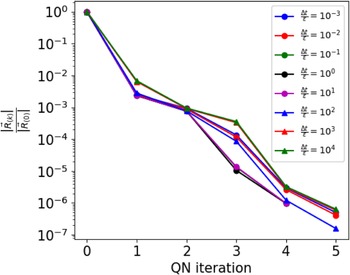


 Open access

