


1 Introduction
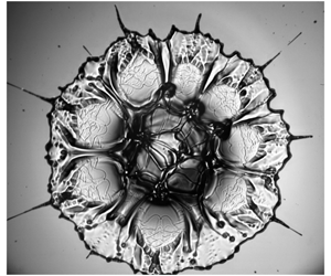
The study of drops impacting a solid surface is important for soil erosion, in ink-jet printing, for coating, cooling and cleaning of surfaces, as well as in combustion and numerous other industrial processes – see reviews by Yarin (Reference Yarin2006) and Josserand & Thoroddsen (Reference Josserand and Thoroddsen2016). Impacts are characterized by a rapid lamellar jet travelling along the solid substrate. This lamella remains axisymmetric, until at larger Reynolds numbers it starts splashing droplets through azimuthal instability (Rioboo et al. Reference Rioboo, Marengo and Tropea2002; Thoroddsen et al. Reference Thoroddsen, Takehara and Etoh2012; Riboux & Gordillo Reference Riboux and Gordillo2014; Roisman et al. Reference Roisman, Lembach and Tropea2015) or a levitated edge for more viscous liquids (Driscoll et al. Reference Driscoll, Stevens and Nagel2010; Schroll et al. Reference Schroll, Josserand, Zaleski and Zhang2010; Thoroddsen et al. Reference Thoroddsen, Takehara and Etoh2010). Splashing is also affected by the substrate properties (Deegan et al. Reference Deegan, Brunet and Eggers2008; Villermaux & Bossa Reference Villermaux and Bossa2011; Bird et al. Reference Bird, Dhiman, Kwon and Varanasi2013; Howland et al. Reference Howland, Antkowiak, Castrejon-Pita, Howison, Oliver, Style and Castrejon-Pita2016; Latka et al. Reference Latka, Boelens, Nagel and de Pablo2018; Wang & Bourouiba Reference Wang and Bourouiba2018). Here we break the axisymmetry by impacting a compound drop, which contains a number of smaller immiscible droplets inside. These smaller droplets are inserted using a microfluidic device, in a manner where we can control their size, number and arrangement. These internal droplets break the symmetry, which focuses kinetic energy into isolated thin jets, as shown in figure 1.
Prunet-Foch et al. (Reference Prunet-Foch, Legay, Vignes-Adler and Delmotte1998) studied the impact of fine emulsion droplets onto steel surfaces of various roughnesses, of relevance to spray cooling during metal forming. Their snapshot images showed fine jetting without imaging the detailed dynamics. This occurs when the small internal droplets are heavier than the continuous phase of the larger drop.
Recent studies by Liu et al. (Reference Liu, Zhang, Gao, Lu and Ding2018) have looked at the impact of compound drops in different configurations from those herein, where there is only one large internal droplet, of similar size to the primary drop. Here the larger drop essentially forms a shell around the inner droplet, i.e. the configuration remains axisymmetric. The axisymmetry allows well-resolved numerical simulations of these impacts, showing two spreading regimes of jammed spreading and joint-rim formation. However, the axisymmetry of the configuration excludes the focused jetting studied herein.
Gulyaev & Solonenko (Reference Gulyaev and Solonenko2013) similarly studied experimentally the bubble-in-drop configuration, showing a counter-jet rising vertically along the centreline. Li et al. (Reference Li, Duan, Zheng and Liu2018) have studied the corresponding heat transfer.
Examples of the jetting during the impact of a 2 cP water–glycerine drop that contains 20 smaller immiscible perfluorohexane (PP1) droplets. The outer drop diameter is  $D=3.8$ mm. The impact height is $H=100$ cm, giving $Re_{d}\simeq 8000$ and $We_{d}\simeq 2300$. The times shown are $t\simeq 0.04$, 0.12, 0.29 and 0.96 ms after first contact. See also supplementary movie 1 available at https://doi.org/10.1017/jfm.2019.885.

Figure 1 highlights the complexity, but also the repeatability of these jets. Note the eightfold repeated patterns around the shape in the last frame. The third image also shows some micro-splashing, which occurs at random locations around the lamellar edge, see Thoroddsen et al. (Reference Thoroddsen, Takehara and Etoh2012). The jetting shows two classes: the first is very fine and at the highest speeds; the second is broader, showing up with a triangular base in the third panel. The earliest jets are much faster than the regular impact-driven lamella and their thickness is only a tenth of the diameter of the inner droplets. Both of these observations demand a local focusing mechanism, which we will explain herein.
2 Experimental set-up
2.1 Imaging set-up
We use high-speed movie imaging to observe the details of the jetting through a substrate glass slide, as sketched in figure 2(a). A long-distance microscope (Leica Z16 APO) is used at up to  $1.75~\unicode[STIX]{x03BC}\text{m}~\text{px}^{-1}$. The illumination is from the top through the drop. Refraction through the numerous curved interfaces obscures the imaging, especially with many internal droplets present. This usually prohibits detailed mapping of the internal droplet arrangement.
For overall views, we use a Phantom V1611 complementary metal oxide semiconductor (CMOS) camera capable of 16 thousand frames per second (kfps) at full-frame resolution, which we use at reduced pixel area at up to 40 kfps; while for close-up images of the details, we employ a Kirana charge-coupled device (CCD) ultra-high-speed camera (Specialised Imaging, Tring, UK; see Crooks et al. (Reference Crooks, Marsh, Turchetta, Taylor, Chan, Lahav and Fenigstein2013)), which can acquire 180 frames at frame rates up to 5 million fps at maximum pixel resolution. Here we use up to 500 kfps. This camera has a dedicated red diode laser for each frame (SI-LUX640), with a dedicated line-camera trigger (SI-OT3), cut by the falling drop.
2.2 The emulsion liquids
The compound drops are produced in a microfluidic device, described in Li et al. (Reference Li, Zhang and Thoroddsen2013). The liquids we used are listed in table 1. Throughout this work we use the terminology of calling the entire liquid mass the ‘drop’, the smaller dispersed-phase spheres inside the drop are the ‘droplets’ and those droplets can break up into ‘satellites’. The subscripts  $d$ and $i$ indicate properties of the drop and inner droplets.
The inner liquid is perfluorohexane (PP1 from Flutec), which has a much higher density, of  $\unicode[STIX]{x1D70C}_{i}=1710~\text{kg}~\text{m}^{-3}$, than the various concentrations of the outer continuous-phase water–glycerine liquid, $\unicode[STIX]{x1D70C}_{d}=1000{-}1200~\text{kg}~\text{m}^{-3}$. The density difference is therefore up to $\unicode[STIX]{x0394}\unicode[STIX]{x1D70C}=\unicode[STIX]{x1D70C}_{i}-\unicode[STIX]{x1D70C}_{d}\leqslant 710~\text{kg}~\text{m}^{-3}$. In § 3.5 we add sodium iodide salt (NaI) to the outer phase to reduce $\unicode[STIX]{x0394}\unicode[STIX]{x1D70C}$. Larger concentrations of the glycerine increase the continuous-phase viscosity to between 2 and 500 cP. To stabilize the inside PP1 droplets and prevent their coalescence, we needed to add surfactant to the water–glycerine solution, 0.5–1.0 wt % Tween 20. The number of inner droplets is denoted by $N$ and can be varied continuously up to approximately $N\sim 20$ and even above that to fill the whole outer drop. Their arrangement at the bottom of the drop around the centre can occur in a reproducible manner for low values of $N$. The surface tension of the water–glycerine–surfactant mixtures against air is $\unicode[STIX]{x1D70E}_{d}\simeq 34~\text{mN}~\text{m}^{-1}$, while the interfacial tension between PP1 and the water–glycerine–surfactant mixtures has values of $\unicode[STIX]{x1D70E}_{i}\sim 28~\text{mN}~\text{m}^{-1}$.
(a) Sketch of the experimental and imaging set-up. (b) Side view of the falling compound drop, for 3.4 mm diameter outer drop of 20 cP with  $N=23$ PP1 droplets inside, impacting at $U=1.8~\text{m}~\text{s}^{-1}$, giving $Re_{d}\simeq 350$ and $We_{d}\simeq 370$. (c) Bottom close-up view showing inner droplets and one dimple, where the inner droplet is closest to the outer drop surface, forming a thin film between the two interfaces. The image is in free fall just prior to the impact on the solid surface.

Summary of liquids used in our experiments.

We keep the relative droplet size close to constant in most of the experiments, with the inner droplets  $d_{i}\sim 600{-}750~\unicode[STIX]{x03BC}\text{m}$, while the outer drop has a diameter of $D_{d}\sim 3.5{-}4.1$ mm, i.e. a size ratio of $6:1$. In § 3.4 we change the size of the inner droplets. Figure 2(b) and later figure 8 show that the inner droplets do not visibly deform the outer drop surface, unless $N$ becomes very large and starts crowding the available volume.
The drops are larger than the capillary length  $a=\sqrt{\unicode[STIX]{x1D70E}_{d}/(\unicode[STIX]{x1D70C}g)}\simeq 1.7$ mm. Therefore the drops are deformed and can oscillate after the pinch-off from the nozzle. However, the large viscosity of the outer liquid quickly dampens such oscillations and the observed deviations from spherical shape at impact are minimal.
The impact velocity  $U$ is varied by changing the release height $H$ up to 1.3 m, resulting in impact velocities of up to $5~\text{m}~\text{s}^{-1}$. This gives overall impact Reynolds and Weber numbers, based on the outer drop properties, in the ranges
 $$\begin{eqnarray}Re_{d}=\frac{\unicode[STIX]{x1D70C}_{d}D_{d}U}{\unicode[STIX]{x1D707}_{d}}=10{-}9500,\quad We_{d}=\frac{\unicode[STIX]{x1D70C}_{d}D_{d}U^{2}}{\unicode[STIX]{x1D70E}_{d}}=80{-}3800.\end{eqnarray}$$
 The capillary number relevant to the deformation of the inner droplets by the viscous stress in the continuous-phase liquid is  $Ca=\unicode[STIX]{x1D707}_{d}U/\unicode[STIX]{x1D70E}_{i}$.
2.3 Dimple size
In free fall the aerodynamic drag on the drop is minimal, at these small impact heights (see Thoraval et al. Reference Thoraval, Takehara, Etoh and Thoroddsen2013). Therefore, the added relative weight of the inner droplets does not need to be supported by the outer drop’s surface tension. On the other hand, during the minute-long feeding of the droplets from the microfluidic device, the pendent drop at the nozzle holds up the heavier internal droplets and the outer film drains at the bottom of each droplet, thinning out a small circular patch or dimple, which is visible in the images, as pointed out in figure 2(c). The size of this patch is set by the static conditions inside the pendent drop, as sketched in figure 3(a). The extra weight  $g\unicode[STIX]{x0394}\unicode[STIX]{x1D70C}(4\unicode[STIX]{x03C0}R_{i}^{3}/3)$ of the inner droplets must be supported by a capillary pressure produced by a deformation of the outer free surface. An inner droplet will therefore produce an outwards protrusion of the surface, bounded by a thin film of the outer liquid. The radial size of this dimple can be estimated by the balance between the extra weight and the increased capillary pressure $2\unicode[STIX]{x1D70E}_{o}/R_{p}$ over the area of the protrusion $\unicode[STIX]{x03C0}R_{dimple}^{2}$. Here $R_{p}$ is the radius of curvature of the protrusion, which differs from the radius of the inner drop $R_{i}$. Following the arguments in Toba (Reference Toba1959) and Lhuissier & Villermaux (Reference Lhuissier and Villermaux2012), for a bubble floating under a flat pool surface, the curvature of the protrusion is half that of the inner droplet, i.e. $R_{p}=2R_{i}$, owing to the double interface at the protrusion. Here the two surface tensions are slightly different, but similar arguments apply, i.e. $\unicode[STIX]{x1D70E}_{i}/R_{i}=(\unicode[STIX]{x1D70E}_{i}+\unicode[STIX]{x1D70E}_{d})/R_{p}$. Therefore, the balance
 $$\begin{eqnarray}\frac{4}{3}\unicode[STIX]{x03C0}R_{i}^{3}\,\unicode[STIX]{x0394}\unicode[STIX]{x1D70C}\,g=\frac{2\unicode[STIX]{x1D70E}_{d}}{R_{p}}\unicode[STIX]{x03C0}R_{dimple}^{2}\end{eqnarray}$$
finally gives a dimple size
 $$\begin{eqnarray}R_{dimple}=R_{i}^{2}\sqrt{\frac{2\,\unicode[STIX]{x0394}\unicode[STIX]{x1D70C}g\cos \unicode[STIX]{x1D703}}{3}\frac{(\unicode[STIX]{x1D70E}_{i}+\unicode[STIX]{x1D70E}_{d})}{\unicode[STIX]{x1D70E}_{i}\,\unicode[STIX]{x1D70E}_{d}}}.\end{eqnarray}$$
However, in free fall, as stated above, the inner and outer drops accelerate at the same rate, assuming the air drag is minimal. The outer surface can therefore relax to approach its spherical form. This, however, leaves the imprinted dimple or patch marking the thin drainage film between the two curved surfaces. Liquid should eventually be pulled into this thin gap, but the short time of free fall is insufficient to equilibrate this shape.
(a) Sketch of the force balance for the drop pendent at the nozzle before release. (b) Dimple sizes for different  $\unicode[STIX]{x0394}\unicode[STIX]{x1D70C}$ between the two liquids. (c) The measured dimple sizes versus the predicted size from (2.3). The black squares are for different inner droplet sizes for $\unicode[STIX]{x0394}\unicode[STIX]{x1D70C}=570~\text{kg}~\text{m}^{-3}$ and the red circle for the minimum $\unicode[STIX]{x0394}\unicode[STIX]{x1D70C}=90~\text{kg}~\text{m}^{-3}$.

Figure 3(c) shows dimple-size results for a range of inner droplet sizes for  $d_{i}$ between $424~\unicode[STIX]{x03BC}\text{m}$ and $739~\unicode[STIX]{x03BC}\text{m}$. It also includes a dimple for a smaller value for $\unicode[STIX]{x0394}\unicode[STIX]{x1D70C}$. The predictions follow the same trend as the proposed scaling, but the observed dimples are consistently approximately 1.5 times larger. This can be partly explained by the larger area of the bump than the flatter drop surface. Figure 3(c) is for isolated droplets, but, for a large number of inner droplets, they will arrange in multiple layers and the dimples must support larger weights, increasing their size and the width of the corresponding dimples and jets.
Keep in mind that the term ‘dimple’ does not indicate that we know the geometry of this patch of thin liquid between the inner droplet and the outer drop free surface. The images do not show a bump or a protrusion and the relaxation of the thickness shape is beyond our current imaging technique.
3 Results
Examples of the jetting during impact of compound drops. (a) A 4.1 mm outer drop of 5 cP water–glycerine that contains five inner PP1 droplets: a symmetric layer of four along the bottom surface with the fifth above them at the centre. The image shows that each of the three visible jets is aligned with an inner droplet. The images are 0, 1.2 and 13.8 ms after first contact with the solid; here  $Re_{d}=3120$ and $We_{d}=1560$. The scale bar is 1 mm long. (b) High-viscosity 3.4 mm drop of 200 cP at $U=4.3~\text{m}~\text{s}^{-1}$, fully loaded with more than 20 inner droplets; here $Re_{d}=90$ and $We_{d}=2280$. To prevent coalescence of the internal droplets, we have added 1 % of Tween surfactant. Times shown are 0.08, 0.33 and 2.3 ms after first contact. See supplementary movies 2 and 3.

Figures 1 and 4 show examples of the very fine radial jets that are produced immediately following the first contact. Figure 4(a) shows that these jets are perfectly aligned with the internal droplets. The jets are  $38~\unicode[STIX]{x03BC}\text{m}$ wide and emerge at $U_{j}=23~\text{m}~\text{s}^{-1}$. These jets are clearly levitated above the solid surface, and when they are observed to touch it, they stop immediately from the viscous stress. Figure 4(a) also shows clearly how the inner droplets are stretched out into convoluted pancake structures at the later stage of the impact. The internal droplets have a spherical diameter of $770~\unicode[STIX]{x03BC}\text{m}$, while in the last panel of figure 4(a), their projected area has increased approximately tenfold, suggesting a thickness less than $70~\unicode[STIX]{x03BC}\text{m}$.
Figure 4(b) shows a much more viscous continuous-phase drop ( $\unicode[STIX]{x1D707}_{d}=200$ cP), with a large number of internal droplets, $N>20$. Here the jetting is less regular, but the first jets are approximately the same thickness and velocity as for the lower viscosity in figure 4(a). The first four jets are approximately $30~\unicode[STIX]{x03BC}\text{m}$ in diameter and emerge at $U_{j}\simeq 21~\text{m}~\text{s}^{-1}$. Ten more jets appear approximately $80~\unicode[STIX]{x03BC}\text{s}$ later and these are slightly thicker, ${\sim}70~\unicode[STIX]{x03BC}\text{m}$, and slower, $U_{j}\simeq 12~\text{m}~\text{s}^{-1}$. The bases of these secondary jets form wetting fingers in the last panel of figure 4(b).
The emergence of jetting at the base of an inner droplet. (a) The black arrows in the third frame point to the two tips of the flat jet squeezed around and under the dimple of the inner droplet, for  $\unicode[STIX]{x1D707}_{d}=20$ cP, with $N=6$ and $U=0.83~\text{m}~\text{s}^{-1}$, giving $Re_{d}\simeq 170$ and $We_{d}\simeq 82$. The arrow in the second frame points out the rapidly moving contact line, which comes from the bottom right. The dimple in the first frame is $110~\unicode[STIX]{x03BC}\text{m}$ across, while the width of the sheet between the arrows in the third frame is slightly wider, at $130~\unicode[STIX]{x03BC}\text{m}$. The speed of the tip of the ejected sheet, between the second and fourth frames, is ${\sim}14~\text{m}~\text{s}^{-1}$. The tip of the jet has already left the illuminated region at $50~\unicode[STIX]{x03BC}\text{s}$, far ahead of the contact line (arrow). (b) Same liquid as above, but for larger $U=4.0~\text{m}~\text{s}^{-1}$ ( $Re_{d}\simeq 810$, $We_{d}\simeq 1910$). The ejection speed is correspondingly much larger at ${\sim}36~\text{m}~\text{s}^{-1}$. The $5~\unicode[STIX]{x03BC}\text{s}$ exposure time causes some motion smearing.

3.1 Jetting mechanism
The fact that the jets are perfectly aligned with the centres of the internal droplets suggests that they play a central role in a local generation mechanism. We have therefore focused imaging on isolated droplets. Figure 5 shows two examples of the overall flow around an inner droplet and the onset of jetting. The jet emerges when the impact-driven contact line moves past the dimple, where the droplet sits closest to the outer surface of the drop. It forms as a thin horizontal sheet, only slightly wider than the diameter of this dimple. Within a few microseconds the sheet has converged into a narrow cylindrical jet, visible in the previous figures. Figure 6(a) shows a close-up of this interaction of the contact line with the dimple, at  $2~\unicode[STIX]{x03BC}\text{s}$ time resolution and a larger optical magnification. This shows the flat jetting occurring exactly when the contact line passes through the dimple. The jets move above the solid surface, when they emerge from the drop in figures 1 and 4. Viscous forces would prevent such thin fast-moving jets from being in contact with the solid. This is also the case for the thin narrow sheet, as its edge can be traced along the leading edge of a levitated tip of the lamella, pointed out by the black arrows in figure 6(a). The close-up side views in figure 8 confirm this levitation. We also note that the contact line in figures 6(a) and 7(a) are continuous below this sheet, supporting it being levitated above the solid surface.
(a) Close-up of the jet formation, for  $\unicode[STIX]{x1D707}_{d}=5$ cP, $N=5$ and $U=2.8~\text{m}~\text{s}^{-1}$ ( $Re_{d}\simeq 2100$, $We_{d}\simeq 860$). (b) Formation of the jet from the ejected horizontal sheet for the largest drop viscosity $\unicode[STIX]{x1D707}_{d}=500$ cP, $N=5$ and $U=3.4~\text{m}~\text{s}^{-1}$. The jet diameter here is only $34~\unicode[STIX]{x03BC}\text{m}$ ( $Re_{d}\simeq 30$, $We_{d}\simeq 1450$). (c) Sketch of the pressure-driven flow-focusing mechanism between the solid and the droplet.

(a) Radial motions versus time immediately following first contact, tracked from a 500 kfps movie clip. The drop-liquid viscosity is  $\unicode[STIX]{x1D707}_{d}=5$ cP, $U=3.1~\text{m}~\text{s}^{-1}$, giving $Re_{d}\simeq 2340$ and $We_{d}\simeq 1080$. (b) The black squares mark the contact line, red circles represent the edge of the levitated lamella and blue triangles show the tip of the fine jet, until it reaches the edge of the frame. The black line is the theoretical fit, based on (3.1), with $t_{o}=1.5~\unicode[STIX]{x03BC}\text{s}$ and $C=1.02$. The green stars show the edge of the contracting central entrapped air disc, constructed from a second 500 kfps realization.

How is this thin sheet ejected? We propose that it is simply pressure-driven flow into the converging wedge between the solid and the internal droplet, as we sketch in figure 6(c). The droplet has 70 % higher density than the surrounding liquid and is therefore not accelerated radially as fast as the drop liquid, acting as a boundary. Keep in mind that the strongest focusing occurs under the centre of the droplet, where the gap is narrowest; this is indeed where the thin sheet emerges. The heavier inner droplet also helps to squeeze out the underlying lighter liquid. The boundary condition on the droplet surface is also important, especially when the continuous-phase viscosity becomes large. For the 200 cP liquid in figure 6(b), the capillary number is quite large,  $Ca\simeq 80$. Here the dynamics could pull some of the droplet liquid into the jet.
Balancing the liquid volume of the sheet with the resulting jet suggests that the sheet is less than a micrometre thick. It is therefore quickly pulled together by surface tension, while the geometry may also provide horizontally convergent flow downstream of the dimple.
In figure 7(b) we have tracked the early motion of the contact line, during the formation of the jet. It shows the continued rapid deceleration of the contact line, while the jet emerges at constant velocity, quickly overtaking it. The radial location of the contact line itself,  $R(t)$, follows closely the inviscid theory (Korobkin & Scolan Reference Korobkin and Scolan2006; Riboux & Gordillo Reference Riboux and Gordillo2014; Philippi et al. Reference Philippi, Lagree and Antkowiak2016),
 $$\begin{eqnarray}\frac{R(t)}{R_{b}}=\sqrt{\frac{3tU}{D_{d}/2}},\end{eqnarray}$$
 which is included in figure 7(b). Here  $R_{b}$ is the bottom radius of curvature of the drop. We have shifted the time axis by $t_{o}$ to account for the drop deformation before first contact at $t=0$. Following Li et al. (Reference Li, Thoraval, Marston and Thoroddsen2018), the normalized radius $R/R_{b}=r(\unicode[STIX]{x1D70F})=C\sqrt{3\unicode[STIX]{x1D70F}}$, where the time is normalized as $\unicode[STIX]{x1D70F}=(t-t_{o})U/R_{b}$. Here the best fit has $C=1.02$, which is close to the theoretically predicted value of unity.
3.2 Jetting speed
In figure 4 it was observed that the speed of the fastest early jets is essentially the same for 5 and 200 cP drop viscosities. In figure 9 we quantify this velocity over a range of continuous-phase viscosities, while the inner droplets are of the same low-viscosity PP1 liquid. Only at the largest viscosity of 500 cP do the jets slow down significantly. If we approximate this transition to viscous effects at  ${\sim}300$ cP, that corresponds to $Re_{d}\sim 40$. Furthermore, the diameter of the jets remains rather unaffected, as shown in figure 9(b). These results support inertial focusing of the jets.
Comparison of the impact (a) without inner droplets and (b) with  $N=4$ internal droplets. The 3.7 mm diameter drop is of 10 cP water–glycerine mixture, impacting at $3.2~\text{m}~\text{s}^{-1}$, giving $Re_{d}\simeq 1370$ and $We_{d}\simeq 1290$. The scale and times in both sequences are the same. The arrow points out the micro-jet emerging near the substrate. The dashed circles show the approximate size of the inner droplets. The inverted image is the reflection from the glass surface.

(a) Jetting velocity versus the viscosity of the outer liquid. The drop liquid is a water–glycerine mixture with between 40 % and 95 % glycerine to vary  $\unicode[STIX]{x1D707}_{d}$ from 5 to 500 cP, while the inner $N=5$ droplets are PP1. The impact velocity is kept constant at $U=3.4~\text{m}~\text{s}^{-1}$. (b) The thickness of the earliest, thinnest jets.

3.3 Jetting threshold
In figure 10(a) we systematically increase the impact velocity, for fixed droplet number  $N=6$, to pinpoint where the jetting inertia overcomes the viscous stress and the drop–air surface tension $\unicode[STIX]{x1D70E}_{d}$. The onset of jetting is seen at $Re_{d}\simeq 230$. This is determined from approximately a dozen impacts for each release height, and the variability arises from the changes in droplet arrangement within the drop, which is not fully controllable. We therefore present the probability of jetting.
In a second set of experiments we systematically vary the number  $N$ of inner droplets, while keeping the impact velocity constant, as reported in figure 10(b). Here we observe no jetting for the axisymmetric case of one inner drop. Also for two drops the drops appear to be too close to the centreline; perhaps the edge of the central air disc trapped under the drop (Li & Thoroddsen Reference Li and Thoroddsen2015; Hendrix et al. Reference Hendrix, Bouwhuis, Van Der Meer, Lohse and Snoeijer2016; Li et al. Reference Li, Langley, Tian, Hicks and Thoroddsen2017) reaches too close to the location of the inner droplet dimple (see § 3.4). For $N=3$ some infrequent jetting is observed, while for $N\geqslant 4$ most realizations have strong jetting.
However, for a large number of droplets  $N>11$ apparent crowding effects begin and less jetting is observed. Conceptually, we suggest that the large number of internal surfaces creates resistance to large-scale drop deformations and slows down the lamella, stopping our jetting mechanism.
(a) Onset of jetting for drop liquid viscosity of 20 cP and  $N=6$, over a range of impact velocities, in terms of $Re_{d}$. (b) Probability of jetting for a different number of inner droplets $N$, while fixing the impact velocity at $U=1.15~\text{m}~\text{s}^{-1}$.

Our proposed jetting mechanism should be sensitive to the size of the inner droplets. It also depends crucially on the larger density of the inside droplets, to allow forced focusing of the outer liquid in the wedge under these droplets. In the next two subsections we will vary these factors to support our proposal.
3.4 Effect of size and radial location of inner droplets
Wide sheets emerge from under two large internal droplets  $d_{i}=1370~\unicode[STIX]{x03BC}\text{m}$, inside a $D=4.0~\text{mm}$ drop of 10 cP water–glycerine solution, impacting at $U=3.1~\text{m}~\text{s}^{-1}$, giving $Re_{d}\simeq 1430$ and $We_{d}\simeq 1310$. (a) Bottom view at $t=128~\unicode[STIX]{x03BC}\text{s}$ after first contact. (b,c) Angled view from top at $t=0.68$ and 1.84 ms, respectively.

Figure 11 shows the jetting for two very large inner droplets,  $d_{i}=1370~\unicode[STIX]{x03BC}\text{m}$, which is approximately twice the size of the inner droplets used above. Here the thin sheet is too wide to contract from the sides into a columnar jet; rather, it breaks up, leaving two filaments at its edges. Figure 11(c) shows the two flattened droplets spread near the substrate.
Figure 12 shows jetting for the smallest internal droplets of  $d_{i}=424~\unicode[STIX]{x03BC}\text{m}$, but with a different number of them. For $N=4$ (figure 12a), the droplets sit very close to the axis of symmetry. In this particular case, they are not aligned in a perfectly symmetric way, with one of them slightly further from the axis, and only for that droplet is jetting observed, as pointed out by the white arrow. This jet is only ${\sim}8~\unicode[STIX]{x03BC}\text{m}$ across. The small droplet size makes the dimple smaller (see (2.3)) and, as predicted, the jet is very thin. For a larger number of internal droplets, $N=13$ and 17 (figure 12b,c), the droplets must get arranged further from the axis and numerous jets are observed, with $N_{jets}=8$ and 12, respectively.
Influence of droplet location on jetting for small internal droplets  $d_{i}\simeq 424~\unicode[STIX]{x03BC}\text{m}$, for a $D_{d}=4.06$ mm drop of 10 cP water–glycerine solution, impacting at $U=3.16~\text{m}~\text{s}^{-1}$, giving $Re_{d}\simeq 1480$ and $We_{d}\simeq 1380$. Panels show bottom views: (a) $N=4$ shown at $t=76~\unicode[STIX]{x03BC}\text{s}$ after first contact; (b) $N=13$ at $t=134~\unicode[STIX]{x03BC}\text{s}$; and (c) $N=17$ at $t=128~\unicode[STIX]{x03BC}\text{s}$.

3.5 Effect of density difference
Conceptually, for our jetting mechanism to work, the inner droplets must be significantly heavier than the continuous phase for it to be focused into the wedge under the droplet, to form the jet. To verify the significance of the density difference between the two liquids, we add sodium iodide salt (NaI) to the continuous-phase water–glycerine solution, to reduce  $\unicode[STIX]{x0394}\unicode[STIX]{x1D70C}$ from 580 to $90~\text{kg}~\text{m}^{-3}$. This was done in stages for the same internal droplet size and arrangement. Figure 3(b) showed that the dimple reduces greatly in size with this reduction in $\unicode[STIX]{x0394}\unicode[STIX]{x1D70C}$. Figure 13 shows that the jetting also disappears for greatly reduced value of $\unicode[STIX]{x0394}\unicode[STIX]{x1D70C}$. Here we use two regular size inner droplets $d_{i}=740~\unicode[STIX]{x03BC}\text{m}$, which was shown to produce two jets in opposite directions for the density difference in the previous set-up of $\unicode[STIX]{x0394}\unicode[STIX]{x1D70C}=570~\text{kg}~\text{m}^{-3}$. The jetting persists for $\unicode[STIX]{x0394}\unicode[STIX]{x1D70C}=190~\text{kg}~\text{m}^{-3}$ in figure 13(a), but disappears entirely for $\unicode[STIX]{x0394}\unicode[STIX]{x1D70C}=90~\text{kg}~\text{m}^{-3}$, as seen in figure 13(b).
Jetting disappears when  $\unicode[STIX]{x0394}\unicode[STIX]{x1D70C}$ is greatly reduced. (a) Jetting for $\unicode[STIX]{x1D70C}_{\ell }=1520~\text{kg}~\text{m}^{-3}$, giving $\unicode[STIX]{x0394}\unicode[STIX]{x1D70C}=190~\text{kg}~\text{m}^{-3}$, shown at $t=124~\unicode[STIX]{x03BC}\text{s}$. (b) No jetting for $\unicode[STIX]{x1D70C}_{\ell }=1620~\text{kg}~\text{m}^{-3}$, $\unicode[STIX]{x0394}\unicode[STIX]{x1D70C}=90~\text{kg}~\text{m}^{-3}$, at $t=174~\unicode[STIX]{x03BC}\text{s}$. Even at this later time the lamellar edge remains smooth. Impact conditions are similar to those in figure 12.

3.6 Deformation and breakup of the inner droplets
The large deformations of the droplets can result in their breakup, in many convoluted ways (Lhuissier et al. Reference Lhuissier, Sun, Prosperetti and Lohse2013), when the interfacial tension cannot prevent the large impact-driven motions. The sequences in figures 14 and 15 show tendrils pulled out of the lower section of the droplets closest to the solid. These tendrils subsequently break by Rayleigh capillary instability or tip streaming. Note the identical pattern of the sub-satellites from the thread pulled out from all four droplets in figure 14(a). Each thread leaves two  $d_{s}\simeq 150~\unicode[STIX]{x03BC}\text{m}$ satellites, one $70~\unicode[STIX]{x03BC}\text{m}$, one $40~\unicode[STIX]{x03BC}\text{m}$, and even finer threads are visible between them, which have likely broken into a multitude of micrometre-sized droplets. They are too small to resolve in this optical magnification. The diffuse dark shadows mark the extent of the flattened PP1 droplets, away from the solid, where they are out of focus. The sharper bright ellipses mark the edge of the regions where the droplets are closest to the substrate, while it is probably not a contact line. For less viscous outer liquid, shown in figure 14(b), the central droplet is ripped apart, first to form a prominent $\times$ shape, which breaks into multiple smaller satellites.
Figure 15 shows the changes in the breakup shapes as the impact  $Re_{d}$ is changed, while the PP1 droplets are unchanged. For the lowest outer viscosity, the leading edge of the droplets forms multiple fingers, while larger drop viscosity reduces the finger numbers, but extends a tail towards the centre. These tails are also visible for 10 cP and subsequently break up by tip streaming, as shown in the supplementary movies. For 20 cP the droplets remain essentially intact, for this low $Re_{d}$.
4 Conclusions
The presence of the interior droplets causes localized accelerations and thereby greatly enhances splashing. Based on the properties of the outer drop, the value of the splashing parameter  $K=We\sqrt{Re}$, where we see these jets start, for $\unicode[STIX]{x1D707}_{d}=20$ cP in figure 4(a), is at $K\sim 1000$, which is much lower than the typical values of $K\sim 3000$ for pure drops (Josserand & Thoroddsen Reference Josserand and Thoroddsen2016). Furthermore, the speed of the micro-jets is eight times the drop impact velocity, which is much faster than the lamella for comparable $Re_{d}$. This will enhance levitation of the splashed droplets, which is of practical importance in some applications.
The early work of Prunet-Foch et al. (Reference Prunet-Foch, Legay, Vignes-Adler and Delmotte1998) observed some radial jetting for impacts of droplets of oil-in-water emulsions, but without time-resolved imaging. They have proposed a jetting mechanism for their case, where the two liquids are of similar densities, with the dispersed oil phase slightly heavier by  $\unicode[STIX]{x0394}\unicode[STIX]{x1D70C}\simeq 10~\text{kg}~\text{m}^{-3}$. They attribute the fine jets to the heavier droplets being ejected out of the drop surface and dragging a tail behind them. This must occur during the deceleration phase of the free surface and differs qualitatively from our observed flow of the outer lighter continuous phase around the heavier internal droplets.
Hydrodynamic focusing for penetration into nanofibre mats has been demonstrated experimentally and theoretically by Sahu et al. (Reference Sahu, Sett, Yarin and Pourdeyhimi2015), but in their configuration the incoming velocity is uniform.
Jetting and subsequent deformation of the five inner droplets of PP1. (a) For an outer liquid of 10 cP, tendrils are pulled from the back side of the droplets. The impact velocity is  $U=2.0~\text{m}~\text{s}^{-1}$, giving $Re_{d}\simeq 790$ and $We_{d}\simeq 460$. Times shown are $t=0.22$, 2.6, 3.8 and 5.8 ms after first contact. (b) For less viscous outer liquid of 2 cP, at $U=4.0~\text{m}~\text{s}^{-1}$, the central drop is pulled apart. Times shown are $t=0.11$, 0.81, 1.6 and 3.2 ms after first contact. Here $Re_{d}\simeq 8100$ and $We_{d}\simeq 1900$. The scale bars are both 1 mm long. See also the supplementary movies.

Questions remain in this very rich impact configuration. The jetting speed should be affected by the radial location of the inner droplets, as the speed of the contact line reduces rapidly with time, i.e.  $\text{d}r(t)/\text{d}t$. Studying this will require systematically varying the size of the inner droplets.
Is some of the droplet liquid pulled along into the jet? This could occur for larger  $\unicode[STIX]{x1D707}_{d}$ and $Ca_{d}$. The last frames in figure 5 indicate disruptive interaction at the interface. In some rare cases, we note some isolated microdroplets from the tip of the jets (see for example figure 13a). The jets are pure continuous phase. This is clear from the fact that they do not break up rapidly from Rayleigh instability, as would occur for the low-viscosity PP1.
Finally, a crucial aspect of our jet-focusing mechanism is the larger density of the inside droplets. By increasing the density of the outer liquid, we have shown that jetting stops when  $\unicode[STIX]{x0394}\unicode[STIX]{x1D70C}$ becomes small. In other words, the wedge is maintained by the added inertia of the inner droplet interface. Interfacial tension will also help to maintain this boundary, but is not a primary factor, as is clear in §§ 3.5 and 3.6. The details of the impulse-induced radial flow near the substrate will also be important in the focusing. Figure 4(c,e) in the study by Philippi et al. (Reference Philippi, Lagree and Antkowiak2016) is instructive. It shows the early radial flow near the base of the ejecta, even though they ignore the central air disc and the associated radial flow near the kink at the edge of this dimple (see figures 2 and 5 in Mandre & Brenner (Reference Mandre and Brenner2012)). Fully three-dimensional numerical simulations of this phenomenon may be needed to quantify this aspect of the focusing in the wedge. Further studies are also needed to quantify the critical $\unicode[STIX]{x0394}\unicode[STIX]{x1D70C}$ and the viscosity of the outer phase. Jetting from multiple layers of inner droplets will also lead to further complexity, as hinted at in figure 1.
Typical examples of droplet deformation and breakup for  $N=6$ or 7, as the outer drop viscosity is increased from left to right: (a) 2, (b) 5, (c) 10 and (d) 20 cP. The corresponding $Re_{d}$ and $We_{d}$ are: $(8500,1100)$, $(2700,740)$, $(590,150)$ and $(220,88)$. The resulting satellites are shown in the lower row. This is driven by capillary pinch-off of the central droplet (on the far left) and after tip streaming from the outer droplets in the middle two panels. Here, the most viscous continuous phase, on the far right, does not leave central satellites, only a small one near the outer drop contact line (marked by an arrow). The underlying movie clips are included in the supplementary movies.

Acknowledgements
The work described herein was supported by King Abdullah University of Science and Technology (KAUST) research funding (URF/1/2621-01-01 and URF/1/3727-01-01). Some of the supplementary movies were submitted to the Gallery of Fluid Motions of the APS-DFD meeting held in San Francisco in November 2014 (V0042, https://doi.org/10.1103/APS.DFD.2014.GFM.V0042). E.Q.L. acknowledges the Thousand Young Talents Program of China, the National Natural Science Foundation of China (grants nos 11772327, 11972339 and 11621202) and Fundamental Research Funds for the Central Universities (grant no. WK2090050041). E.Q.L. also acknowledges Dr Y. Jin and the Experimental Center of Engineering and Material Sciences at University of Science and Technology of China for using their Kirana camera at the revision stage of the manuscript. The authors thank Professor A. Marin of the University of Twente for valuable assistance.
Supplementary movies
Supplementary movies are available at https://doi.org/10.1017/jfm.2019.885.


 Open access