





1. Introduction
FERMI was the first free-electron laser (FEL) facility where external seeding was implemented. It is based on the high-gain harmonic generation (HGHG) seeding scheme[ Reference Yu, Babzien, Ben-Zvi, DiMauro, Doyuran, Graves, Johnson, Krinsky, Malone, Pogorelsky, Skaritka, Rakowsky, Solomon, Wang, Woodle, Yakimenko, Biedron, Galayda, Gluskin, Jagger, Sajaev and Vasserman 1 ]. The initially planned FERMI wavelength ranges of 40–100 nm in single-cascade (FEL1)[ Reference Allaria, Appio, Badano, Barletta, Bassanese, Biedron, Borga, Busetto, Castronovo, Cinquegrana, Cleva, Cocco, Cornacchia, Craievich, Cudin, D’Auria, Dal Forno, Danailov, De Monte, De Ninno, Delgiusto, Demidovich, Di Mitri, Diviacco, Fabris, Fabris, Fawley, Ferianis, Ferrari, Ferry, Froehlich, Furlan, Gaio, Gelmetti, Giannessi, Giannini, Gobessi, Ivanov, Karantzoulis, Lonza, Lutman, Mahieu, Milloch, Milton, Musardo, Nikolov, Noe, Parmigiani, Penco, Petronio, Pivetta, Predonzani, Rossi, Rumiz, Salom, Scafuri, Serpico, Sigalotti, Spampinati, Spezzani, Svandrlik, Svetina, Tazzari, Trovo, Umer, Vascotto, Veronese, Visintini, Zaccaria, Zangrando and Zangrando 2 ] and 10–40 nm in double-cascade fresh-bunch mode (FEL2)[ Reference Allaria, Castronovo, Cinquegrana, Craievich, Dal Forno, Danailov, D’Auria, Demidovich, De Ninno, Di Mitri, Diviacco, Fawley, Ferianis, Ferrari, Froehlich, Gaio, Gauthier, Giannessi, Ivanov, Mahieu, Mahne, Nikolov, Parmigiani, Penco, Raimondi, Scafuri, Serpico, Sigalotti, Spampinati, Spezzani, Svandrlik, Svetina, Trovo, Veronese, Zangrando and Zangrando 3 ] have been largely extended. At present, the facility typically operates in the ranges of 17–110 nm (FEL1) and 4–20 nm (FEL2). The laser system providing the external ultraviolet (UV) seed pulses required by the scheme was designed nearly 15 years ago and is entirely based on Ti:sapphire pumped infrared (IR) optical parametric amplifier (OPA) technology, at that time the only laser configuration allowing one to reach the needed parameters. Originally, a single CPA Ti:sapphire regenerative amplifier was used as a pump. The need for continuous improvement of the seed pulses for both FEL lines, and the high flexibility required (i.e., seed parameters optimized individually for nearly every beamtime) has driven the continuous development and improvements of the original configuration. FERMI’s presently unique pump–probe scheme based on a seed-laser-derived pulse delivered to the end-stations for pump–probe experiments allows a very tight synchronization of the FEL pulse to the seed[ Reference Cinquegrana, Cleva, Demidovich, Gaio, Ivanov, Kurdi, Nikolov, Sigalotti and Danailov 4 ]. This scheme provides nearly jitter-free pump–probe pulse pairs and has been an additional driver for constant improvement and increase of the complexity of the seed laser system. Here we describe the layout of the main laser system, including details on the HGHG seeding dedicated part. Timing synchronization, online diagnostics and feedbacks are essential for the successful user operation of the facility and are also addressed. The scheme used for delivering one part of the pulses generated by the seed laser system for pump–probe experiments has already been described elsewhere[ Reference Cinquegrana, Cleva, Demidovich, Gaio, Ivanov, Kurdi, Nikolov, Sigalotti and Danailov 4 , Reference Danailov, Bencivenga, Capotondi, Casolari, Cinquegrana, Demidovich, Giangrisostomi, Kiskinova, Kurdi, Manfredda, Masciovecchio, Mincigrucci, Nikolov, Pedersoli, Principi and Sigalotti 5 ]. It is briefly discussed here to the extent needed to understand better the laser system layout. The final part of the paper contains an outlook of the new seed laser system design needed for the implementation of the echo-enabled harmonic generation (EEHG) seeding scheme at FERMI.
2. Present seed laser system
2.1. Main requirements of the seed pulses in the HGHG scheme
The FEL emission in a self-amplified spontaneous emission (SASE) scheme starts from incoherent spontaneous emission noise. In contrast, in the HGHG seeding scheme, it is initiated by the well-defined modulation of a pre-bunched electron beam. To obtain this modulation, the accelerated electron bunch interacts with a sufficiently strong seed pulse in a short modulator undulator (see Figure 1(a)), resonant at the seed pulse wavelength[ Reference Yu, Babzien, Ben-Zvi, DiMauro, Doyuran, Graves, Johnson, Krinsky, Malone, Pogorelsky, Skaritka, Rakowsky, Solomon, Wang, Woodle, Yakimenko, Biedron, Galayda, Gluskin, Jagger, Sajaev and Vasserman 1 , Reference Allaria, Appio, Badano, Barletta, Bassanese, Biedron, Borga, Busetto, Castronovo, Cinquegrana, Cleva, Cocco, Cornacchia, Craievich, Cudin, D’Auria, Dal Forno, Danailov, De Monte, De Ninno, Delgiusto, Demidovich, Di Mitri, Diviacco, Fabris, Fabris, Fawley, Ferianis, Ferrari, Ferry, Froehlich, Furlan, Gaio, Gelmetti, Giannessi, Giannini, Gobessi, Ivanov, Karantzoulis, Lonza, Lutman, Mahieu, Milloch, Milton, Musardo, Nikolov, Noe, Parmigiani, Penco, Petronio, Pivetta, Predonzani, Rossi, Rumiz, Salom, Scafuri, Serpico, Sigalotti, Spampinati, Spezzani, Svandrlik, Svetina, Tazzari, Trovo, Umer, Vascotto, Veronese, Visintini, Zaccaria, Zangrando and Zangrando 2 ]. The resulting electron beam energy modulation is transformed into bunching at the harmonics of the seed wavelength λ by subsequently sending the electron beam through a dispersive section (DS). Finally, the microbunched electrons propagate through a chain of radiator undulators tuned at the nth harmonic of the seed wavelength and emit highly coherent FEL pulses at a wavelength λ/n. At a fixed electron energy, the FEL emission wavelength can be controlled by changing the seed wavelength and adjusting the undulator gaps to keep the resonance condition, as well as by switching the harmonic order at a fixed seed wavelength. A complete tunability over the full FEL range can be obtained by tailoring the tuning curves obtained at different harmonics. The fractional seed tunability required for having gap-free coverage is inversely proportional to the harmonic order:
 \begin{align}\Delta \lambda /\lambda \sim 2/\left(2n-1\right).\end{align}
This relation indicates that with a deep-UV (DUV) seed even at mid-range harmonic orders of, for example, six or seven, a continuous seed wavelength tuning of at least 40 nm is required.
HGHG seeding scheme at FERMI: (a) single stage, FEL1; (b) fresh-bunch double stage, FEL2. DS: dispersive section.

The FEL process is very well understood and can be simulated with high accuracy by different machine simulation codes. The campaign performed as a part of the FERMI design process indicated that harmonics up to n = 10–12 can be generated by the above-described layout. The generation of much higher harmonic orders (e.g., n = 45–60) by the HGHG scheme was, however, shown to be feasible only in the double-cascade mode, where the seeding process is repeated twice (see Figure 1(b))[ Reference Allaria, Castronovo, Cinquegrana, Craievich, Dal Forno, Danailov, D’Auria, Demidovich, De Ninno, Di Mitri, Diviacco, Fawley, Ferianis, Ferrari, Froehlich, Gaio, Gauthier, Giannessi, Ivanov, Mahieu, Mahne, Nikolov, Parmigiani, Penco, Raimondi, Scafuri, Serpico, Sigalotti, Spampinati, Spezzani, Svandrlik, Svetina, Trovo, Veronese, Zangrando and Zangrando 3 ]. The seed wavelength for FERMI has been chosen to be in the DUV/UV range of 230–360 nm, where up-converted OPA pulses offered sufficient tunability and could satisfy the requested pulse properties specified in Table 1. We note that the values listed in the table are the ones at the delivery point, that is, after a long and relatively complex beam transport imposed by the FERMI layout. Vacuum-UV (VUV) seeding based on high-harmonic generation (HHG) in noble gases has also been considered as an option. However, some of the essential user operation requests, such as broad smooth tunability, would not have been possible to meet in that case.
Main parameters requested for the FERMI seed pulses.

The duration of the FERMI seed laser pulses has initially been chosen to be in the 100–120 fs range. It is the best compromise between the requirements for sufficient FEL energy (sufficient portion of the electron bunch overlapping with the seed) and FEL pulse duration, taking into account that the pulse shortening due to the harmonic jump leads to the generation of FEL pulses typically two to four times shorter than seed pulses, especially in the short wavelength range. Shorter seed pulse options (60 fs range) have also been added and more are under development.
2.2. Laser system and layout
At the time of the design of the FERMI seed laser, the requested broad UV range over which a sufficiently high peak power had to be granted, together with some of the other essential parameters (e.g., central wavelength stability and reliability) could be guaranteed by only one pump laser/nonlinear optical process combination, namely a Ti:sapphire pumped IR OPA followed by two-stage up-conversion to the DUV range. The initial system, based on a single regenerative amplifier and OPA, gradually evolved to a more complex system that serves in parallel two different functions – seeding of the FEL and being used as either a pump or probe light in pump–probe experiments of FERMI users. A schematic layout of the present version is shown in Figure 2.
Schematic layout of the seed laser table. THG, third harmonic generation setup; SLU, pulse sent to the user stations; IR-SSXC, IR single-shot cross-correlator; UV-AC, UV autocorrelator; UV-XCORR, UV cross-correlator; COMPR, UV grating compressor.

The laser system is placed on two optical tables situated in a dedicated room above the tunnel containing the undulator chain. The initial pulse train is generated by a mode-locked Ti:sapphire oscillator Vitara-HP (Coherent), synchronized to a timing reference signal delivered by a stabilized fibre link (more details in the dedicated paragraph). The beam of the oscillator is split to seed two Ti:sapphire regenerative amplifiers RegenAmp1 and RegenAmp2 (both Legend Elite, Coherent), and to provide reference pulses for four cross-correlators. Depending on the FEL configuration, each amplifier can be used to pump an OPA or third-harmonic generation (THG) setup used for seeding one of the FEL lines, while the fundamental pulses of the other amplifier are sent to the FERMI experimental hall for pump–probe experiments (referred to as seed laser for users, SLU).
During FEL1 operation, compressed pulses from RegenAmp1, with a central wavelength around 795 nm, pulse duration of about 65 fs full width at half maximum (FWHM) and energy of about 4.5 mJ are used to pump the two-stage parametric amplifier OPA1 (Opera Solo, Coherent). The signal and idler pulses generated by the OPA process are up-converted by frequency mixing and/or harmonic generation stages, with three options for reaching the desired DUV/UV range. Two of them are most often used for seeding. The first one, referred to as SH-SFS, uses frequency mixing of the signal (wavelength range 1140–1630 nm) with a fresh portion of the pump, followed by a second harmonic and generates light in the 232–267 nm range. The second one, referred to as FHS, is based on the fourth harmonic of the signal and covers 290–365 nm.
During FEL2 operation, RegenAmp2 is used to pump OPA2 (pump energy of about 4 mJ). The latter is nearly equal to OPA1; however, only the SH-SFS process is used for seeding FEL2. As indicated in Figure 2, on both FEL lines THG light seeding is also implemented. The THG seeding option has proven to be very useful in machine-oriented studies[ Reference Gauthier, Allaria, Coreno, Cudin, Dacasa, Danailov, Demidovich, Di Mitri, Diviacco, Ferrari, Finetti, Frassetto, Garzella, Künzel, Leroux, Mahieu, Mahne, Meyer, Mazza, Miotti, Penco, Raimondi, Ribič, Richter, Roussel, Schulz, Sturari, Svetina, Trovò, Walker, Zangrando, Callegari, Fajardo, Poletto, Zeitoun, Giannessi and De Ninno 6 , Reference Mirian, Di Fraia, Spampinati, Sottocorona, Allaria, Badano, Danailov, Demidovich, De Ninno, Di Mitri, Penco, Ribič, Spezzani, Gaio, Trovó, Mahne, Manfredda, Raimondi, Zangrando, Plekan, Prince, Mazza, Squibb, Callegari, Yang and Giannessi 7 ], as well as in some user experiments, where the higher available pulse energy and/or shorter pulses compensate for the restricted seed wavelength range[ Reference Allaria, Bencivenga, Borghes, Capotondi, Castronovo, Charalambous, Cinquegrana, Danailov, De Ninno, Demidovich, Di Mitri, Diviacco, Fausti, Fawley, Ferrari, Froehlich, Gauthier, Gessini, Giannessi, Ivanov, Kiskinova, Kurdi, Mahieu, Mahne, Nikolov, Masciovecchio, Pedersoli, Penco, Raimondi, Serpico, Sigalotti, Spampinati, Spezzani, Svetina, Trovò and Zangrando 8 , Reference Wituschek, Bruder, Allaria, Bangert, Binz, Callegari, Cinquegrana, Danailov, Demidovich, Fraia, Feifel, Laarmann, Michiels, Mudrich, Nikolov, Piseri, Plekan, Prince, Przystawik, Ribič, Sigalotti, Stranges, Uhl, Giannessi and Stienkemeier 9 ].
In all cases, the generated UV beams are expanded to a diameter of about 12 mm and sent through a low-vacuum beam transport to the undulator hall for insertion into the FEL. The UV seed pulses travel through at least 10–12 mm of UV-fused silica, while the standard FEL operation requires nearly transform-limited pulses. Transmission-grating-based UV pulse compressors are used for compensating the material dispersion in both OPA and THG seeding modes.
The optical tables in the seed laser room incorporate a number of online diagnostics for controlling the beam and pulse properties of both IR and UV beams. The UV cross- and auto-correlators are offline. The cross-correlators use the seeding oscillator as a reference and employ difference-frequency generation as the gating mechanism. On the other hand, the UV auto-correlators are based on self-diffraction (SD) and include spectrally resolved detection in addition, allowing a complete pulse shape reconstruction via self-diffraction frequency-resolved optical gating (SD-FROG) measurement[ Reference Clement, Taylor and Kane 10 ].
2.3. Seeding options and performance
FERMI operation was started initially in the single-stage FEL1 mode, which is simpler for the machine, with seed pulses generated by the SH-SFS process covering the 232–267 nm range. A typical curve of the OPA output energy in this range is given in Figure 3(a). It can be seen that, assuming a pulse duration of about 100 fs, the available seed energy secures the requested peak power of at least 100 MW, provided that the beam transport losses do not exceed 50%.
OPA1 output pulse energy versus wavelength for (a) second harmonic of the sum frequency of signal (SH-SFS) process and (b) fourth harmonic of signal (FHS) process.

An important consideration when choosing the seeding range for a given experiment is the duration of the generated FEL pulse. As expected from theory and also experimentally confirmed at FERMI[ Reference Finetti, Höppner, Allaria, Callegari, Capotondi, Cinquegrana, Coreno, Cucini, Danailov, Demidovich, De Ninno, Di Fraia, Feifel, Ferrari, Fröhlich, Gauthier, Golz, Grazioli, Kai, Kurdi, Mahne, Manfredda, Medvedev, Nikolov, Pedersoli, Penco, Plekan, Prandolini, Prince, Raimondi, Rebernik, Riedel, Roussel, Sigalotti, Squibb, Stojanovic, Stranges, Svetina, Tanikawa, Teubner, Tkachenko, Toleikis, Zangrando, Ziaja, Tavella and Giannessi 11 ], the HGHG FEL pulse length τ FEL is proportional to the seed pulse length τ Seed . It decreases with increasing harmonic order n and, depending on the degree of saturation, is restricted to the interval
 \begin{align}{\tau}_{\mathrm{Seed}}{n}^{-1/2}\le {\tau}_{\mathrm{FEL}}\le \left(7/6\right){\tau}_{\mathrm{Seed}}{n}^{-1/3}.\end{align}
Figure 4(a) shows the FEL tunability obtained when the above-mentioned seed tuning range is used. It also displays the expected FEL pulse duration, taking the mean value of the two extremes given by Equation (2) and a seed pulse duration of 100 fs FWHM. It can be seen that at the low harmonics orders a few prohibited zones for the FEL wavelength still exist. To close these gaps, the OPA can be switched to the FHS process (290–365 nm). OPA and FEL performance in this case is illustrated in Figures 3(b) and 4(b), respectively. Due to limitations imposed by the compressor and beam transport optics, sufficient seeding power can be granted only from 295 to 360 nm, which still offers a nearly full wavelength coverage even at very low harmonics. Compressed pulses with duration below 60 fs FWHM can be generated within this entire range. A typical SD-FROG trace and reconstructed pulse intensity and phase are shown in Figure 5 for a pulse at a central wavelength of 325 nm with an FWHM pulse duration of 50 fs. The comparison of FEL pulse durations presented in Figures 4(a) and (b) clearly indicates that the use of pulses generated by the FHS option has a clear advantage when shorter FEL pulses are needed. However, the longer starting wavelength requires a higher harmonic order to reach the same FEL wavelength. As a result, the available FEL energy is lower when this seeding range is used, especially in the short wavelength range (e.g., 18–30 nm). For this reason, the long wavelength seed range has so far been used less often, mostly in user experiments requesting FEL wavelength out of reach with the short wavelength seed range.
FEL1 wavelength tunability and estimated pulse duration (from Equation (2)) at harmonic orders 3–15 for (a) seed range 232–267 nm and (b) seed range 295–360 nm.

FROG trace of the compressed seed pulse at 325 nm: (a) measured and (b) retrieved FROG trace with a G error of G = 0.0077; (c) retrieved temporal intensity and phase; (d) retrieved spectral intensity (red) and phase with the independently measured spectrum (blue). The retrieved temporal and spectral intensity FWHM values are 49 fs and 2.73 nm, respectively.

The possibility of generating simultaneously two FEL pulses having a time delay variable in the 100 fs–1 ps range enables interesting time-resolved spectroscopy studies[ Reference Ferrari, Spezzani, Fortuna, Delaunay, Vidal, Nikolov, Cinquegrana, Diviacco, Gauthier, Penco, Ribič, Roussel, Trovò, Moussy, Pincelli, Lounis, Manfredda, Pedersoli, Capotondi, Svetina, Mahne, Zangrando, Raimondi, Demidovich, Giannessi, De Ninno, Danailov, Allaria and Sacchi 12 ]. In the HGHG single-cascade seeding scheme (FERMI FEL1) such two-pulse operation can be obtained by seeding the same electron bunch with two pulses with the desired time delay. The upper limit of the time delay that can be obtained in such a manner is set by the maximum electron bunch duration, which allows good FEL operation. At FERMI, the latter has been found to be about 600–700 fs. The central wavelengths of the pulses of the generated pulse pair can be different. For this purpose, two seed pulses with different wavelengths are used; the maximum wavelength separation is limited by the acceptance bandwidth of the modulator undulator (about 2%, i.e., ~5 nm at 260 nm for FERMI). One part of the radiator chain is adjusted to be resonant with the first pulse and the rest with the second pulse; the use of different harmonic orders for the two provides an additional degree of freedom for obtaining pulse pairs consisting of very different ‘colours’. Both THG-based and combined THG-OPA seeds have been used for user experiments in this modality[ Reference Allaria, Bencivenga, Borghes, Capotondi, Castronovo, Charalambous, Cinquegrana, Danailov, De Ninno, Demidovich, Di Mitri, Diviacco, Fausti, Fawley, Ferrari, Froehlich, Gauthier, Gessini, Giannessi, Ivanov, Kiskinova, Kurdi, Mahieu, Mahne, Nikolov, Masciovecchio, Pedersoli, Penco, Raimondi, Serpico, Sigalotti, Spampinati, Spezzani, Svetina, Trovò and Zangrando 8 , Reference Ferrari, Spezzani, Fortuna, Delaunay, Vidal, Nikolov, Cinquegrana, Diviacco, Gauthier, Penco, Ribič, Roussel, Trovò, Moussy, Pincelli, Lounis, Manfredda, Pedersoli, Capotondi, Svetina, Mahne, Zangrando, Raimondi, Demidovich, Giannessi, De Ninno, Danailov, Allaria and Sacchi 12 ].
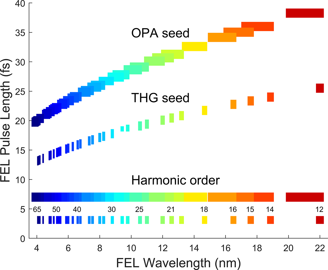
In FEL2 operation, the generated harmonic order mn is always above 12, so the seeding range required to have full tunability is reduced. On the other hand, the double-cascade HGHG requires more power from the seed. A seed peak power of above 200 MW was found to be beneficial for optimizing the FEL performance at the very high harmonics (up to 65) that are currently in use. Figure 6 presents the FEL tunability and pulse duration when the OPA wavelength is tuned in the range of 238–267 nm, the seed pulse duration is 100 fs and the first and second stage harmonic orders span from 3 to 16 and from 3 to 7, respectively. The covered FEL wavelength ranges and expected pulse duration when seeding with a THG pulse with wavelength from 261 to 267 nm and a pulse duration of 60 fs are also presented in the figure. The latter option is currently based on the use of a remote controlled tuneable Lyot-type filter and a common-path harmonic generation setup, offering seed pulse peak power up to about 1 GW.
FEL2 pulse duration with OPA and THG seed, with first stage harmonic orders 3–15 and second stage harmonic orders 2–7.
As mentioned, a key requirement of the seed pulses is the stability of the central wavelength, which is one of the main factors securing the stability of the FEL wavelength. The relatively narrow starting bandwidth and long chain of phase-matched second-order nonlinear interactions in the OPA scheme chosen at FERMI allow one to reliably meet this request. Using a high-resolution spectrometer, it has been verified that both the shot-to-shot stability and the long-term central wavelength stability of the DUV OPA output are extremely good. The relative central wavelength stability δλ c/λ c, where δλ c is the standard deviation, is about a few times 10–5. As an example, Figure 7 shows a 4-h long record of the OPA1 output at a central wavelength of 239.4 nm, measured by the spectrometer at each shot (Gaussian fit). It is worth noting that OPA wavelength settings are based on a preloaded calibration curve so the exact output wavelength may be slightly different. For this reason, the FEL wavelength setting procedure includes readings of the real OPA wavelength and the number of iterations to obtain the needed value; this typically takes a few minutes. When the seed wavelength change is large, for example, 10 nm or more, an optimization of some of the seed parameters (e.g., beam pointing and time delay) may be necessary to obtain optimum FEL performance.
OPA1 output central wavelength stability measured over 4 hours.

For delivering nearly transform-limited pulses, UV pulse compressors had to be adopted on both seed wavelength ranges. UV-fused silica and CaF2-based prism compressors have been tested; however, the obtained performance was not sufficiently good (one reason being the onset of nonlinearity due to the additional material and the related increase of the B-integral value). Therefore, a single-pass double-grating compressor has been used on the seed setup to add the required negative dispersion. It employs custom designed high-efficiency, high-groove density gratings. The gratings for the SH-SFS range have a period of 260 nm (produced by Ibsen and Jenoptik), and those for the FHS range have a period of 300 nm (Jenoptik). One problem (encountered also with the UV stretcher of the photoinjector laser pulses based on the same type of gratings) was grating degradation due to colour centre formation induced by the large accumulated UV dose. This leads to increased losses and beam degradation and requires changing the beam position on the gratings every 2–3 months and replacing them every year. Clearly, this may be a serious issue for applying the same approach in high repetition rate facilities. We have recently tested a new grating pair fabricated by Jenoptik using higher UV resistance material and obtained very promising results indicating that the lifetime of these gratings may be expected to increase by about an order of magnitude.
2.4. UV beam transport and feedbacks
Due to the existing building limitations at FERMI, the closest location where the seed laser could be placed was a room above the undulator hall. The distance between the laser table and the seed entrance window is about 15 m and a number of beam direction changes are needed. The UV beam transport on each FEL line includes 12 mirror reflections. After entering the FEL chamber, the laser pulse travels an additional 9 m to reach the 3 m-long modulator. There are removable multi-screens in front of and behind the modulator, containing also yttrium aluminium garnet (YAG) screens for adjusting the superposition of the laser beam and the electron bunch. However, the FEL layout did not allow extracting the seed beam after the interaction and observing it in real time. Therefore, a virtual undulator scheme has been implemented on each FEL line insertion breadboard. Figure 8 illustrates the setup for FEL1. A fraction of the seed beam is extracted behind a 98% reflectivity mirror and is sent to a multipass arrangement to accumulate the same distance that the seed beam travels inside the modulator. Two positions, separated by about 3 m along this path, are sampled and imaged on charge-coupled device (CCD) VU1 and CCD VU2 to monitor the beam propagation. The optical axis direction is stabilized by acting on piezo-based tip-tilt actuators, one at the exit of the seed laser table and the second one on the laser insertion breadboard, as shown in Figure 8.
Schematic layout of the seed beam insertion breadboard (IBB) of FEL1. SLR, beam from seed laser room; CCD BT, CCD VU1, CCD VU2, cameras for monitoring the beam after the optical transport and in two virtual planes corresponding to the undulator entrance and exit, respectively; EM, energy meter.
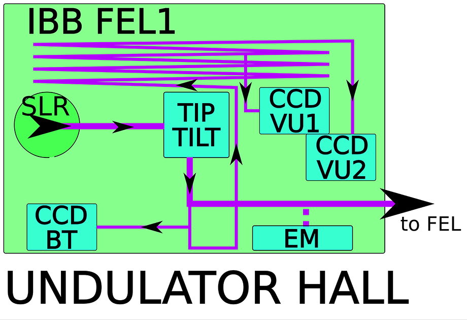
Due to the large distance from the beam source to the delivery point, about 25 m, securing good stability has been a demanding part of the mechanical design. The main optical table and the insertion breadboards are covered by panels and isolated by an acoustic foam, while the rest of the beam path is in low vacuum. As a result, the shot-to-shot pointing stability is sufficiently good, that is, of the order of 20–30 μm RMS. Due to the complexity of the laser system and beam transport, the stabilization of the drifts of the seed beam pointing demanded special attention. The feedback system implemented for this task contains a chain of sub-systems, namely a stabilization of the oscillator pointing, a stabilization of the OPA pump beam pointing and a stabilization of the trajectory and pointing of the UV beam at several locations. In all cases, CCDs are used as beam position sensors and piezo tip-tilt actuators for the pointing control. The compensation bandwidth of the pointing feedbacks is limited to several Hz by the repetition rate of the FEL and by the CCDs; this is still sufficient to guarantee good stability of the FEL. Typical seed beam pointing stability data taken for 8 h (one acquisition per second) by CCD VU2 are shown in Figure 9. The standard deviation of the beam centre of mass is about 20 μm for both axes. We note that on a long time scale the beam reference positions on the virtual undulator screens may become incorrect due to the temperature changes of the environment. For this reason, automatic procedures for periodic pointing optimization of the overlap of the seed beam and the electron bunch and determination of the new reference points have been implemented by the FERMI control group[ Reference Gaio, Bruchon, Lonza and Saule 13 , Reference Bruchon, Fenu, Gaio, Lonza, O’Shea, Pellegrino and Salvato 14 ].
Pointing stability of the FEL1 seed beam position in the horizontal (upper trace) and vertical (lower trace) planes, measured on CCD VU2 over 8 hours of continuous operation at 50 Hz with transverse feedback ON; one shot is registered every second.

The shot-to-shot energy stability of the OPA pulses is typically between 1% and 2% RMS. The long-term stability is maintained by feedback based on a rotating half-wave plate inserted between two of the OPA up-conversion processes.
The optimization of the FEL parameters is done during the machine preparation for every beamtime and may require a few re-adjustments in the course of the beamtime. The most often used seed laser knobs during this are seed beam pointing, seed pulse time delay and energy. In cases where a very clean FEL spectrum is needed, also the UV pulse compression may need to be optimized.
2.5. Timing synchronization and drift stabilization
Clearly, a very important condition for having an efficient and stable seeding process is the tight synchronization of the seed pulses to the electron bunch. Special attention has therefore been dedicated to this aspect at FERMI and a timing system that distributes a precise phase reference along the machine to several sub-systems has been deployed[ Reference Ferianis, Bucconi, Gaio, Mian, Predonzani and Rossi 15 ].
A simplified scheme, containing the main sub-units for the synchronization of the mode-locked 79 MHz repetition rate Ti:sapphire oscillator (Vitara-HP, Coherent), is presented in Figure 10. The course synchronization to the 157 MHz reference signal is performed by the timing unit (TMU) Rf, while the fine synchronization between the pulse train of the Vitara and the reference optical pulse train is obtained and kept stable by the balanced optical cross-correlator (BOCC)[ Reference Kim, Chen, Cox and Kärtner 16 ], both of which are developed in-house. The Rf-phase detection is done at the 38th harmonic of the oscillator frequency[ Reference Sigalotti, Cinquegrana, Demidovich, Ivanov, Nikolov, Kurdi and Danailov 17 ], chosen to coincide with the frequency of the FERMI S band linear particle accelerator (Linac) (2.998 GHz). The main function of the Rf-phase detector is course alignment; therefore, a simple and robust scheme was chosen. It contains two 10 GHz photodiodes converting the optical pulse trains to an electrical signal, and then a narrow band-pass filter selects a single harmonic out of the frequency comb. A vector modulator on the reference path allows one to continuously tune the phase of the reference, and a heavily saturated Rf mixer detects the phase difference. A baseband signal with a ±10 ps dynamic range around the working point is generated and feeds the digitally controlled analogue proportional integral (PI) regulator. Once the laser is Rf locked, the control software acts on the vector modulator to properly align the phase of the fundamental to a common 79 MHz baseline distributed along FERMI. Again with the vector modulator, the software performs a fine scan of the delay, monitoring the output of the BOCC, until a temporal overlap between the two pulse trains in the BOCC nonlinear crystals is achieved and a sum frequency signal around 527 nm is obtained. A typical BOCC signal scan is shown as an insert in Figure 10. The temporal width of the linear zone is about 300 fs, and the slope is in the 7–10 mV/fs range, allowing the required high sensitivity.
Schematic layout of the seed laser synchronization setup. TMU Rf, coarse synchronization unit; LNA, low-noise amplifiers; PI, proportional integral; TMU, timing control unit; Ti:Sa, titanium sapphire; pzt, piezo-based actuator.

The present version of the oscillator has two intracavity actuators (a motor and a fast piezo actuator). The sealed cavity and proper mechanical and optical design allow a low intrinsic phase noise of the oscillator. When locked optically, its residual timing jitter is as low as 1.5 fs RMS (measured out of loop, bandwidth 10 Hz–1 MHz, see Figure 11(a)). Importantly, the oscillator synchronization exhibits a limited timing drift. An out-of-loop measurement using a second BOCC was performed in order to correctly measure it. A typical measurement showing less than 5 fs over 68 h is presented in Figure 11(b).
(a) Phase noise and timing jitter of the seed oscillator. Left axis, integrated timing jitter; right axis, phase noise spectral density. (b) Timing stability of the seed laser oscillator, measured out of loop using a second balanced optical cross correlator (BOCC).

Each of the regenerative amplifiers of the system is triggered with a separately adjustable delay to select and amplify to a 5 mJ level a 50 Hz train of pulses from the oscillator. The 6.5 ns delay line shown in Figure 10 allows one to continuously vary the delay of the output pulse of both amplifiers. A second delay line is placed in front of RegenAmp1 to provide an independent timing change. In this way, any needed time difference between the seed and SLU pulse can be obtained.
The amplification process in the Ti:sapphire regenerative amplifiers typically requires at least 10 cavity roundtrips, so it can introduce timing jitter and drifts. The shot-to-shot timing jitter of the amplifier output pulses with respect to the oscillator train was measured to be of the order of 5–6 fs RMS for the first amplifier and below 2 fs RMS for the second one where the mechanical design has been improved. A more detrimental effect for the functioning of the system may come from the slow timing drifts: even in a very stable temperature environment the timing of the amplifier output pulse may easily reach hundreds of fs and lead to a deterioration of the seeding process, as well as to an error in pump–probe experiments based on FEL and SLU pulses. For this reason, a stabilizer for the amplifier timing was designed and implemented from the very beginning. It is based on single-shot cross-correlation, where fractions of the compressed amplified pulses and oscillator pulses are crossed at an angle and frequency mixed in thin beta barium borate (BBO) crystals and the generated signal imaged on a CCD. In this geometry, the time arrival difference of the two pulses is mapped into the horizontal position of the image and can be easily stabilized. The resolution of both cross-correlators is below 2 fs. A campaign of measurements during the setting-up of the system indicated that the timing jitter and drifts of the DUV pulses generated by the OPAs with respect to the pump pulses were negligible.
2.6. Pump–probe laser pulses from the seed laser system
In a seeded FEL, the timing of the generated pulse is firmly determined by the seed pulse. The unavoidable fluctuations of the electron bunch arrival time in the interaction zone with the seed pulse therefore do not cause FEL pulse timing fluctuations. To take a full advantage of this property, at FERMI an IR pulse generated by the seed laser system, referred to as SLU, is optically transported to the end-stations and utilized for pump–probe measurements. Details of the main challenges and applied solutions can be found in Refs. [Reference Allaria, Castronovo, Cinquegrana, Craievich, Dal Forno, Danailov, D’Auria, Demidovich, De Ninno, Di Mitri, Diviacco, Fawley, Ferianis, Ferrari, Froehlich, Gaio, Gauthier, Giannessi, Ivanov, Mahieu, Mahne, Nikolov, Parmigiani, Penco, Raimondi, Scafuri, Serpico, Sigalotti, Spampinati, Spezzani, Svandrlik, Svetina, Trovo, Veronese, Zangrando and Zangrando3,Reference Cinquegrana, Cleva, Demidovich, Gaio, Ivanov, Kurdi, Nikolov, Sigalotti and Danailov4]. The most important points and features are as follows. The IR beam from the source amplifier (RegenAmp1 or 2) is partially uncompressed to about 10 ps and sent through approximately 130 m long low-vacuum beam transport to a common distribution point (CDP in Figure 12) located in the FERMI Experimental Hall. There the beam position is monitored and stabilized, the pulse is compressed and, after a variable delay line, is directed to one of the five FERMI beamlines through other sections of low-vacuum transport. The beamline optical breadboards have different sizes and layouts adapted to the space and needs. In general, they all contain frequency conversion stages (up to the fourth harmonic), polarization and energy control, as well as beam/pulse diagnostics and stabilization of the position of a virtual sample. As an example, a detailed description of the SLU-based pump–probe setup of the FERMI LDM station can be found in Ref. [Reference Finetti, Demidovich, Plekan, Fraia, Cucini, Callegari, Cinquegrana, Sigalotti, Ivanov, Danailov, Fava, Ninno, Coreno, Grazioli, Feifel, Squibb, Mazza, Meyer and Prince18]. For giving access to wavelengths not covered by the harmonics, a noncollinear optical parametric amplifier (NOPA) or OPA can be inserted at present in some of the beamlines. A dedicated 795 nm pumped OPA with tuneable harmonic conversion options with a wavelength range spanning from 240 nm to 15 μm will be available by the end of 2021. A gas-filled hollow-core fibre spectral broadening and compression setup delivering sub-20 fs pulses at the fundamental wavelength will also be installed in the coming months. The main SLU pulse parameters are listed in Table 2.
Schematic layout of the seed laser for users (SLU) system. SLR, beam from the seed laser room; Low Vacuum BT, optical beam transport in chambers and tubes at 1–10 mbar vacuum level; CDP, common distribution point of the SLU pulse in the FERMI Experimental Hall; CCD BT, camera for beam position control; COMPR, grating compressor.

Main parameters of the seed laser for users (SLU) pulses at the FERMI end-stations.

3. Outlook: seed laser system upgrade for EEHG seeding
There is a strong interest in extending the wavelength range of externally seeded FELs to shorter wavelengths. A promising root in this direction is the use of the so-called EEHG scheme[ Reference Stupakov 19 ]. One of the important advantages of EEHG with respect to the HGHG scheme is its low sensitivity to the unavoidable electron beam deterioration (e.g., spurious electron energy modulation) during acceleration and compression. This makes EEHG particularly suitable for the generation of high-quality radiation at harmonic numbers much higher compared to HGHG. After the successful EEHG test experiments conducted in 2018[ Reference Stupakov 19 ], it has been decided to proceed with an upgrade of the FERMI FEL1 with the aim to extend its wavelength range down to 10 nm by adding an EEHG seeding option. It is planned to commission and deliver this option to users in 2023. This requires the generation, propagation and insertion of a second tuneable DUV seed pulse (referred to further in the text as Seed 2) in a second (new) modulator. It is envisioned that within a few years after that, also FEL2 would be upgraded to a hybrid mode to reach 2 nm, by operating the first cascade in EEHG mode. Below we present the seed layout designed to support both modalities.
For what concerns FEL1 in EEHG mode, an analysis of different possible options for Seed 1 and Seed 2 pulses was made, taking into account the limitations imposed by the existing modulators, as well as the results from the FEL process simulations and the experience accumulated during the EEHG campaign on FEL2[ Reference Ribič, Abrami, Badano, Bossi, Braun, Bruchon, Capotondi, Castronovo, Cautero, Cinquegrana, Coreno, Couprie, Cudin, Danailov, De Ninno, Demidovich, Di Mitri, Diviacco, Fawley, Feng, Ferianis, Ferrari, Foglia, Frassetto, Gaio, Garzella, Ghaith, Giacuzzo, Giannessi, Grattoni, Grulja, Hemsing, Iazzourene, Kurdi, Lonza, Mahne, Malvestuto, Manfredda, Masciovecchio, Miotti, Mirian, Petrov Nikolov, Penco, Penn, Poletto, Pop, Prat, Principi, Raimondi, Reiche, Roussel, Sauro, Scafuri, Sigalotti, Spampinati, Spezzani, Sturari, Svandrlik, Tanikawa, Trovó, Veronese, Vivoda, Xiang, Zaccaria, Zangrando, Zangrando and Allaria 20 ]. As a result, the seed pulse parameter set listed in Table 3 has been decided. We note that having Seed 1 around 390 nm (i.e., based on direct second harmonic of the regenerative amplifier output pulses) would have been beneficial in terms of higher pulse quality and simplicity in the generation of the required peak power. Also, seeding at 390 nm would have offered an increased tunability by using different harmonic orders n (EEHG resonance is defined by the two indexes m, n, see the definition in Ref. [Reference Stupakov19]). However, such a choice would not be compatible with the planned FERMI Linac energy upgrade to 1.8 GeV and the existing modulator parameters (resonance wavelength below 300 nm for such bunch energy), and for this reason a third harmonic-generated 260 nm range pulse will be used as Seed 1.
Main parameters requested for Seeds 1 and 2 in EEHG mode.

Figure 13 shows that a full FEL tunability is guaranteed in the 10–20 nm range in EEHG mode by the use of a fixed Seed 1 wavelength of λ 1 = 264 nm, a harmonic order n = –1 and by tuning the wavelength of Seed 2 in the λ 2 = 245–266 nm range with switching the harmonic order m in the range m = 13–26. The assumption is that a full FEL tunability above 20 nm will be provided, when needed, by switching to HGHG mode and using the standard seed ranges. In this way, the requested Seed 2 pulse tunability in EEHG mode is restricted to the range of 245–266 nm, allowing one to guarantee optimum pulse parameters despite the larger distance and the more complicated layout necessary for the Seed 2 pulse beam transport. Thus, the approach used in HGHG seeding, namely generating the tuneable DUV pulses on the seed laser table (at present the last up-conversion process takes place inside the OPA box) and then transporting them to the seed insertion breadboard in the vicinity of the undulator, can be modified as follows. Only the first stage of the OPA signal pulse up-conversion, that is, the frequency mixing with the pump generating 490–532 nm light, will remain inside the OPA. The visible range output pulses would then be transported optically to the insertion breadboard by a set of optimized low loss dielectric mirrors (i.e., >99.8% reflectivity per surface in the full range) with negligible added group delay dispersion. The dispersion pre-compensation for the beam transport material in transmission (windows and samplers) in this range is much easier than in the DUV as well. The last up-conversion stage, that is, generating the DUV light in the range of 245–266 nm, will be done very close to the insertion point by a tuneable second harmonic (SH) unit; the total loss introduced by the few remaining DUV mirrors and the intra-vacuum mirror is then expected to be at the 10% level.
Expected tunability of FEL1 in echo enabled harmonic generation (EEHG) mode by using harmonic order n = −1 and harmonic order m = 13–26.

The proposed new laser system layout is presented in Figure 14. One essential point taken into account was that for supporting the pump–probe experiments at the end-stations, in addition to Seed 1 and Seed 2 pulses, also the SLU pulses need to be delivered with different and independent timing. This can only be obtained by the introduction of a third regenerative amplifier (RGA3 in Figure 14). Depending on the mode of operation, the latter will be used as a source for one of the seeding pulses or of the SLU pulse. In HGHG mode, the seed pulse will be provided by RGA1 for FEL1 and RGA2 for FEL2 operation.
Planned seed laser system layout after the upgrade. RG1, RG2, RG3, regenerative amplifiers; IBB1 FEL1 and IBB2 FEL2 are the insertion breadboards of the corresponding seed pulse to the FEL lines; SH, second harmonic; EOS FEL2, beam provided for electro-optical sampling setup; the solid blocks and arrows indicate existing units and beam transport lines while the dashed blocks and lines indicate planned additions.

In the latter case, it is planned to enlarge the range of third harmonic generation (THG) tunability and use it more often. In addition, it is planned to test the compact and efficient fourth-harmonic generation (FHG) setup developed for delivering pulses to the end-stations also for seeding FEL2 at 200 nm. While of limited tunability, such seeding may prove very useful for increasing the FEL energy in the 4 nm range. For the source of the SLU pulses, the present scheme can be used (i.e., RGA3 remaining idle in this case), or RGA3 could deliver the SLU pulses. We note that in this configuration, when FEL2 is operated, a portion of the RGA2 pulse will be used to pump the electro-optical sampling (EOS) setup, which has recently been successfully tested.
4. Conclusions
The first version of the FERMI seed laser system was designed about 13 years ago and has been used for HGHG seeding for more than a decade, successfully satisfying the main requirements and offering very high reliability (exceeding 99.5% uptime during user runs in recent years). While the complexity of the laser system and of the optical setups has strongly increased, the underlying technology remained unchanged. At the same time, ultrafast laser technology has undergone an impressive development worldwide, whereby modern systems are more compact, efficient and robust. A strong competitor of the Ti:sapphire nowadays is the Yb-doped gain-medium based laser technology, which is intrinsically more efficient and gives access to ultrashort pulses at average power levels unthinkable in the past. For this reason, FEL facilities employing superconducting technology and burst mode operation rely mostly or entirely on Yb-based technology. Yb-laser pumped NOPA and optical parametric chirped pulse amplifier (OPCPA) developed at other facilities[ Reference Pergament, Palmer, Kellert, Kruse, Wang, Wissmann, Wegner, Emons, Kane, Priebe, Venkatesan, Jezynski, Pallas and Lederer 21 – Reference Mecseki, Windeler, Miahnahri, Robinson, Fraser, Fry and Tavella 23 ] have shown impressive performances, and are a solid base for success in the ongoing projects for seeding FELs at very high average power in burst and even continuous wave modes. On the other hand, in low repetition rate FEL facilities Ti:sapphire and Yb-based pump laser technologies may co-exist, with the former remaining competitive for seeding applications in the next few years.


 Open access

